
|
|
THE PROCESS THAT ALL BEGINNERS FEAR: FINISHING AND FITTING THE PISTON AND CYLINDER by Ken Croft Summary The purpose of this essay is to clarify what an engine builder is attempting to achieve when finishing cylinders and pistons in model internal combustion engines, and to describe a method of finishing pistons and cylinders that can be understood and applied by those who live in fear of this final make-or-break operation in engine construction. It is based on 30 years of personal experience in engine building and many years of association with the Internet group "Motor Boys International" of which I was a member until the group's effective disbanding following the untimely death of Ron Chernich in early 2014. I will not be dealing with ringed pistons, which may form a later topic. I am only dealing with iron or steel components. Fitting and finishing of ABC, AAC, etc., arrangements are considered as specialist and are not discussed here. This will be a blow by blow account. It does not offer choices, it gives instruction. I fear that some grannies will be told how to suck eggs! I make no apologies. My intent here is smply to document a method that works. Who am I? Ken Croft, a retired graduate engineer from England. Married with children. Lifelong aeromodeller. Every engine of the 40 different designs that I have built has been constructed with the intention of powering a model aircraft. Most are replicas of vintage model aircraft engines, some of them extremely rare. I do not make display models to sit on a shelf. Almost all are what I call "simple singles" in that with a few exceptions they are single cylinder 2 cycle designs. A photo gallery of the engines that I have built may be found here. I have a tiny workshop housing a Myford Super 7b lathe, a cheap Taiwanese mill/drill, a small bench drill, and one luxury item with which we will not concern ourselves in this article, a bench model Delapena [Sunnen] honing machine. If necessary, I pour my own castings, including pattern making and permould die making, the latter being avoided whenever possible. Additional interests are digital photography, mending other people’s computers, playing my squeezebox, and holidaying in my camper. OK, now you know me!! So let's get on with it. What are we trying to achieve? Contrary to what a newcomer might expect, we are not trying to achieve a cylinder with a parallel bore. On the contrary, tapered is good. And we are definitely not lapping the piston in the cylinder. Let me explain this last point first. In a finished and working engine, the clearance between the piston and the cylinder is so small that if it were possible to have lapping paste between the piston and cylinder, as would be the case if the piston was being lapped inside the cylinder, then the gap between piston and cylinder would already be too large for the engine to run. Moreover, you would have no control over the surface finish or the tapers. So do not do it. Never consider pushing the piston up and down inside the cylinder with anything like lapping paste anywhere near to it. Having disposed of that issue, let's consider why we want a tapered cylinder bore. One reason is that at the bottom of the stroke, the exhaust ports are open and there is no good reason for a tight piston top seal since all the gasses above the piston are rushing out of the ports. We do however need an adequate seal to create the compression in the crankcase that transfers the new charge up through the bypass ports and into the cylinder. But crankcase compression is very low in comparison with cylinder pressure that is created when the charge fires, and so we don't need as tight a seal at the cylinder bottom end. At the top of the cylinder however, temperatures are high and the cylinder expands more than the piston, because the piston is cooled by the incoming fresh charge. This difference in expansion makes for increased clearance between the piston and cylinder at the top end, resulting in loss of compression, loss of power, and bad hot-starting. The solution is to make the piston fit at the top of the cylinder a little too tight when cold, so that the hot running fit is just right. It is mostly guesswork at our "hobby" level of engine building, but experience tells us what is needed. You will by now realise that what we need is a cylinder which has a slightly bigger bore at the bottom, making a relatively slack fit down there, and a somewhat smaller bore at the top, giving a relatively tight piston fit at top dead centre. These are the technical reasons why tapered is good. But there is a real practical reason too. Imagine that you have a beautifully finished cylinder sitting gleaming on the bench, with an absolutely parallel bore. You are separately lapping the piston, cleaning it down, oiling it, and trying it in the bore. Of course it will not go in. You lap some more, clean and oil some more, and it still does not go in. Then suddenly, at your last attempt, it shoots right in and out of the other end! What are the chances of the fit being correct? Not very high! Now imagine the same scenario but with a tapered bore. The piston goes in a little way. Then next time a bit further, then a bit further, and as the job progresses, the piston goes as far up the cylinder as experience [and this article in a later section] tells you it should, and the fit is exactly what you want it to be. So there you have it; tapered is good. Pistons are another matter. Racing engine pistons are often parallel with slightly relieved bands in the centre, or relief at the top. For our purposes, we try to achieve a parallel piston. Diesel contra pistons are another matter. I suggest you follow the DCO method developed by the late David Owen and detailed by Ron Chernich in his Weaver construction feature which is still to be found in his fine "Model Engine News" (MEN) journal. There is no better method. Now a few words about surface finish. Just how shiny do we want the parts to be? Commercial engines using steel or cast iron pistons and cylinders often have criss-cross surface marks showing on the piston and cylinder. These are the result of the grinding or honing operations used in production engineering. It is often said that these minute grooves are an aid to lubrication as they retain oil. Indeed, a friend of mine who is a highly respected model engine builder, and an ex-toolmaker from no less than the Rolls Royce aero engine factory, can quote a problem with engine valve guides that was only solved by reducing the glass-like finish on the bores to one with typical criss-cross honing marks. That said, my personal view is that in our little engines any oil retained by the grooves will rapidly suffer heat degradation and will not act as a lubricant, in fact quite the opposite. The Russian makers of the finest and most powerful racing engines in the international class always polish their cylinders to a glass like finish. The Russian and Swedish 1.5 cc engines used in tether cars are finished like that, and they turn a massive 44,000 rpm. That's good enough for me. Go for glass and get the best finish you can! Working method Here are the steps that we have to follow, in order:
Begin the process by completely machining the cylinder, forming the bore using a boring tool to the best possible finish that you are able to achieve. I personally use Sumitomo tooling which uses indexable tips which I believe are of Titanium Carbide. It is expensive and difficult to obtain in the small sizes that we engine builders need, so a freshly sharpened boring tool of conventional tool steel will be good enough. I avoid reaming unless the bore is so small that I cannot get a boring tool down. With reaming I cannot guarantee that the reamed hole is concentric with anything, and I sometimes have a problem with reamers producing a fluted hole. When boring a cylinder, always put the tool down the bore several times at the same setting, as with very fine cuts the tool will tend to push-off the work. Three of four passes down the bore are usually good enough. Then you will lap the cylinder, clean it thoroughly with gasoline or cellulose thinners, then oil it with sewing machine oil. Then measure the bore at the bottom as accurately as you can. Put it somewhere safe. Now you make the piston. Machine it all over, getting the best tooled finish you can on the outside diameter, and make the diameter exactly the same diameter as the bore of the cylinder at the bottom. If you cannot work to within half a thou, then make the piston about a thou oversize. This done, we lap the piston. Lapping details will follow - be patient! Process requirements What tools de we need for the lapping operation? What do we need to buy and what do we need to make? In simplistic terms, you need to buy lapping paste and you need to make a lapping tool for the cylinder and also for the piston. You also have to make a dummy rod end to hold the piston whilst lapping. Lapping paste
I should tell you that in the days when I used automotive lapping pastes and various concoctions borrowed from my place of work, I slapped the stuff all over the place. It was the messiest operation in the whole business of engine building. I knew that diamond compounds seemed extremely expensive and big bucks bought very small amounts. I was scared-off by the expense, but I was all wrong. Diamond compound does cost more than carborundum-based grinding paste, and you do get only a stingy little syringe with a few cc's of the compound. But it works very differently from the other stuff. You need very little for it to work well, and it works quickly. Because it potentially works quickly, I use a very fine grade to slow down the lapping action, with the benefit that I use just the one grade to go from a normal fine machined finish to a mirror-like shine you can see your face in. So go ahead and place your order, or do a Google on the internet to find a supplier in your area Laps As you will be using diamond compound [you will, won't you?], you should ideally make your laps from brass, as my jeweller friends tell me that diamond has a great affinity for copper. I personally use aluminium alloy as I have plenty and I never have brass, but I bow to greater experience. My frustration with aluminium as a lap material is that it laps away faster much than the job I am lapping, and that is a bit frustrating. So you have a choice, brass to be good or alloy for convenience. The cylinder lap
That is the lap made. Have a up of coffee, sit back and relax and admire your work. I always do!
The piston Lap This is easy. In essence it is a bush which fits around the piston, which can be adjusted in diameter to exert more or less pressure on the piston when in use. It is perhaps best described by looking at the pictures below.
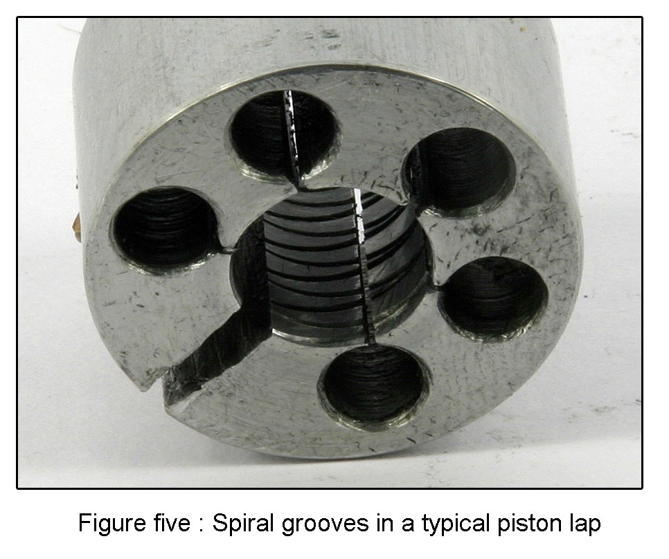
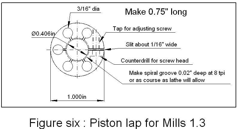
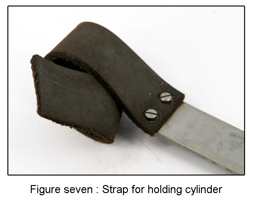
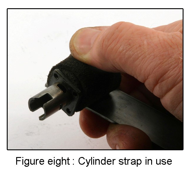
Make the lap no longer than the length of the piston, and make the bore of the lap so that it just fits over the piston. When you split it, it will probably fool you by closing up a little, but that does not matter. After boring the central hole about a thou larger than the piston diameter, set the lathe to cut a screw thread in the bore of about 8 tpi and run a screw cutting tool down the bore a few times to make a groove about 20 thou deep, not a full depth thread!. In fact I do two spiral cuts, a left and a right hand cut. The purpose of these grooves is simply both to retain lapping compound and to allow the oily products of the lapping to wash away. Any clamp screw will do but I prefer the socket headed variety. Let's make a start! Set the lathe to run at around 100 rpm or so and mount the cylinder lap in the 3 jaw chuck. Smear about a 1/2" length of diamond lapping compound onto the outside of the lap, and with the lathe not turning, use the flat of a 6" steel rule, or a piece of tool steel held against the lap, to embed the fine diamond grit into the lap. Now put the cylinder, bottom end first, over the lap and tighten the grub screw to expand the lap until when you turn it by hand, it feels like it is starting to grip the cylinder. Before running the lap in the lathe, you need to make some arrangement for holding the cylinder that will not distort the cylinder and will not cause injury if the lap grabs on the cylinder and rotates it. Some use a simple wood and leather strap; others use a wooden tongs arrangement. Others simply hold the cylinder in a gloved hand, but I do not recommend that. As an industrial engineer I know that there have been horrific accidents in which a gloved hand has been peeled of its flesh when the glove has been grabbed and rotated by a machine tool, so please do not be tempted. I use a leather strap as shown in the pictures below.
When the cylinder is in place on the lap, squirt some white spirit, turpentine or paraffin over the lap and cylinder. Holding the cylinder by your chosen means, run the lathe. Push the cylinder forward and back along the lap at about half rotational speed. If the lap is turning at 2 revs per second, stroke the cylinder forward and back at one stroke per second. You should aim for about 1/2 the lap length to stick out of the cylinder at each end of the stroke, and if you have made the lap as described, the forward stroke will be limited to exactly this extent. The turpentine [or whatever] acts as a lubricant and a medium to clear the lapping debris. If you use thin oil instead of turpentine, the diamond will cut more slowly. Almost immediately, black gunge will ooze from the job and the lap will go slack. Stop the lathe and adjust the lap until it drags, then start again. After a couple of minutes, more or less, clean the cylinder and see what is happening in there. At first you may see nothing much, but eventually the machine marks will start to disappear. Carry on lapping and squirting lubricant, and if the change is really taking too long, try a bit more lapping compound. Just ease it into the saw cuts in the lap. Eventually when the machine marks in the bore are well on their way to disappearing, we start the tricky part, where either experience or good measuring equipment are needed. You need to produce the taper in the bore. This is done quite simply by lapping the bottom end of the cylinder more than the top end. In other words when stroking the lap, allow the lap at every stroke end, to protrude out of the bottom of the cylinder, ensuring that the bottom is always in contact with the lap, but allow the lap to only barely poke out of the top end of the cylinder. The top will only be getting lapped when in contact with the lap, which is part-time, but the bottom will always be getting lapped. Proceeding in this manner until all machining marks are gone will produce a tapered bore with a mirror-like finish - trust me! For a first engine, that will do. Completely clean the cylinder by lots of scrubbing with gasoline, or cellulose thinner [my favourite] and an old tooth brush. Take care to clean out the ports, and use a pipe cleaner to poke about if necessary. Do not believe the old books on engine cleaning that advise lots of hot soapy water. Do that and you will still have lapping compound lurking waiting to grab you unawares. After cleaning, oil with light sewing machine oil, and measure the bottom of the bore as accurately as you can. This dimension will be used both for sizing both the piston and the piston lap. If you want to be absolutely sure that your cylinder is good, you might want to investigate obtaining a bore comparator. They are very expensive, yet can be bought on eBay for about 1/10th of the new price. I bought mine for about £30, my set covering the typical range of bores in our small engines. The type I use has a measuring head in the form of a plunger that goes down the bore, and at the other end of the instrument is a dial gauge. As the bore changes, the plunger movement is converted to a pointer movement which can be as accurate as 40 divisions on the scale for 0.001" diameter change. With such an instrument you can carefully move it down the bore and watch the pointer move as the head moves along the tapered bore. For actual measurement you can set a marker at the pointer location, then with the comparator withdrawn from the job, use an accurate digital micrometer to return the pointer to the mark, and read the diameter from the mike. I have to say that although it all sounds a bit clever, I would be lost without mine. On the cheaper and more obtainable side, you can buy telescopic gauges which you push down the bore, lock them with a twist of the handle, then measure over the telescopic plunger when the instrument is withdrawn from the bore. These are not easy to use but are inexpensive. I have a set of these by Mitutoyo which when you lock them, they slacken off to a smaller diameter, so you need to softly lock them at an angle, then rock them, if you understand. By contrast I have a single such gauge made by Moore and Wright, that locks perfectly and is a delight to use. On a little engine like a Mills 1.3, I would look for perhaps a thou difference between the bottom of the cylinder and the exhaust port area, then a couple of tenths at the most between the diameter at the exhaust ports and at top dead centre. Onwards towards the piston Now you know the diameter of the bottom of the cylinder, you can machine the piston. Make the final machined diameter as good a finish as you can get it, and the same diameter as the cylinder bottom bore. The piston should at this stage just feel as though it would just possibly start to enter the cylinder if you have it a hard push. If it does enter, you probably do not have enough material on the piston to lap out the machine marks. If it will not enter at all, then you may have too much material to remove by lapping. If you get it wrong, be patient, and just make another one. Having made the piston I like to just take the edges off the piston pin holes using an ordinary drill point. I feel it just gives less of a sharp edge there to crumble away during lapping, or when the engine is running. Hard to explain, but it just feels like the right thing to do.
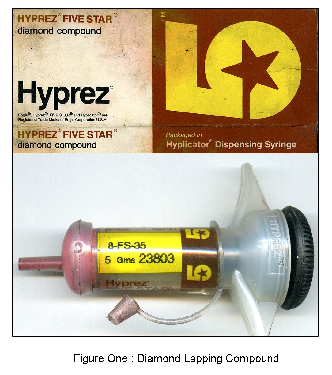
Mount the dummy rod (with its piston mounted) in the 3 jaw chuck with the lathe set to run at about 100 rpm. Rub a small amount of diamond compound into the bore of the lap using a steel rod. Hold the lap in your hand and put it over the piston. Lubricate with the same stuff as for the cylinder, and run the lathe. Once again stroke the lap at half the rate of the rotation of the piston. Try to keep the lap in line with rotation - the piston is floppy and you have only your eyes to guide you. [As an aside, I have seen simple laps made without a clamp screw, but adjusted by simply putting a hose clip round the lap to compress it. This works fine until the rotating piston grabs the lap and the consequently rotating lap tears a hunk from your hand. Except when using my fibre piston pin - this just breaks!] Now, stroke the piston for a minute or so, letting the lap uncover the piston by about 1/2 its length at each end. Stop and clean down and examine the finish. If you are sure you have cleaned the piston properly, [and it really is a pain to keep doing it], then try the piston very carefully in the bottom of the cylinder. It should just start to enter. Carry on lapping the piston, and carry on meticulously cleaning the piston and trying it in the bore. As the machine marks steadily disappear, you will be able to get the piston to go further up the bore at each attempt. Now read this next bit very carefully. The chances are that if you get the piston to go all the way up the bore to top dead centre, it will be too slack. You may get away with it, certainly on a spark engine, probably on a glow, but unlikely on a diesel. What you are aiming for is to get the piston roughly half way past the exhaust ports. In other words well up the cylinder, but a bit off the top, before it jams. And don’t worry; it will jam at some point during this sizing process. Panic not; just tap it out from the top end and carry on lapping until it goes just the right amount up the bore. Then clean down thoroughly, and you can assemble the engine. The final showdown When you are sure that the piston and cylinder are scrubbed clean, sparkling and well oiled, you can assemble the engine. I always make lapping the last job on any engine. You will find that with a propeller fitted, the piston should have a nice tight nip at top dead centre. Possibly even an alarming nip, but worry not. The chances are that on the first burst of running, there will be a small discharge of black gunge from the ports and within seconds the nip will have become a lot less. If after a few minutes running the engine is still too tight when hot, it is a simple matter to remove the piston, and a very small amount of lapping in the lathe [you will be surprised how little it takes] will free the nip to a better fit. I must say that when I used to use automotive grinding paste, which produced a good finish but nothing like that produced by the diamond compound, I often got quite a splurge of black gunge from the ports on the first run, and the nip at the top would have completely disappeared. When using diamond compound. I often find that the nip at top dead centre that is present when the engine is first assembled is much more likely to remain unless I ease the piston with further lapping, and there is very little black gunge from the ports on the first run. The proof of the pudding A fellow engine collector living local to me confessed that although he had rebuilt engines and made various parts, he had never successfully re-bored an engine, not ever having achieved a running piston cylinder fit. I was at the time restoring a Mills 2.4 cc diesel so he came round and stood alongside as I took him through the actual lapping process. I suspect that in under an hour, but maybe a bit longer, we went from a lapped cylinder and a machined but un-lapped piston, to an engine that was happily running on the test bench. He went away fired with enthusiasm, and within a week or so phoned to say that he had re-bored an engine which ran successfully, for the first time ever. Acknowledgements I am indebted to Stan Pilgrim of the Motor Boys International for introducing me to diamond lapping compounds. And to the late David Owen, also of MBI, for his contra piston system And to Motor Boys International for their friendship and encouragement in this small world of enthusiasts that we inhabit. Diamond compound details I use "HYPREZ Five Star diamond compound" packaged in a "Hyplicator Dispensing Syringe". Although made in the USA, it is available in England packaged by a company called "Engis". The grade I use is called Grade 8-FS-35, for a 5 gram syringe. Engis will no longer supply direct to individuals, but note that Cromwell Tools in England can supply it. The current cost is £33 per syringe. Use this link to see the actual material which I'm recommending. Residents of other countries may of course be able to source this material more locally. ________________________________ Article © Ken Croft, 2017
.
|
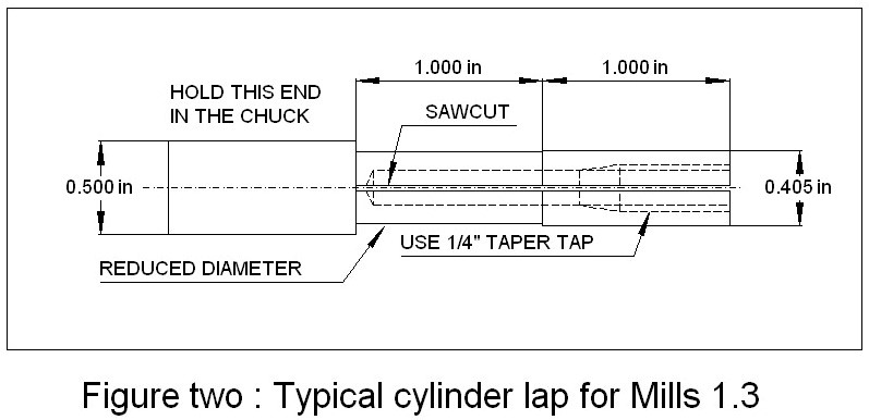 A lot has been written about laps which makes them seem very clever and sometimes complex, but unless you are into a major production run, I recommend the simplest of all. For the cylinder lap, find a piece of alloy [brass in your case] about twice the length of the cylinder. Now turn 2/3 of the length down so that it will just neatly fit into the cylinder, all the way. Then reduce the diameter in the centre region of the bar by a further 20 thou or so to leave a length at the lapping end only 2/3 the length of the cylinder; this is the bit that does the lapping. This length is important. You do not want a lap longer than the cylinder bore, or you will produce a bell-mouthed bore, and a very short lap length can produce all kinds of problems. See the attached drawing for the proportions described.
  Ensure that the plain end that goes into the chuck is larger than the end you have just machined. The reason will be explained later. Now drill a tapping hole for a 1/4" thread the full length of the machined part, and tap the hole for a short distance only, with a TAPER TAP [sometimes called a 1st tap]. The reason for the taper tap is that in use you will put a grub screw into this hole, and as it rides into the taper it will expand the lap, but only after the next operation. Take the part out of the chuck and with a hacksaw, make a saw cut the length of the machined end. File off any rough edges on the saw cut. Put a grub screw into the tapped hole
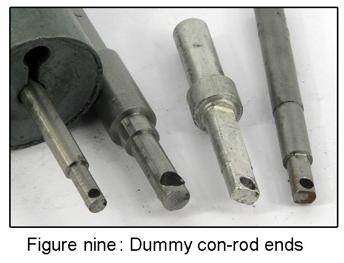 You now need to make a piston lap, as already described, and you need to make a dummy rod end. The way of holding the piston is my own method. Nobody else does it this way, but it works, so please do it my way. Just take a piece of 3/8" diameter steel or alloy, and machine the end so that it will go up inside the piston with a very loose and waggling fit. Now cross-drill the end of this rod for a very oversize piston pin hole. For a 1/8" piston pin, drill a 5/32" hole. Now machine a dummy piston pin from a fibre material, or even wood, and make it a press fit into the piston. When you assemble the piston on the end of this dummy rod end, with its pressed-in fibre piston pin, you will have a piston flopping about all over the place. That is correct. You will have a piston which cannot possibly end up barrel shaped after lapping, because it will not be possible to put any uneven side loads or twisting loads onto the piston with the lap. Also if the lap should grab the piston, the fibre rod will break and no harm will come to either yourself or the piston. So trust me, I'm not a politician!
 | |