
|
|
Kremlin Klassic - the Russian K-16 Diesel Evaluated
According to the knowledgeable contemporary Russian commentator A. V. Filipichev, the K-16 was a very flexible engine which was suitable for use in an unusually wide range of models, including boats and cars as well as aircraft. It was reportedly manufactured in relatively large numbers, remaining in production up to the mid 1950’s. Later commentator Viktor Khodyeyev of Ukraine went further in his very interesting book on model engines produced in the former Soviet Union (USSR). A German-language edition of this book was published in 2014 under the title “Modellmotoren Made in USSR” (ISBN 978-617-534-277-0). Khodyeyev stated that the K-16 was in fact the first model diesel engine to enter series production in Russia, although it was by no means the first model diesel to be developed there. He confirmed that the K-16 was produced in quite large numbers over a fairly long period, hence remaining fairly common even today in geographic areas which were formerly incorporated into the USSR.
Rather confusingly, in his very informative article entitled "Russia's Engines" which appeared in the September 1953 issue of "Model Airplane News" (MAN), Peter Chinn mentioned an engine called the AMM-12 which appears to have been virtually identical to the K-16. Neither Filipichev nor Khodyeyev mentioned this model. It may possibly be the same engine produced at a different factory - Chinn actually acknowledged this possibility in his 1953 article. Examples of the K-16 turn up today under both designations. By either name, this is one of the best-known early Russian diesels. However, it was never exported to countries outside the Soviet bloc, hence remaining relatively rare outside the regions which were included in the former Soviet Union. I do not intend to repeat any of my earlier comments regarding the broader context in which this engine was produced. Readers wishing to know more about the big picture are referred to my original article. Here I’ll confine myself to a summary of this particular engine’s background as well as a description of the engine itself. I’ll follow this up with a bench test report. Background The K-16 diesel seems to have appeared in the latter part of 1949. Certainly, it was setting records by June 1950, implying that it must have made its appearance some time earlier. Khodyeyev tells us that the engines were manufactured at DOSAAF’s No. 6 plant, but frustratingly does not tell us where this was located. Can any reader provide clarification on this matter? This is a frequent criticism of Khodyeyev's otherwise excellent book - although very useful indeed as a general reference, it is annoyingly short on details. For example, no information is provided on serial number ranges - an obviously necessary inclusion in any really useful model engine encyclopedia. Production date ranges are also dealt with very incompletely and imprecisely. Despite these criticisms, Khodyeyev's book remains a highly recommended reference.
Interestingly enough, the recommended fuel mixture for this engine was equal parts of gasoline, kerosene and aircraft engine oil. According to the owner's manual, an ether-based fuel performed significantly better, but ether was apparently very difficult to obtain at the time in the USSR. The manual even stated that a straight kerosene/oil mix could be used at a pinch when ambient temperatures were high, but starting was then said to be very difficult and stresses on the engine were high. The absence of any ignition improver was probably due primarily to its general unobtainabilty at the time, although its absence was quite appropriate given the evident fact that this was not a high-speed engine. The makers claimed an output of up to 0.11 Kw (0.1475 BHP) @ 5,000 rpm, with a maximum operating speed of 6,500 rpm. Clearly this engine’s strong suit was low-speed torque development! In keeping with this impression (which will be tested later), each unit was supplied with a 350 mm (13.8 in.) diameter wood airscrew of unspecified pitch.
At this time, Russian modellers were very much focused on setting records in a wide range of categories, and the K-16 had its share of success in the record-setting field. For example, in June 1950 a model aircraft by P. Smirnov established an impressive flight distance record of 87.106 km using a K-16 for power. A radio-controlled K-16 powered model by Velechkovsky set three records in the fall of 1952: flight duration - 1 hour, 2 minutes and 30 seconds; altitude - 845 m; and free flight speed - 39.299 km/hr. In effect, Russian competitions at this time appear to have been based on a "% of record" figure, rather like a number of present-day contest categories. Production of the engine evidently continued up to the mid 1950’s. Consequently, the K-16 ended up being manufactured in quite significant numbers, facilitating its widespread distribution throughout the USSR. Reportedly, it remains quite common today in areas which formed part of the former Soviet Union, also finding its way in lesser numbers into collections around the world, including my own. The K-16 Diesel - Description
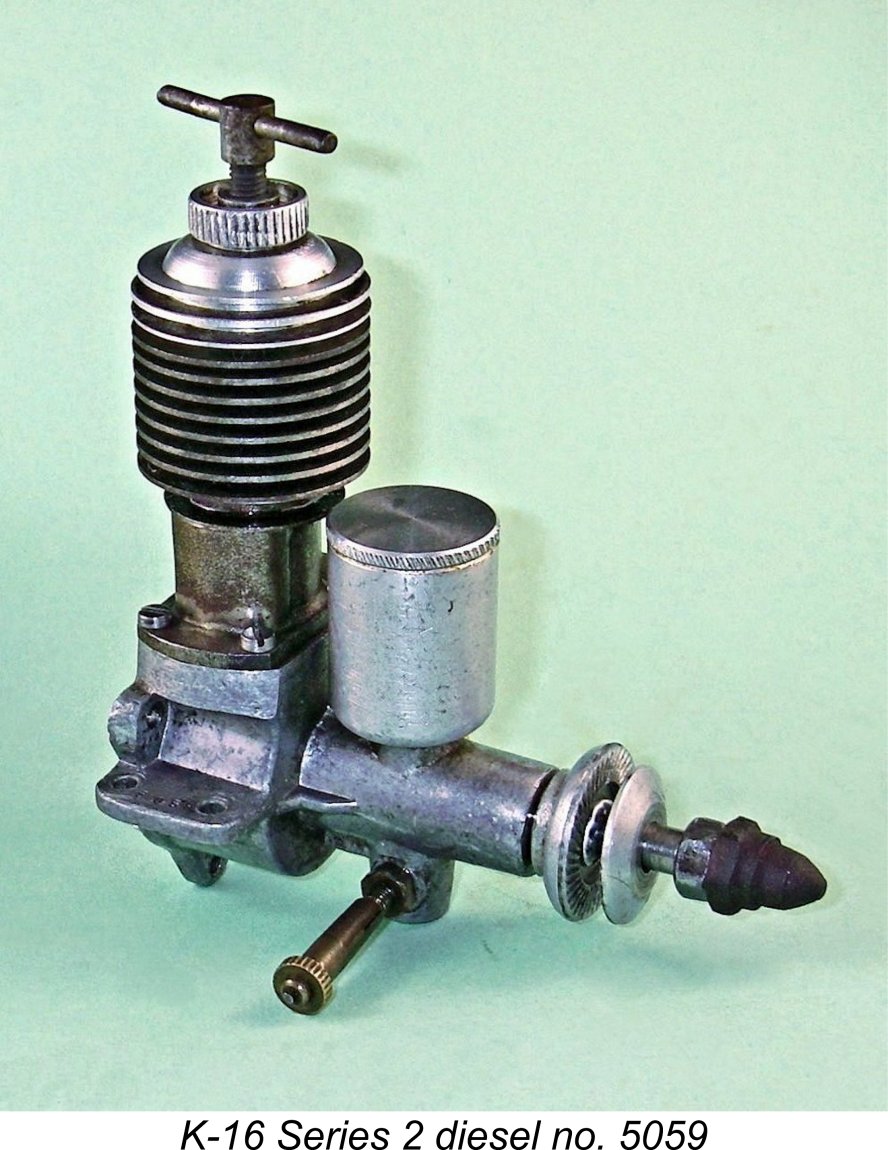
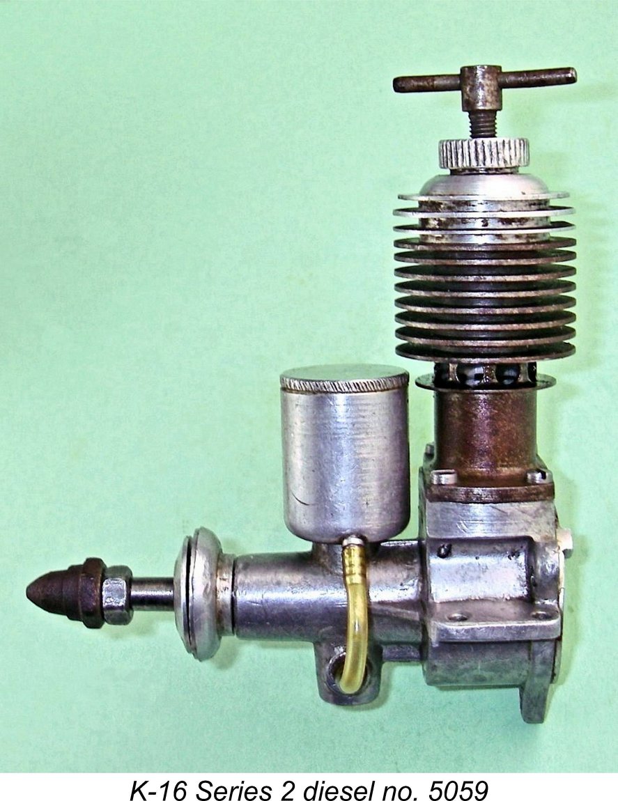
My Series 2 example is complete and original apart from having lost its exhaust stack (assuming that it ever had one, which many apparently didn’t). I suspect too that the needle valve may not be the original - although undoubtedly of Russian origin, it appears to be a standard DOSAAF assembly of the type used on various Russian engines from the late 1950's onwards. Of course, the later K-16 Series 2 units may have pioneered the use of such a fitting - there's no way of knowing for sure. The K-16 was a basically conventional plain bearing long-stroke diesel of late 1940’s style. Its main departure from typical designs of this sort was its use of crankshaft front rotary valve (FRV) induction in conjunction with updraft induction. The engine's displacement was 4.44 cc (0.271 cuin.) derived from nominal bore and stroke dimensions of 16 mm and 22 mm respectively. The resulting stroke/bore ratio of 1.375 to 1 is among the highest such ratios of my personal acquaintance. My Series 2 example weighs a hefty 245 gm (8.64 ounces) complete with tank. When one is first confronted with one of these engines, several unusual details draw one's immediate attention. All of these units were originally supplied with small metal tanks which were most unusually mounted at the front above the main bearing and directly above the carburettor. These tanks were secured by a single screw which threaded into a blind-tapped boss on top of the main bearing housing. An aluminium alloy spigot was press-fitted and swaged into the tank on one side at the base. This was connected to the fuel supply end of the spraybar using a short length of flexible fuel tubing. According to Viktor Khodyeyev, the standard tank gave a run of around 1½ minutes - perfectly adequate for free flight sport applications.
With the cap fitted, air is far less readily admitted to the tank. However, some air will still be admitted because no gasket is used to seal the cap. The result will be a very basic “scent bottle” effect in which the negative pressure required to draw air into the tank as the fuel level subsides will minimize the gravity feed effect at the spraybar. In fact, the engine will probably have to develop some suction to maintain the fuel supply. I decided that I would leave well alone pending an initial test of the engine as-is - it might be OK. I could always add a small vent hole later if required. The most obvious limitation associated with this tank is the fact that it can only be used with the engine mounted in the upright position. For sidewinder or inverted installations, one would be forced to set the tank aside. This is probably why many of these engines encountered today are missing their tanks - they doubtless saw use in mounting orientations other than upright. Since the tapped hole in the main bearing housing for the tank securing screw is blind, the engine will run perfectly well without the tank.
The compression screw is accompanied by a most convenient finger-activated knurled locking ring to retain settings one established. This is an extremely user-friendly device, being both effective and very easy to use. Others might have done well to copy! Another praiseworthy feature was the inclusion of a steel carrier at the centre of the alloy head to accommodate the compression screw thread.
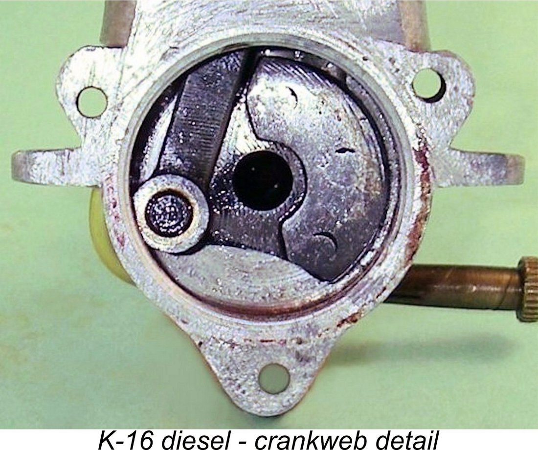
The engine utilizes a steel cylinder having integrally-formed cooling fins. Loop scavenging is employed, although the presence of a contra piston means that an upstanding baffle cannot conveniently be provided. To get around this, the piston crown on the transfer side is deeply stepped, with the transfer ports being located well down the cylinder wall to establish the appropriate timing. Many well-known diesels of the period used such an arrangement, which provides good upward direction to the incoming gas at the expense of creating a rather inefficient combustion chamber at top dead centre. The exhaust ports consist of four generously-dimensioned drilled holes. These are oriented to the left. Inspection through the exhaust ports of my example confirms that there are three transfer ports located side by side and having squared-off upper edges. They are supplied with fresh mixture through a generously-proportioned bypass passage, the outer wall of which is hard-soldered to the exterior of the lower cylinder wall. The crankcase is provided with a large cut-away in the upper deck on the right-hand side to supply mixture to the bypass. For this reason, the cylinder can only be installed with the exhaust to the left and the bypass on the right. This arrangement is readily apparent in the accompanying Exhaust timing is quite advanced for what would appear at first sight to be a relatively low-speed engine. The ports begin to open at 108 degrees after top dead centre for a total exhaust period of 144 degrees. I couldn’t measure the transfer period with any precision - all I can say is that the transfer ports seem by “feel” to open no more than 10 degrees after the exhausts. If true, this would give a lengthy transfer period of 124 degrees. At the top, the cylinder head is a separate internally-threaded light alloy turning which is screwed onto the externally-threaded top of the cylinder like a cap. It features the previously-mentioned steel insert for the compression screw thread. The cylinder is secured to the upper crankcase using four slot-head screws which pass through an installation flange at the cylinder base to engage with tapped holes in the upper crankcase. A fibre gasket is used to ensure a seal. The very heavy piston is made from gray cast iron. Four oil retention grooves are formed in its working surface - two near the top and two more near the base. The piston drives the crankpin through a milled steel rod which is fitted with The crankshaft appears to be a solid steel component featuring a crankweb which has substantial cutaways on either side of the crankpin to provide some counterbalance. In addition, the web is fitted with a separate arc-shaped counterweight which is triple-riveted to the side opposite the crankpin. It’s clear that serious efforts have been made to address the obvious vibration potential of what appears to be a relatively heavy piston/rod assembly operating over a very long stroke. The crankshaft has a measured central gas passage of 6 mm diameter. As near as I can measure it without taking the engine apart, the main journal diameter is 9 mm. This provides a crankshaft wall thickness of 1.5 mm (0.059 in.), which appears to me to be a bit on the marginal side. However, the relatively small bore and consequently reduced compression/power stroke working loads as well as the seemingly low design speed and the attention paid to vibration management may suffice to keep things together provided that the material used was of reasonable quality. I’ve never heard that these engines were known for breaking shafts.
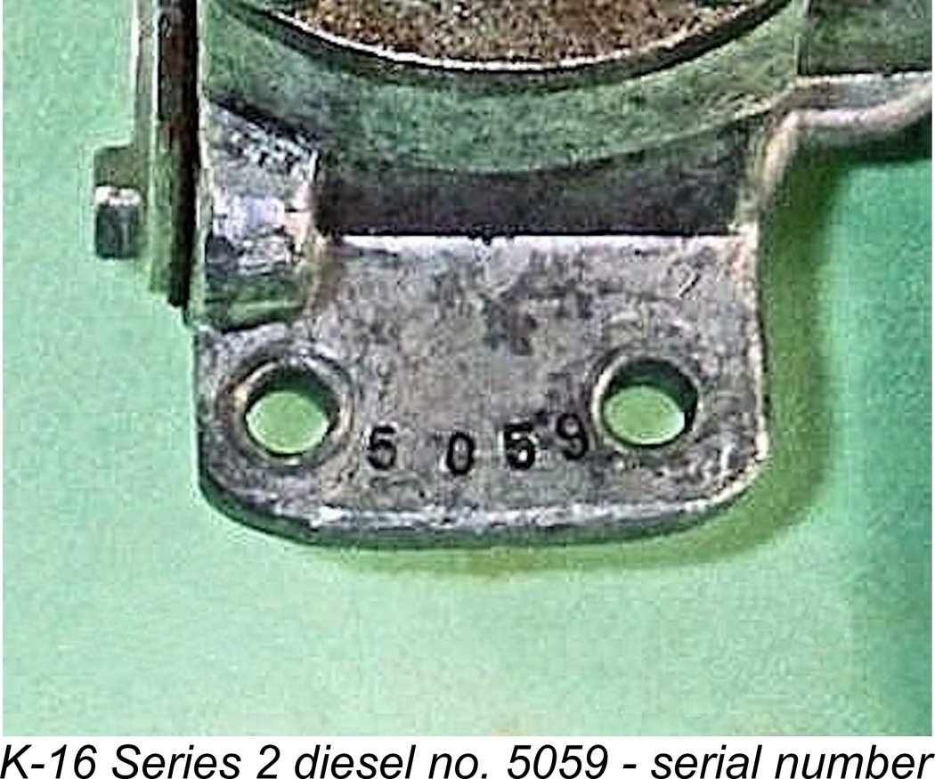
The induction system used on this second-variant example draws air though an intake having a throat diameter of 7 mm. This is supplied with fuel through a spraybar having a diameter of 4 mm. Reference to Maris Dislers’ extremely useful Intake Choke Area Calculator reveals that this combination yields an effective intake area of 12.093 mm2. For a 4.44 cc engine, the minimum operating speed for consistent performance on suction feed in a sport flying context is 9,805 rpm, a speed which this engine appears highly unlikely to attain! However, when used for free flight duration purposes where a somewhat lesser level of suction can be tolerated, the minimum speed drops to only 5,584 rpm, which seems to be well within the K-16’s reach. It must also be recalled that the engine benefits from a measure of gravity fuel feed if the standard tank is used, hence not relying upon suction feed. The standard prop retaining fastener for all engines throughout the K-16’s production life appears to have been a steel acorn nut which Many examples (including my own pair) retain their original prop fastening components, although others have lost their original fasteners, instead having conventional hex nuts and sometimes a non-standard prop driver and/or prop washer. My Series 2 example hedges its bets by having both an acorn nut and a conventional hex nut! I rather doubt that it was originally supplied in this form. My Series I example displays the serial number 23 neatly stamped onto the top of the right-hand mounting lug. This implies that the serial number sequence started at engine no. 1 - mine is a very early example. Series 1 engine no. 366 appeared on eBay in October 2024. The Series 2 example owned by former "Aeromodeller" Editor Andrew Boddington bears the serial number 1424, suggesting that the Series 1 model was manufactured in relatively smaller numbers. My Series 2 engine bears the serial number 5059, seemingly implying that at least that many were made in total. The true figure was likely considerably higher. I'd be grateful for any additional confirmed serial numbers which readers are able to supply.
The majority of these engines seem to have stayed behind the former Iron Curtain. It was not until the early 1970's that the Soviets began to make serious efforts to market Russian-made engines in other countries. By that time, the K-16 was long gone. This explains why most of them seem to have stayed home. Although the engine gives the visual impression of being a somewhat “utility grade” product, closer examination reveals it to be manufactured to a very good standard, especially where it really counts. Although no attempt has been made to tart up the engine's appearance, all key fits are excellent. My Series 2 example has clearly had plenty of use in the past, but remains in very good mechanical and cosmetic condition with tight bearings and adequate compression. A very suitable subject for a bench test, in fact - let’s get right to it! The K-16 Diesel on Test
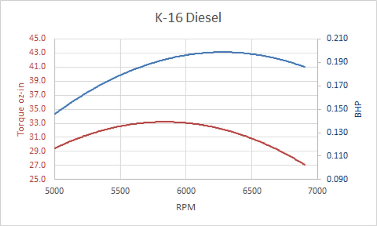
Regardless of how Chinn came up with this data, it indicated a peak output of around 0.193 BHP @ 6,400 rpm. Chinn's numbers are substantially higher than the previously-quoted figures reportedly claimed by the manufacturers. Despite this discrepancy, I have to say that Chinn's data appears to be quite consistent with the engine's main design features. I therefore decided to take Chinn's curves as my primary reference when planning this test. When approaching a test of the K-16, the first decision that I had to make was which prop to begin the test with. This is clearly a low-speed engine - indeed, the manufacturers stipulated a maximum operating speed of 6,500 rpm, with a normal operating speed of 5,000 rpm. Accordingly, speeds needed to be kept down - small props need not apply! The wooden prop supplied with the engine had a diameter of 350 mm (13.8 inches), but no pitch was specified. I decided to begin my testing with a 12x6 APC prop having plenty of flywheel but unlikely to bog the engine down unduly. My plan was to proceed to try other props once I knew how the engine handled the 12x6. As far as fuel went, my standard “pioneer diesel” brew of equal parts ether, kerosene and SAE 60 mineral oil was a whisker-close approximation of the maker’s recommended brew.
In response to this issue, I decided to use a separate fuel tank for this test session, setting the starting fuel level at or slightly below spraybar level to promote low-head suction feed. With this arrangement in place, fuel feed problems were a thing of the past. Turning the engine over compression by hand revealed that the piston/cylinder fit was worn to the point that compression seal was a little "softer" than ideal. The fact that the engine appeared to have a parallel bore with essentially no "pinch" at top dead centre doubtless contributed to this. However, there was still plenty of compression for starting and running, especially with all that gooey SAE 60 oil in the fuel mix, and a start was soon effected following an exhaust prime. Well .......... almost! Here's where things became a little weird! The engine would deliver a nice strong firing burst very readily but would quickly die away and stop. This behaviour continued no matter how I set the needle - even with the needle almost fully extracted, the engine simply wouldn't draw fuel and keep going. The symptoms were those of a too-lean needle. I checked the spraybar and its two jet holes, finding that everything was clear and in the correct orientation. This led me back to the data obtained from Maris Dislers' Choke Area Calculator as reported earlier. We saw that the set-up with which I started required a minimum operating speed of 9,805 rpm for adequate suction in a sport or bench test application. Clearly I wasn't going to get near that figure with this engine! A further check with the calculator showed that if the venturi choke diameter was reduced to only 6 mm using the same 4 mm dia. spraybar, the minimum operating speed on suction would be reduced to 5,023 rpm. This was clearly a potential solution to my problems! Accordingy, I made a venturi restrictor from aluminium alloy with an internal diameter of a shade under 6 mm.
I soon found that in keeping with many larger low-speed diesels, the compression had to be increased significantly for cold starting. The relatively "soft" compression seal doubtless contributed to this requirement. In addition, the needle valve had to be opened a little to promote good initial fuel pickup. As I had expected, choking was ineffective - any fuel drawn in simply dripped out of the updraft intake. It was absolutely necessary to administer an exhaust prime to achieve a start. Once I had all of this figured out, the engine proved to be a very easy starter indeed, needing only a few flicks to commence making noise. Once running, it kept going very dependably, waiting patiently for me to adjust both the compression setting and the fuel mixture. Response to both controls was very good, making the establishment of optimal settings perfectly straightforward. Once correctly set, the engine ran very smoothly without missing a beat. Both controls held their settings dependably - the compression locking ring was not required. The one fly in the ointment was the level of vibration, which was every bit as evident as I had expected! I quickly established the fact that the K-16 turned the APC 12x6 test prop at a smooth and steady 5,900 rpm. This seemed very promising - it was only some 500 rpm below the peak figure reported by Peter Chinn. I was clearly in the right ball-park! Guided by this figure, I proceeded to try the engine on a range of test props which I felt sure would encompass the peak. The following data were recorded.
The above data imply a peak output of some 0.185 BHP @ 6,800 rpm. This is about as close as one could reasonably expect to come to matching the figures of 0.194 BHP @ 6,400 rpm reported by Peter Chinn. I'd say that this test confirmed the validity of Chinn's figures quite persuasively. Although by no means a stellar performance for a 4.4 cc diesel by the standards of the early 1950's, the K-16 developed its power at far lower speeds than most of the competition, hence having the ability to swing a prop of really meaningful size. Its strong suit was high torque at low rpm. Its main drawback was the high level of vibration. I'd be tempted to restrict the operation of this unit to speeds below 6,000 RPM. A 12x7 or 13x6 would probably work well as flight props. Coupled with its excellent handing, I'm sure that the K-16 would have delivered full satisfaction to most of its Russian users despite the vibration issue. Indeed, Michel Rosanoff of the well-known Retroplane vintage engine history forum advised that the engine remained in quite widespread use at the club level into the early 1960's. Even as late as 1959, it was used by Boris Borissov to establish three international records (duration, distance, altitude) in the R/C helicopter category. Not bad for a ten-year-old design!
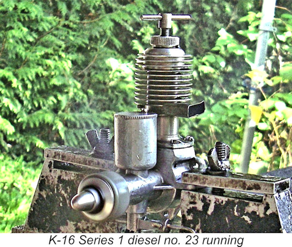
On the basis of this test, the K-16 may be summed up as a fine handling, well-made and robustly constructed unit well suited to its intended role of providing Russian modellers with the opportunity to gain experience in the design, building and flying of powered model aircraft. It's scarcely surprising that it ended up being made in such large numbers! Just for fun, I installed my Series 1 example of the K-16 - engine no. 23 - in the test stand to give it a few runs. It proved to be just as easy to start and adjust as its Series 2 companion, requiring no modification to the intake to provide adequate fuel suction. I confined my testing to an APC 12x6, which the Series 2 example had turned at 5,900 RPM. The Series 1 model got this prop up to 6,000 RPM, demonstrating that the performances of the two variants were essentially identical. Further Testing by Maris Dislers As it happened, my work on this article coincided with an offer from former “Aeromodeller” Editor Andrew Boddington to send a few of Andrew’s classic engines down to Maris Dislers in Australia for testing. One of these engines was Andrew’s example of the K-16 diesel, Series 2 engine no. 1425. I was all for Maris testing that example – two sets of test data carry far more authority than one! Maris wasted no time in getting to grips with the engine. He found it to be well gummed up with old castor oil, requiring the application of heat and solvent to free it up. Once free to turn over with a prop fitted, the engine proved to be well past its prime, with a poor piston seal both cold and hot which became worse after the last of the castor gum was completely eliminated. Nevertheless, there was sufficient compression to support both starting and running provided a fuel with plenty of oil was used. However, great care was needed to keep operating conditions within the limits in which an adequate oil seal was maintained. Maris used equal parts castor oil/ether/kerosene with 0.8% ignition improver. The engine started and ran quite happily using this very "oily" fuel. Checks with the same mix but substituting SAE 50 mineral oil also went well. Maris shared my view of the gravity fuel tank’s problematic effect upon starting. He found that the tank worked, but it was necessary to clamp off the fuel line until a firing burst was obtained, at which point the clamp was quickly released to keep the engine running. Attempts to start the engine using the "dripping nose" approach only produced a flooded/dead engine. Maris did as I had done by using a separate fuel tank set at fuel jet level. The initial run showed a misleadingly impressive 6,970 RPM on an APC 12x6 prop. However, this could not be sustained once the last of the castor oil gum had been flushed out during operation. Subsequent trials dropped this speed to only 6,200 RPM. Maris found the engine to be quite sensitive to the particular airscrew used. APC 12x8, Graupner 12.5x6 and Graupner 10x6 props all gave poor results. In particular, with the 10x6 it was not possible to push the settings beyond an under-compressed and still rich state without risking a rapid sagging and stop due to oil film breakdown causing excessive compression leakage. That said, further testing with a fuel consisting of equal parts SAE 50 mineral oil/kerosene/ether plus 0.8% ignition improver produced some representative results, since the engine was found to run quite nicely on this fuel. The following data were recorded:
As can be seen, despite its apparently worn condition Andrew’s engine appears to have out-performed my own example by a small margin – note that it turned the APC 12x6 at 6,200 RPM as opposed to my engine’s 5,900 RPM. Only 4 data points are insufficient to generate a truly representative set of performance curves, but Maris’s data imply that engine no. 1425 developed around 0.197 BHP @ 6,300 RPM, thus more or less duplicating Chinn's figures. Maris subequently tried the engine on a straight mixture of equal parts kerosene/ether/mineral oil with no ignition improver, finding the performance on the two larger props to be very slightly improved using this fuel. However, no improvement was noted for the 12x6 prop. Maris also found a scan of a Czech article discussing the engine, in which a fuel containing equal parts of gasoline, ether and mineral oil was suggested - a blend which was actually featured in the K-16's owners manual, as mentioned earlier. Such a fuel would not logically be expected to produce good results in a model diesel, which perhaps explains why both the owners manual and the Czech article cited a peak output in the range of only 0.12 BHP to 0.15 BHP, with an operating speed range of 4,000 – 4,500 RPM. My sincere thanks to Maris for providing this very useful information! The K-16 Replica
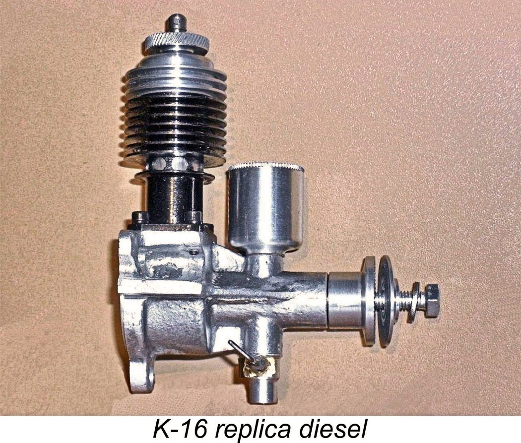
Although they don't appear to be very common (hence almost certainly being collectibles in their own right), examples of the replica appear from time to time on offer through eBay or other marketing venues. Based on the images that I’ve been able to track down on the Internet, it seems that there’s little danger of mistaking the replica for the real thing. To start with, the replica has an extended alloy prop driver and uses a steel bolt which threads into a tapped hole at the front of the shaft to secure the prop. The extended male thread and acorn nut used on the originals are very conspicuous by their absence.
The replica’s exhaust ports are located on the right-hand side of the cylinder instead of the left-hand side as featured in the originals. The upper crankcase deck must be cut accordingly. Moreover, the clamp-on exhaust stack appears to have been omitted. The cylinder is chemically blackened and is secured to the crankcase using socket-head screws instead of the original slot-head items. Finally, the single-armed compression screw is very different from that used on the original K-16 engines. Overall, there are more than enough obvious departures from the original engines to enable anyone having a little knowledge of the original K-16 to spot a replica instantly. I’m sure that won’t stop some people from trying it on, but you have now been forewarned and forearmed! Mind you, as I said earlier, the K-16 replica is almost certainly a desirable collectible in its own right! My only concern is that if it's a replica, it should be described as such. Conclusion It's clear from the above account that Russian modellers of the early to mid 1950's were well served by the availability of the K-16. The engine must have played a key role in advancing DOSAAF's strategy of popularizing power aeromodelling among Russian enthusiasts and thereby promoting the development of skills which would serve the State well in other areas. Although the engine was no ball of fire in performance terms, it was a sturdy, well-made and fine-handling unit which must have provided its users with dependable power for a variety of models. There's little doubt that it fully justified its development and widespread distribution. I hope that you've enjoyed this look at a genuine Iron Curtain classic! No-one who appreciates model diesels could fail to enjoy an encounter with one of these excellent powerplants! I certainly enjoyed my own experience........... _________________________ Article © Adrian C. Duncan, Coquitlam, British Columbia, Canada First published November 2024 |
||
 In an
In an 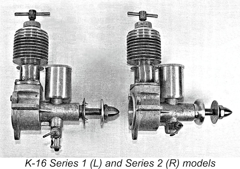 The K-16 was produced in two distinct series, although the differences were very minor, being confined to a few details. Viktor Khodyeyev's accompanying illustration at the left should clarify the differences. The earlier Series 1 version featured a nickel-plated steel cylinder, while the cylinder of the Series 2 model was left plain as machined. The Series 1 variant had a separate steel “throttle” unit incorporating a rotary adjustable air intake to allow a measure of pre-flight speed control. The rotating air metering sleeve had a serrated edge and was retained by a flat leaf spring which also stabilized its rotational setting. This model used a steel prop driver having two pointed protrusions for grip. My own Series 1 example is missing the air metering sleeve, which I suspect may be a fairly common situation with these engines. To make up for this, it retains its exhaust stack!
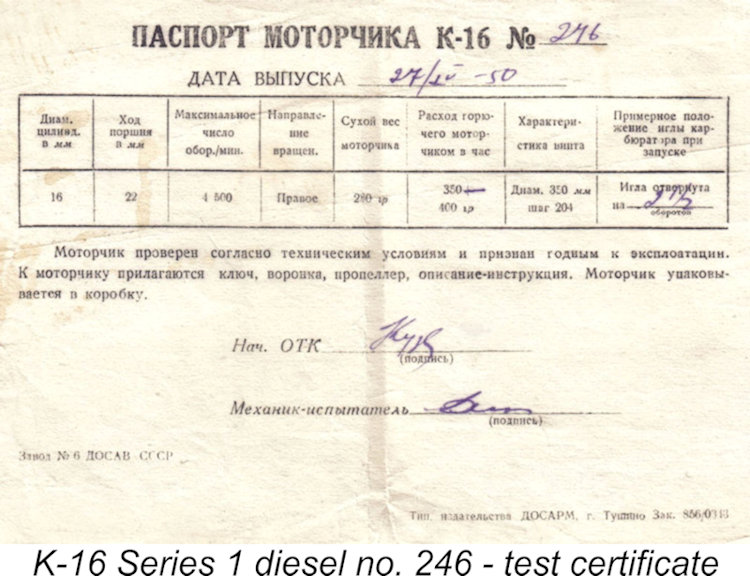
 The engines were supplied with an extremely detailed 18-page owner's manual. Much of this document consisted of a detailed summary of the operating principles of a two-stroke model diesel engine, emphasizing the educational objectives which promoted the K-16's production. Each engine was also accompanied by a test card on which the starting settings established during the engine's factory test were recorded. My sincere thanks go to my good mate Peter Valicek for his kindness in sending me a scan of these documents along with an English translation.
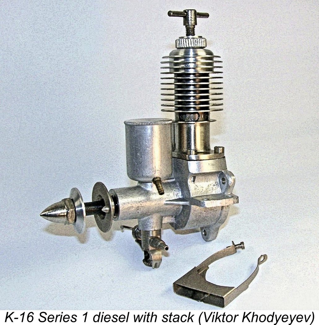
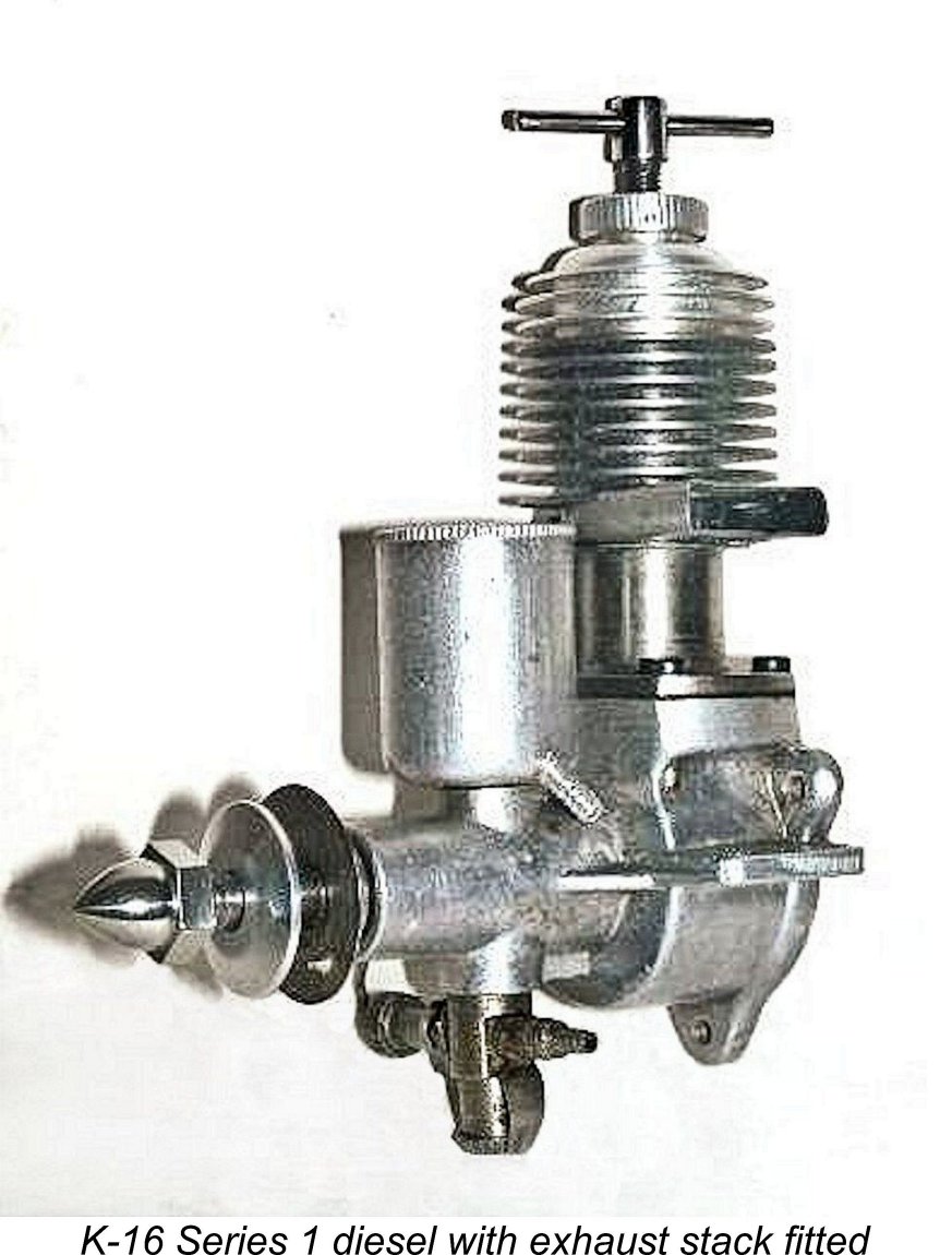 My own previously-illustrated example of the K-16 is a later Series 2 model with the simple carburettor and alloy prop driver. The attached image at the left shows a complete K-16 Series 1 unit with its clamp-on exhaust stack fitted. My own Series 1 example retains its stack but has lost its air-metering control.
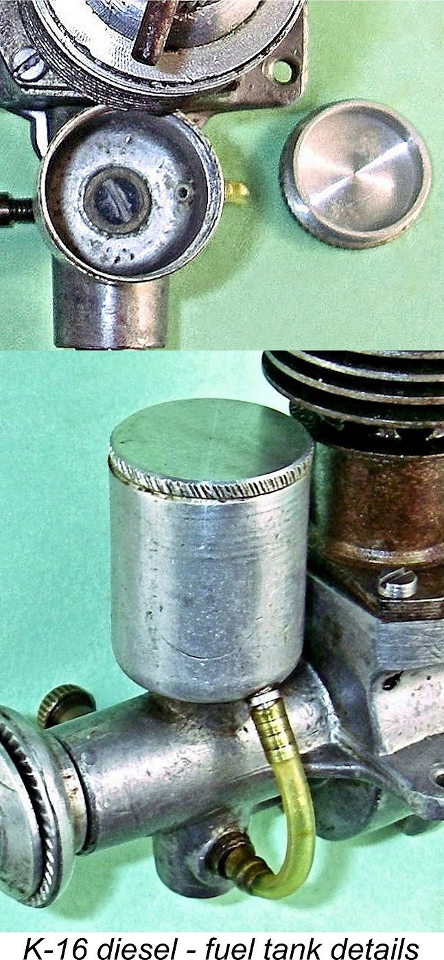 The tank was closed at the top by a full-diameter screw-in cap. Oddly enough, this was not provided with an air bleed hole to admit air as the fuel level went down. I was contemplating adding such a hole when I started to think a bit harder about this omission. As fitted, the tank will create a substantial fuel head to supply the carburettor by gravity. If left unrestrained, this would drain the tank in short order when the engine was fueled but not yet running. Moreover, the change in fuel head during the run would be quite dramatic.
 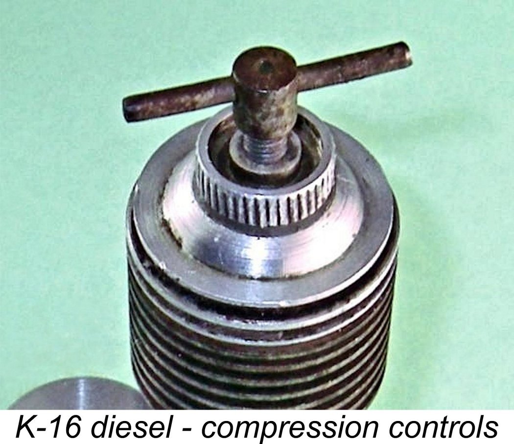 Apart from the unusual tank location, the other feature which immediately attracts attention is the compression control system. A variety of compression controls have been seen on these engines, from ordinary T-profile components as on my examples to Y-profile controls and even single-arm fittings. However, it appears that the T-profile component was used on all examples as originally supplied.
 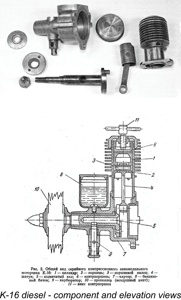 I’ve chosen not to disturb this used and seemingly well run-in example beyond removing the backplate to have a quick look inside. However, my own observations combined with the comments of Viktor Khodyeyev allow me to describe the engine quite comprehensively. Viktor’s accompanying component view along with the attached General Arrangement (GA) drawing should help to clarity the following description.
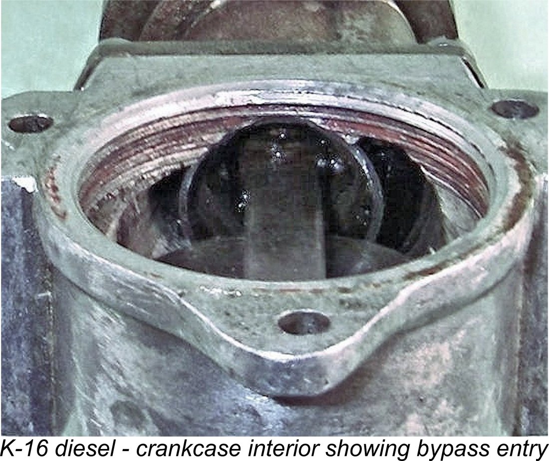
 The crankshaft induction port is a simple round hole. As with the exhaust and transfer, the induction period provided in this design is surprisingly generous for a low-speed unit. The crankshaft induction port opens at 35 degrees after bottom dead centre and closes at 15 degrees after top dead centre for an induction period of 160 degrees. It’s interesting to note that the opening of the induction port appears to precede the closure of the transfer ports by possibly as much as 37 degrees. This means that when the transfer ports finally close and crankcase de-pressurization can begin to draw in fresh mixture, the induction system is already wide open - perhaps not a bad thing. There is no supplementary sub-piston induction.
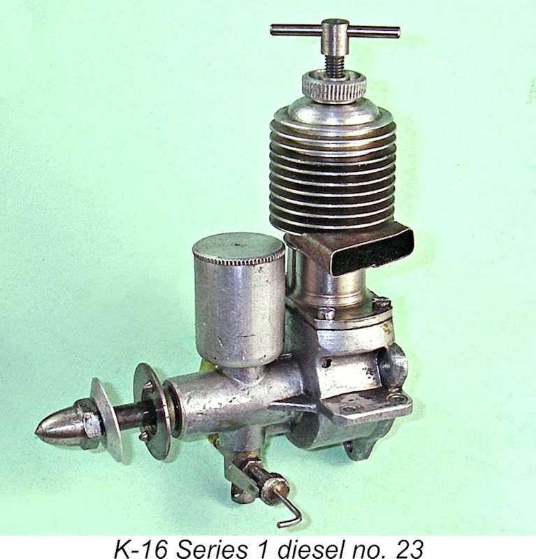
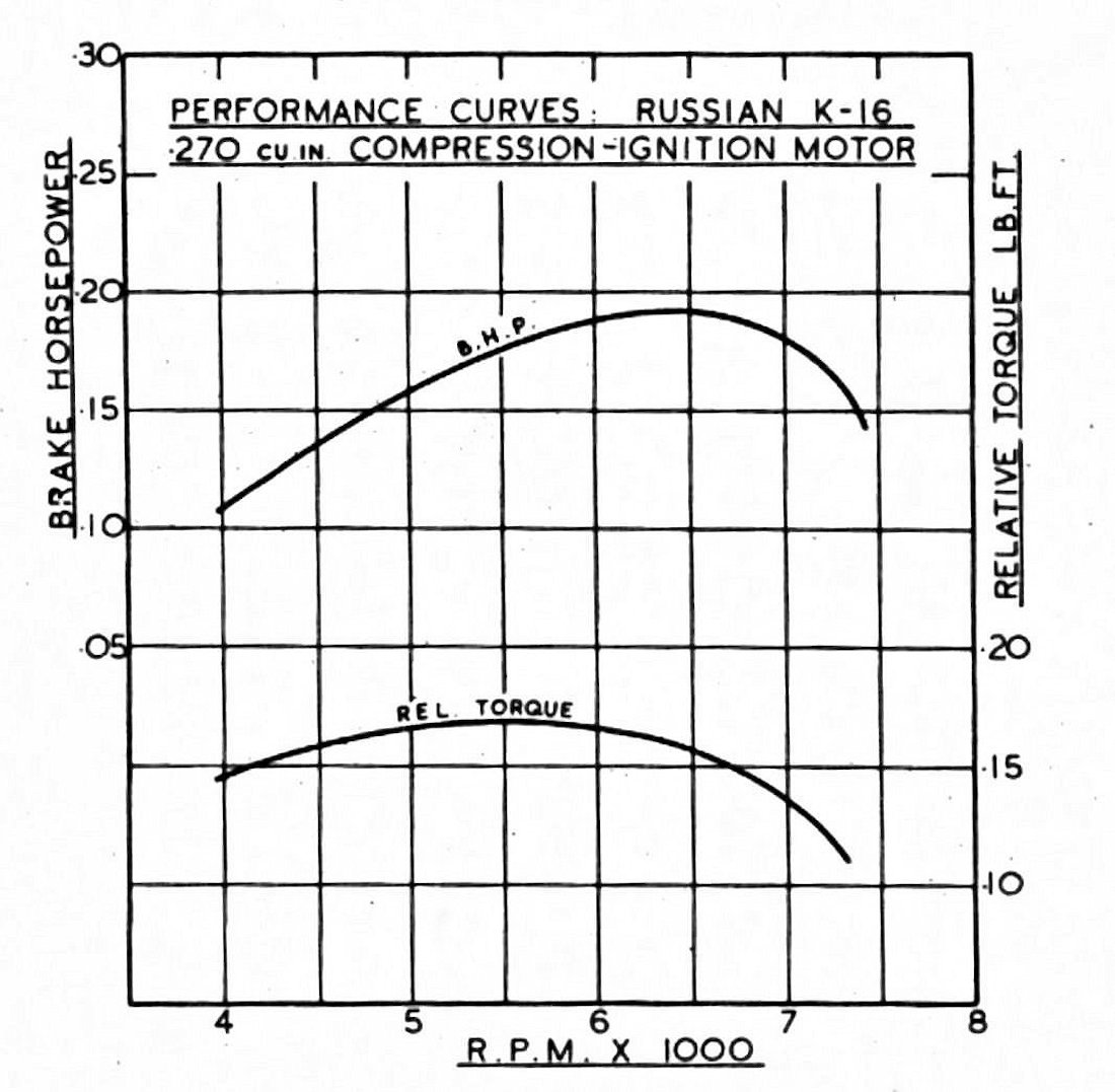 Somewhat intriguingly, Peter Chinn included a set of English-language power curves for the K-16 in his previously-mentioned September 1953 MAN article about then-current Russian engines. I have no idea how he came up with this data, which is reproduced here. It may be that he took a set of Russian-language curves and re-drew them with English units and notations. Or perhaps he somehow acquired an example to test himself. We'll never know............
 With the engine set up in the stand, I quickly ran into a problem with the fuel supply arrangements. Using the built-on gravity feed fuel tank, the fuel immediately began to drip out of the updraft intake, lowering the level of fuel in the tank quite rapidly. Basically, after filling the tank and replacing the screw-on cover, one had very little time to get the engine going if a run of reasonable length was to be achieved. In addition, the wastage of fuel was highly undesirable. The tank worked OK, but it was necessary to achieve an immediate start after filling.
  With this restrictor fitted, I returned to the fray. Happily, the problem was fully sorted - the engine would still deliver a firing burst in very short order, but now it would keep going. With the engine now set up to start easily and run steadily, it was possible to become more familiar with its handling characteristics.
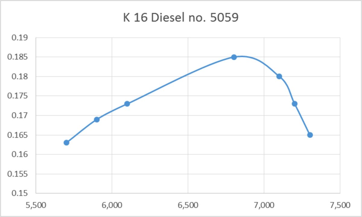
 The fact that relatively few examples of the K-16 appear to have migrated out of the former Soviet Union to other countries naturally created a demand for a well-produced replica of the engine. Such a replica duly appeared, although at present I have no idea where, when or by whom this engine was made. All I know is that the instigator of these replicas wasn’t Arne Hende - he never organized the production of a K-16 replica. Can any reader clarify this point for us?!?
 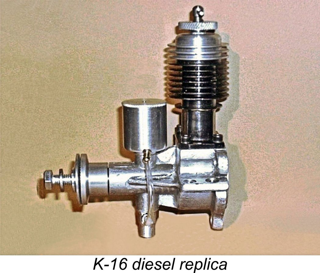 The replica’s crankcase appears to be more massively cast, with noticeably thicker beam and radial mounting lugs. The carburettor is a hybrid falling between those of the two original models - it has the vertical length of the earlier original “throttled” variant but lacks its rotary air control. The replica's compression locking ring is thinner and of larger diameter than that featured on the original.
 | |