
|
|
An Oddball Obscurity - the GLOGO 45 Glowplug Motor
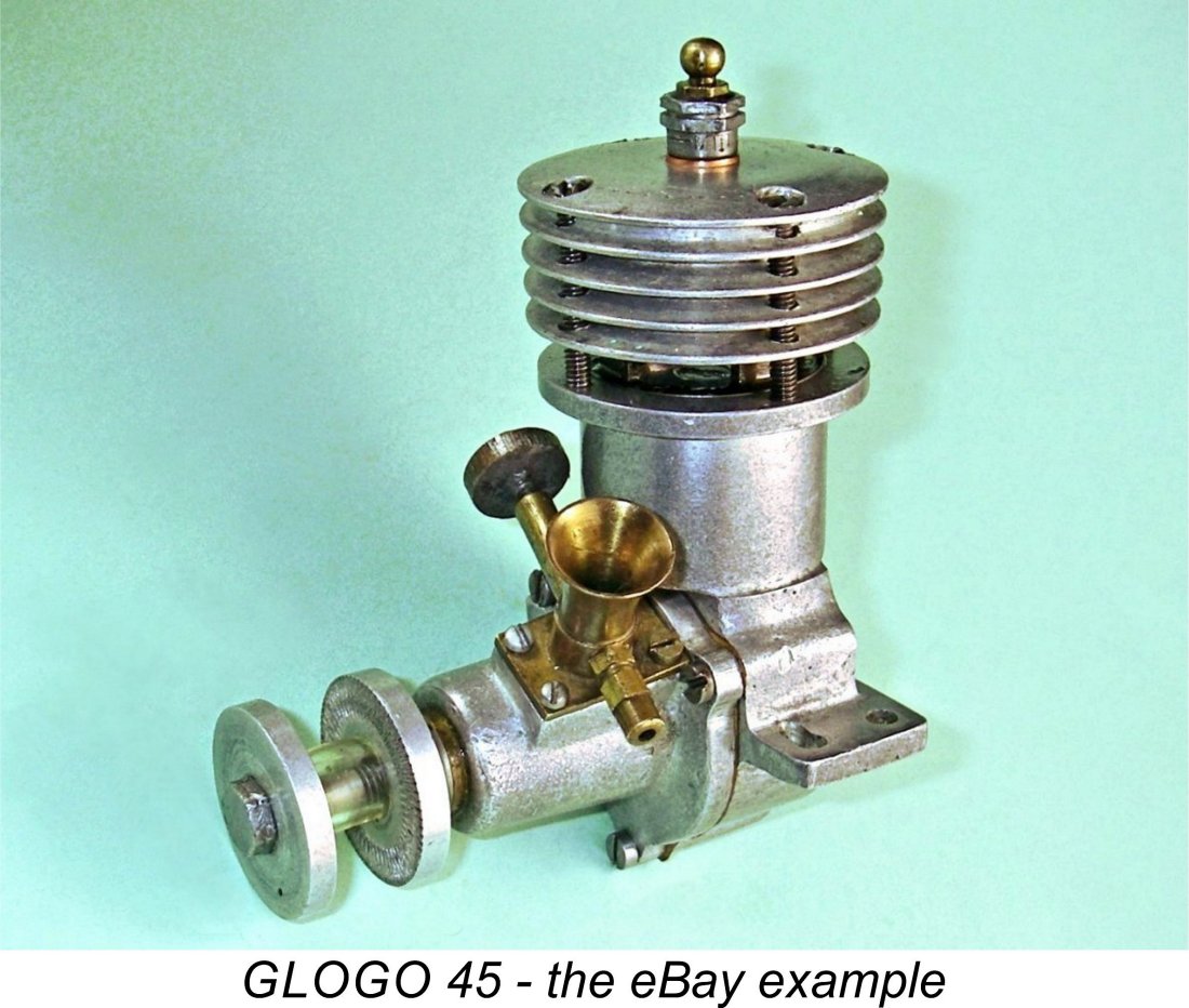
The subject of the present article falls squarely into the latter camp! I know its name, since that name appears neatly stamped in two locations on the engine. I know its displacement. I even know its serial number. However, I have no definite knowledge whatsoever regarding its source. I don’t even know its country of origin for sure, although I can make an educated guess. I don’t normally publish articles covering odd-ball engines about which so little is known. However, this one looked to me like a valid exception to the usual rule - we know its name and also know that it exists in more than one variant (see below). This implies that a higher than normal level of design development went into its creation - it's not a one-off. It’s also extremely well made, added to which the maker was sufficiently satisfied with the result of his efforts to give it both a name and a serial number. Accordingly, I saw value in publishing an article in the hope that it might trigger someone’s memory. But I’m getting ahead of myself! In March 2022 I stumbled across an eBay offering of a self-identified glow-plug engine of which I’d never heard - a fairly rare occurrence! Even Mike Clanford and Ted Sladden missed this one in their respective books, and between them they didn't miss much! The engine was identified on the case in two locations as a GLOGO unit, a name completely unfamiliar to me. Accordingly, this engine is not a Wotizit - it’s a Whenwuzzit, Wherewuzzit and Whodunnit!
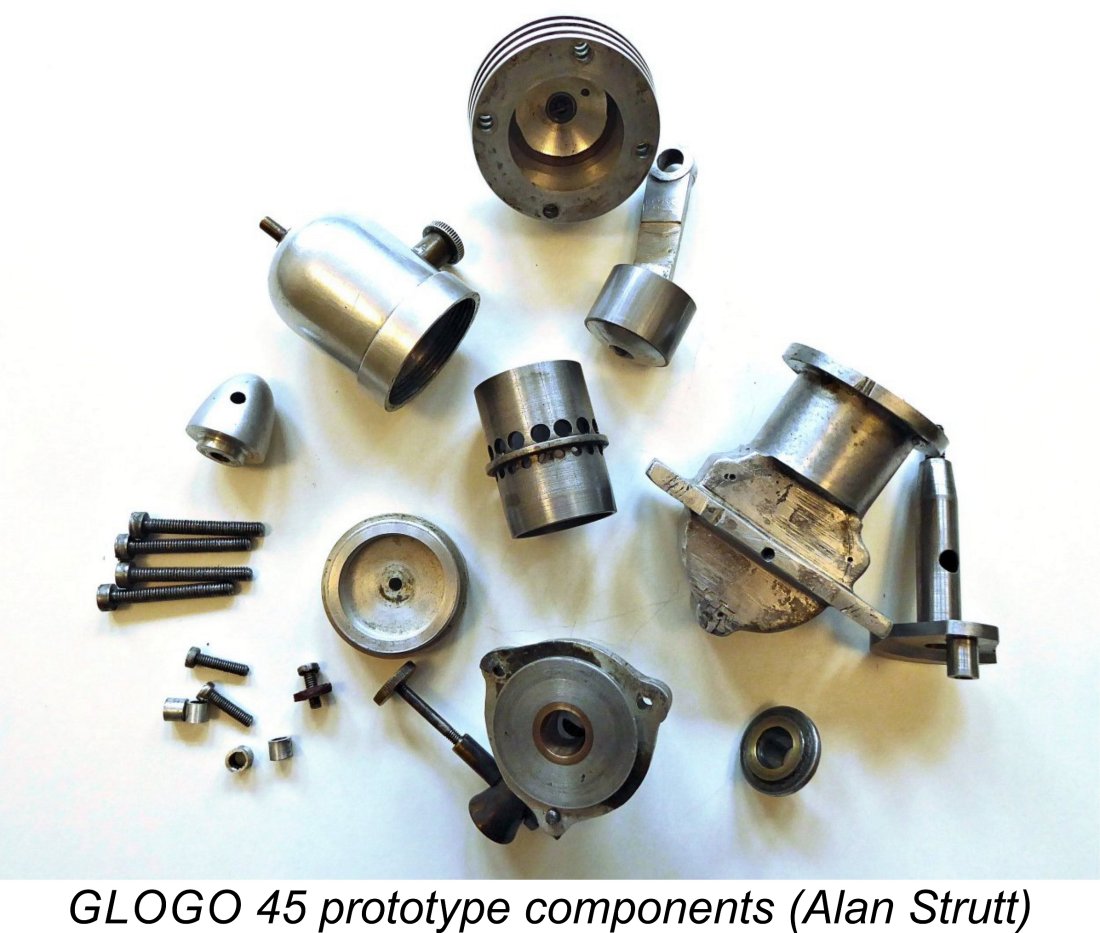
The design of this engine greatly intrigued me, as did its potential source! It clearly dated from relatively early in the glow-plug era - the style of cylinder porting and the general arrangement both attested to that. It was definitely not an American design - it displayed far too many departures from the design conventions for American non-racing engines which were established early in the glow plug era. Nothing even remotely like this ever came out of an American workshop. The intriguing separate brass bolt-on intake venturi seemed to suggest that the engine might have a Japanese origin - the radial cylinder porting and three-point front housing attachment would be consistent with that idea. However, the rather massive style of the sand-castings seemed inconsistent with such an origin - Japanese designs of the period with which we appear to be dealing were typically based upon far less massive castings, in accordance with the minimalist design philosophy which prevailed in that country at the time. As I’ve done a few times in the past, I allowed my curiosity to get the better of me and bought the engine as a bit of an enigma warranting closer study. I’d previously had a number of satisfactory dealings with the While awaiting delivery of my purchase, I decided to contact my English informant Alan Strutt. Alan is extremely knowledgeable about early Japanese engines, leading me to believe that he might be able to comment on the possibility of the engine having a Japanese origin. I sent him some of the eBay images for his perusal. As it turned out, I hit pay dirt! Not only did Alan have a number of pertinent comments, but he actually owned an engine which was very clearly related to the GLOGO despite lacking any identification as such. Upon receipt of my inquiry, he was kind enough to dismantle his engine to take some measurements and provide photographs of the engine and its components. Once the eBay example arrived, it was found to embody a number of quite distinct design features despite the very clear relationship between the two engines. In the following description, I’ll highlight these variations. This section of the article was greatly informed by Alan’s much-appreciated comments. The GLOGO Twins - Description
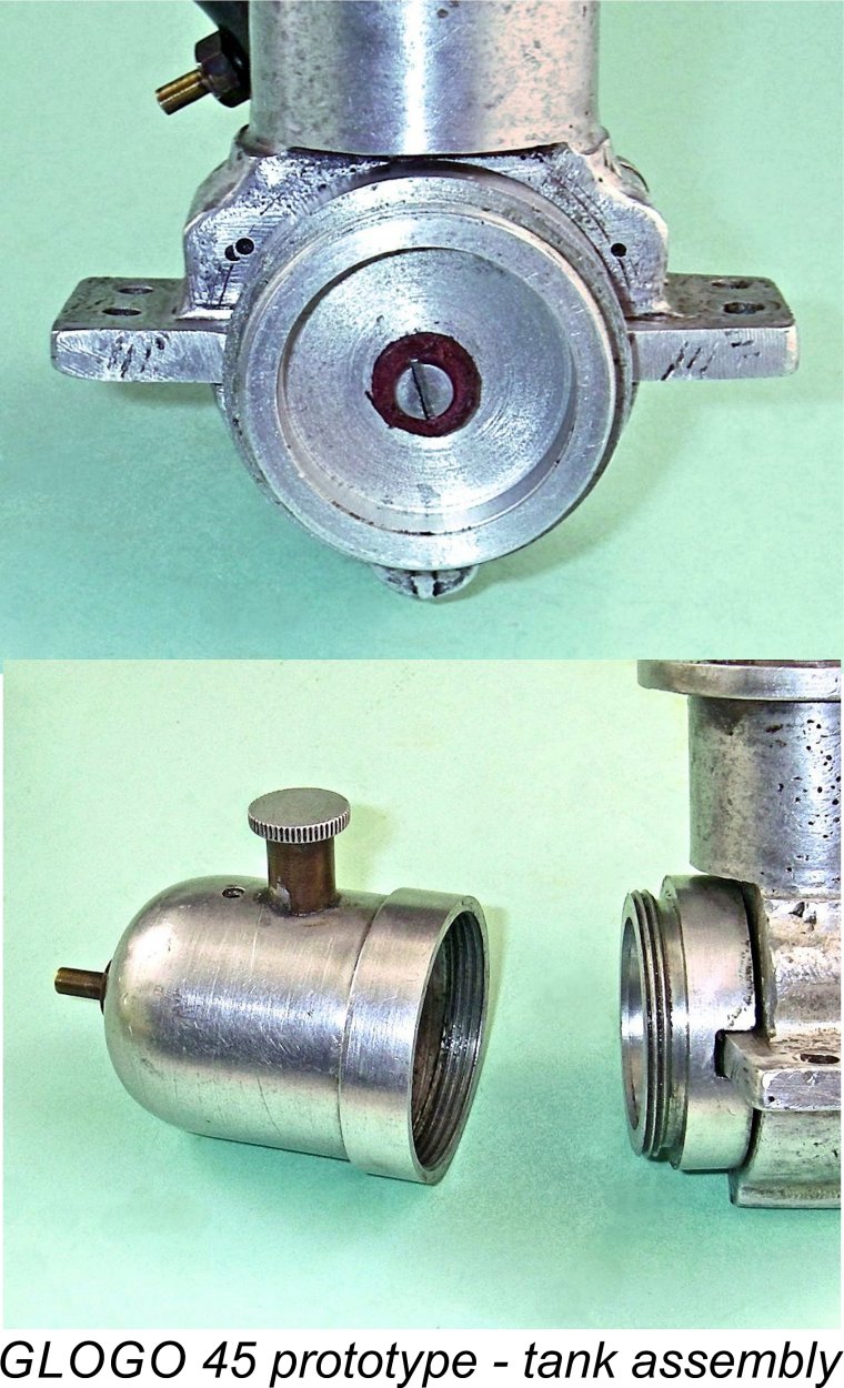
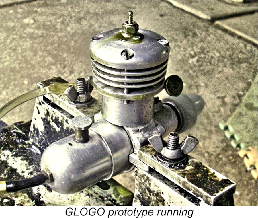
For starters, Alan’s example sports a fuel tank. However, Alan’s own assessment was that this tank was an afterthought - the integrally-cast back-plate with its transverse stiffening web was clearly not originally designed to accommodate a tank. The tank on Alan’s engine is a well-made and very ingenious self-contained two-piece arrangement specifically slotted to accommodate the stiffening web. The tank assembly is secured to the backplate using a single 6BA machine screw which engages with a tapped hole in the centre of the stiffening web. By contrast, the self-identified eBay GLOGO seemingly never had a tank – there‘s no tapped hole for the retaining screw in the transverse web. It seems quite likely that Alan’s engine also lacked a tank when originally constructed - I agree with his assessment that the tank appears to be a later add-on feature, perhaps by a subsequent owner other than the original manufacturer. The cylinder porting arrangements too are quite different. The eBay engine has very large rectangular-cut radially-disposed cylinder ports as opposed to the Yulon-style multiple drilled holes featured on Alan’s example. The cylinder head is also different – Alan’s engine has a bi-metallic two-piece machined cooling jacket with fewer cooling fins, while the eBay example is machined from a casting as a single component, with a It’s quite beyond argument that the two engines are from the same original source. Alan and I were in agreement that his example is very likely the earlier of the two – a straw in the wind in that context is the very fact that the eBay engine bears a name which is neatly stamped on it in two locations. This suggests that the maker viewed it as the “final” version, hence including a name on the castings and also applying a serial number. It would be logical to assume that he might not have bothered doing so for an earlier prototype, which Alan’s engine seems to be. Further evidence is the more sophisticated cylinder porting of the self-identified GLOGO as well as its use of a more heavily finned cooling jacket of somewhat different design (see below). For clarity, I've elected to refer to Alan's engine as the "prototype" in what follows, recognising the fact that this characterisation is presently unconfirmed. Its companion is referred to as the "eBay" example. Alan was kind enough to take his engine apart for examination and measurement. His first observation was the engine’s use of very British BA threads throughout. The cooling jacket retaining fasteners are 4BA; the front housing fasteners and tank fastener are 6BA; the cylinder head insert retainers are 10BA; and the prop retaining stud is 2BA. Right away, this argues very strongly in favor of a British or Commonwealth origin for the engine. Both the threads and the style of the castings together pretty much rule out a Japanese origin.
Following the arrival of the eBay example, I confirmed that it shared the same nominal bore and stroke dimenions as its companion. It was found to have measured bore and stroke dimensions of 0.876 in. (22.25 mm) and 0.745 in. (18.92 mm) respectively for a displacement of 7.36 cc (0.449 cuin.) as opposed to the 7.29 cc (0.445 cuin.) of Alan’s engine. Clearly the same nominal Imperial dimensions were applied to the design of this example also - the minor differences must be down to "lathe operator's license"! Not unexpected with a pair of individually-produced artisan-built engines. Both examples of the engine are built up around two seemingly identical main castings - the crankcase and the front housing. Both components are produced by sand-casting to a very good standard, although the eBay example has a superior finish. The castings are very capably executed, including the installation of a bronze main bearing bushing in the front housing. The main crankcase casting incorporates the backplate in unit together with its transverse stiffening web. This component shows a considerable amount of after- Beginning at the top, Alan’s engine features a fully machined cooling jacket with a separate machined steel insert incorporating the installation thread for the glow-plug. A fibre gasket is used to ensure a seal. The steel insert is centrally drilled and tapped for a standard long reach ¼-32 glow-plug. The design of this insert is most unusual. To begin with, it is inserted from the top! In side profile it has a T-shape, with the stem of the T being a tight fit into a hole in the centre of the alloy head. The thin circular flange which completes the T fits into a shallow depression of appropriate diameter on the top of the head. The insert is held in place by two short 10 BA machine screws which pass through holes in the flange to engage with tapped holes in the alloy head beneath. A tentative attempt to remove the insert was unsuccessful, leading me to wonder if it might be wedged into a shallow taper. All I know is that the seal appears to be very secure - there’s probably a gasket under the flange. By contrast, the self-identified eBay GLOGO sports a cooling jacket/head which is machined in one piece from a casting, with no separate insert. This jacket also incorporates a greater number of cooling fins. Both heads feature a conically-domed combustion chamber with no squish band. Compression ratio is surprisingly high - Alan assessed the geometric compression ratio of the prototype example as being around 9 to 1, a figure which I was subsequently able to confirm. The seemingly later eBay example has a checked compression ratio of 8.75 to 1 - little different from that of its stablemate. The cooling jackets of both engines are secured with four long machine screws which engage with tapped holes in the upper crankcase deck. Alan’s example uses 4BA fasteners, while the eBay engine uses 5BA threads. The jacket of Alan’s engine is a snug fit around a steel cylinder liner which is located at the top of The cylinder porting in Alan’s example is very reminiscent of that used both by Micron and Yulon in the late 1940’s and early 1950’s. Both transfer and exhaust ports consist of 360 degree rings of drilled round holes, those for the exhaust being somewhat larger. Rather strangely in view of the generally high standard of construction, the individual spacing between adjacent holes isn’t quite uniform, reflecting slightly sloppy use of the dividing head.
One look at the cylinder porting of the two engines will be enough to convince you that both examples featured an unusually lengthy blow-down period. In order to provide an adequate transfer period, the designer elected to have the exhaust ports open extremely early. While he had the eBay example in his hands to undertake the necessary repair (see below), my good mate Peter Valicek was kind enough to develop a timing diagram for the engine, as reproduced below at the right.
The very early opening of the exhaust ports after top dead centre has another potentially significant effect. Actual compression of gas in the upper cylinder can only commence after the exhaust port closes on the compression stroke - very late in this case at 85 degrees after bottom dead centre, at which point the compression stroke is almost half-completed. Moreover, the volume of gas available to be compressed is limited to the total volume of the cylinder above the top of the exhaust port, which will be considerably less than the volume above the piston at bottom dead centre. However, the combustion chamber volume at top dead centre remains unchanged. It follows that if we take the volume of the cylinder above the exhaust port (including the combustion chamber volume) and divide that by the combustion chamber volume alone, we will derive a significantly reduced compression ratio, but one which nevertheless more accurately reflects reality in terms of the degree to which gas is actually compressed during operation. This is termed the effective compression ratio. In the case of the GLOGO, this figure will be considerably less than the 8.75 or 9 to 1 figures cited earlier for the measured geometric ratio. The problem with effective compression ratio is that the cylinder pressures that it theoretically produces at top dead centre aren’t necessarily realized during operation of a given engine. Indeed, they may not even be constant! They can be affected by such factors as temperature, ambient atmospheric pressure, oil content in the fuel, engine speed, related changes in scavenging efficiency and the use of tuned pipes or superchargers to elevate the induction pressure in the cylinder. The actual operating compression ratio, termed the dynamic compression ratio, may therefore vary somewhat from the theoretical effective ratio. For this reason, almost all model engine manufacturers take the easy way around this issue by routinely quoting the geometric compression ratio when characterizing their designs, since that is a fixed design characteristic. Long usage has more or less conditioned users to compare engines on this basis. I generally adhere to this protocol in my articles while recognizing that it does not represent reality. The other implication of such a long blowdown period is the fact that during the 30 degrees of crankshaft rotation after the transfer ports close, the exhaust ports remain open. It follows that any fresh mixture displaced by the rising piston will simply escape via the exhaust ports, thus also escaping involvement in the combustion process. It should be obvious that the potential loss of fresh mixture is considerable.
The piston assembly in the eBay engine is basically similar, but the working piston sleeve is made from steel rather than cast iron, with extremely thin walls. The screw which keeps the whole assembly together has a flat head of somewhat larger diameter which is smoothly recessed into the alloy crown. It must be said that this assembly is more elegant than the earlier arrangement as well as being considerably lighter. Presumably this modification was motivated by a desire to reduce reciprocating weight. The sturdy con-rod is fairly basic, being very nicely machined from light alloy with no bushings at either end. In Alan’s 45 prototype, the front face of its rectangular column is recessed to provide clearance for the crankweb counterweight at and around bottom dead centre. This may be seen very clearly in the previously-reproduced component view of this engine. The rod of the self-identified GLOGO 45 example is somewhat lighter in section, eliminating the need for a clearance recess.
The shaft in Alan’s example uses a perfectly round induction port, while that in the eBay example features an elongated “race track” aperture which should give more rapid opening and closing of the system. This looks like a technological evolution which is consistent with the previously-stated impression that the eBay example is the later of the two. As can be seen from Peter Valicek's previously-reproduced timing diagram, the induction timing is unusually aggressive, opening at only 10 degrees after bottom dead centre and remaining open for a full 220 degrees thereafter. Once again, a higher than usual operating speed may be anticipated. An oddity connected with this engine is that while the induction port in Alan's engine is timed for conventional operation, the shaft in the eBay example is timed for reverse (left hand) operation in a clockwise direction viewed from the front. As of 1948-49, when I suspect that these engines were created, many people were used to (sideport) engines which ran in either direction. Indeed, some users evidently preferred operation in the reverse direction to the familiar anti-clockwise mode. Consequently, a surprising number of rotary valve engines of the period were timed for reverse operation - my collection includes a number of examples from a variety of sources. While it is very well made out of good quality steel, the shaft isn’t hardened - a bit odd considering the fact that the builder went to the trouble of hardening the steel cylinder in the 45 prototype. The use of a 9/32 in. dia. central gas passage in a 3/8 in. dia. main journal leaves a very minimal wall thickness for an engine of this displacement. We might expect crankshaft integrity to be an issue with this design, even running on glow-plug ignition.
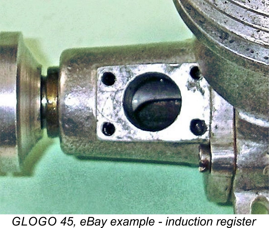
One of the most interesting features of both engines is the design and orientation of the intake assembly. Both examples use a separate bell-mouthed brass induction tube which is equipped with an integrally-formed rectangular flange at its base. The front housing is provided with a corresponding rectangular surface around the induction passage onto which the brass venturi is located. Very unusually, the location surface is machined to tilt the intake some 30 degrees to the left.
The possible motivation for this very unusual intake orientation warrants some consideration. By far the most likely explanation that occurs to me is the fact that with this intake alignment and a three-bolt front housing attachment, removing the housing and re-installing it rotated 120 degrees in the appropriate direction would allow reverse operation with very similar induction timing. Some evidence of development is seen in this section of Alan’s engine, once again implying its probable prototype status. What appears to be the original intake (which is still with the engine) was secured by only two machine screws placed fore and aft in the installation flange. This intake featured an externally-threaded spraybar, presumably for use with a split thimble on the actual needle. It appears that this was supplanted later by the presently-fitted component which uses four retaining screws like the eBay GLOGO, along with an internally-threaded spraybar. Consequently, the front housing of Alan’s engine has six drilled and tapped holes in the intake mounting area, only four of which are used. As previously mentioned, this may be another indication of the engine's prototype status.
The tank on Alan’s engine is a well-made and very ingenious self-contained two-piece assembly specifically designed to accommodate the backplate’s stiffening web. Alan’s own assessment was that this tank was an afterthought - the integrally-cast back-plate with its transverse stiffening web was clearly not originally designed to accommodate a tank. I agree with this assessment.
What appears to be the tank retaining stud at the rear is actually the fuel delivery pipe! To say the least, this is an unusual arrangement which creates some difficulties with respect to fuel line routing. The one clear advantage is the fact that the fuel pickup can easily be placed at any desired location inside the tank. This was presumably the motivation for this unusual arrangement. Alan’s engine shows signs of having undergone considerable running time, with consequently slightly “soft” compression. In some ways this is a positive indication - it seems to prove that the engine performed well enough to justify an extended period of use, likely including time spent actually powering models. It’s the good ‘uns that get the running time!! By contrast, the eBay GLOGO appears little used with excellent compression, although the elongated front pair of mounting holes suggests that it has been mounted in a model at some point.
While still awaiting the receipt of the two engines, I put out a few feelers to Australia to see if anyone down there knew anything about the origin of these units. This inquiry drew a blank - the GLOGO name is not attested in the Antipodean record, nor is it recalled by anyone down there. A similar inquiry to knowledgeable sources in New Zealand likewise came up empty. Moreover, my own in-depth research into Canadian model engine history has turned up no references to the engine. This pretty much confirms the GLOGO as being of British origin - it’s the only credible source left! The one straw in the wind (and it is no more than that) is the existence of a series of advertisements placed in "Aeromodeller" during 1948 by a firm called Super Model Aircraft Equipment of 28/39 Queens It would seem to be a logical progression to go further by adding an engine called the GLOGO to their list, and that may have been their intention. If so, this would position the GLOGO as an initiative relating to this company's marketing strategy, although such an engine never seems to have appeared in their advertising. As I said, a mere straw in the wind with absolutely no hard evidence to back it up, but a possibility nonetheless - the time, place and nomenclature are all consistent. My thanks to my Aussie mate Gordon Beeby for bringing this possibility to my attention. OK, so we still don’t know who went to the considerable trouble to design and construct these engines to a very high standard. However, we can at least see how well he did in terms of the GLOGO’s design! Off to the test stand …………. The GLOGO on Test As stated earlier, eBay GLOGO no. 10 had been found to be inoperable as received due to the fractured cylinder location flange. However, I'm fortunate enough to have some very supportive friends, among whom I'm glad to acknowledge Peter Valicek of the Netherlands. Peter is an amazingly talented model engineer as well as a good mate, and he was kind enough to agree to make a replacement liner for me out of hard cast iron. He did his usual fine job of this, returning the engine to first-class running condition. Thanks, mate! As mentioned earlier, this example is timed for reverse operation. I don't have a set of calibrated left-hand props, although I do have one or two such airscrews which should match the performance of an engine of this specification and displacement. The prototype example provided by Alan remained in good operating condition despite its slightly soft compression, also being timed for operation in the conventional direction. I decided to begin the testing by giving it a go on the test bench. I used a modern glow-plug in order to conserve the still-functional KLG Miniglow plug with which the engine was fitted. The fuel was a 5% nitro castor oil-based blend. A problem which reared its ugly head immediately was the fact that the prop driver's hub had a diameter of a whopping 0.437 in. (7/16 in.) None of my calibrated test props would fit, and I was reluctant either to modify the engine itself or to bore out some of my test props for this one test, since in the latter case my set of shaft adapter sleeves would With this prop fitted, I was all set to have a go! However, my initial encounter with the engine on the test bench was far from satisfactory. For convenience, I used the back tank with which the engine was fitted. The engine fired immediately and started with little trouble, but I found that even with the needle screwed in all the way, the mixture was still too rich to sustain smooth running. I thought about modifying or replacing the needle, but eventually decided to err on the side of conservation by leaving well alone. Instead, I elected to install a remote needle valve in the fuel line. With the remote needle valve fitted, things went far better! The prototype GLOGO fired up immediately, and the mixture could be adjusted very precisely using the remote needle valve. Running was extremely smooth, with no evidence of pre-ignition and no tendency to sag. While some vibration was certainly present, it did not seem excessive. No doubt the engine's weight helped there.
The only downsides were the noise levels, which were every bit as high as anticipated, and the engine's seeming ability to absorb fuel at a prodigious rate! On both counts, the GLOGO could give the reigning champion, the Yulon 49, a whisker-close run for its money! The rather large tank gave a slightly less than 90 second leaned-out run. If you're supplying fuel for this motor, bring yer money, mate! I suspect that a considerable amount of the fuel consumed went straight out of the exhaust unburned, as discussed earlier - the exhaust aroma certainly supported this view. I would have liked to try a few lighter loads, since I was pretty sure that the engine would peak at a somewhat higher speed than this. However, since I wasn't prepared to bore out any of my calibrated test props for this one test, I'll have to confine myself to reporting that the engine showed itself to be a superb starter and a very smooth runner with a more than adequate output. It would have done a first-rate job of powering a large model. Indications are that it had done so at some point. Next it was the turn of the eBay "production" engine no. 10 which had been so excellently restored to running condition by Peter Valicek. This one presented its own problem - it was timed for reverse operation! The only potentially suitable left-hand prop available to me was a Zinger 12x6 wood airscrew, which would just have to do. Actually, that prop should suit a .45 cuin. engine of this vintage quite nicely. However, once again I would get only a single data point.
Out of respect for Peter's careful work, I didn't open the engine out right away. Instead, I put around 20 minutes on it running rich, leaning out briefly right at the end of each run to put the components through the full-range heat cycles which are so necessary to stabilize an iron-and-steel piston/cylinder assembly. At the end, it was showing 6,400 RPM on the rather parasitic Zinger 12x6 during its brief run-ending leaned-out bursts. However, the engine's new piston/cylinder combination is still far from fully run in, and I have no doubt at all that it would beat that figure if the break-in process was completed and the mixture optimized. I'm also certain that the engine's peak output must lie at a considerably higher speed, which I was not in a position to test. Even if I had the props, the engine was clearly not ready for flat-out running at high speeds. I have to say that I was quite impressed with the two GLOGO's. Although they're by no means high performance powerhouses, there's no doubt that they're very well-made engines which handle superbly and can swing a meaningful airscrew at a more than sufficient speed to power a model of considerable size. They would have served an owner well back in the day provided that he could tolerate the noise levels and keep up with the fuel bills! Summary and Conclusion So here we have an extremely well-made model powerplant which was approached as a sufficiently serious project to warrant a development program involving the creation of multiple examples. It was clearly constructed by someone who had access to a good selection of machine tools and knew how to use them. The fact that he attached a name to what appears to be the later and perhaps final version implies that the construction of a series of engines was envisioned - one-offs weren’t typically assigned “trade names”, or serial numbers for that matter. The attachment of a name also indicates that the maker took pride in his work. Based on my evaluation, he had every reason for doing so.
The design features of the two engines date them pretty securely to around 1948-49, very early in the glow-plug era. This still leaves us with the question - where were the engines made? Taking the seemingly English-language name, the British threads and the various Imperial dimensions into account, it seems certain that the country of origin was either Britain or one of the Commonwealth countries such as Australia, New Zealand or (dare I say it?) Canada. As far as I’m able to determine, the GLOGO is unattested in any of these latter countries, making it appear more than likely that the engines are of British origin. The only straw in the wind in that regard is the possible connection with a GLO-based marketing strategy known to have been initiated by Super Model Aircraft Equipment of East Sheen in London. If reading this article stirs even a faint recollection among any of my readers, please get in touch - I’d love to know more about the origins of this interesting pair of engines! ____________________ Article © Adrian C. Duncan, Coquitlam, British Columbia, Canada First published May 2023
|
 I must admit that when it comes to the acquisition of model engines, I’ve developed a bit of a tendency to take the occasional flier. I’ve stopped adding indiscriminately to my over-bloated collection - disposal of what I already have will be a quite sufficiently high mountain to climb not too far down the road! The only new acquisitions that I go after nowadays are either those which have the potential to contribute to articles on my website or which simply pose a puzzle which I just can’t resist investigating!
 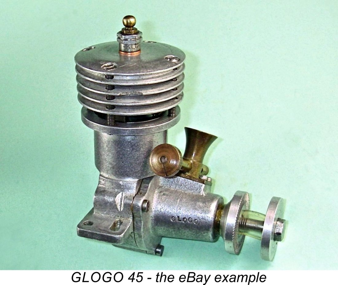 The eBay example was advertised by the seller as a .45 cuin. engine, although this was an estimate only since no precise measurements had been taken to confirm this displacement. The engine was stated to be in very good condition, with strong compression. As we’ll see, this description proved to be somewhat less than completely accurate …………
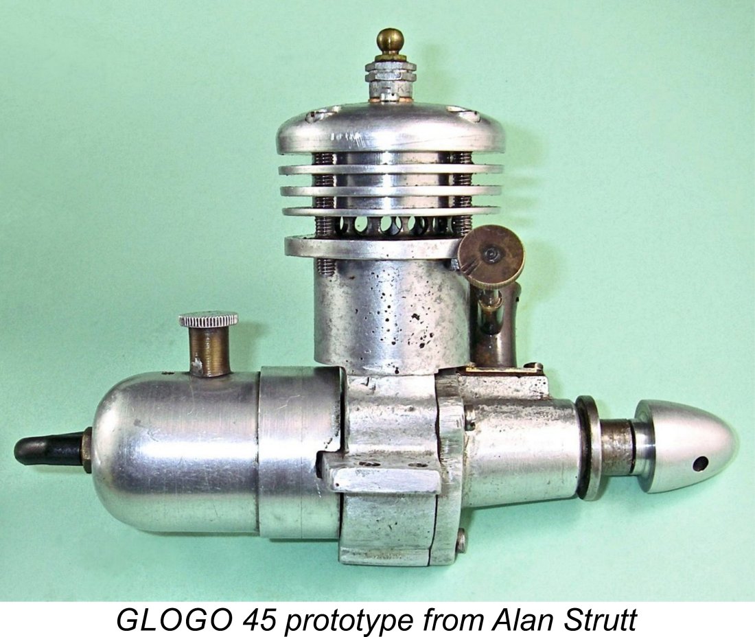
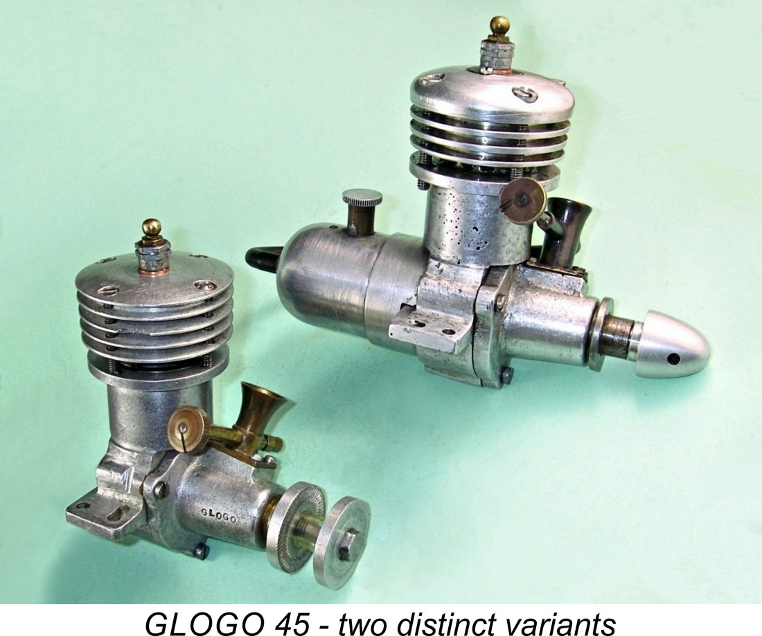 The direct family relationship between the self-identified GLOGO and Alan’s unidentified unit is immediately and unarguably obvious. Both units are clearly based upon the same set of main sand-castings and follow the same general design layout. However, a number of quite significant differences are readily apparent.
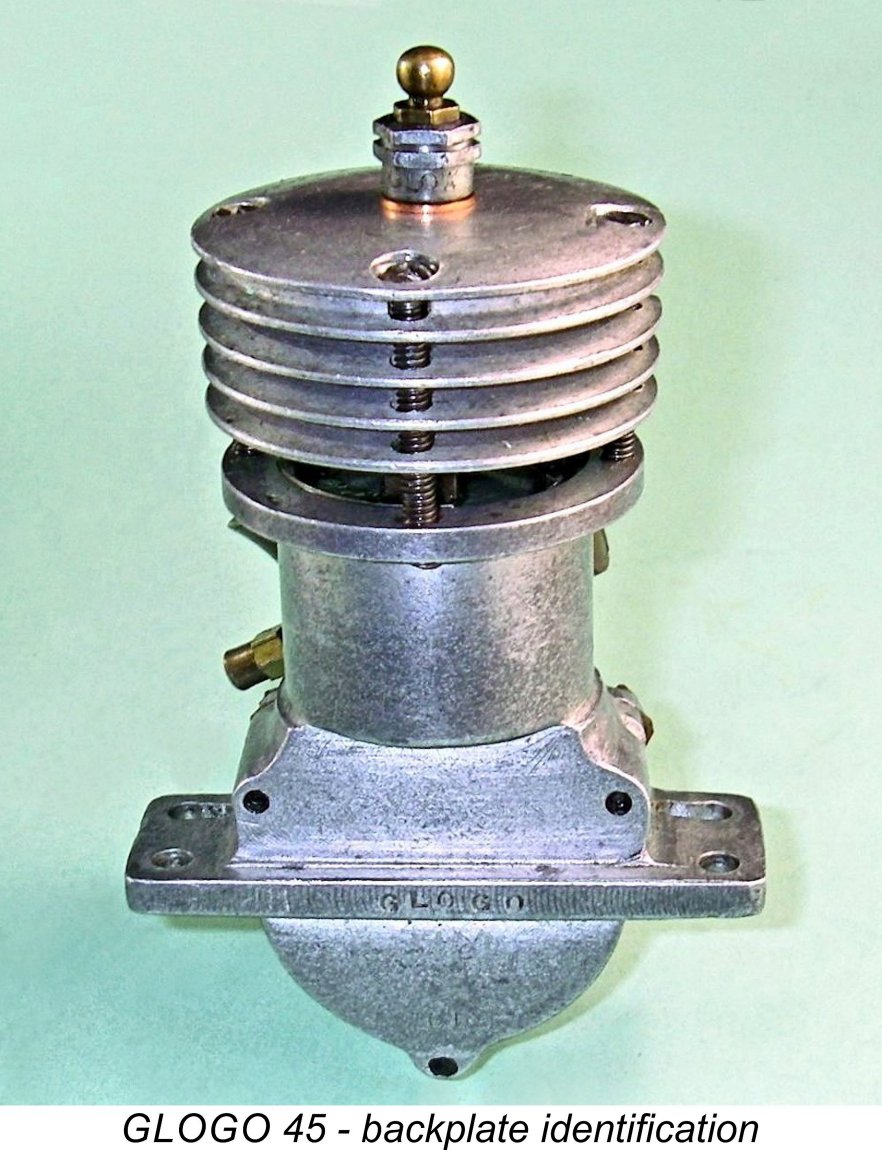
 Bore and stroke of Alan’s engine were found by direct measurement to be 0.872 in. (22.15 mm) and 0.745 in. (18.92 mm) respectively for a calculated displacement of 7.29 cc (0.445 cuin.). The nominal design bore and stroke dimensions were evidently
 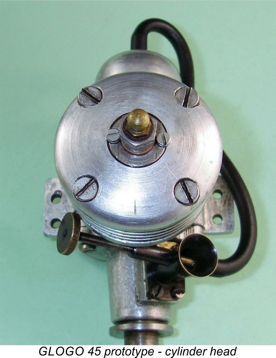 casting machine work, with some manual fettling having been undertaken to achieve final con-rod clearances. Whoever made these engines was a first-class machinist having access to a wide range of good equipment which he knew how to use.
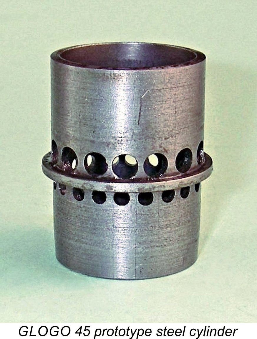 the crankcase by a narrow flange between the exhaust and transfer ports. This flange sits on a slightly recessed shelf which serves to centre the cylinder axially in the crankcase installation bore. The bypass consists of the narrow annular space between the inner wall of the crankcase installation bore and the outer wall of the lower cylinder. Somewhat unusually for what appears at first sight to be a home-constructed engine, the steel cylinder is hardened.
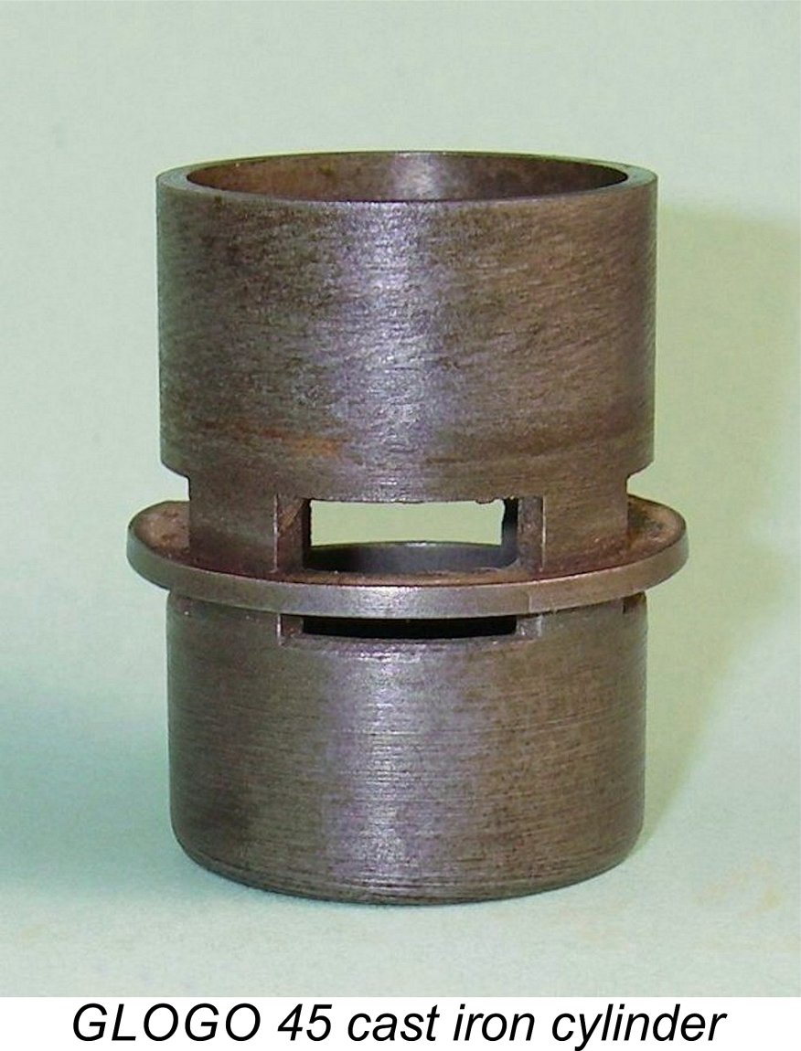 By contrast, the eBay engine uses a cast iron cylinder, a somewhat problematic choice of material for a cylinder of this design. This cylinder features generously-dimensioned rectangular ports. The fact that the exhaust and transfer ports are aligned one above the other leaves only a rather flimsy unsupported length of flange separating them. This design shortcoming had led to the fracture of the unsupported location flange in the vicinity of one of the ports, leaving the crankcase open to the atmosphere and thus rendering the engine inoperable until a replacement cylinder could be made. I communicated with the eBay seller on this issue and was successful in negotiating an appropriate price adjustment. The seller’s honesty was very much appreciated!
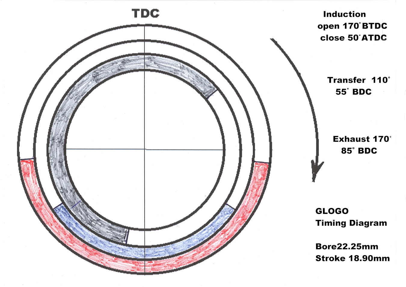
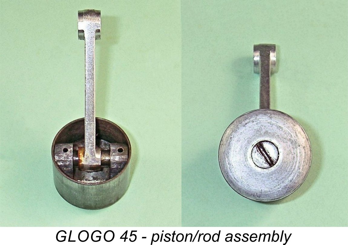
 In both engines, the rod drives a one-piece steel crankshaft having a main journal diameter of 0.375 in. and a generous crankpin diameter of 0.250 in. set in a heavily counterbalanced crankweb. Both are standard British dimensions.
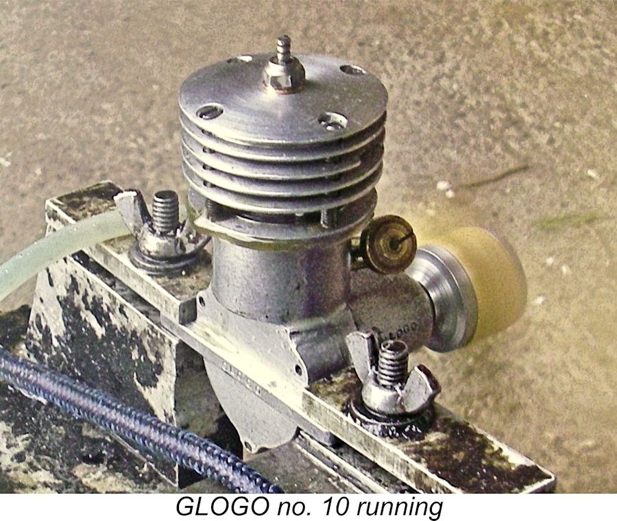
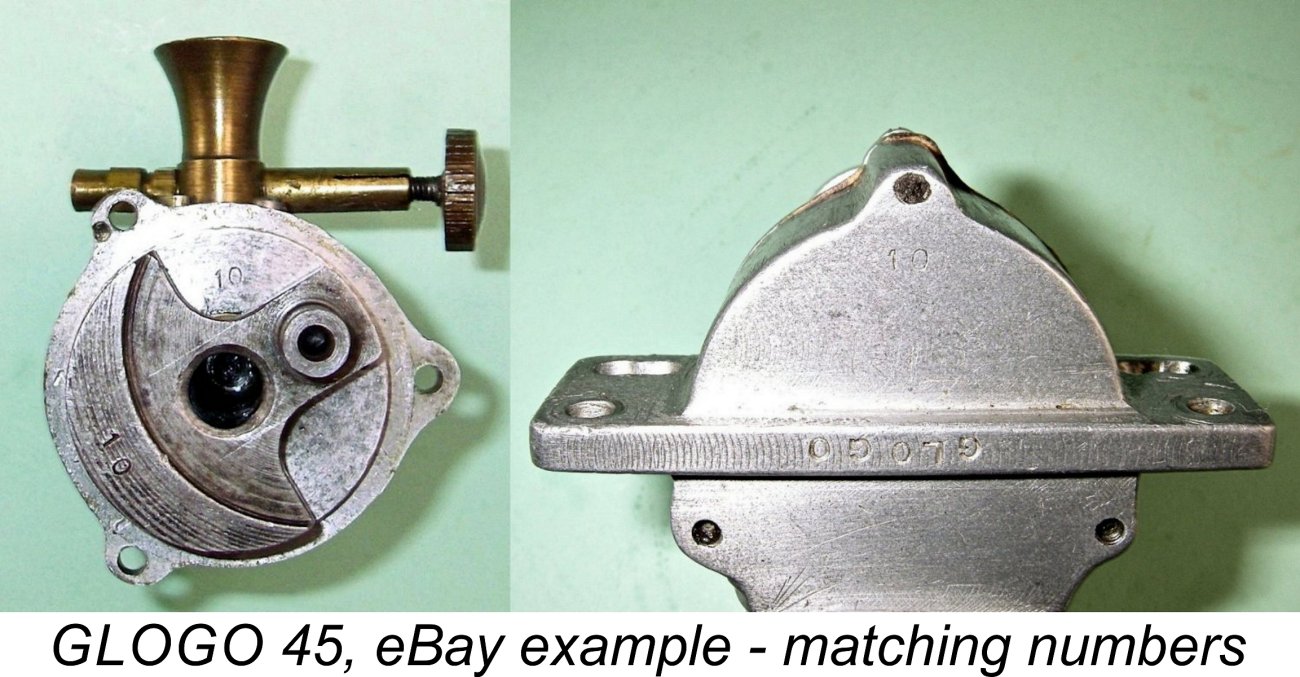 A fascinating observation in relation to the eBay example is the fact that the main crankcase casting, the crankweb and the front housing all bear a matching stamped-on number, in this case the number 10. This implies very strongly that they were custom-fitted to each other. Could the fact that the number 10 appears on all three components imply that at least that many examples of the GLOGO were made …..?!? There’s no way of knowing. Regardless, the number 10 appears to be the serial number of the eBay example.
 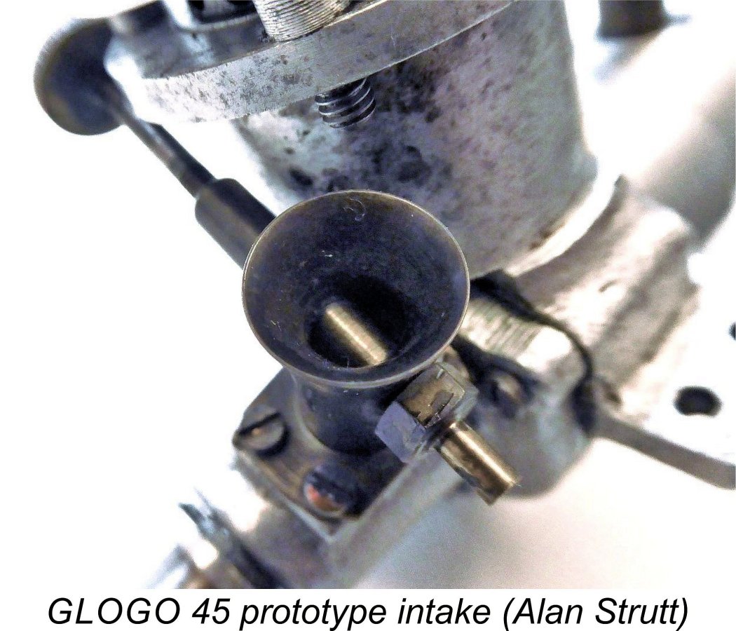 At first sight, this appears to be a somewhat awkward arrangement in terms of mounting flexibility. However, a little thought soon allays any concerns. When the engine is mounted in an upright configuration, the needle valve control is very conveniently placed for easy access on the right hand side (looking forward in the direction of flight). But what about sidewinder mounting as in many control-line applications? Actually, that’s not too bad either - re-installing the components with the needle on the left orients the control at a 30 degree angle to the left at the top of the model rather than the more usual vertical alignment - still readily accessible!
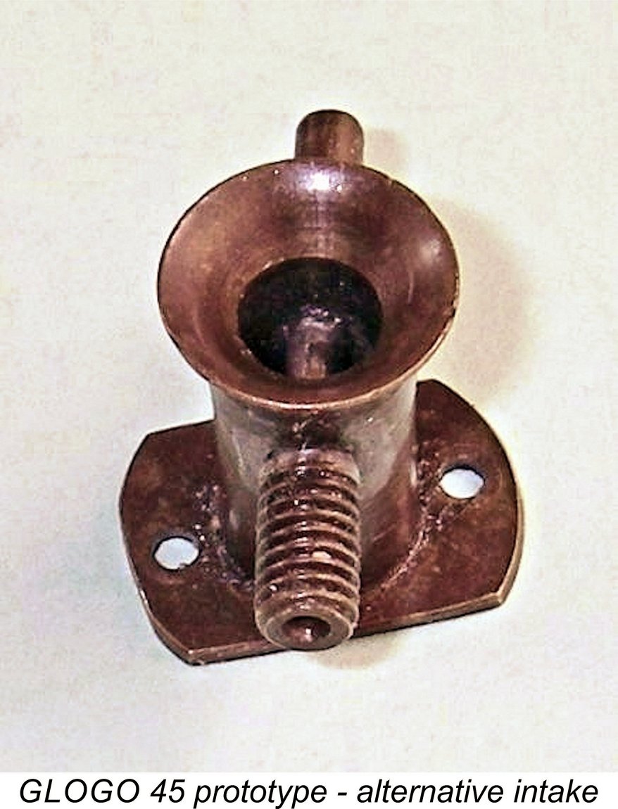
 Following our initial exchange of information, Alan very kindly agreed to sell me his example of this very obscure engine. We both saw value in bringing these two examples together for comparative study. For my part, it’s my intention to keep them together in the future - when the time comes for me to pass them on, I will only do so as a pair.
 Never mind - onwards and upwards!! Engine no. 10 started and ran in a more or less identical manner to its prototype predecessor. It needed a prime for starting, but was a consistent one- or two-flick starter if this was done. The needle valve functioned perfectly, with no requirement to deploy the remote needle valve. Once again, vibration levels seemed to remain well within acceptable limits.
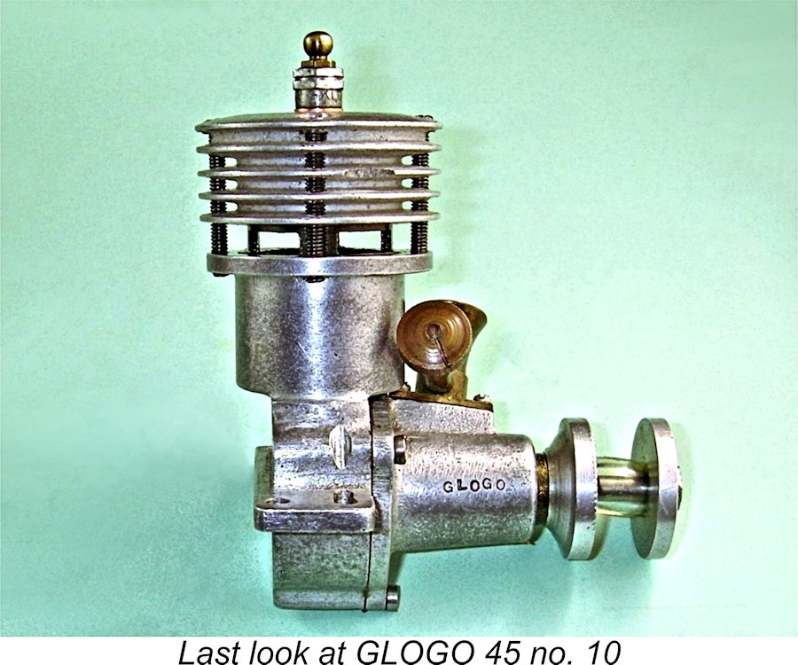 The extreme rarity of these units appears to confirm that whatever and wherever its source, the GLOGO never reached even small-scale commercial production. Even so, it seems not unlikely that a short series was in fact constructed. If we accept the seeming probability that the engines were developed and constructed by a skilled model engineering hobbyist as opposed to a commercial workshop, he may well have constructed a number of examples for the use of himself and his friends. Accordingly, it’s entirely possible that other examples exist, although the evident rarity of the engine is such that the number cannot be large. The number 10 which appears in several locations on the presumably later eBay example is consistent with this possibility.
 | |