
|
|
Another Forgotten British Pioneer – the Jopson Engine
In a separate article to be found on this website, I’ve summarized the story of perhaps Britain’s earliest successful exponent of power aeromodelling, the English automotive engineer and keen model enthusiast David Stanger (b. 1871). In the present article, I’ll set out what is known about the work of a contemporary of Stanger, W. G. Jopson. The available information about the activities of this individual is somewhat scanty, but enough is available to at least present the main outline. Before proceeding with the telling of the Jopson story, I must pay tribute to the efforts of my valued Aussie friend and colleague Gordon Beeby, whose indefatigable efforts to search out relevant references did much to inform this effort. Without Gordon's assistance, I would never have tackled this challenging subject. Many thanks, my friend! Background
That first engine was an air-cooled four-stroke four-cylinder "V" type. Each of its four cylinders had a 1.25 in. bore, which combined with a stroke of 1.5 in. to yield a total displacement of 7.36 cuin. (120.6 cc). The engine weighed 5½ lbs. (88 oz.) complete with gravity-fed carburettor and petrol tank – actually a commendably low weight for an engine of this displacement and complexity. Stanger estimated the power output as 1¼ horsepower at 1,300 RPM, although subsequent testing showed this to have been a somewhat optimistic estimate. Regardless, the engine reportedly turned a 29 in. diameter prop having a pitch of 36 in. at around 1,300 RPM. Plenty of low-end torque on tap! Stanger’s achievement in designing and building an engine of such relatively small dimensions by the standards of the day which operated with a high degree of efficiency by those same standards can only reflect positively both on his techical capabilities and on his deep appreciation of I/C engine principles and design at a time when such knowledge was confined mainly to the few who had attempted to build full-sized engines.
The V-4’s evident success soon led Stanger to construct a second variant. This was a V-twin weighing 2.6 lbs.(42 oz), less than half the weight of his first design. This should come as no surprise, as it was in effect one-half of the V-4, having a displacement of 60 cc. Stanger used this engine in 1914 to establish the first-ever officially-recognized British duration record for a powered model aircraft – a stunning 51 seconds OOS (the aircraft was subsequently recovered from its eventual landing spot outside the flying area!). His model on this occasion was a canard biplane having a wingspan of 7 feet (84 in.). With Stanger’s new far lighter V-twin aboard, the aircraft weighed in at 10¾ lbs. ready to fly. The V-twin engine reportedly drove the 22 in. dia. x 18 in. pitch prop at 2,000 RPM. But this is to get ahead of our story! Time now to leave David Stanger basking in the afterglow of his successes while facing the onset of WW1 and return to our main subject – the almost parallel efforts of W. G. Jopson. The Jopson Engine - Background Authoritative personal information on W. G. Jopson is in short supply. However, there appears to me to be a strong circumstantial possibility that he was the William George Jopson who was born in Birmingham on September 20th, 1882. Gordon Beeby did a Patent seach which turned up a remarkable number of both British and US Patents under the name of William G. Jopson. Among these was a 1905 British Patent relating to machine guarding which listed William George Jopson as a resident of Nottingham and a "tool draftsman" by profession. It is known that the W. G. Jopson with whom we are concerned was a member of the pioneering Manchester Aero Club, evidently living in the vicinity of that city as of 1910. A move from Nottingham to Manchester between 1905 and 1910 is by no means inconceivable, making it seem entirely possible (albeit unproven) that William George Jopson is indeed our man. He appears to have been associated in some way with an engineering firm called Cook & Co., who operated from the Standard Works in Altrincham, Cheshire, some 8 miles to the south-west of Manchester City Centre. This company was owned by John William Cook of Manchester, who gave his occupation as "machinist" in a 1910 patent application (see below). It's possible and perhaps even likely that Jopson actually worked for Cook & Co.in his professional capacity as a tool draftsman.
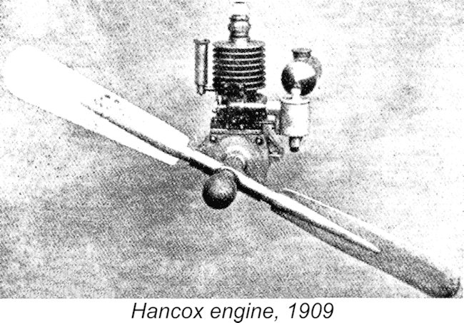
An important source of information on this pioneering era is to be found in the form of a two-part article by Alan Denham entitled “Model Engine Archaeology” which appeared in the October and November 1996 issues of “Model Engine World” (MEW) magazine. This article tells us that credit for the earliest recorded British commercial model aero engine appears to be due to Charles Hancox, who began to offer specially lightened aero versions of his 47 cc two-stroke boat engine in 1909.
The selling price of this unit as originally released was £4 4s 0d (£4.20) complete with fuel tank, a spray-type carburettor and a matching airscrew. It was also available with a flywheel in place of an airscrew for boat applications, the price being £3 15s 0d (£3.75). It was clearly equipped for trembler coil ignition, since a matching “special light aero trembler coil, for use with these engines” was available for 10s 6d (£0.53). Since this coil weighed no less than 13 ounces (!!), the term “light” might appear to us to be somewhat inappropriately applied! To complete the package, miniature spark plugs were offered at 2s 3d (£0.11). Gamages claimed an output of 1 horsepower at unspecified RPM for this engine. A watercooled version of essentially the same engine for marine or stationary use was also available. However, Jopson was evidently little influenced by the appearance of the Hancox and Gamages two-stroke engines – he clearly thought that he could do better! He was doubtless encouraged by the well-publicized aerial success of Stanger’s four-stroke efforts beginning in 1908. During 1910 he finalized the design of his own four-stroke opposed twin-cylinder model aero engine and arranged for its manufacture by Cook & Co., who displayed examples of this and another engine of unknown type at a September 24th, 1910 competition organized by the Manchester Aero Club, as reported in the October 5th, 1910 issue of "AERO" magazine. It seems likely that Jopson was actually an employee of this firm.
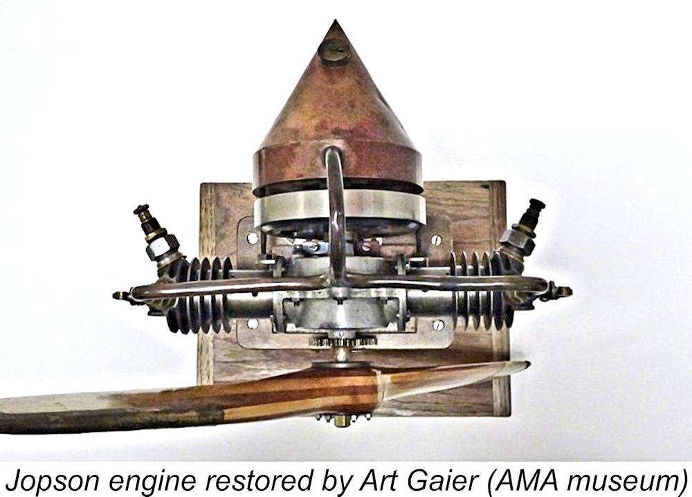
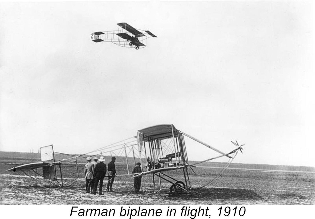
A number of earlier references to be found in both "FLIGHT" and "AERO" magazines make it clear that Brent and Jopson were fellow members of the Manchester Aero Club. Indeed, it's possible that they were both Cook & Co. employees. Brent was reported to have built a large petrol engine-powered model which may well have been fitted with a Jopson motor. Brent's article (right) claimed that the engine had undergone several months of testing, making multiple runs every week and sometimes running on successive nights. A run was said to typically last about twenty minutes, but one of the engines was said to have made a continuous run of one hour. This relatively arduous testing program had clearly shown the engine to be quite a reliable performer. Nothing was said about the engine being used successfully to fly a model despite the fact that Brent had previously been credited with the construction of a model which logic suggests may well have been fitted with a Jopson motor. However, Jopson himself appears to have been convinced of the engine’s readiness for such an assignment, because Brent's article stated that he was then in the process of building a quarter-scale model of a Farman biplane Further details have been revealed far more recently by the successful efforts of Art Gaier to restore an example of the Jopson engine. As of 2026, Art’s superb restoration was on display in the AMA’s National Model Aviation Museum in Muncie, Indiana, USA. I have no information regarding whether or not this outstanding restoration was ever run. See below for more details. George Brent included the statement that “The makers of these motors are Messrs. Cook and Co., Standard Works, Altrincham, Cheshire”. This wording appears to confirm that some level of series production was achieved. Indeed, the Jopson engine is often referred to as the “Cook engine” in recognition of its actual manufacturer - Alan Denham certainly referred to it as such in his MEW article. However, the number manufactured must have been very small – only two examples of this engine are definitely known to survive today, 115 years later. The Jopson Engine - Description
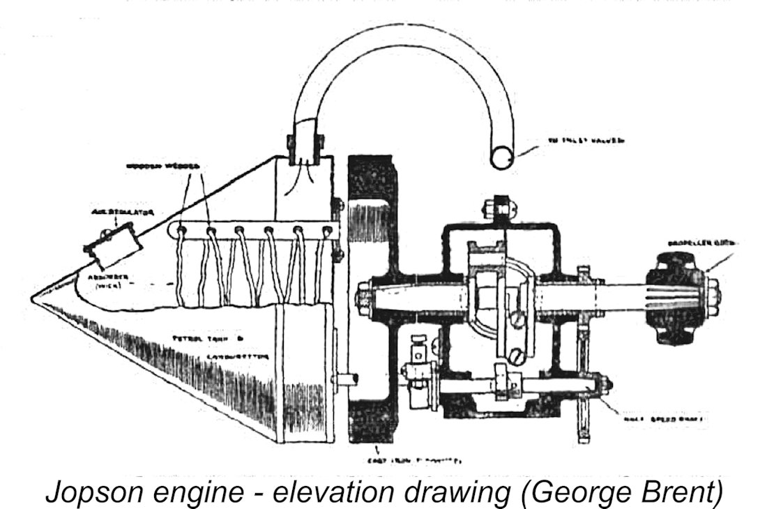
In large part this appears to have been due to the fact that the Jopson engine featured a heavy flywheel (clearly seen in the accompanying sectional drawing from the Brent article), while Stanger very sensibly relied on the very heavy airscrew to serve the flywheel function. Presumably the typical aero user of Jopson’s engine would dispense with the flywheel, doubtless shedding a considerable amount of weight in the process.
The engine’s breathing arrangements were a little unusual by later standards. The inlet valve was atmospherically controlled and was oriented at a 50-degree angle like the similarly-angled spark plug. The exhaust valve was mechanically actuated by the underslung camshaft and was positioned vertically at the centre of the head. The exhaust appears to have been a simple hole through the side of the exhaust valve extrusion opposite the spark plug.
The effect of this would be to minimize the internal gas pressure against which the camshaft would have to open the exhaust valve, which explains why Jopson could get away with using such lightly-constructed exhaust valve actuating gear. However, the holes would also be open near the end of the inlet stroke, thus serving to supplement the function of the atmospheric inlet valve in a manner rather analogous to sub-piston induction in a two-stroke. Quite a logical feature! These holes are clearly visible in the photo at the right.
A less than praiseworthy design feature arose from the designer’s wish to align the two cylinders on a common axis. Since the two crankshaft throws were necessarily offset from one another, this meant that the conrod small ends had to be located well off centre within the pistons. The accompanying component view confirms that the gudgeon (wrist) pins were of rather small diameter, which would not have helped in this situation. The crankcase was cast from aluminium alloy in two segments. It was vertically split along the vertical transverse centre line. Each half incorporated a bronze bushing to support the opposite ends of the two-throw crankshaft, which was machined in one piece from a 2 in. dia. steel bar. The rear portion of the shaft carried the flywheel, while the other end incorporated both the camshaft drive gear and the prop mounting hardware.
In his previously-cited MEW article, Alan Denham clarified this term - the commutator was the early forerunner of the later cam-operated points timer. The typical commutator was a non-conducting vulcanized fibre disc which incorporated a brass conducting segment. The unit was equipped with a spring-loaded wiper arm which bore against the surface of the disc, closing and reopening the primary circuit at the appropriate times by making periodic contact with the conducting segment of the disc. This system was very much akin to the “wipe-swipe” commutator timers used quite effectively on a number of the early post-WW2 slag engines, of which much more elsewhere. Such devices were frequently employed with the early trembler coil ignition system then in fairly common use. However, it’s possible that it was used on the Jopson engine as a simple make-and-break device forming part of a conventional coil-and-condenser ignition circuit. George Brent commented that “very light coils are now obtainable at a reasonable price”. These “very light coils” were presumably not of the relatively heavy trembler variety.
The spark plugs used with this engine were characterized by George Brent as being especially light and simple, reportedly giving very little trouble. Such small plugs were available commercially from Gamages and perhaps elsewhere, but it’s equally possible that Jopson made them himself. David Stanger certainly had to make the plugs that he used in his engines – it’s quite likely that Jopson did the same.
This was one of the earliest approaches to the problem of carburetion in an internal combustion engine. Amazingly enough, a properly-designed system of this kind can work surprisingly well, especially in a one-speed application like an unthrottled model aero engine - it has even been applied successfully to modern generator engines on an experimental basis. Adjustment of the system for best operation is achieved by varying the amount of induced air rather than controlling the amount of fuel entering the system. A degree of mixture adjustment is also possible by varying the thickness or number of wicks.
The tank was secured to the rest of the engine by a pair of studs passing forward beneath the flywheel on either side as well as by the metal induction tubing attached to the top of the tank. It should be clear from the foregoing description that the engine as supplied could only be operated with its own tank installed, since that tank also incorporated the carburettor. However, a spraybar type of carburettor could have been installed on the intake pipe in place of the conical tank, allowing the use of a separate tank. There’s a bit of a mystery surrounding the engine’s lubrication arrangements. The exposed valve gear and camshaft drive gears would obviously have to be hand-lubricated between runs. It would be logical to assume that the internal working components would be splash-lubricated from an oil bath inside the crankcase. However, the fact that the pushrod outlet ducts are located at the bottom of the case leaves us wondering how those ducts were sealed, as they would have to be for the engine to retain its internal oil bath. Only direct examination of an actual example could settle this point. Performance
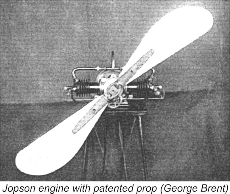
Jopson designed a series of airscrews especially for use with this motor. His prop design was sufficiently original that his presumed employer John William Cook was able to patent it (Patent no. 7783, applied for March 31st, 1910, accepted January 26th, 1911). The propellers were evidently put into production at some level in concert with the limited manufacture of the Jopson engines themselves. Cook & Co. also manufactured rubber-tyred spoked wheels which one reviewer described as being “exquisitely made”, as well as various other metal accessories. The Jopson propellers were made entirely of aluminium alloy. They were designed to offer variable pitch, with the blades being graduated so that any desired pitch, within certain limits, could be arranged. They were made available in four sizes, namely 15, 20, 25 and 30 ins. diameter.
As an example, the diagram showed that an engine running at 1,540 RPM on a 30 in. dia. airscrew with a pitch of 15 in. would develop a thrust of 9½ pounds. Fair enough if true, but of course the key question was whether or not the engine would actually turn a 30x15 airscrew at that speed! The diagram was silent on that point. Given the fact that David Stanger’s contemporary slightly larger-displacement V-2 could only manage 2,000 RPM on a 22x18 prop, it seems doubtful to me that Jopson’s creation could have turned a 30x15 prop at 1,540 RPM. A 25 in. dia. airscrew would appear to be somewhat nearer the mark. Nevertheless, there are good grounds for believing that Jopson’s engine was seen by some as a useable model powerplant. Several photographs of a model powered by what was clearly a Jopson engine appeared in the February 10th, 1912 issue of "FLIGHT". The builder of this model was identified as Cook & Co.'s London-area distributor T. W. K. Clarke. The same photographs appeared in the book “Model Aeroplaning: Its Practice and Principles” by Valentine Edward Johnson in 1922. The photographs Despite all of the information provided on Clarke’s model (including the closing statement “Note the neatness and compactness of the (power)plant, also its high position and the large size of the propeller.”), what these references notably do not provide are details about any flights made with the model. However, T. W. K. Clarke sold both model and full-scale airplanes, also being an active aeromodeller and a frequent contributor to “FLIGHT” magazine. This being the case, it seems almost certain that he had tested the engine and found it to be an acceptable performer, otherwise why spend the time and effort constructing a model for it? Since he undoubtedly did so, there’s every reason to assume that he must at least have tried to get the model off the ground with the engine running – it seems doubtful that he would publicize a model which he knew to be a non-performer. That said, if any record of such attempts exists, it has yet to be located. For his part, William George Jopson (assuming that we've identified him correctly) moved to the USA at some point shortly prior to the outbreak of WW1 and applied his inventive talents to other fields. He seems to have established his own US company called the Jopson Manufacturing Company, also taking out many US Patents under the name of William G. Jopson between 1916 and the early 1940's. A number of the earlier US Patents were assigned to the Jopson Manufacturing Company, whose business seems to have centred upon the production of yarn processing equipment, industrial labels and automatic labelling machines. These early US patents have Jopson recorded as a "subject of the King of Great Britain", with various US addresses. Jopson seems to have wound up his own business during the 1920's, since from the mid 1920's to the early 1940's his Patents were assigned to the C. A. Reed Company of Pennsylvania, for whom he was presumably now working. These Patents covered paper manufactured products and machinery (e.g., paper ribbons, flowers, napkins, cups). Jopson's personal addresses were also located in Pennsylvania, while the notation "subject of the King of Great Britain" no longer appeared on the record - evidently Jopson had become a US citizen. He eventually died in August 1970 in Lycoming County, Pennsylvania, USA at the age of 88 years. The Art Gaier Restoration
It turned out that between the two of them they had a full set of parts for one complete engine, thus having details and dimensions of all of the engine’s components. This being the case, they were able to provide measurements, photographs and drawings of missing parts to each other. The information provided in the previously-cited 1912 and 1916 publications by George Brent and G. A. Cavanagh respectively was also extremely helpful. I have no information regarding the outcome of the presumed English restoration of one of these engines. However, upon completion of his restoration, Art Gaier very generously made his restored example available to the AMA for display in their museum in Muncie, Indiana on a long-term loan basis. It is this example which appears in the majority of the accompanying illustrations. Art’s restoration is a truly superb piece of work which looks as if it’s all ready to run! It serves as a fitting tribute to the efforts of one of power aeromodelling’s true pioneers! ____________________ Article © Adrian C. Duncan, Coquitlam, British Columbia, Canada First published March 2026 Revised May 2026
|
 Regular readers of these pages will recall that some time ago I began a concerted effort to document the pioneering era of British power aeromodelling. By this I don’t mean merely the early years of commercial model aero engine manufacture in Britain, which really began in the early 1930’s, but the true pioneering era of the early 20
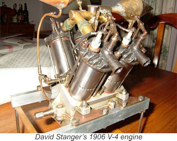 Although he may not have been the first British individual to have a go at making a model I/C aero engine, David Stanger was almost certainly the first such person to make a successful I/C engine for this purpose - indeed, he was among the first anywhere. His first powerplant was designed in 1905 and built by the 35-year-old Stanger in 1906. Remarkably, he used a lathe and measuring equipment of his own construction in making this motor.
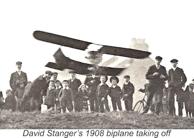 When considering Stanger’s first powerplant, it’s important for context to relate the date of its design to other aeronautical events of the period. That engine was designed only eighteen months after the Wright brothers achieved the world’s first controlled flight by a manned engine-powered aircraft, and four years before Louis Bleriot flew across the Channel. It is an often under-appreciated fact that the development of powered model aircraft lagged only a few years behind the emergence of full-sized powered aviation. Today’s power modellers are participating in a hobby that is almost as old as aviation itself!
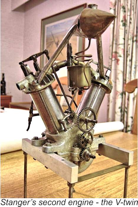
 Asuming that we have identified the correct W. G. Jopson (which is far from a common name), he would have been 28 years of age as of 1910. Jopson clearly shared David Stanger’s enthusiasm for powered model aircraft. However, the extreme scarcity of suitable commercially-available model I/C engines at the time steered him towards designing and producing his own engine, just as it had done for Stanger.
 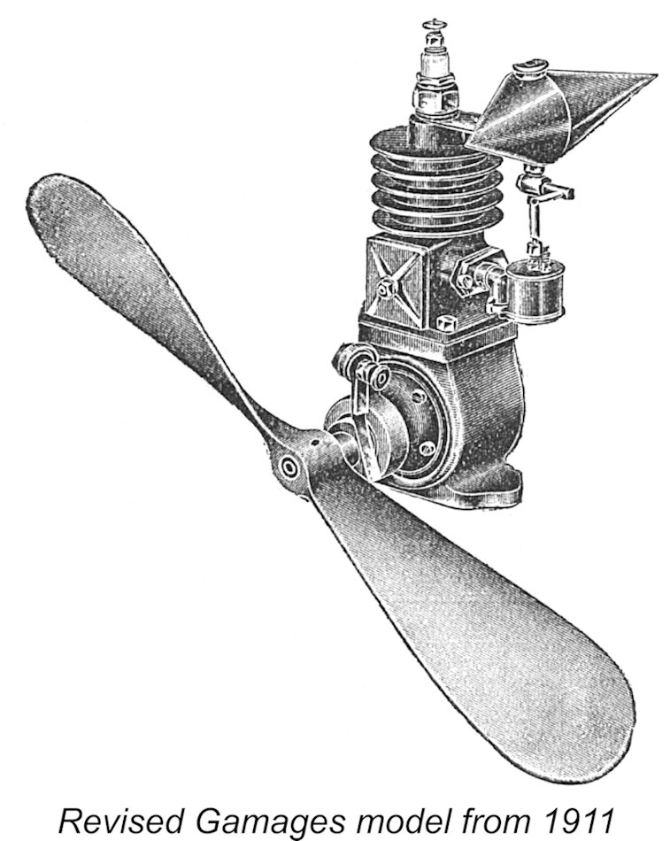 The Hancox design was taken up in 1910 by the famous Gamages department store in London. It was offered by Gamages throughout 1910 but was replaced in the following year by a significantly revised model. This was a single-cylinder two-stroke having bore and stroke dimensions of 1¾ in. and 2 in. respectively for a displacement of 78.8 cc. It weighed 6¾ lbs. (108 oz.) and developed a claimed 1 horsepower. Although there's no direct evidence, it's possible that this revised engine was designed by the well-known model engineer F. N. Sharp, who certainly designed the later Gamages model of 1914, which had a similar but reduced-scale design and weighed less than 2 lbs.
 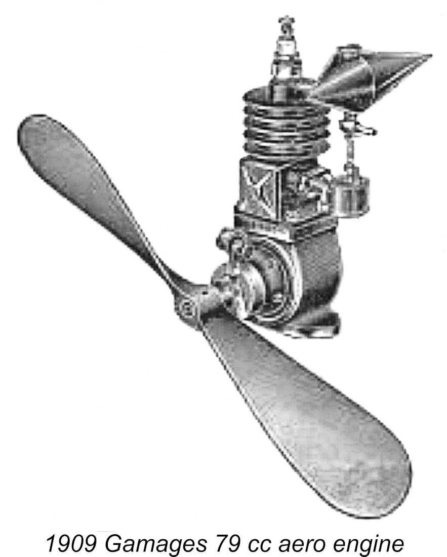 By 1911, the Jopson engine had been put into some level of commercial production. Morover, the well-known firm of T. W. K. Clarke of Kingston-upon-Thames, Surrey had become the distributors of the engines produced by Cook & Co. An example of the opposed twin Jopson engine was displayed by Clark at the third International Aero Exhibition held at Olympia, London during March - April of 1911, along with a single cylinder unit which may or may not have been another product of Cook & Co. - possibly the second unit displayed by that company in September 1910 as noted earlier.
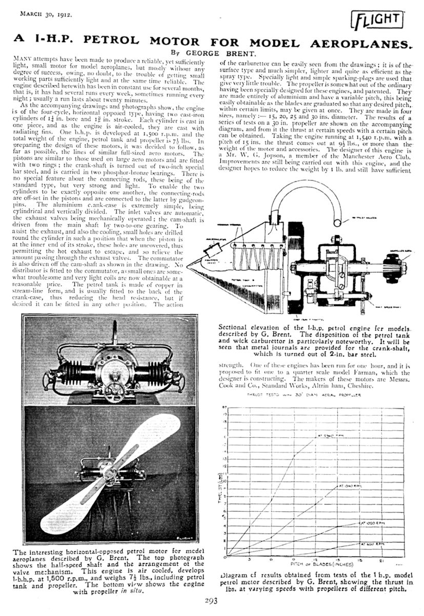
 The engine designed by W. G. Jopson and built by Cook & Co. owed little to the earlier efforts by David Stanger. It was an opposed twin-cylinder four-stroke unit, with each cylinder having a bore of 1¼ in. Combined with the stroke of 1
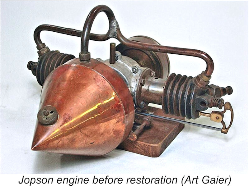 The two cylinders were iron castings, each cylinder being formed from a single casting which included the head in unit. The cylinders were thus blind-bored. Unlike the Stanger engines, they were equipped with cooling fins. Although I can’t confirm this from direct inspection, it appears that the inlet valve seats were formed in separate screw-in components – it’s hard to see how the seats for those valves could have been formed directly in the blind-bore head.
 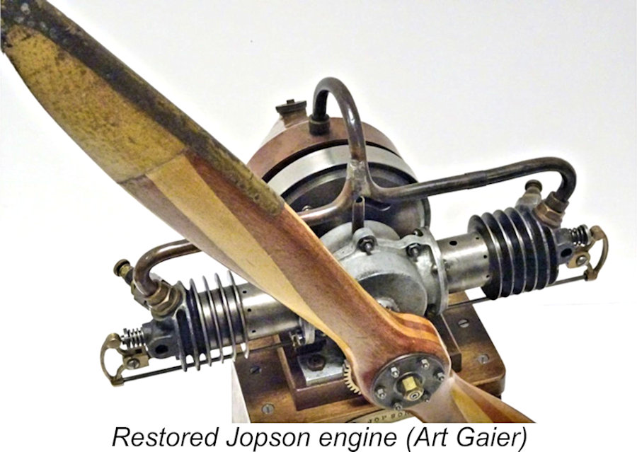 The operational function of both valves was supplemented by a ring of small holes radially spaced around the lower portion of the bore so that they opened when the piston neared bottom dead centre – in effect, late-opening two-stroke exhausts. The stated purpose of these holes was to assist the exhaust valve by offering an initial pathway for the exhaust gas just prior to the start of the exhaust stroke – a kind of two-stroke/four-stroke hybrid system. David Stanger had included a similar feature in his V-4 powerplant of 1906.
 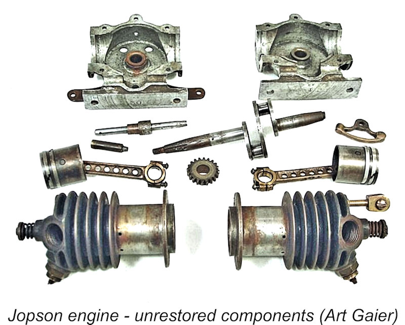 The pistons appear to have been machined from castings of some indeterminate material and fitted with two piston rings apiece. They drove the crankshaft through a pair of phosphor-bronze conrods which were extensively drilled for lightness. Since the two-throw steel crankshaft was made in one piece, these rods were necessarily fitted with removable end-caps on the big end bearings.
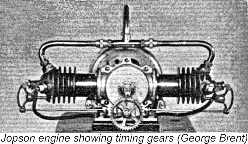 The camshaft was positioned directly below the crankshaft, being driven at half engine speed through exposed spur gearing. It passed through the lower crankcase, engaging with the exhaust valve pushrods through a separate cam which was somehow secured to the camshaft in the appropriate radial orientation. At its emergent rear end, it also actuated the ignition timer, which was characterized in George Brent’s article as a “commutator”.
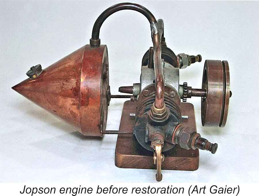 Since the “commutator” rotated at half engine speed along with the camshaft, we might suspect that the cylinders were simultaneous-firing, requiring that the timing device only had to deliver simultaneous sparks to the two cylinders every second crankshaft revolution. However, this notion is refuted by the fact that the exhaust valves were actuated by the same cam, which could only lift one of them every crankshaft revolution, forcing the cylinders to be alternate-firing. It’s possible and even likely that the timer delivered sparks to both cylinders on each revolution – while one cylinder was ready to fire, the other was completing the exhaust stroke, meaning that the spark would have no effect on operation since there was no fuel mixture to ignite.
 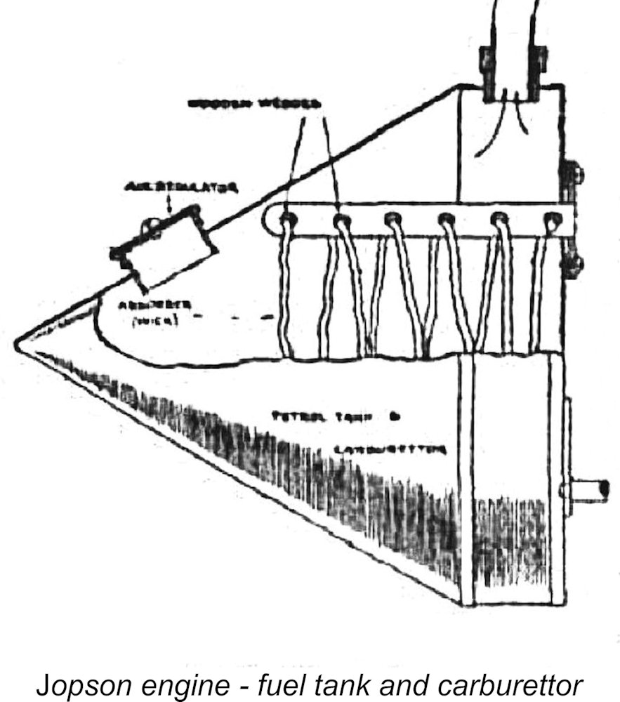 The fuel supply arrangements for this engine will seem strange indeed to modern readers. The engine used the very early
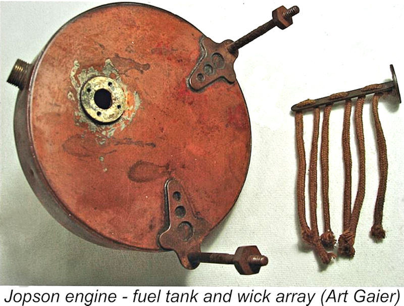
 We already saw that examples of this engine had undergone a lengthy series of successful operating tests. On the basis of these tests, the designer claimed that his engine would develop 1.0 horsepower @ 1,500 RPM. I have to say that this figure seems highly suspect to me. It would take a massive amount of torque from the engine's 55.3 cc to develop that kind of power at the cited speed - I simply can’t see this engine performing at that level. Lacking an opportunity to test an actual example, that’s about all that I can say on this subject!
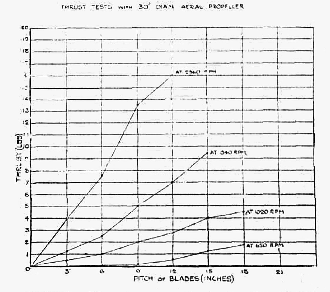 The results of a series of tests on a 30 in. propeller set at various pitches were shown on the accompanying diagram which appeared as one of the illustrations with George Brent’s 1912 article. This diagram showed the thrust developed at certain speeds with a given pitch
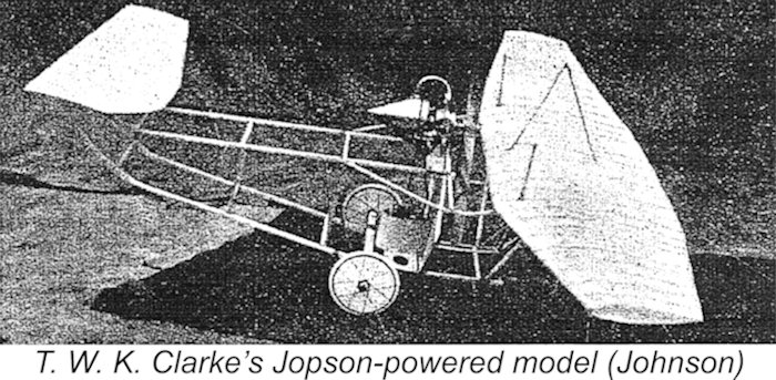
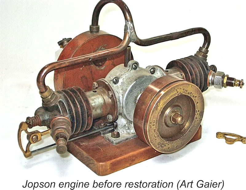 Many decades after its original manufacture, an incomplete example of the Jopson engine somehow came into the possession of Art Gaier of the USA. The engine couldn’t have fallen into better hands, since Art was an engineer and a talented machinist who was extremely well qualified to undertake the restoration of such a unique piece of model engine history.
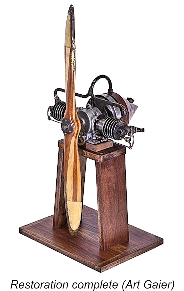 When Art Gaier first received the Jopson, it was missing a number of components and generally looked pretty old and worn. Art’s immediate difficulty was to obtain details of those missing components and their assembly. After spending a considerable amount of time searching the Internet and talking to various people, he finally made contact with the owner of another Jopson motor in England and started a conversation with him.
| |