
|
|
Servicing the A-M 35 Piston Assembly By Dave Causer
The immediate problem which confronts the prospective restorer is the enclosed gudgeon pin in the piston assembly. Because the engine is basically a bored out A-M 25, the depth of the A-M 35's piston is necessarily very similar in order to preserve the cylinder port timings. However, the A-M 35 gudgeon (wrist) pin has been increased to 3/16" diameter from the 5/32" of the 25, no doubt to cope with the increased stresses. The piston depth is only 3/8", so a 3/16" hole for the gudgeon pin wouldn't leave much material on the piston for the compression seal. It's my guess that this is why Dennis Allen went for the enclosed pin arrangement requiring composite construction of the piston. If any readers know better, I'd be happy to be corrected!
The removal tool is a length of hex stock mild steel, the dimension across the flats being greater than 11 mm, otherwise not critical, with an 8 mm hole drilled through the middle and one end turned down to 11 mm diameter for about 8.5 mm (again not critical). The 11 mm spigot is cross-drilled 5 mm (clearance for the 3/16" gudgeon pin) and then milled away to provide an open slot. The conrod is fed down the centre of the removal tool and the inside of the piston slides over the spigot on the tool, with the gudgeon pin engaging with the slot in the spigot.
When refitting the cap, it's a good idea to insert a strip of thin alloy shim around the cap before clamping tight, since this minimises the risk of damaging the newly-honed surface. The cylinder and new piston cap are lapped/honed by your favourite method - I won't elaborate here as those techniques are well covered on the "Model Engine News" (MEN) website. Take even more care when re-assembling the motor as it’s easy to distort the cylinder liner by uneven tightening of the head bolts. The liner is relatively thin, being a bored out 25, and distorts easily. In addition, make sure that the liner is orientated so that the bridges between the exhaust ports line up with the head bolts. Otherwise, it's easy to crack the base of the exhaust flange. The pdf drawing of the required tooling may be accessed through this link. The dimensions on the drawing are metric as is my lathe, but those of you who can work with both systems will recognize the Imperial equivalents. I hope that the above will prove useful and encourage restorers to replicate the original construction, even if it is bit heavier than a conventional arrangement could be made. Whilst there is work involved in making the tooling, once made it can of course be used again and it's always satisfying to make an accurate reproduction.
The first example I owned was a bit “clicky” in the rod assembly when turned over, a common feature of any of these engines that has been used. I was expecting a simple big-end re-bush, but not so!! The gudgeon pin holes in the internal alloy carrier had elongated, so a similar tool to that described above for the A-M 35 had to be made. Rather than repeat the original design error, I replaced the working piston cap with one made from cast iron. The rebuilt engine starts and runs nicely, although they're not as powerful as they look. They’re also far less common than the A-M 35. Please feel to contact me with any questions via Adrian and the website. David Causer Lincoln, England
Editor's note: The approach suggested by Dave will result in a restoration which is completely faithful to the original construction. From a conservation standpoint, that's a most praiseworthy objective, and one which I heartily endorse. My very sincere thanks to Dave for sharing this with us! However, Dave's approach does have the effect of perpetuating several of the A-M 35's major design flaws, the chief of these being the excessively heavy piston. The combined weight of the reciprocating components in the A-M 35 (piston, gudgeon pin and con-rod) is a whopping 12 gm, which is a lot for a lightweight 3.5 cc diesel having any pretentions to a reasonable performance. The fact that the crankweb is a plain disc without any attempt at counterbalancing exacerbates this problem - the engine develops a significant level of vibration, particularly as speeds go up. It also tends to pound the con-rod big end and crankpin into a problematic state quite quickly if the engine is pushed hard. I will admit to being in the camp of the Phillistines as far as my own refurbishment of well-used examples of this engine goes. If the engine was mega-rare, or in the case of cosmetically-good examples, I'd follow Dave's approach to the letter. However, as it is, I see this as a great engine to use rather than strictly as a prime collector's item. Accordingly, when rebuilding a clapped-out and "experienced" A-M 35 which has little collector value, I have always made a new one-piece cast iron piston with a conventional gudgeon pin arrangement. I mill out the interior of this component to logical limits, going for a "squashed dumbbell" internal configuration which lightens the piston significantly while at the same time preserving a reasonable length of metal for the piston bosses. This allows me to rectify another Achilles Heel of the original design - an excessively long unsupported length of gudgeon pin with extremely short bosses at each end. This promotes both excessive cyclic bending stresses in the gudgeon pin and very high loadings on the relatively short bearing lengths at the outer ends of the pin. It was probably the recognition of these factors that prompted the use of a larger-diameter gudgeon pin, as noted by Dave. I space the new piston bosses a good deal closer than in the original carrier, thus greatly reducing the unsupported length of the gudgen pin, along with far better support for the outer ends of the pin. This of course significantly reduces the bending stresses to which the pin is subjected, allowing me to use a pin having a diameter of only 4 mm (5/32 inches) as in the A-M 25. I have never experienced any problems with my modified A-M 35's from this assembly, nor does compression leakage appear to be an issue with this gudgeon pin size.
If the A-M 35 were a rare collectible in its own right, I would be firmly in Dave's camp when it comes to refurbishment. However, there are still so many of these engines around, many of them in less-than-collectible condition, that I see little harm in modifiying a few of the more "experienced" examples to extract the best performance that they have to offer. That said, I would never modify an example that remained in good "collectible" condition. Dave's on the high ground there!
It's worth mentioning in passing that another engine which uses exactly the same piston/rod assembly is the Hungarian Proton "C" 2.5 cc diesel. I recently had occasion to rebore one of these units and elected to try the approach described by Dave in the above article. Apart from the fact that (like the JB engines) the gudgeon pin carrier is of light alloy, the techniques required to make and fit the new piston were exactly the same. The restored engine starts and runs very well, being featured in my separate article on the Proton range which may be found elsewhere on this web-site. Adrian Duncan Coquitlam, BC, Canada _____________________________ Article © Dave Causer & Adrian C. Duncan, first published April 2015 |
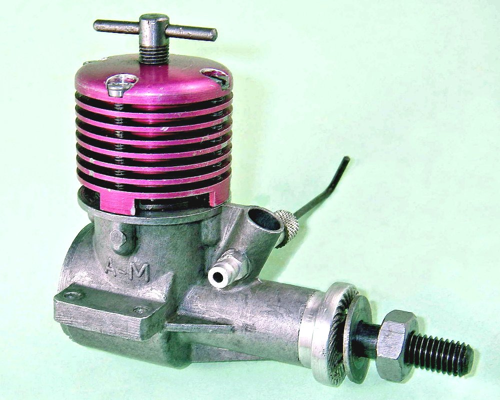 The Allen-Mercury (A-M) 35 needs little introduction to most modellers as a powerful and lightweight 3.5 cc diesel engine which is popular for medium-sized control line models and latterly for use in Slow Open Power FF events. Introduced as a “bored out” development of the A-M 25 in the mid-fifties, there are still plenty of them around and making regular appearances on eBay. Sadly, many of them have had a hard life and after over fifty years in service require refurbishment and re-bores. This is well worth doing since they're such useful motors.
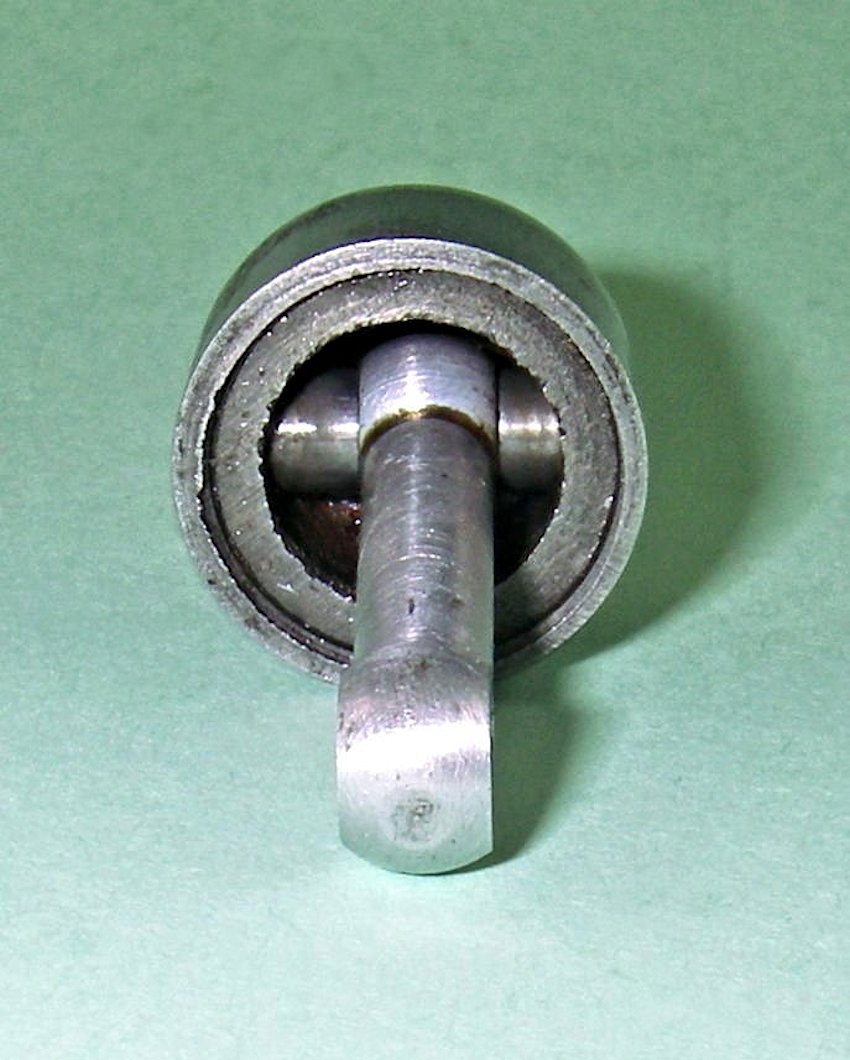 The piston comprises two separate components - an internal steel carrier ring, threaded 26 tpi on the outside and cross-drilled 3/16", which carries the gudgeon pin and conrod little end, and an internally-threaded cast iron cap which screws over the carrier, trapping the gudgeon pin and presenting a nice
 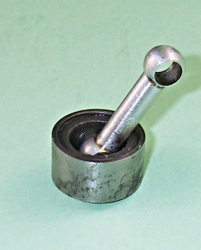 smooth unbroken working surface to the cylinder, as shown in the attached photos. The problem is how to dissassemble the thing! The attached photos and associated drawing show how I've successfully approached the problem.
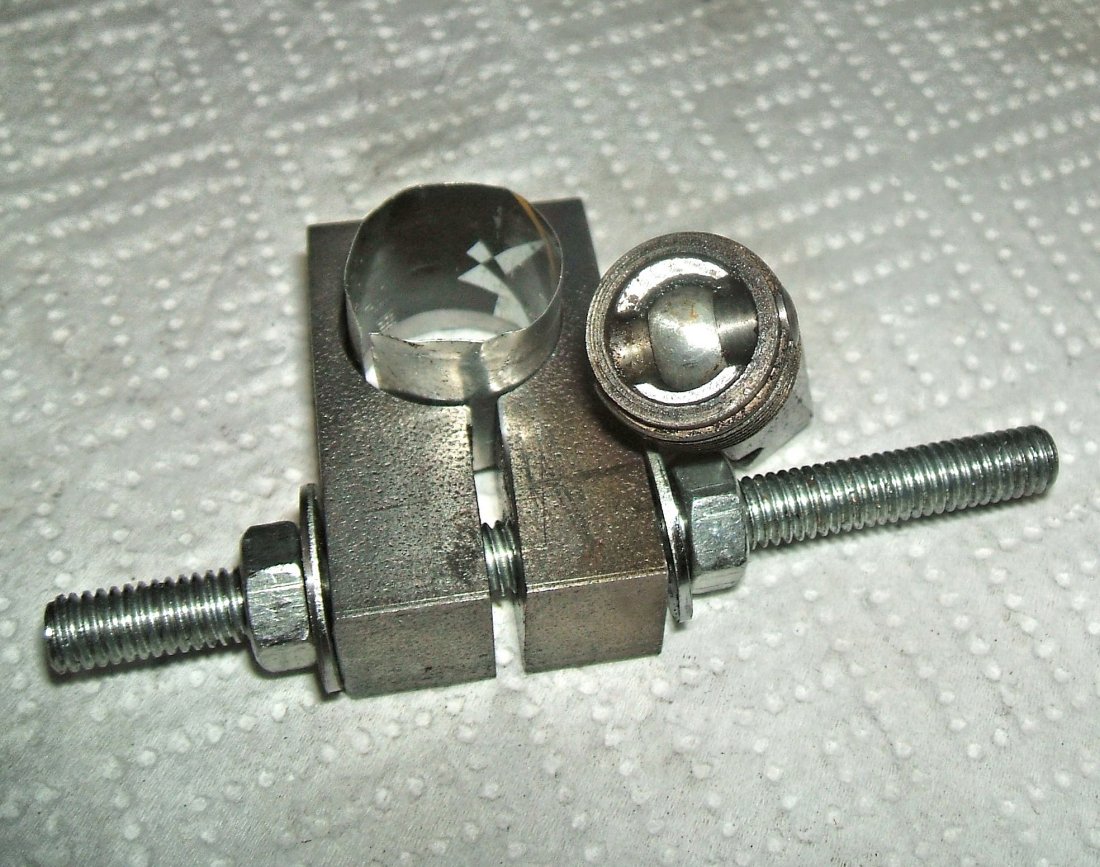 The other required tool is a special clamp for gripping the outer cap without distorting it. Thanks to the use of hex stock, the first tool can be held securely in a vice with the piston assembly mounted on it. The piston cap can then be gripped by the special clamp and unscrewed using a suitable sized adjustable spanner. Don't be tempted to skimp by using “vice” or “mole” grips, even with packing between the jaws and the piston, as the uneven clamping force will distort the gudgeon carrier ring and prevent it from being used again. Prior to this operation proceeding, the piston will almost certainly need to be heated using a small gas torch to soften the fifty+ year old dried castor oil.
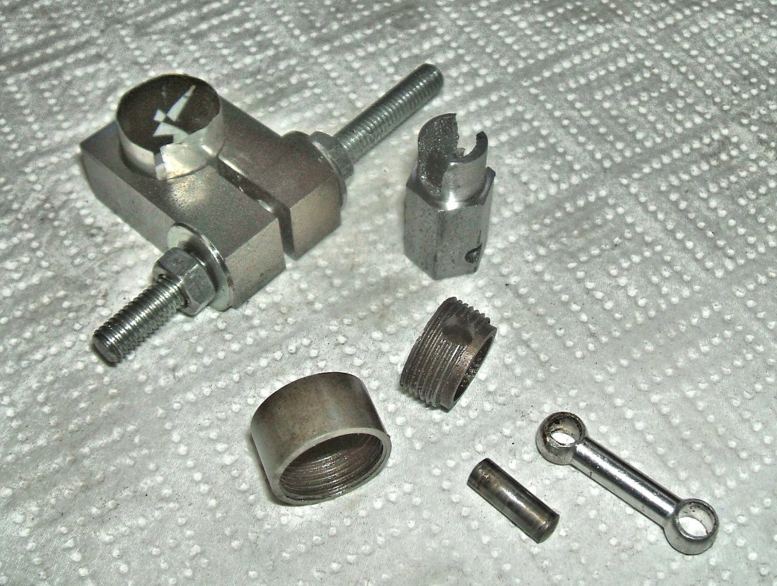 A mild steel mandrel will also need to be made to hold the new piston cap for honing or lapping to finish prior to assembly. Use 3/4" round stock and turn down and thread one end to match the external dimensions of the carrier, making sure the old cap screws on correctly, so the mandrel can be used to check the fitting of the new cap and to hold it for honing to the final finish. When cutting the threads inside the new cap, it's critical to ensure that the carrier seats firmly to the underside of the cap, primarily to maintain the correct timing but also to ensure that the small amount of metal above the gudgeon pin hole in the carrier is fully supported. Any gap caused by the cap unscrewing or not fitted correctly in the first place will result in the gudgeon hole elongating and breaking the ring. No prizes for guessing how I found out about that particular wrinkle!
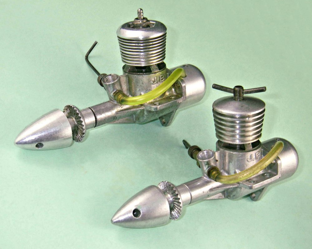 I should also mention that the 1.5 cc JB Atom diesel and its glow-plug Atomglow relative use a similar system. However, the gudgeon pin carrier in that case is light alloy rather than steel. The piston cap in that engine was hardened steel, as was the cylinder. Unfortunately, they were set up very much on the tight side. As a result, the combination of hard steel running in hard steel took forever to run in. In many cases the rest of the engine would wear out before the piston/cylinder fit was run in!
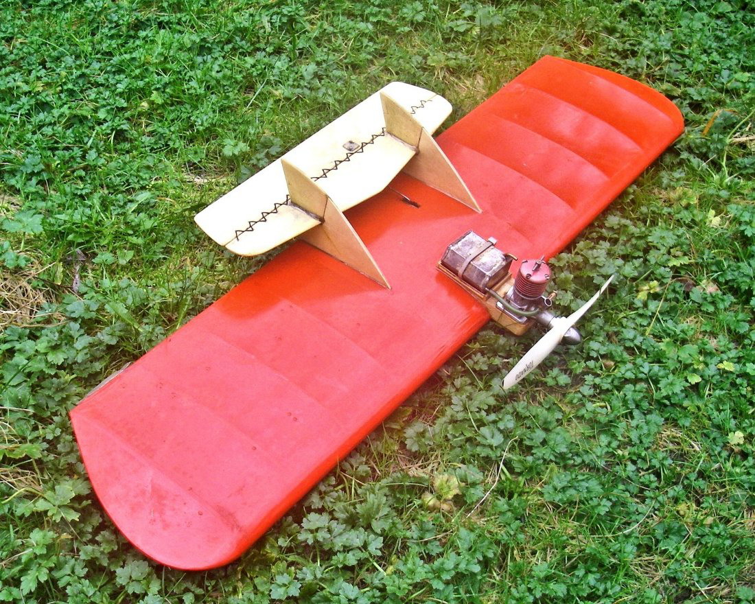 The result of this work is a very worthwile reduction in the engine's reciprocating weight from 12 gm to 7 gm. When taken together with a minor addition of couterbalance achieved by grinding
 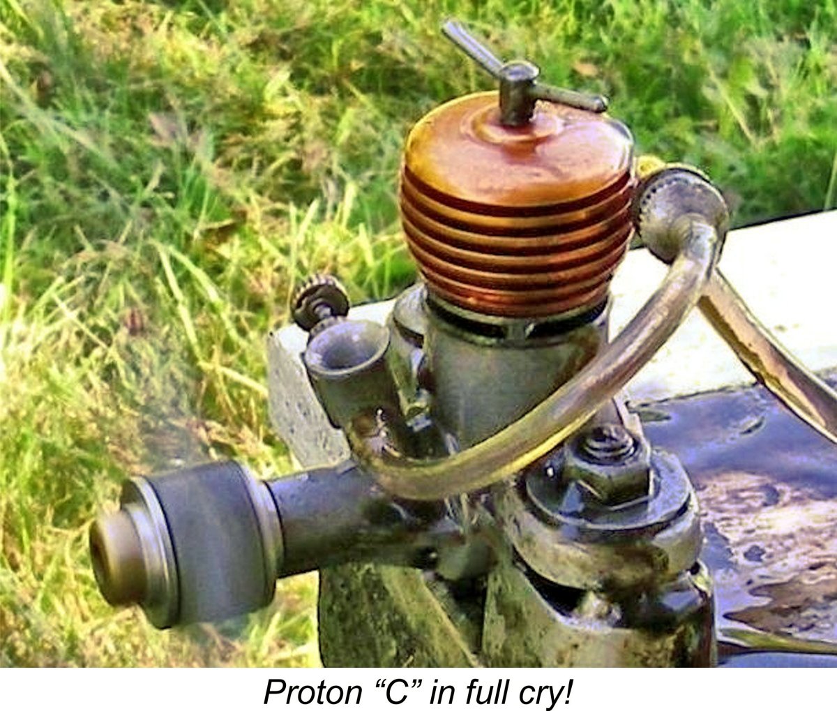 In the end, it comes down to a question of whether originality or performance is your priority. If the latter,
 | |