
|
|
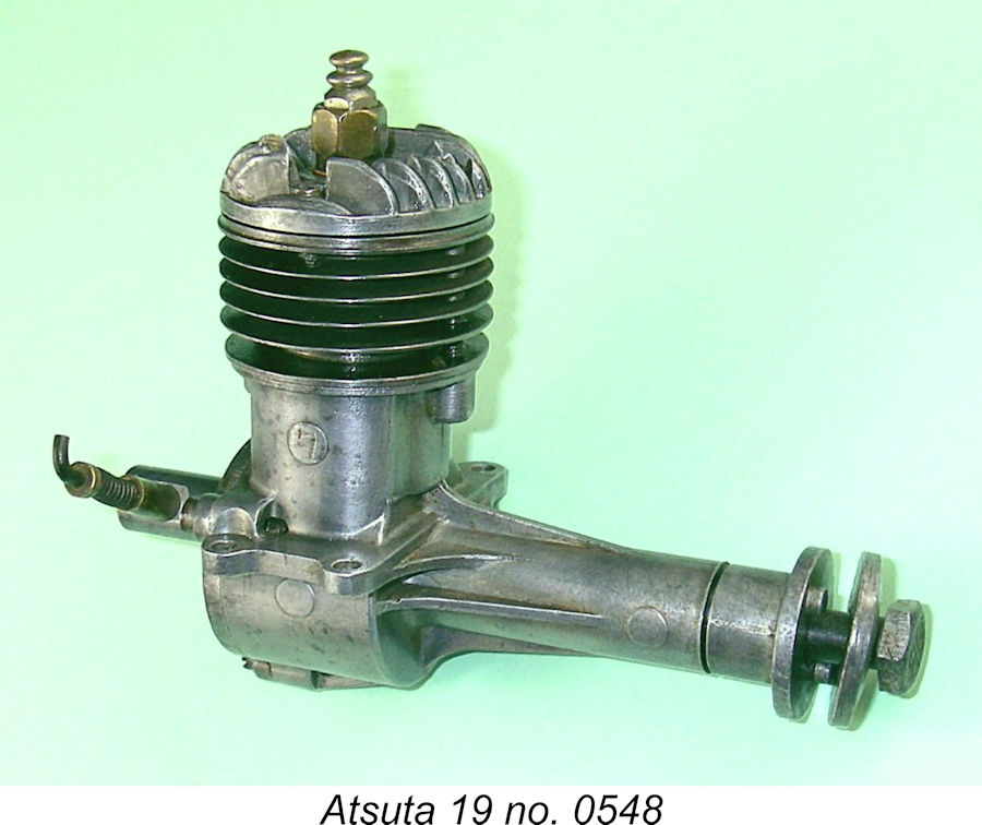
Japanese Long-shaft Rarity - the Atsuta 19
The very existence of the Atsuta engines never appears to have become apparent to contemporary observers outside Japan - despite an intensive search, I can find no mention of them at all in the English-language modelling media of the day. There’s little doubt that the engines were never marketed outside Japan, although a few may have found their way to other countries through such routes as personal purchases by members of the post-WW2 forces of occupation. Even in Japan itself, the marque never appears to have achieved anything approaching mainstream status, possibly being marketed on a strictly regional basis. For this and other reasons (to be discussed below), the Atsuta engines are extremely rare today even in Japan and are almost never encountered elsewhere. I acquired the illustrated example from a Japanese source. This being the case, there’s less than usual to say about these rare but refreshingly out-of-the-rut engines. It has however been possible to learn a little about them from contacts in Japan, in which regard I’d like to record my indebtedness to my friend Rudy ni Balinia (from whom I obtained this example) as well as Akira Fujimuro, one of the key figures in the post-war Japanese model engine and model aircraft fields. Despite the combination of distance and the language barrier, both of these gentlemen assisted me greatly in my attempt to learn more about the Atsuta marque. Even in Japan, detailed information about these engines appears to be rather scanty. Let’s see what we can do to draw aside the veil a little …… Connotations of the Atsuta Name
The Atsuta district has long been associated with the famous Atsuta-jingū (Atsuta Shrine), a major Shinto shrine traditionally believed to have been established over 1,900 years ago during the reign of the Emperor Keikõ (71-130 CE). This is one of the most Given the instant geographic recognition factor attached to the Atsuta name, its application to the model engines with which we are dealing would immediately imply to any contemporary Japanese citizen that they were manufactured in Nagoya. Further recognition of this would have come from the existence of a full-sized precedent in the form of the WW2-era AE1A Atsuta aero engine, which was a licensed version of the German Daimler-Benz DB 601, a 12-cylinder liquid-cooled inverted-vee aircraft engine which was used to power the Since the Aichi Aircraft Company was dissolved following the conclusion of WW2, it appears that the Atsuta model engines had nothing whatsoever to do with that company or its descendants. The latter-day descendant company of the Aichi Aircraft Company is the Aichi Machine Industry Co. Ltd. (no mention of Atsuta), which manufactures automotive parts and light trucks for Nissan. Nonetheless, the name Atsuta would have retained a strong aviation-related connotation among air-minded Japanese people as of the early 1950’s. For both of the above reasons, the use of the name Atsuta was entirely appropriate for a model engine range manufactured in Nagoya. It combined the name of a nationally-famous and widely revered location with a very direct connection to Japanese aviation history. Production of the Atsuta Model Engines
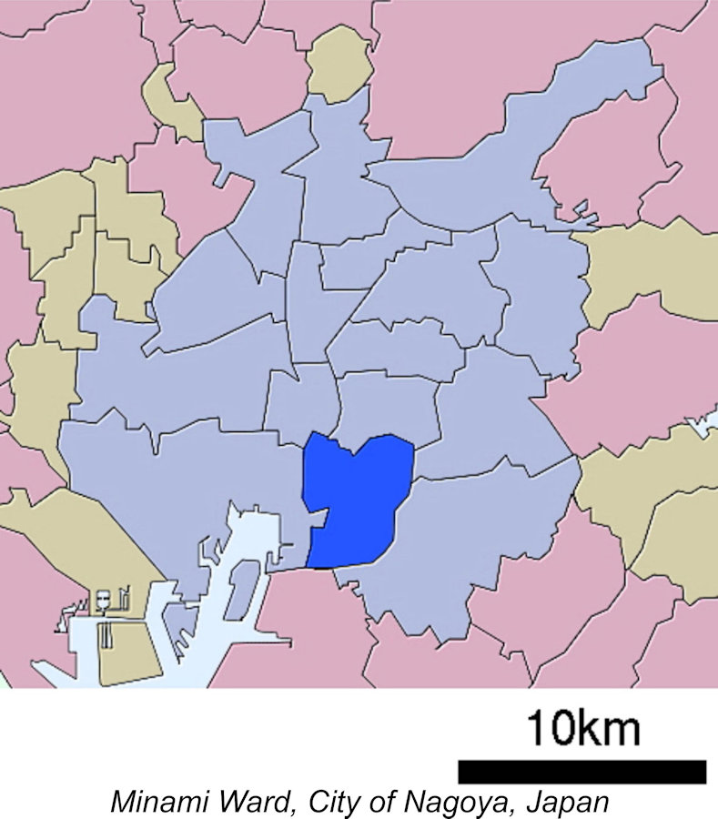
During the years following WW2, the Minami ward developed into a major centre for heavy industry, including a Mitsubishi Motors plant which remained in operation until 2000. It’s thus scarcely surprising to find a precision model engineering venture being located there.
Information received from Japan suggests that the Atsuta 19 was the only model ever produced by this manufacturer. According to Akira Fujimuro, the Atsuta engines were manufactured on a modest scale in a small workshop as opposed to a major factory. At this point in time over 70 years on (as of 2023), the identity and background of the individual(s) responsible for the Atsuta model engines remain obscure, probably being lost forever at this stage. It would be nice to think that some of those who had been involved with the full-sized Atsuta aero engines may have had some involvement with the model aero engines which came later, but we have no evidence for this.
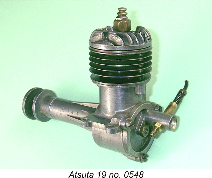
Another circumstance supporting t There is also considerable uncertainty regarding the issue of production figures. Akira Fujimuro stated his belief that the numbers manufactured were very small - perhaps between 300 and 500 examples. However, if this impression is accurate, then we face a serious difficulty with respect to interpretation of the known serial numbers. My own illustrated example bears the serial number 0548, which seems fair enough. However, thanks to Rudy ni Balinia I also have images of similar engine number 3250. If there was no break in the serial number sequence, this would clearly imply the production of at least 3250 examples. Only the uncovering of more serial numbers would help us to resolve this question. Given the engine’s extreme rarity, I’m not holding my breath ……. The Atsuta 19 - description In writing this section of the article, I am at last on firm ground, since I have an actual example of the Atsuta 19 to examine and test as well as a contemporary image showing the engine in component form. This is just as well, since I was unwilling to disturb this near-pristine example beyond the removal of the backplate to examine the induction and crankcase arrangements. My reasons for this decision will become clear as we proceed.
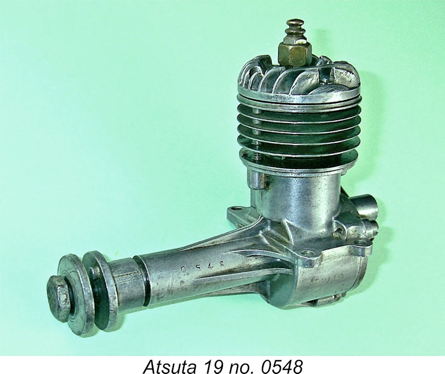
Apart from the serial number, the only marking that appears on the engine is the Greek letter η (eta) which appears in a small circle cast in relief onto the right-hand side of the upper crankcase. This letter is the International symbol for "efficiency". The Atsuta's displacement figure is interesting insofar as it puts the engine just above the displacement limit for American Class A competition. This is another indicator of a relatively early date - by the early 1950’s almost all Japanese manufacturers were designing their engines to conform to US competition classes. This was becoming important even in Japan itself, where the ongoing presence of the predominantly American forces of occupation led to many domestic contests being flown to US rules. The Atsuta 19’s bore and stroke measurements result in unusually over-square geometry for an engine of this vintage, although there are precedents. Even so, it seem possible that the designer(s) may have been retaining the option of adding an under-bored 2.5 cc (.15 cuin.) version at some point using the same bottom end. A bore of 14.7 mm combined with the same 14.6 mm stroke would yield a displacement of 2.48 cc with square internal geometry. However, my Japanese informants believed that only the 19 ever actually appeared on the market.
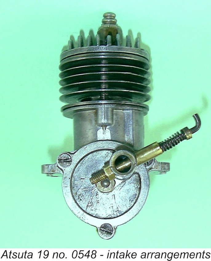
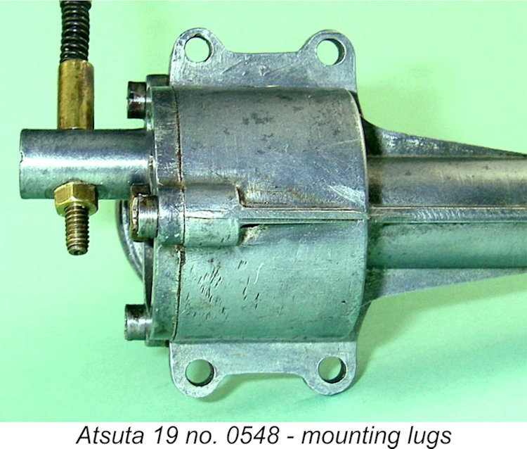
The crankcase is a clean pressure die-casting which incorporates the main bearing in unit. The most obviously out-of-the-rut feature is the unusually long main bearing. It seems likely that the idea was to make the engine more amenable to tidy installation in a long-nosed scale or semi-scale model. The use of RRV induction would also support this goal by creating a front end which is completely free from any protuberances. The combination of a plain bearing with a rather basic disc valve design argues strongly against any notion that racing applications featured in the designer’s ambitions. The accompanying component view of engine no. 3250 should do much to clarify the following description. That example appears to have a Fuji needle valve assembly in place of the original components seen on my own example and in the previously-reproduced advertising image.
The head and cylinder are both secured to the crankcase by a pair of long screws which pass through clearance holes drilled through the cylinder head, cylinder cooling fins and location flange to engage with two tapped holes in the crankcase casting fore and aft. Two additional shorter screws are placed at the sides of the head to assist in the maintenance of a head seal. These thread into tapped holes formed in the relatively thick upper cylinder flange. This assembly appears unusually open to distortion during the assembly process, particularly given the combination of unevenly-distributed hold-down stresses, very thin cylinder walls, thin cylinder installation flange and the extremely wide exhaust port which removes much of the support from the upper cylinder wall and cylinder installation flange on the exhaust side. There is no trace of binding in the illustrated example, and I was keen to keep it that way! It was largely for this reason that I elected not to disturb the cylinder assembly, at least at this stage. The cylinder porting is somewhat unusual, albeit not atypical in an early post-war Japanese context. Both exhaust and transfer ports are milled through the relatively thin cylinder walls to create rectangular openings of unusually large area. The exhaust opening is cut above the cylinder location flange, while the transfer port is cut below the flange. This would preclude the creation of any overlap between the two ports were it not for the use of a step cut into the crown of the cast iron piston on the transfer side. As can be seen in the attached image of the engine in component form, this step is crescent-shaped rather than being cut straight across - a good design feature, since the width of the transfer port would otherwise require a step of unusually large width and volume, to the great detriment both of transfer gas velocities and combustion chamber shape. As it is, the narrow crescent-shaped step provides excellent directional control over the incoming transfer gas, along with enhanced gas velocity.
On the downside, the fact that the combustion chamber is a simple shallow dish with no features to promote swirl around Top Dead Centre will do nothing to enhance combustion efficiency. Moreover, the engine’s measured geometric compression ratio is an unusually modest 6.5 to 1, a seemingly marginal figure for a glow-plug engine. This parameter alone suggests that high operating speeds were not envisaged. As a result of the presence of the step in the piston crown, there is considerable overlap between the exhaust and transfer ports, without the need to open the exhaust port unduly early. Timing figures are thus reasonably conservative, the exhaust being open for some 140 degrees of crankshaft rotation, while the transfer period is some 110 degrees. These numbers are entirely appropriate for the relatively modest speeds for which this engine appears to be designed.
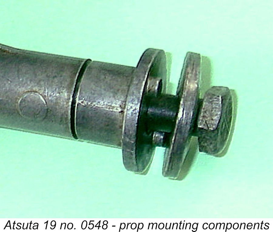
The fully-floating gudgeon (wrist) pin has a seemingly rather minimal diameter of only 3 mm. The piston drives the crankshaft through a At the front of the engine, the prop driver is another clean pressure die-casting which is driven by the shaft through a self-releasing taper. Another feature which seems to date this engine to the early 1950’s is the use of two integrally-cast pins to prevent prop slippage instead of the more conventional knurling of the prop driver face. The prop is secured in place by a steel bolt which threads into a hollow portion of the shaft at the front.
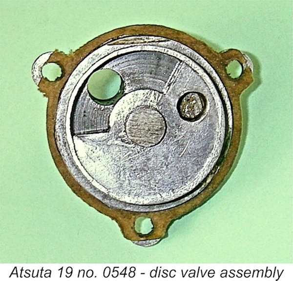
The actual induction port in the backplate is a simple round hole, no attempt being made to contour it for enhanced gas flow. In order to achieve the desired timing, the window in the disc itself is unusually long, giving a full 180 degree induction period (30 degrees after bottom dead centre to 30 degrees after top dead centre). This appears to be an entirely appropriate induction timing period.
To maintain access to the needle valve control if the re-configured engine is to be used in an upright mounting orientation, it will be found necessary to remove and re-install the needle valve assembly from the opposite side of the venturi. In this form, the venturi will be located at the bottom of the backplate as assembled, with the needle valve assembly in a near-vertical orientation. Considerations of torque balancing could potentially make this a very useful option in a multi-engine scale or semi-scale model context.
All fits and finishes in the illustrated example are well up to the best contemporary commercial standards. Although it has clearly been mounted and used, the engine remains perfectly fitted throughout, turning very freely with the plug removed but with no detectable play anywhere in the system. With a plug fitted, compression seal is excellent, as is the base compression seal. A point to note in connection with this engine is the fact that the crankshaft end float appears to be rather critical. The axial clearance provided for the connecting rod big end and spacer to fit between the crankweb and the disc valve is minimal. Consequently, if the shaft and rod are not to bear on the alloy disc when set back during starting or when operated in pusher mode as suggested in the advertisement, then end float has to be kept small enough to ensure that the rear of the prop driver absorbs any set-back forces. Otherwise, a condition would be created whereby the disc valve would in effect become the thrust bearing, which is bound to cause high levels of friction along with accelerated and/or uneven disc valve wear. Many examples of the E.D. Bee diesel and its Hornet relative suffer drastically from this problem. On the other hand, there needs to be enough end float to ensure that lubricant has free access to (and passage through) the extended main bearing, for which lubrication is likely to be a rather critical issue. My example has about 0.2 mm end float, with very little leeway in either direction as far as I can tell. If the engine was to be used in pusher mode, I would definitely recommend the use of a thin steel thrust washer between the rear of the prop driver and the front of the main bearing. Otherwise, the situation would be an alloy-on-alloy thrust bearing - not a recipe for longevity. It appears that the engine may have been fitted with such a shim as supplied - engine number 3250 seen in the earlier component view clearly had such a thrust washer, since it’s present in the photograph. I suspect that my example is simply missing this component. If the engine is used in normal rotation mode with a tractor prop, this washer is of course unnecessary. The other point worth noting is that this appears to be one engine which is definitely best left undisturbed once settled down and run in. The cylinder design with its two main hold-down bolts, thin walls and oversized exhaust port is such that the cylinder is almost guaranteed to take a “set” when first tightened down. If it is subsequently disturbed, there is little chance that the exact same “set” will be re-established upon reassembly, with potentially negative consequences on both performance and longevity. Best left well alone ………….. Apparent Design Problems We've noted the unconfirmed possibility that over 3000 examples of the Atsuta 19 may have been made in total. If this is indeed the case, the next question must be - where are they all now?? Why is this engine as rare as it appears to be, even in its native Japan?
For this reason, it seems likely that a substantially higher than usual incidence of crash damage bedevilled the Atsuta 19. If the engine was marketed at a competitive selling price, this may have led to damaged examples simply being discarded rather than being seen as having sufficient monetary value to be worth repairing. However, it appears that the real culprit may have lain elsewhere. According to Akira Fujimuro, most of the Atsuta engines failed in service because of inadequate lubrication reaching the front end of the very long plain-bearing shaft. This resulted in damage to the shaft and bearing, sometimes extending to catastrophic If this is how things went, then the supply of spare parts would also have been terminated early on. This in turn would explain why any examples that subsequently broke their cases were discarded - spare replacements were simply not available. Either way, it appears that an unusually small proportion of the engines that were manufactured have survived down to the present day. Those of us lucky enough to own examples will need to take very good care of them! In particular, anyone (like myself!) who is planning to run one would do well to lubricate the front of the main bearing before each and every run and also make sure that there is a little clearance at the rear of the prop driver to provide some end-float, thus allowing the free passage of lubricant into and out of the bearing. In view of the likely identity relationship between the Atsuta model engines and their full-sized Daimler-Benz based Atsuta predecessors from WW2, it’s interesting to note that the full-sized Atsuta engines also experienced serious crankshaft problems. The design of the Daimler-Benz originals from which the Atsuta engines were copied was such that the fit and alignment of the crankshaft in its bearings was critical given the greater than average length of the engine. The Japanese manufacturers appear to have had difficulty building the engines to the required tolerances. Postwar evaluation by the US Air Force’s Foreign Aircraft Evaluation Center found that the standard of workmanship displayed in the Atsuta aero engines was not as good as that of the Japanese Army's Kawasaki Ha-40 and far worse than that displayed by competing engine makers Mitsubishi and Nakajima. There was also the issue of the quality of steel available to the Japanese during the war, which fell somewhat short of that specified by Daimler-Benz. The overall result was that the full-sized Atsuta engines proved to be somewhat prone to crankshaft failures. Despite this, the Aichi company managed to produce some 873 Atsuta series engines during World War II before repeated Allied bombing of the Atsuta engine plant eventually brought engine production to a standstill. The Atsuta 19 on Test - Finally! After ten years of agonizing (aka procrastination!) in view of the cautionary note of some of the earlier comments, I finally decided to take the bull by the horns and give my example of the Atsuta 19, engine number 0548, a chance to show what it could do. The state of the piston crown confirmed that it had clearly survived a fair bit of previous running, leading me to hope that it could take a little more.
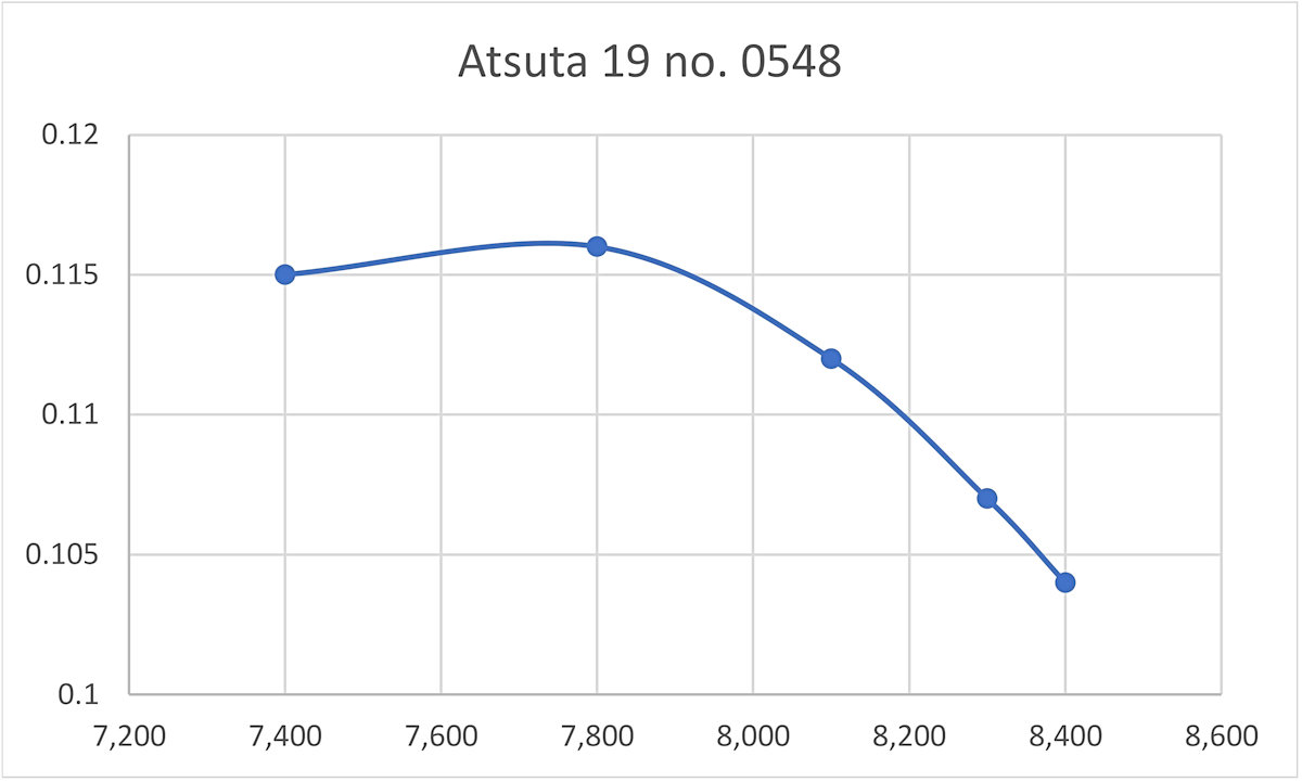
Following the administration of a port prime, the engine started immediately. At this point, I got my first indication that the compression ratio was too low - the engine slowed down noticably when the plug driver was removed. This is a classic symptom of an excessively low compression ratio. Once warmed up, however, the Atsuta settled down to run very smoothly at a rich setting. I secured the accompanying photo and then tried the effect of leaning the mixture. The engine sped up initially as expected, but then suddenly stopped dead! My initial fear was that the infamous shaft had seized solid, but thankfully this fear proved to be unfounded. The engine still turned over freely, with the piston still moving up and down, indicating that nothing had broken. However, all traces of compression had disappeared completely. The investigation of the cause of this set-back naturally required me to remove the head and cylinder, something which I had previously been reluctant to do for the reasons explained earlier. However, needs must ......... the problem turned out to be a blown head seal. A previous owner had installed a poorly-cut home-made head gasket made of some rather dubious fibre material which appeared to have deteriorated over time. This was quite unlike the narrow ring seal visible in the previously-reproduced component image. It was this gasket that had blown. The same owner had also installed an equally poorly-cut and seemingly insecure base seal below the cylinder installation flange. A look at the component view showed that the original head seal was a narrow ring, presumably metallic - a fibre ring of that width would blow immediately. A narrow annular sealing face protruded slightly above the upper surface of the cylinder, surrounding the bore. I found that a soft copper cylinder base gasket from an OK Cub .099 was an exact fit over this sealing surface, looking as if it was made for the Atsuta! I lapped the So without delay, back into the test stand it went! Things went much better this time - the engine started immediately just as before following a port prime, although it continued to sag a little when the plug driver was removed. However, it could now be leaned out with no evidence of any head seal leakage. The Atsuta was to maintain its excellent starting behavior throughout the test sequence, firing up first or second flick every time following that seemingly essential port prime. I continued my practise of applying penetrating oil to the front of the shaft before each run, although I detected no evidence of any incipient seizure at any time. This particular well-used example was evidently supplied with an appropriate main bearing fit, which probably explains its survival to the present day despite the previous use to which it appears to have been put. Once leaned out, the Atsuta ran very smoothly on the APC 9x6 prop with which it was fitted. However, I noticed that when the engine was fully leaned out, the speed kept rising for some time with no change in the needle setting as the operating temperature increased after the establishment of smooth two-stroke operation. With a glow-plug motor, this is a classic indication of a compression ratio that is lower than ideal. It was immediately Hoping for better things at higher speeds, I tried a few smaller loads. However, this proved to be the wrong way to go - as speeds increased, a misfire crept in which couldn't be eliminated with the needle. The symptoms suggested that the engine had run past the limits of the ignition timing imposed by its very low compression ratio. This impression was confirmed by a switch to an APC 10x4 prop, which the engine spun very happily at a dead smooth 7,400 RPM. Not wishing to beat up on this very rare unit unnecessarily, I terminated the testing at this point. There appeared to be no reason why the Atsuta wouldn't take some more running in its stride, but why risk it with such a rare engine? In the end, the following data were obtained:
While the above data can in no way be viewed as fully comprehensive, it appears that the engine had been operating very near its peak on both the APC 10x4 and 9x6 airscrews. Indications are that the Atsuta developed around 0.117 BHP @ 7,700 RPM. Beyond that point, the engine appears to go into under-compressed mode, being very reluctant to run much past 8,000 RPM. Apart from the limitation imposed by the very low compression ratio, the engine's combination of a very short stroke with a clearly inefficient combustion chamber doubtless play a role in restricting its torque development.
Conclusion The rarity of the Atsuta model engines, particularly outside Japan, is such that few collectors will ever see one, far less own one. Despite this, these engines seem to me to be well worth noting, since they undoubtedly constitute a hitherto-unreported piece of the overall picture of Japanese model engine manufacture during the early post-war period. Moreover, their unique combination of design features places them well outside the rut, reflecting a refreshing willingness on the part of their unknown manufacturers to think outside the box as it then existed. ___________________________________ Article © Adrian C. Duncan, Coquitlam, British Columbia, Canada First published December 2014 Updated September 2018 Second update - June 2025 - bench test |
||
 In this article I'll unveil a model engine marque which as far as I can tell has completely escaped previous notice among model engine enthusiasts outside its country of origin. I’ll be discussing the Atsuta glow-plug engines which were manufactured in small numbers in Nagoya, Japan during the early 1950’s.
 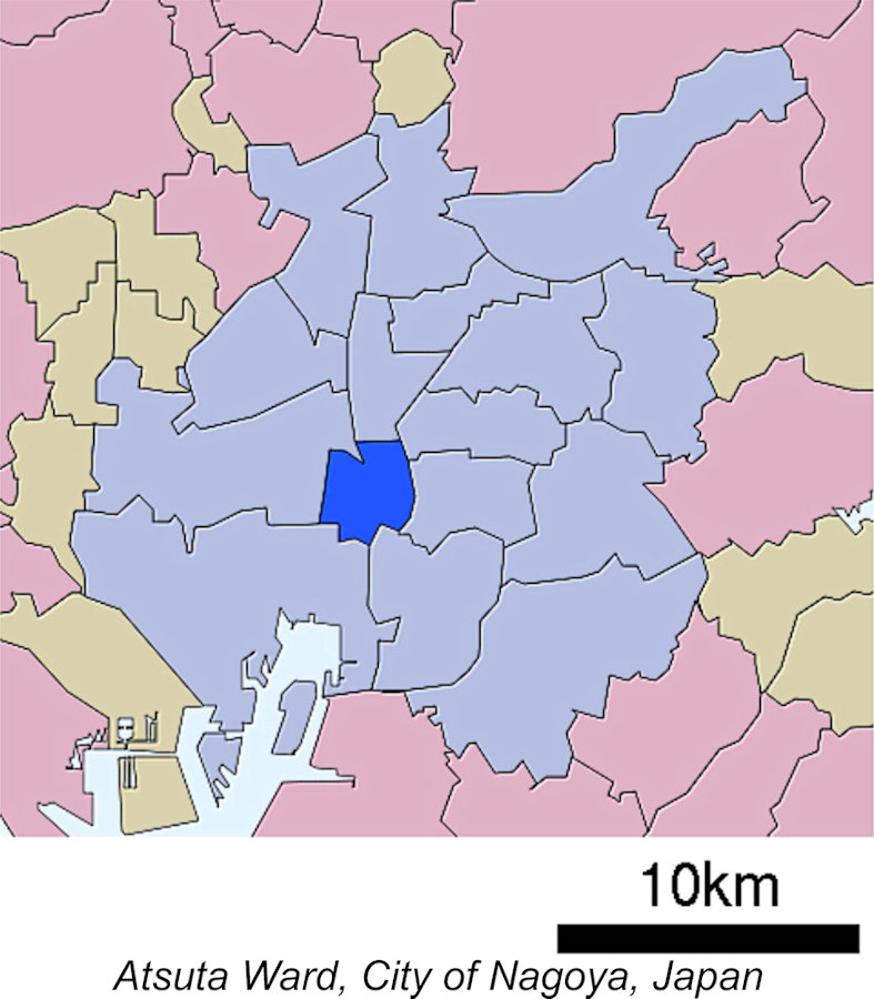 The name Atsuta is very closely identified with the City of Nagoya in Japan’s Aichi Prefecture. Like all major Japanese cities, Nagoya is organized into a ward system, with Atsuta-ku (Atsuta ward) being one of the more centrally-located of the 16 wards into which the city is divided. Today it is one of Nagoya’s major commercial and industrial districts.
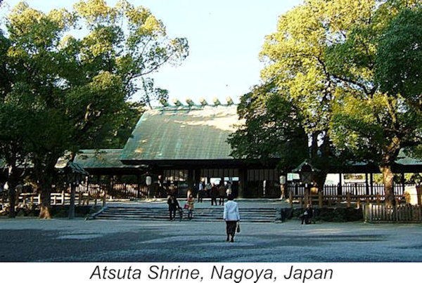
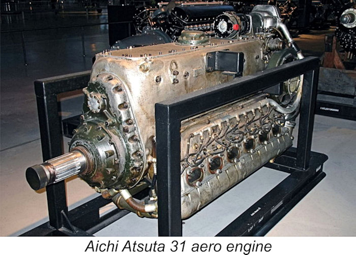 Messerschmitt Bf 109 and Bf 110 aircraft. The licensed Japanese copies and their derivatives were manufactured between 1938 and 1944 by the Aichi Kokuki KK (Aichi Aircraft Company) at its Atsuta Engine Plant in Nagoya, being named for that location. They were used to power a number of well-known Japanese warplanes during WW2.
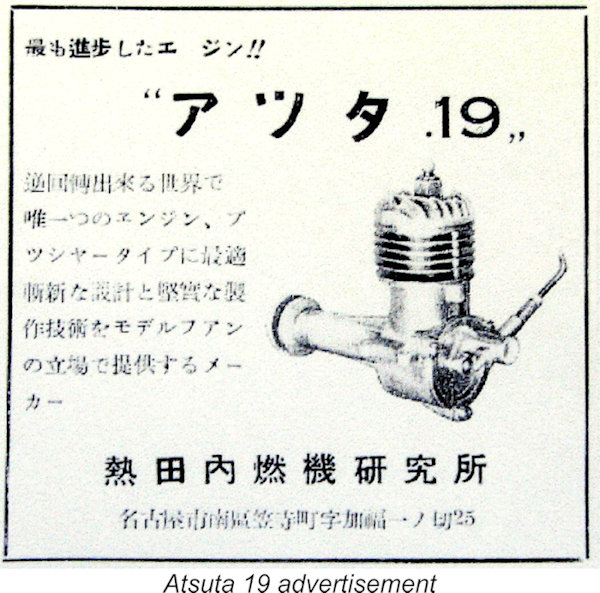
 The precise production period appears to be the subject of some uncertainty. My Japanese informants told me that the engines were produced over a relatively short period of time at some unspecified point during the 1950’s. Looking at the engines in architectural terms, I would hazard a guess (which is all that it is) that they most likely date from the early fifties. By the middle of that decade they would have been considered very “old-fashioned” indeed by emerging contemporary model engine design standards, both in Japan and elsewhere.
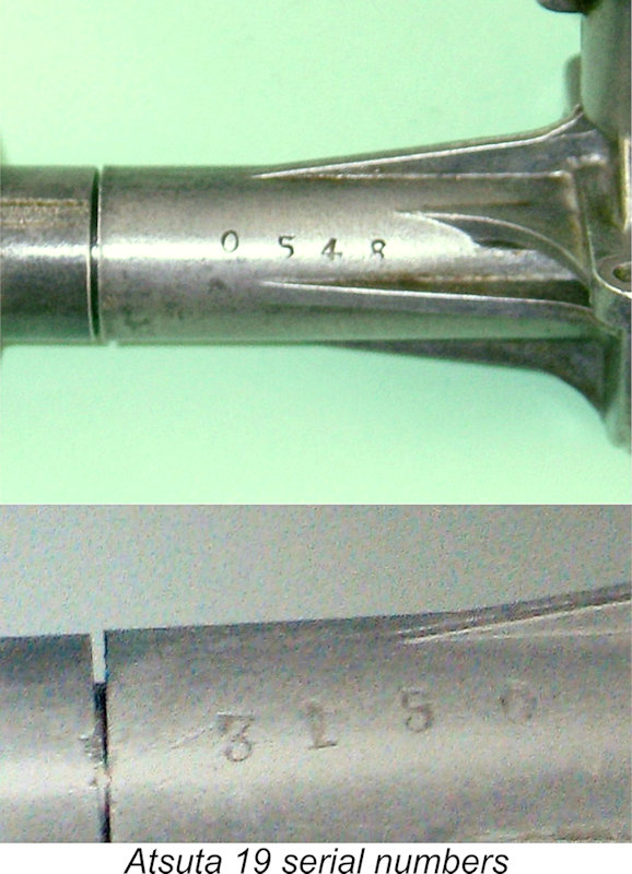
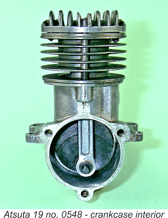
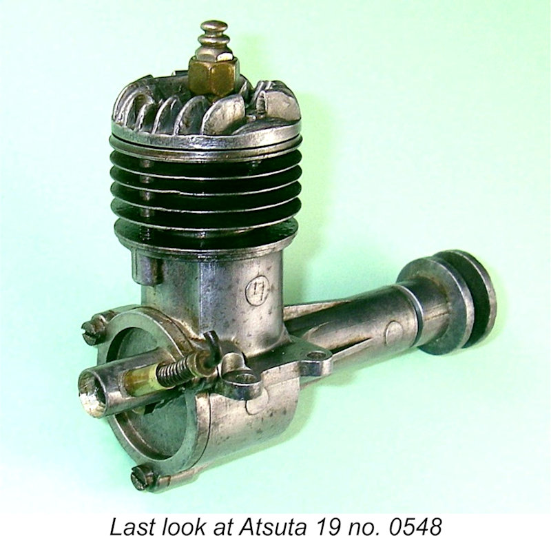
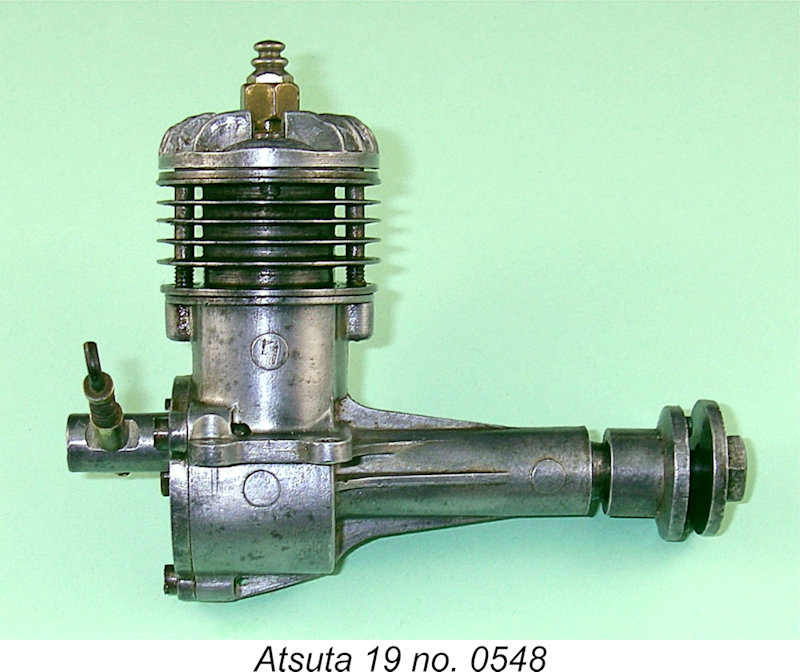 The Atsuta 19 is a short-stroke plain bearing lightweight glow-plug motor having a number of features which place it well out of the rut in design terms. We may as well start with a few vital statistics. The officially-quoted bore and stroke were 17.0 mm and 14.6 mm respectively for a displacement of 3.31 cc (0.202 cuin). My example checks out at exactly these figures. The weight of the engine (with plug) is a commendably light 140 gm (4.98 ounces).
 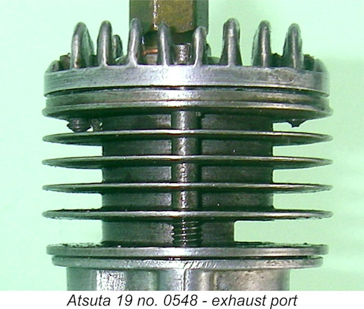 At first glance one might be forgiven for believing that this engine was a radially-ported design - the absence of an exhaust stack together with the general style of the cylinder would appear to imply this. However, in reality the engine is basically a conventional cross-flow loop scavenged unit featuring a plain bearing along with disc rear rotary valve (RRV) induction. The very wide rectangular exhaust port is "hidden" between the lowest cooling fin and the cylinder installation flange, as the accompanying profile view will confirm.
 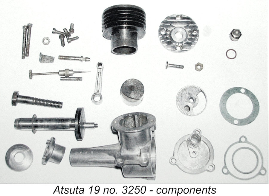 The engine features a steel cylinder of typical Japanese form by late 1940’s/early 1950’s standards. The cooling fins are machined integrally with the cylinder itself. The cylinder is located on the top of the crankcase casting by a relatively thin location flange which seals with a fibre gasket. The cylinder head is a separate aluminium alloy component which is produced by pressure die-casting, a technology with which the manufacturer was clearly very comfortable. A narrow soft metallic gasket is used to create a head seal.
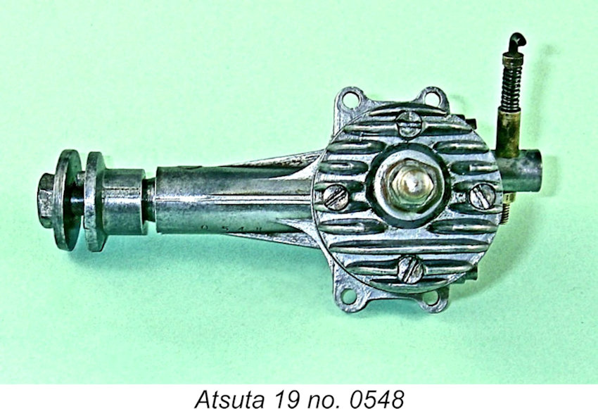 Even so, the presence of the step does compromise the shape of the combustion chamber at top dead centre by creating a pocket of gas on the transfer side well away from the ignition source. To mitigate the adverse effects of this feature, the plug is displaced to the transfer side to reduce flame propagation distance to this pocket, thus speeding up its involvement in the combustion process. Another very intelligent design feature …….
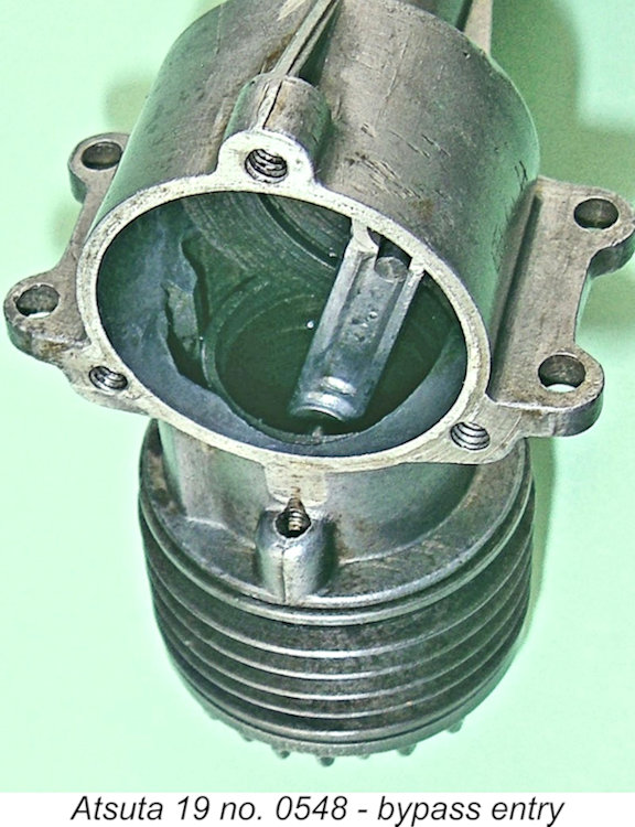
 failure. Such an issue would quickly have become apparent to contemporary users, a fact which would have done nothing to enhance the engine’s chances of marketplace success. It may have been this issue as much as anything else which led to the seemingly speedy withdrawal of the Atsuta 19 from the market.
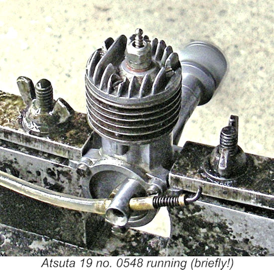 Accordingly, I set it up in the test stand with a 9x6 APC prop fitted. In deference to the engine's very low compression ratio, a "hot" Fox plug was used together with an oily castor-based fuel containing 15% nitro. Although the shaft felt completely free, I applied a liberal dose of penetrating oil to the front of the main bearing before commencing operations, just to be sure. It was my intention to do this before each and every run.
 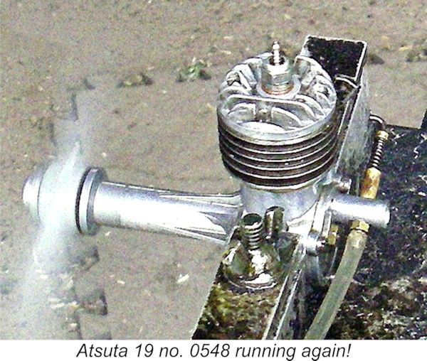 head onto the cylinder's sealing surface and then reassembled the engine with the OK copper gasket in place beneath the head and a properly-cut fibre base gasket beneath the cylinder. Success!! The head sealed perfectly, and there was no evidence of cylinder distortion. The engine was all ready for another try.
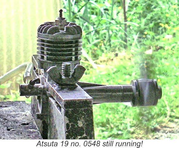
| |