
|
|
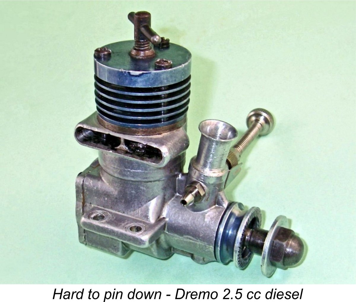
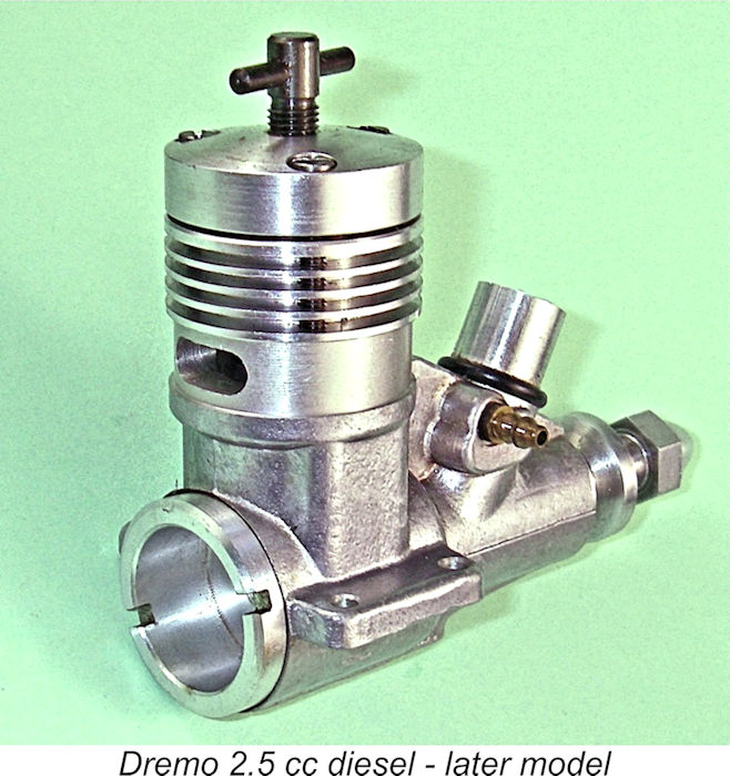
Re-discovered 2.5 cc Diesel - the Dremo 2.5 cc Side-Stack Model
Doug was a former acquaintance and trading partner of mine who started collecting engines (including diesels) way back in the 1950’s before anyone knew that there even was such a thing as engine collecting! Moreover, no-one in North America apart from Doug and a very few others (including me from 1966 onwards!) was interested in diesels back then or for some decades thereafter, leaving the likes of Doug and (later) myself with a clear field in the diesel acquisition department. As a result, Doug ended up owning many extremely rare or elusive diesels such as this one.
This said, this particular motor proved on examination to be a very well-made unit having so many interesting and potentially historically significant design features that I felt it to be worth going all the way in documenting it and seeking further information from as wide a range of sources as possible, namely, my esteemed readers. The engine’s rarity is underscored by the fact that in well over 40 years of looking I’d never previously seen as much as a picture of an example. Given the relative rarity and technical interest of side-stack diesel designs, I found this very surprising - if I'd seen it, I would certainly have taken note. To further my research, I published an article on this website which included both a detailed illustrated description of the engine and a performance assessment. My hope was that someone who read that article would come up with a well-supported and authoritative identification of the maker of this obscure and seemingly mega-rare motor. In the end, that effort paid off handsomely, but it was a surprisingly long haul! I think it's worth setting out the course of my inquiries in this instance both to establish the engine's identity beyond doubt and to give readers an idea of how challenging the identification of a rare and undocumented engine like this can actually prove to be! The main thing to keep in mind is that there's always someone who knows - it's just a matter of connecting with that person. There's no substitute for persistence....... and as a bonus I made a lot of new friends along the way! The Quest for Identity Undocumented engines of this rarity and obscurity often turn out to be one-off home-builds by a now-unidentifiable maker. In the present case, this attribution seemed highly unlikely for a number of reasons. First there was the colour anodizing, a somewhat unusual refinement in a home-build, especially one of this engine's architectural era. Secondly, there were the three castings, all of which are produced as gravity die-castings. Few home builders would go to the trouble of making multiple dies for a one-off. In addition, the engine exhibited a number of minor detail manufacturing flaws which were typical of series-production or experimental models but seemed to me to be unlikely to have been left unattended by any talented and self-respecting home constructor. Finally, there was the general style of construction and finish, which of course has to be seen at first hand to be fully appreciated. On the basis of my own long and varied experience, I felt from the outset that the manufacturing processes which had been used as well as the quality and character of machining, finish and heat treatment were far more characteristic of a production item than a one-off. Wherever and by whomever it was made, the engine was remarkably elusive - it even escaped the attention of 2.5 cc guru Jim Dunkin (not a mis-spelled relation of mine!), whose wonderful book on the subject of the world's 2.5 cc engines doesn’t miss much but doesn’t include this one. I checked directly with Jim, who confirmed that he had no prior knowledge of this unit or its origins. I then ran the engine past a number of my more knowledgeable fellow enthusiasts worldwide, several of whom claimed to have "seen it before" but none of whom were able to put a name to it. From the outset, the use of metric threads throughout sugested an Asian or Continental origin. A Japanese origin seemed highly unlikely for a variety of reasons, most notably the style of the castings, which is very atypical of Japanese practise. Everyone agreed that the engine appeared to be a European product of the late 1950's. However, given the level of interest in vintage European engines, no-one could understand how it could be eluding identification as comprehensively as it seemed to be doing.
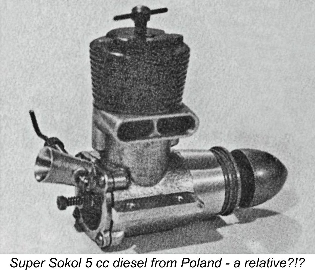
In order to pursue the possibility of a Polish origin, I signed up on a Polish modelling forum which included a lengthy and very interesting thread on the little-documented subject of Polish model engines. This was quite easy to do, and the use of Google's translation facility renders the site completely intelligible to an English-speaking reader like myself. I was warmly welcomed desipite my non-Polish location - in fact, I was very pleased to learn that many Polish model engine enthusiasts are regular readers of my own website! However, no-one on the Polish site could identify this engine. They agreed that the treatment of the exhaust stack is similar to that of the Super Sokól, but stated that none of the engine's other design features corresponded in any way to any of Górski's documented design work. They stated further that if this was a Polish engine, whether by Górski or anyone else, one or more of them would definitely know about it. So although Robert's suggestion certainly had considerable merit, it appeared that a Polish origin was ruled out. Meanwhile, two correspondents independently noted a few features, most notably the style of the upper crankcase below the exhaust stack and the large-diameter main bearing housing, which they claimed to be characteristic of the earlier work of the talented constructor Hans Drenkhahn of East Germany (as it was then), who established the Dremo marque. I checked with a few of my German contacts, but they were unable either to confirm this identification or suggest a German alternative.
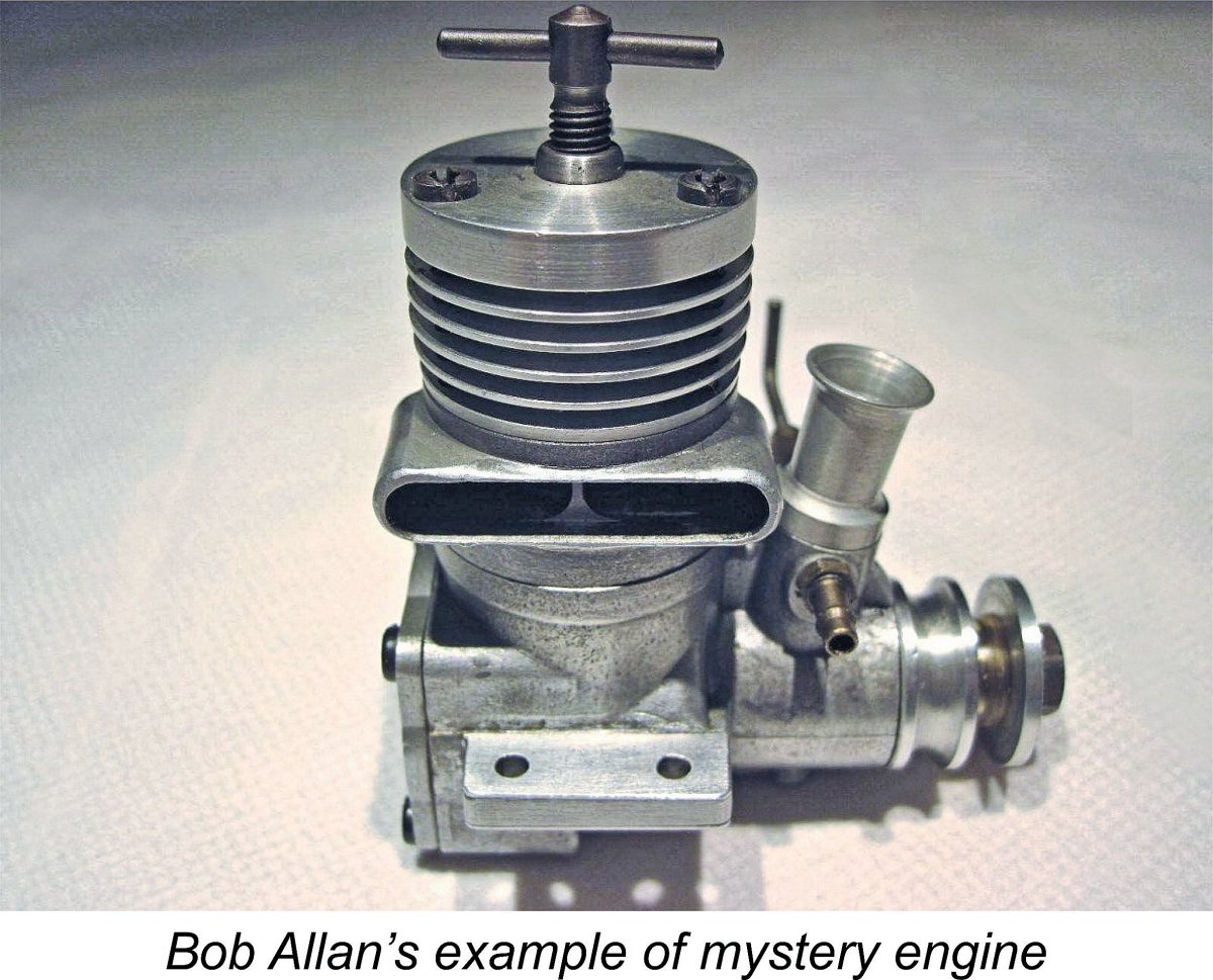
In support of his suggested identification, Bob cited the very unusual head fasteners as a potential clincher, quoting a comment from a German collector which had been posted some time previously regarding a larger "mystery engine". This quote read as follows: "The mystery engine (not my unit, please note!) is a 10 cc Dremo, made by Hans Drenkhahn. The head screws are not original - usually they should be threaded bolts with special slit nuts" It's the latter observation which led Bob to suggest that this is an undocumented 2.5 cc diesel from the East Berlin workshop of Hans Drenkhahn. Both his example and mine feature just such head fasteners, of which more below. Hans Drenkhahn is known to have used such fasteners - as far as I'm presently aware, no other commercial model engine manufacturer ever did so. As noted earlier, several readers had previously commented independently that my engine displayed several features reminiscent of Drenkhahn's work. The evidence appeared to be mounting ........ Bob advised that Hans Drenkhahn was given to experimentation, producing a suprising number of different designs displaying widely varying styles unlike, say, Enya, whose classic products generally reflected a very recognizable basic design standard. However, there are a few distinctive "house style" clues which characterize Drenkhahn's work - those unique head fasteners are evidently one of them. Drenkhahn reportedly went so far as to make these fasteners himself, which certainly explains their uniqueness. By now I was satisfied that the architectural evidence constituted a reasonably well-supported circumstantial identification of the maker of this engine as Hans Drenkhahn. However, I was by no means out of the woods yet - sufficient provenance to satisfy me remained lacking! I still needed authoritative confirmation of this identification, prefereably from a knowledgeable German source. I also had no idea when this engine was produced and in what numbers. In terms of its historical context, this information was critical. Accordingly, the search continued. My next move was to contact my valued German colleague Peter Rathke once more to update him on the evidence summarized above. It was Peter who finally turned the key which unlocked the mystery by contacting his long-time friend and fellow German model engine enthusiast Professor Dr. Hans D. Tegtmeier, an acknowledged authority on the engines of Hans Drenkhahn. Hans (as he prefers to be known in model engine circles) was personally well acquainted with Drenkhahn, hence being in possession of a great deal of authoritative first-hand information regarding his model engine building activities. Hans was able to confirm that this particular engine is indeed the work of Hans Drenkhahn, a talented and dedicated East German model engine manufacturer who is far less well-know among model engine aficionados than he deserves to be. This particular engine is one of his earlier efforts, dating from the late 1950's, shortly after the establishment of the Dremo marque for which Drenkhahn is best remembered. We therefore have here a rare example of a Dremo 2.5 cc side-stack diesel dating in all probability from 1959 and made in very small numbers. My sincere thanks to Peter Rathke and Hans Tegtmeier for their help in confirming this identification! Now that we have a name for the maker of this engine, let's take a little time to summarize his career. In doing so, I'll draw upon both the comments received from Hans Tegtmeier and the content of an article by Klaus Hammerschmidt about Drenkhahn which appeared in the July 1995 issue of "Aero Modeller" magazine. My sincere thanks to both, and also to my valued mate Maris Dislers for drawing my attention to the 1995 "Aero Modeller" article. Without their combined help, I'd have got nowhere! Hans Drenkhahn, Model Engine Manufacturer
In 1951 the then 22 year old Drenkhahn relocated to East Berlin, where he designed and constructed his first model diesel, a 1.5 cc unit. He sent an example of this engine along with plans and building instructions to the Editor of "Jungend und Technik", a technical magazine for young people. His engine was featured in the magazine, with the resulting payment being sufficient to enable Drenkhahn to buy his own first lathe (a "bargain basement" model!). D Unfortunately, the well-used manufacturing equipment owned by this company was below the standard required to produce a consistently good product. In addition, the quality of the available ball bearings was poor. Some 12,000 examples of the Comet engines were manufactured, but only around 5,200 of these proved to be saleable - the rest were scrapped. The design was apparently perfectly sound - it was execution that let the Comet down.
By 1959 Hans Drenkhahn had finally accumulated sufficient resources to strike out on his own account. He established a small 200 m2 workshop in East Berlin adjacent to the former Chausseestrasse border crossing point. There he commenced the small-scale manufacture of model aero engines to the very high standards to which he held fast all along, trading under the name Dremo Modelltechnik. Due to the impediment to the transfer of information and goods represented by the Iron Curtain, Drenkahn's activities remained invisible to the Western world during this period and for many years after. Even so, the small privately-owned precision engineering firm seems to have been relatively successful by prevailing East German small business standards. Drenkhahn eventually ended up employing up to six people in addition to himself. Production soon reached a figure of some 3,000 units annually of all models combined. Although his market was largely confined to East Germany and adjoining Communist Bloc states, Drenkhahn had little difficulty selling his entire output because there were few competing engines for modellers to buy in the State-controlled shops. Even so, the profit margin was low, largely due to the very high rates of taxation levied upon privately-owned firms by the government of the day. In order to set the efforts of Hans Drenkhahn during this period in context, it's necessary to appreciate the fact that the East German economy was bedevilled by chronic shortages at the time in question. Good quality high-strength steel was very hard to come by, as was an adequate and consistent supply of suitable aluminium casting alloy. Drenkhahn had to use whatever he could get his hands on at any particular time, also being forced into making certain design compromises as he went along. We'll see a few examples of such compromises when we get to the description of this particular engine. The steel situation was relieved some years later when Drenkhahn finally gained access to a supply of 42MnV7 high strength steel. Throughout his manufacturing career, Drenkhahn used gravity die casting for his major aluminium alloy components, making his own dies and carrying out the casting operations himself. Apparently baby powder was used as a release agent for these castings! The quality of available alloy varied with time, and surface finish was a secondary consideration - Drenkhahn's customers were happy just to get a precisely-fitted engine that stayed together and ran well! He did experiment to a considerable extent with potential improvements to the casting process, including the better venting of the dies. The lessons learned from these experiments allowed him to produce castings of ever-improving quality as time went on. Specialist components were also in short supply. As stated earlier, the available ball bearings were poorly fitted or made from sub-standard materials - sometimes both together. This explains Drenkhahn's reluctance to use ball-races in his early designs following his unhappy experience with the Comet. High quality threaded fasteners in sizes suitable for model engine construction were pretty much unavailable, forcing Drenkhahn to develop his own cylinder retention fasteners, whch we shall encounter later in this article. To compound the problems, production machinery was also difficult to acquire, as were spare parts and accessories for that equipment.
The particular engine which is the central subject of this article appears to have been one of Drenkhahn's earliest 2.5 cc diesel productions under the Dremo name, probably dating from 1959. The rarity of this particular model implies that it was made in very small numbers, quite possibly on an experimental basis. Apparently this was typical of Drenkhahn's early work - he was always experimenting, often making the various designs that he developed in very small numbers before identifying improvements which necessitated the production of substantially revised models. The cylinder porting design of this engine is very clearly based upon that of the late 1956 Enya D15-I and the derivative 1958 MVVS 25-D from neighbouring Czechoslovakia (as Czechia was then). It seems logical to infer that Drenkhahn may have got a look at one of the MVVS models and was tempted to give its then-unusual cylinder porting a try on his own account. In all probability the design of the Dremo was actually commenced in 1958. Having now presented a capsule history of Hans Drenkhahn's career up to the appearance of the subject example of his work, it's time to delve into the engine itself to see what makes it tick! Let's get right to it ....... Description
I also can’t confirm the stylistic correctness of the Enya needle valve assembly which I used to replace the missing original on the basis that it was a perfect match. The Enya assembly is a good match for many engines, so this proves nothing. A different assembly could of course have some slight effect upon the engine’s weight. We have to begin somewhere, so let’s start at the top and work down. The cooling jacket is a separate slip-on component which is turned from light alloy bar stock. It is anodized an attractive deep blue colour. It fits over the cylindrical upper portion of a cast-iron cylinder liner. It is fitted with a conventional T-bar comp screw having a M5x0.8 thread. Indeed, metric screw threads are used throughout, as we would expect with an East German product. A quality touch is the inclusion of a threaded steel carrier for the comp screw which is pressed into the head from below. The cast iron cylinder liner is vertically located by a wide flange at full cooling jacket diameter just above the cylinder ports. This is clearly visible immediately below the cooling jacket in the various images of the engine. The lower face of the cooling jacket bears against the upper surface of this flange, thus eliminating any assembly stresses from the actual bore - a very good design feature. The assembly is in fact a precise reflection of that used in the Enya D15-I, of which more below in its place. The three fasteners which secure the cylinder assembly pass all the way through both the cooling jacket and the cylinder location flange, thence continuing on down through clearance holes in the upper crankcase casting (see below) to engage with tapped holes in the top surface of the main (lower) crankcase casting. The entire assembly is thus radially aligned by the retaining fasteners.
The idea is clearly to thread the studs securely into the crankcase and then fit the threaded steel caps once the cylinder components are assembled on the studs. The actual stressing of the assembly is thus achieved by tightening the caps on the upper threads rather than by shifting the threads in the crankcase. This will of course do much to minimize the possibility of stripping the female crankcase threads. Another quality feature in my view! Indeed, the engine gives an impression of quality throughout. Hans Tegtmeier tells us that these fasteners were actually produced by Hans Drenkhahn himself. Drenkhahn was forced into this additional production step by the fact that suitable fastenings were simply unavailable in East Germany at the time. This explains in large part why so many engines from the former Communist bloc in Eastern Europe use screw-in cylinder and backplate assemblies. Moving on down, the next component that we encounter is the separate gravity die-casting which constitutes the upper crankcase unit. This casting incorporates the exhaust stack together with a pair of internally-formed bypass passages which have been created by end milling along a common alignment. It is cast to a good standard with no visible flaws. However, here we encounter the first of the manufacturing flaws which suggested a commercial origin right from the start - the milling of the two bypass passages is not perfectly aligned with the exhaust stack and cylinder installation holes. Although errors of this kind appear not infrequently in commercial productions due to incidental work-setting errors, it seemed unlikely that a capable one-off home constructor having pride in his work would get this wrong and leave it uncorrected. Having gone to all the trouble of making the necessary die, he would surely cast another component and try again. This is the first of several factors which point towards this engine being a "limited edition" experimental model as opposed to a fully-developed commercial design. Hans Drenkhahn undoubtedly adhered to very high manufacturing standards throughout his career. This being the case, it would be uncharacteristic for him to let a flaw like this past in an engine intended for public sale. However, in an experimental context the flaw would of course have relatively minimal significance. This brings us to perhaps the most interesting feature of this engine – the bypass and transfer arrangements. The exhaust port cut into the cylinder liner is a conventional rectangular opening which feeds into a wide exhaust stack cast integrally with the upper crankcase casting. The transfer port too is a conventional rectangular aperture which largely overlaps the exhaust.
In my possibly biased view, the D15-I represented one of the outstanding technical achievements of the Enya brothers during the “classic” era. Their style of porting using the modified form of loop scavenging described above was quite revolutionary for the time, especially in a diesel context. Indeed, it represented the first step towards the Schnürle porting which was to become the standard for high performance engines in subsequent decades. In particular, the Enya unmistakably served as the design inspiration for the Czech MVVS 25D-1958 which was the MVVS workshop’s initial (and very successful) foray into the field of high performance diesels. This constitutes the first major clue regarding the dating of this engine. Although possible, it seems rather unlikely that this modification to the loop scavenging system was developed by Hans Drenkhahn in complete isolation. Some previous acquaintance with either the Enya D15-I or (perhaps more likely) the derivative MVVS 25-D is clearly implied. The latter possibility would imply a date for this engine of around 1959, very early on in the Dremo model sequence. I can’t comment further on the upper cylinder assembly since I was unable to fully dismantle it using what I consider to be “fair means” thanks to the 60 year old castor gum which was gluing it together. Even moderate heat didn't shift it! As the above image shows, the style of porting leaves very little metal holding the lower cylinder liner together on the transfer side, and I wasn’t prepared to subject the cast iron cylinder liner to significant stresses in an attempt to dismantle it further. It's sufficient to note that the liner is very well supported by the surrounding casting.
This carrier is centred by a short spigot at the top which is a snug fit in the large circular opening at the centre of the piston shell flange. The carrier is secured by a threaded plug at full bore diameter which engages from above with a female 8 mm thread in the top of the internal carrier. This plug bears against the upper surface of the piston shell flange to form the actual piston crown, which thus has a domed shape. The flange is of course sandwiched between the two alloy components. The upper plug is provided with a transverse slot which provides a dependable purchase to allow it to be really securely tightened. You have to hold the internal carrier against turning while doing this - don't use the con-rod!! I used a pair of circlip pliers, which worked well. Since the critical thing is to ensure that the assembly is tight at operating temperatures, I did the final tightening after heating the assembly to something approaching operating temperature. This approach proved to be completely effective, as we shall see later.
This assembly using an internal alloy carrier was actually a further development of a concept that had appeared earlier in the Hungarian 2.5 cc Proton C model of 1957. The difference was that the earlier design used a screw-in aluminium alloy wrist pin carrier instead of having that component secured through the piston crown. It was screwed home into the internally-threaded working piston shell, being prevented from coming loose during operation by the differential expansion of the aluminium carrier and the cast iron piston shell.
There is no intrinsic requirement to eliminate any gudgeon pin ends in the piston surface, since the ends of the pin would not traverse any portions of the cylinder wall having either transfer or exhaust ports. Indeed, the use of the separate working piston “shell” may be seen in some ways as a negative feature in that it eliminates the possibility of providing piston skirt ports to relieve the bypass bottleneck which will be discussed below. The composite construction must therefore have another overriding purpose. It seems likely that the designer’s goals were to achieve the lightest possible piston and at the same time to minimize crankcase volume. The internal volume of the composite piston is about as small as it could be and still leave room for a con-rod, while the arrangement allows for the use of a far shorter gudgeon pin and a thinner-walled working piston having no crown, thus minimizing the amount of ferrous metal incorporated into the reciprocating components. The entire piston/gudgeon pin/conrod assembly weighs only 9 gm, a very reasonable figure for a 2.5 cc diesel of the period. The conrod itself is a nicely made component which has been machined from light alloy. It is basically a conventional turned “dog bone” design which has had its big end outside diameter thinned by milling to maintain adequate clearance. The unbushed bearings at both ends have an internal diameter of 6 mm. They are very well fitted to their respective journals.
This is the second factor which points towards this being a "limited edition" experimental model. As with the incorrectly-cut bypass passages mentioned earlier, it would be somewhat uncharacteristic of Drenkhahn to let a flaw like this past in an engine intended for public sale. However, in an experimental model such as this appears to be, this particular flaw would have no practical significance. Although only three studs are used to secure the cylinder assembly in this engine, the upper flange of the main crankcase has a ring of six tapped holes drilled in it The purpose of this is clearly to allow the upper cylinder assembly to be oriented with the exhaust stack to either the right (as illustrated) or the left. A thoughtful touch! A comment which is far more pertinent to the engine’s functional design is the matter of supply of mixture from the main crankcase to the bypass and transfer passages. The bypass passages formed in the separate upper crankcase casting are not duplicated in the lower casting - the presence of the alternative assembly holes precludes this. Nor can piston skirt ports be provided due to the impossibility of guaranteeing the working piston shell’s orientation when assembled. As a result, when the piston is at or near bottom dead centre (BDC), the only path for gas access to each upper bypass passage is through a short annular passage bounded in cross-section by the ends of the slots in the cylinder wall below the bypass, the piston wall and the inner crankcase wall respectively.
It’s clear that although they are very short in terms of vertical length, these two annular sections of the bypass passage immediately above the base of the cylinder liner will constitute the governing constriction for gas flow from the lower crankcase to the actual transfer ports. The situation could be greatly eased by cutting what would amount to extensions of the upper bypass passages into the lower crankcase - there's enough metal there to accommodate this. However, in the interests of conservation I have no intention of applying such a modification to this very rare engine. The lower bypass cutaways in the cylinder liner do not precisely correspond to the bypass passages milled into the upper casting. The matching of the liner cutaways would involve their widening, with a consequent easing of the previously-noted bypass constrictions which they represent. However, once again I have no intention of interfering with this engine in such a manner - far better to conserve it as-is for historical reference. Both the incorrect alignment of the cylinder liner cutaways with their respective bypass passages and the presence of the gas flow constrictions in the bypass system itself jointly constitute further support for the notion that this was an experimental design - such issues seem unlikely to have been left unattended in a commercial production model. Indeed, the bypass design seems to be incomplete - if this engine was ultimately intended for commercial production in significant quantities, it's very difficult to envision a designer of Hans Drenkhahn's capabilities not taking further steps to alleviate the obvious bottleneck in the bypass system. The impression is that this engine represents a line of experimental inquiry which was abandoned prior to its being brought to a final conclusion, perhaps as a result of Drenkhahn thinking up a better way in which to utilize this porting configuration. The motor’s cylinder port timing figures are fairly conventional. The exhaust opens at 112 degrees after top dead centre (ATDC) for a total exhaust period of 136 degrees. The transfer opens some 8 degrees later for a total transfer period of 120 degrees.
The casting incorporates an undrilled boss beneath the intake to allow for the potential use of valved crankcase pressure fuel feed. This implies that a high performance glow-plug version may have been contemplated when the crankcase die was created. When I first saw images of this engine, I assumed that it must be a twin ball-race design given the very large external diameter of the main bearing housing. I was therefore extremely surprised to find on first-hand examination that it is in fact a plain bearing unit. The reason for the large-diameter main bearing housing becomes apparent when we examine the one-piece hardened steel crankshaft. This has a truly monumental main journal diameter of no less than 12 mm – the largest that I have ever encountered in an engine of this displacement!
The crankdisc is generously counterbalanced, leading one to expect relatively low levels of vibration when combined with the very light reciprocating components. The central gas passage is 6.5 mm in diameter, leaving a large amount of surrounding metal to ensure adequate strength. The induction port in the shaft is perfectly round - another Enya-like feature. This is a good shape for strength given the absence of sharp corners to act as stress-raisers. Its diameter of 8 mm provides an adequate area when fully open. An unusual feature of the shaft assembly is the inclusion of a 0.2 mm thick steel thrust washer between the front of the crankdisc and the rear of the bronze bearing insert. The massive dimensions of the shaft in this engine were doubtless dictated to a large extent by the limited availability of suitable steel for this highly-stressed component. Indeed, Hans Tegtmeier confirms that Drenkhahn used very large diameter shafts for a number of his earlier designs for this very reason. This was one of the design compromises mentioned earlier which were forced upon Drenkhahn by the prevailing material supply situation. Things improved later when Drenkhahn was finally able to secure a supply of high-strength 42MnV7 steel, as mentioned earlier. This allowed him considerably greated design latitude. That having been said, the general similarity of of this shaft design to that of the Enya D15-I may actually represent another straw in the wind implying direct Enya influence. The original Enya D15-I had a shaft journal diameter of "only" 10 mm, but over time it acquired a certain reputation for shaft breakages. An observant designer who was following the Enya design pattern might well respond to this situation by increasing the shaft diameter. Enya themselves certainly did so - their D15-II of 1961 continued the same cylinder porting arrangements as our subject Dremo model but also featured an almost equally massive main journal diameter of 11.5 mm. If the documented problems with the Enya D15-I influenced Drenkhahn's choice of a main journal diameter, he was in very good company! The induction port timing is again fairly conventional. The induction port opens more or less concurrently with the closure of the transfer port at 60 degrees after bottom dead centre (ABDC), while the system closes at 45 degrees ATDC. This provides a total induction period of 165 degrees. There is no supplementary sub-piston induction. The alloy prop driver is anodized blue to match the cooling jacket. It is located on a short taper formed at the front of the main journal. A relatively short integrally-machined externally-threaded extension protrudes from the centre of the shaft to allow for prop mounting. The length of this is insufficient to permit the use of a conventional nut and washer for securing the prop, making it clear that the engine originally had a sleeve nut of some kind which was missing as received. I made up an Oliver-style steel sleeve nut and washer combination, which are seen in the images. The thread is M6x0.75. However, I'd hazard a guess that the original component may well have been an aluminium alloy spinner nut with an extended hub.
The separate plug-in venturi has an internal diameter of 7 mm. The application of Maris Dislers’ very useful Excel calculator confirms that in combination with the 4 mm diameter spraybar, this provides an effective choke area of 12.093 mm2. According to Maris’s calculator, this is a very useable set-up for free flight or control line performance applications using suction feed where maximum power is the goal rather than optimal suction. The calculator tells us that the combination should work OK provided the engine speed is kept above 9,917 RPM. Since we would expect an engine exhibiting these design features to operate at a considerably higher speed than that, this combination of spraybar and venturi diameters should work fine for this engine.
The backplate is secured using four countersunk head 3 mm machine screws – another quality touch. As with the cylinder fasteners, these screws were apparently made by Drenkhahn himself. Countersunk screws create a very elegant appearance due to their heads being flush with the outer surface of the component being secured. They also have a greatly reduced tendency to work loose due to the wedging action of the tapered countersink. However, they do impose considerable wedge-induced bursting stresses upon the surrounding material which can result in cracking of the eyelets in the casting if too much force is used. Snug but not too tight is the condition to aim for! Overall, the standards of machining, fitting and finish exhibited by this engine are very high - we're dealing with a quality product here. The motor appears to have seen considerable use in the past, but all bearings remain very closely fitted. The only operational issue resulting from extensive previous use is a certain softening of the compression seal, although by no means enough to create insurmountable starting or running difficulties. Hans Drenkhahn was clearly a capable designer and constructor who knew what he was doing and had the equipment to do it! OK, now you know as much as I do about this engine’s design and construction features. Let’s see how it runs! The Dremo 2.5 cc Sidestack Diesel Speaks for Itself Heading into the testing phase of this study, I wasn't expecting this particular example of the Dremo 2.5 cc diesel to deliver any mind-blowing levels of performance. The very large-diameter shaft would create a higher-than-usual amount of friction and viscous drag, while the previously-discussed constriction of the bypass passages would unquestionably have a negative effect upon the engine's breathing, particularly at the higher speeds. However, none of this would prevent the motor from developing quite reasonable torque figures at lower operating speeds. This being the case, I elected to begin with a 10x6 Taipan airscrew - no doubt a far larger prop than anyone would have actually used with this unit for flying purposes.
Following the administration of a composite prime in this manner, the engine commenced firing immediately and started up readily enough. I'd set the needle at 3 turns open, which turned out to be a good cold starting setting, albeit a little on the rich side for best running. The Enya needle valve assembly proved to be a perfect match for the engine, providing very precise mixture control. The contra piston was if anything a little too tightly fitted, but it remained adjustable at all times. Once set correctly, running qualities were beyond reproach. The exhaust note was crisp and clean with no trace of a misfire. Despite the fact that it was a very hot and somewhat humid day, the engine ran very steadly with no tendency to sag as the run went on. The exhaust residues were nice and clear, with little visible smoke. As expected, vibration levels were extremely low. Response to the controls was exceptionally good. The needle response in particular was particulary conducive to the easy establishment of the optimum setting. Go a little too lean and a slight "crackle" developed in the exhaust note, although the engine kept running steadily without slowing down. Go a little rich, and the engine slowed down slightly while continuing to run very smoothly with no misfiring and minimal smoke. I had to open the needle quite a long way to produce the usual smoky "burp-burp" running with which all diesel users are familiar. As a result, the needle setting was very far from critical. The best needle setting was of course just before the leaned-out "crackle" first appeared, hence being very easily established - lean out to the crackle and then back off just a little. As I expected, the engine showed good torque development at the lower speeds. As the prop load was reduced and speeds accordingly climbed, the engine continued to start readily and run flawlessly. The figures obtained on the tested airscrews were as follows, along with the derived power curve:
The 71/2x4 APC WB is a cut-down APC 9x4 created and calibrated to fill a gap in the torque absorption figure for my test set of props. As the power curve clearly shows, it filled a critical gap in the present instance - without it, I'd have missed the peak! I have to say that the above figures exceeded my expectations going in. The implied peak output of around 0.290 BHP @ 12,900 RPM was achieved using the aforementioned APC wide-blade prop. I suspect that the Dremo could do somewhat better than this on a less oppressively hot 'n humid day (not a good combination for best power output) and with a more closely-fitted piston. Under more ideal conditions, I truly believe that 0.300 BHP @ 13,500 RPM is not beyond the bounds of possibility. Even so, the figures obtained under the less-than-perfect test conditions are actually pretty good going for a plain bearing 2.5 cc diesel of late 1950's vintage. The engine didn't fall far short of the reported outputs of either the single ball-race Enya D15-I or the plain bearing MVVS 25-D upon which its bypass and transfer arrangements appear to have been modelled. Peter Chinn's reported figures for those two designs were 0.298 BHP @ 14,700 RPM and 0.295 BHP @ 15,700 RPM respectively.
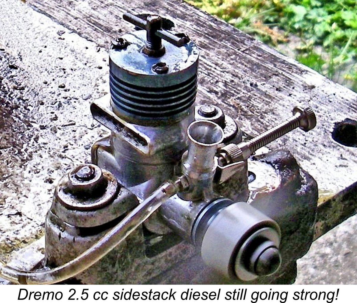
Those bypass constrictions could easily be eliminated by creating a downward extension of each bypass passage in the lower crankcase casting - there's plenty of metal to accommodate this. If such a modification were made, I could easily see the mystery engine's peaking speed being increased by as much as 1000 RPM with a consequent improvement in its already quite impressive peak output. However, I'm leaving well alone - I have no plans to fly this engine, besides which a unit of this rarity and technical interest should be preserved as-is. In any case, its performance as it stands really isn't half bad! The engine came through its testing with flying colours, showing no signs of any mechanical distress at any time. I was careful to keep checking the integrity of the composite piston assembly as the testing proceeded, both All in all, a very satisfactory test! This fascinating engine is a credit to its designer and manufacturer Hans Drenkhahn! As a post-script to this test, I decided that something should be done to deal with the "soft" compression seal in the engine as tested. Accordingly, I sent it along to my valued mate Peter Valicek of the Netherlands. Peter did his usual masterful job of reboring the cylinder and making a closely-fitted replacement piston shell. While he was at it, he also renewed the color anodizing on the cooling jacket and prop driver. As if this wasn't enough, he also made a new replica needle valve assembly copied from another all-original Drenkhahn diesel of roughly the same vintage. The engine is now in as-new condition thanks to Peter's efforts - very much appreciated, mate!! I haven't yet had a chance to complete its break-in and give it another test, but I hope to do so in the future. Hans Drenkhahn's Later Years As stated earlier, the subject engine was probably one of Hans Drenkhahn's earlier efforts following his establishment of the Dremo marque. It seems to have been produced in very small numbers, possibly being more of an experimental model than anything else. It's certainly true that Drenkhahn soon moved on to revised 2.5 cc models - as far as I can ascertain, this was the only sidestack unit using this style of cylinder porting that he produced.
In an earlier section of this article I raised the possibility that the sidestack model which forms our main subject was abandoned early on as a result of Hans Drenkhahn noting the bypass bottleneck in that design and considering alternative approaches to the elimination of that bottleneck. One such approach was clearly to re-orient the cylinder to bring the exhaust to the rear, allowing the creation of far larger bypass passages at the sides. Hence the rear exhaust ball-race model illustrated here may well represent a further development of the sidestack model with the cylinder rotated through 90 degrees. It's notable that it shares the same large-diameter crankshaft, upper cylinder assembly and FRV induction.
Drenkhahn continued his efforts through the 1960's, 1970's and 1980's. During that time he produced a remarkable range of different products, albeit most of them in relatively small numbers by world standards. His ownership of a high-grade cylindrical grinding machine, for which he made an internal grinding spindle for finishing cylinder bores, helped his production efforts considerably. During these very productive years, Hans developed some 40 or more individual designs, ranging from 0.5 cc diesels through 2.5 cc piped glow-plug speed engines all the way up to 15 cc glow-plug units for model boat racing. A number of his designs were made available with R/C throttles, including the unusually-styled 3.5 cc diesel model which appeared in 1985. His largest-ever offering was a 17.25 cc R/C glow-plug aero unit.
As time went by, it became increasingly difficult for Drenkhahn to compete with the products from Russia and elsewhere which were becoming increasingly available on the East German market. Many of these products, notably those from Russia, were of far lesser quality but undercut Drenkhahn's prices significantly. Any marketplace in which price outweighs quality in terms of sales is doomed to lose its quality manufacturers - Britain is a notable example of a country which suffered greatly from this syndrome. Despite developing a fairly significant export market for its products, the Zeiss Jena company was also affected by this trend, hence wishing to divest themselves of their model engine production activities in the late 1960's. They actually explored the possibility of Hans Drenkhahn taking over this role, but he stuck with his own designs. By the time that the re-unification of Germany (die Wende) was formalized in October 1990, the Drenkhahn family operation had shrunk to only three employees - Hans Drenkhahn, his son Manfred and his daughter Kerstin. Unfortunately, the major changes in the economic picture stemming from the re-unification process created significant problems for the Drenkhahns. The monthly rent on the premises increased eight-fold more or less overnight, while the competition presented by engines from Russia and other countries increased dramatically due to the ready availabiliy of these engines. To set this issue in context, a typical Russian engine could be bought in Germany for the price of two quality ball bearings! Material costs also increased significantly. Finally, Hans now found it impossible to find a contractor who could carry out the cylinder liner plating process to an adequate standard. All of these factors forced Hans into disposing of much of his machinery and moving into smaller premises. His children Manfred and Kerstin were forced to find work elsewhere, leaving Hans (now 61 years old) as a small-scale solo manufacturer. Hans himself had to supplement his income from model engines by taking Even then, Hans did not give up. By now he was the sole surviving commercial series manufacturer of model engines in Germany, having outlasted such famous names as Webra and Taifun. It's abundantly clear that he was motivated all along by a genuine and deep-rooted love of model engines rather than by any ambitions of merely making money. He continued to produce very small numbers of his established models as well as entering the replica field in a small way. He also developed a line of very small-displacement "micro diesels", mainly with an eye on the American market. Then in April 1994, disaster struck! The building in which Hans's small workshop was located was sold to overseas investors for conversion into a block of flats (apartments). Hans was forced to move out immediately. Lacking access to new premises on such short notice, he had to dispose of much of his remaining equipment, moving what he was able to retain into a small basement workshop in his home. There he continued his efforts to produce extremely limited numbers of high-quality model engines, continuing up to his somewhat untimely death in 1997 at the age of 68. Conclusion
I hope that this article has done something to pay a long-overdue tribute to one of the world's most talented and dedicated model engine designers and manufacturers. Hans Drenkhahn undoubtedly deserves to be placed right up there with Gordon Burford, Ken Bedford, Gig Eifflaender, Basil Miles, George Fletcher, Gordon Cornell and Alan Allbon (among others) as one of the truly inspirational members of the model engine designing and manufacturing community. ___________________________ Article © Adrian C. Duncan, Coquitlam, British Columbia, Canada First published December 2017
|
||
 This article represents the culmination of a lengthy and wide-ranging search for information stemming from the fact that when I first received the subject 2.5 cc diesel from my good friend Tim Dannels in July 2017, I couldn't put a name to it! The unidentified engine had come to Tim in connection with his involvement in the selling off of the estate of the late Doug Wendt of Montana, USA.
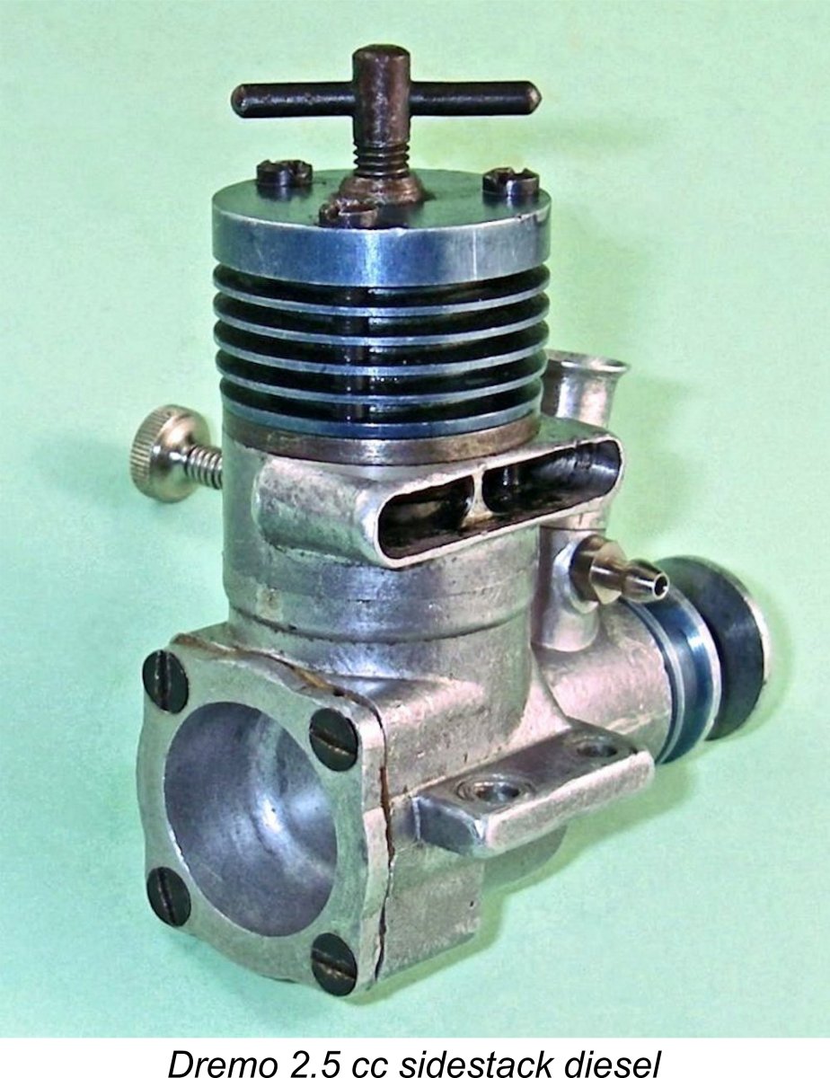
 However, the potential connection with Drenkhahn did not lie down or go away! While I was pursuing the Polish line of inquiry, my valued friend Derek Butler posted a photo of my engine on the widely-read "
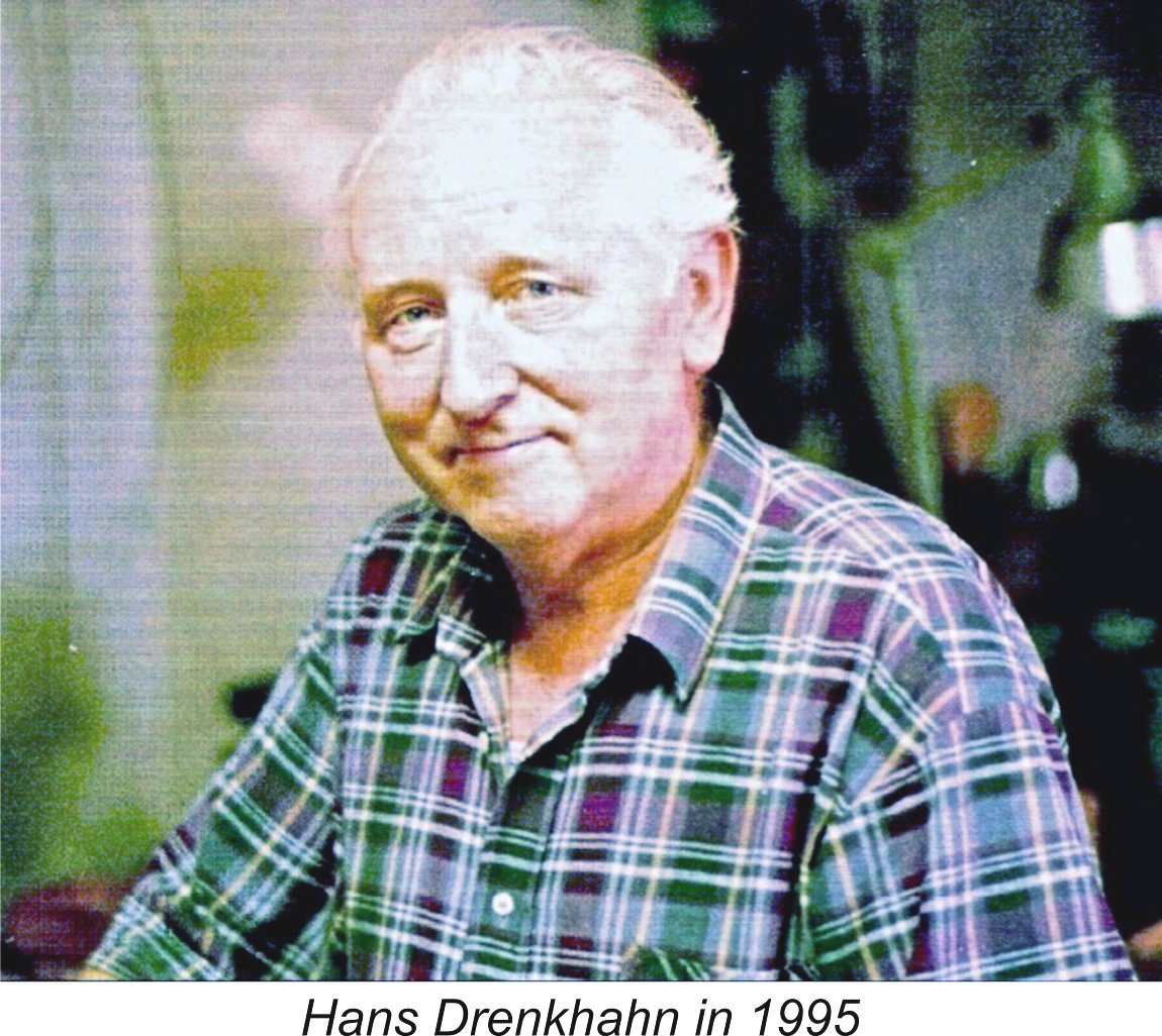 Hans Drenkhahn was born in 1929 in the region which later became East Germany. I have no details of his upbringing and education, but Klaus Hammerschmidt tells us that he began his lifelong involvement with precision engineering in the early post-WW2 period, working as a turner at the former Heinkel aircraft factory at Rostock, an industrial port city located on the Baltic coast of northern Germany in what was then the Eastern Zone. It was during his time at Rostock that Hans first encountered the world of model aero engines, quickly becoming captivated by them.
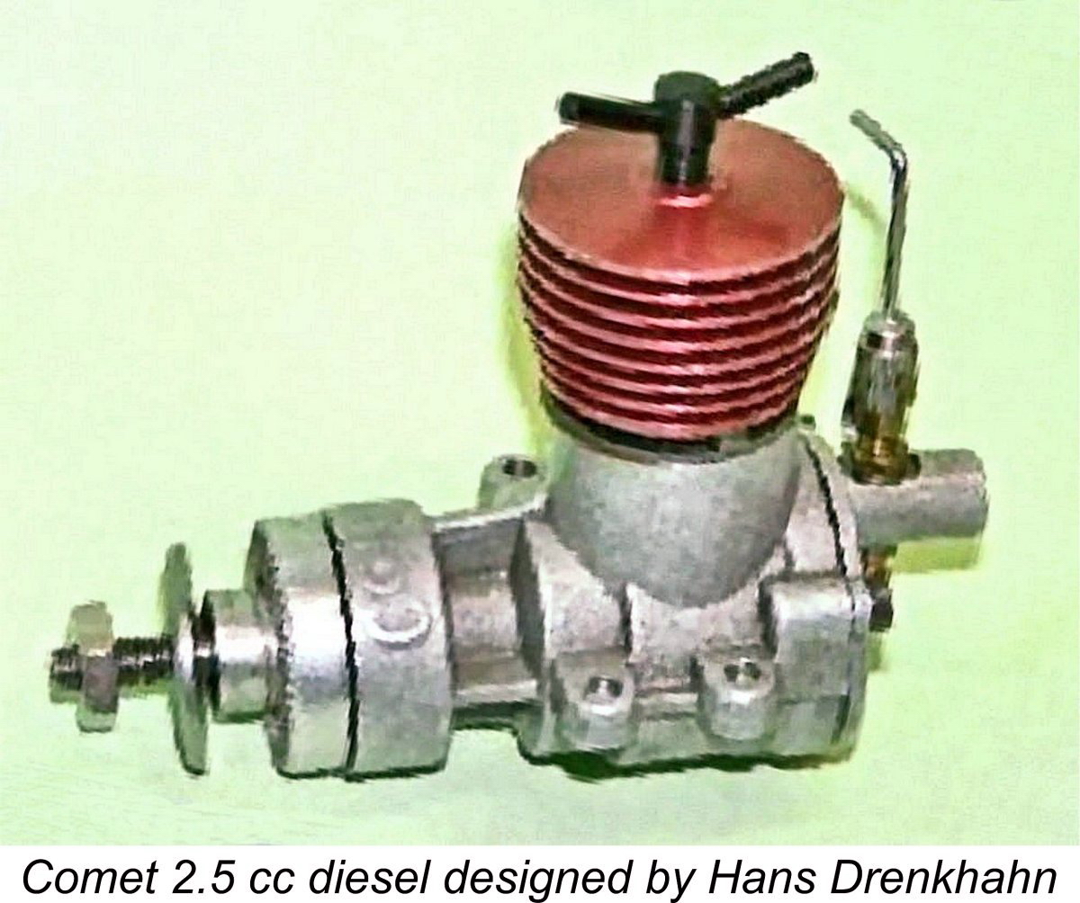 renkhahn next designed a 2.5 cc twin ball-race rear induction radially-ported diesel called the Comet. Lacking the equipment and resources to manufacture this design himself in commercial quantities, he was successful in persuading a Berlin-based elevator (lift) manufacturer called VEB Berliner Aufzugbau to add the manufacture of the Comet engines to their existing portfolio. The term VEB stands for
 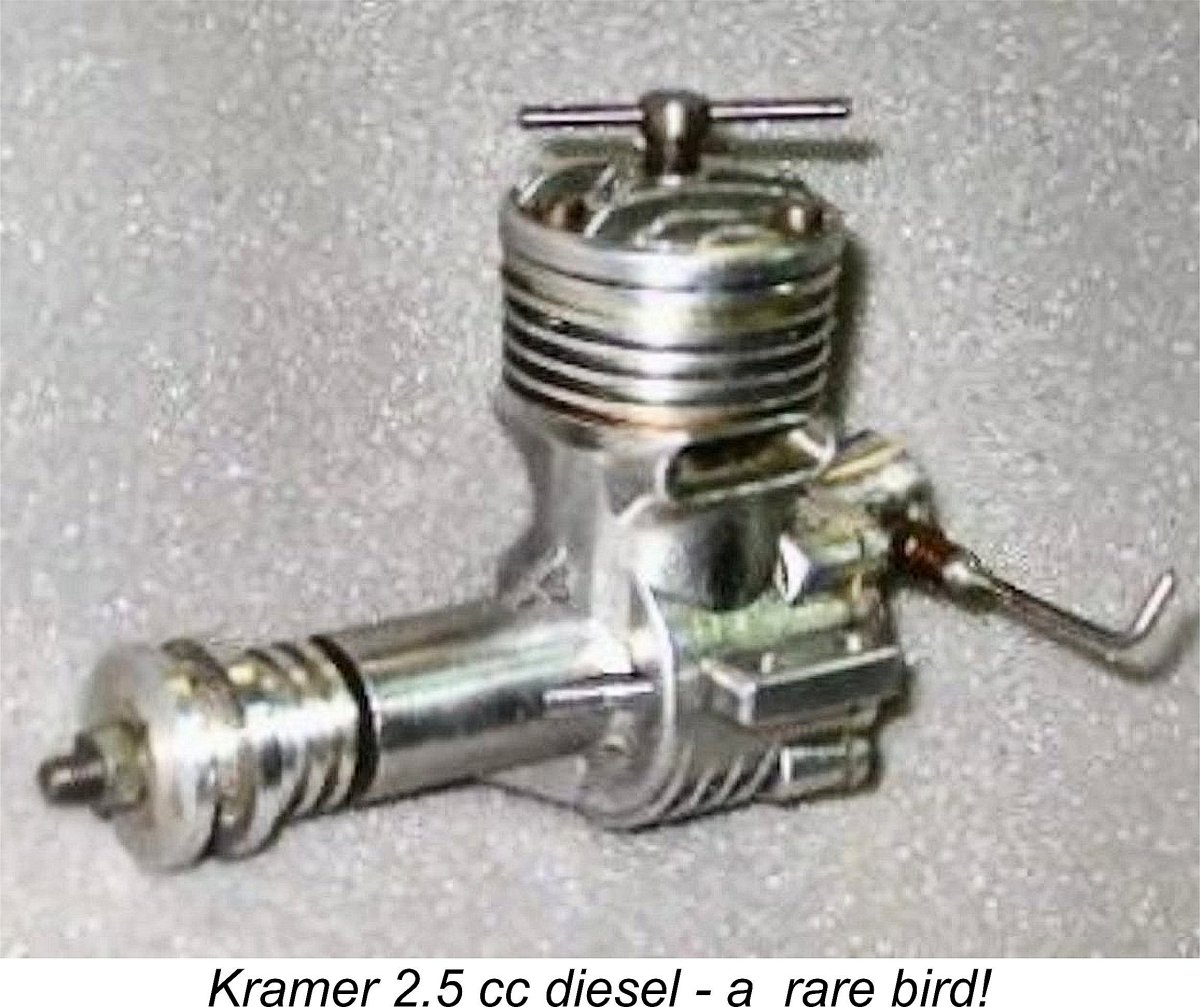 This situation must have been extremely difficult for Hans Drenkhahn to accept, since his own personal standards of precision engineering were very high. In 1955 he sought relief by joining forces with a fellow enthusiast named Krämer to develop another rear induction twin-stack 2.5 cc diesel designated the Krämer Tornado. A small handful of examples were constructed by Krämer, but the project died after the manufacture of only some ten units. Needless to say, the Krämer 2.5 is a rare bird indeed today!
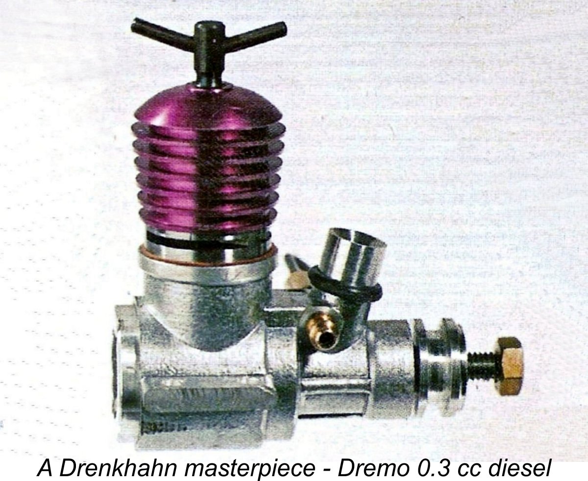
 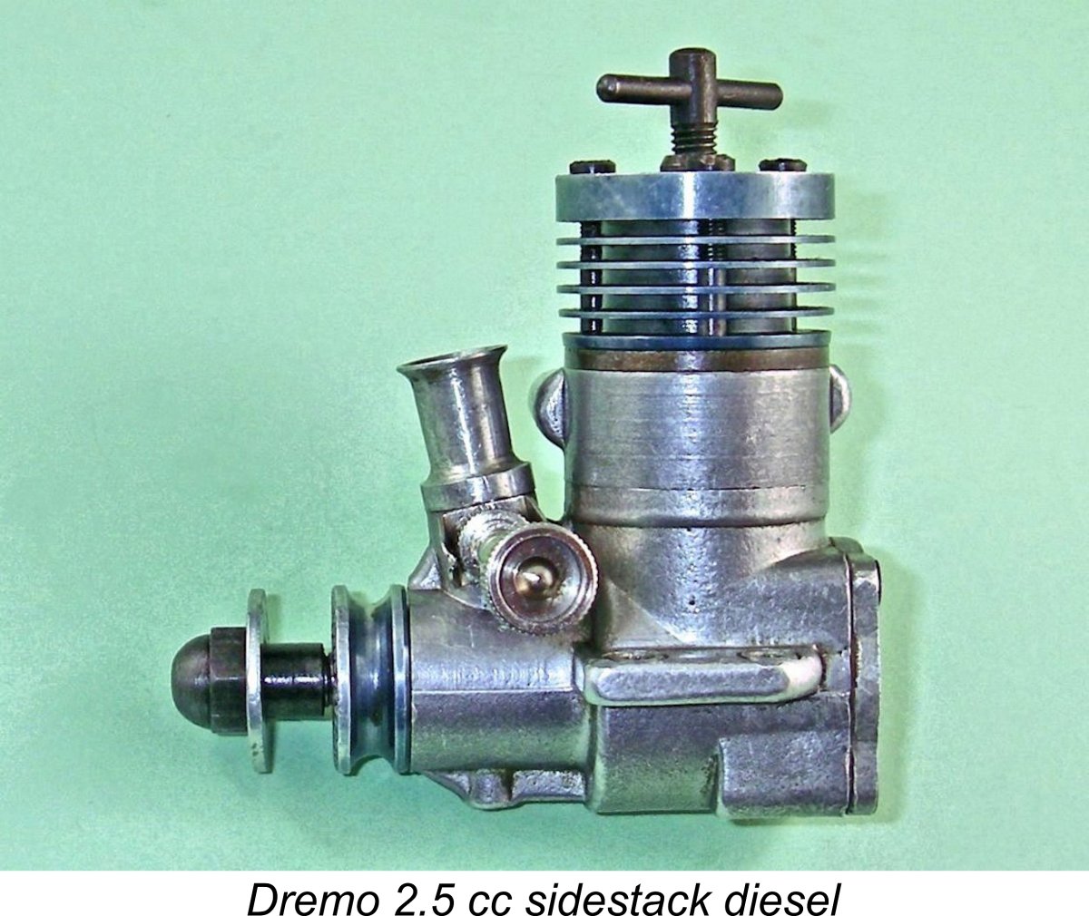 The use of colour anodizing on the subject example of Hans Drenkhahn's work is apparently an unusual refinement for a small East German company at the time in question. Drenkhahn must have pulled a few strings to gain access to this technology, perhaps slipping a few components into a larger batch instigated by others. Hans Tegtmeier tells us that the same blue dye was used by the Russians to produce the black finish which is seen on so many of their classic consumer-grade engines. The black effect was achieved through the use of extremely lengthy blue-dye treatments.
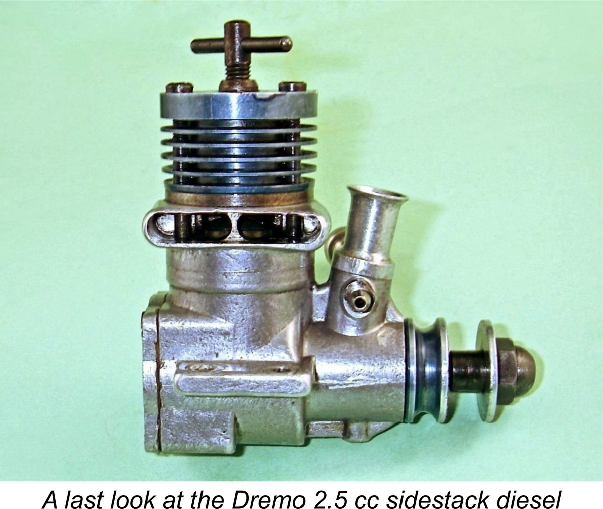
 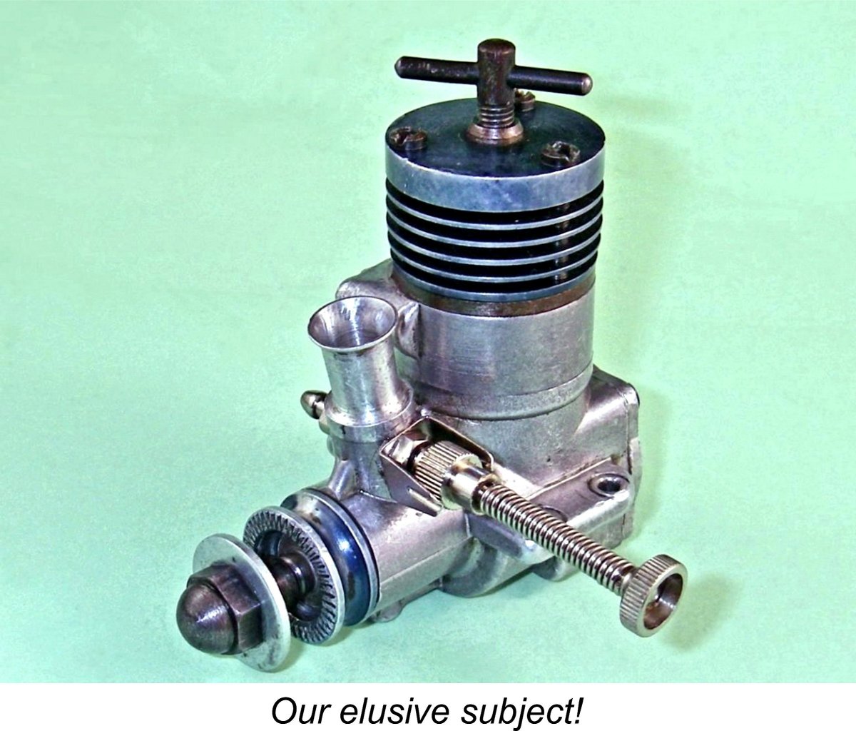 This particular member of the Dremo 2.5 cc diesel series is a 2.44 cc plain bearing crankshaft front rotary valve (FRV) diesel featuring cross-flow loop scavenging through a sidestack exhaust. Checked bore and stroke are 14.90 mm (0.587 in.) and 14.00 mm (0.551 in.) respectively for a displacement of 2.441 cc (0.149 cuin.). The engine weighs in at a healthy 174 gm (6.14 ounces), although I must emphasize that this includes my own steel prop mounting sleeve nut and washer which were made to replace missing originals. I have no idea whether or not they match those originals - they just look right and do the job.
 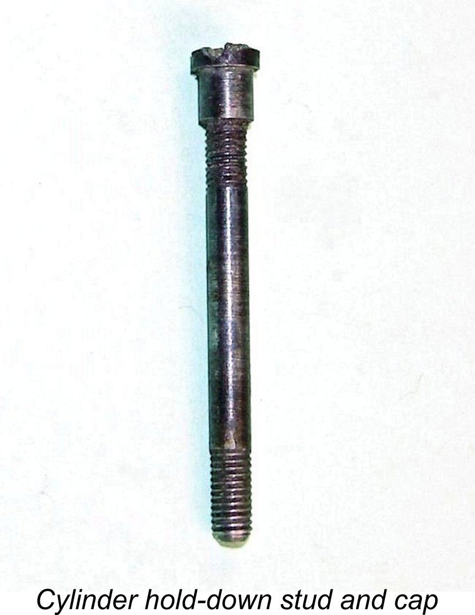 Speaking of which, one of the first points of interest relates to the cylinder retaining fasteners. They are actually not bolts at all – rather, they are steel studs which are threaded M3x0.5 at both ends. What appears to be the head of each retaining fastener is actually a separate female-threaded slot-head cap which engages with the male upper threads on the studs. The upper cooling jacket holes are drilled oversize to match the caps.
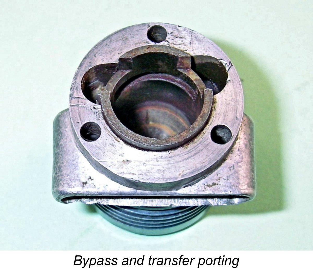 It is the manner in which this transfer port is supplied with mixture that constitutes one of the really intriguing aspects of this engine’s design. The two milled bypass passages mentioned earlier feed into the transfer port from the ends rather than in the middle in the conventional cross-flow loop scavenging arrangement. This design precisely mirrors the arrangement introduced in late 1956 in the then-revolutionary 2.5 cc
 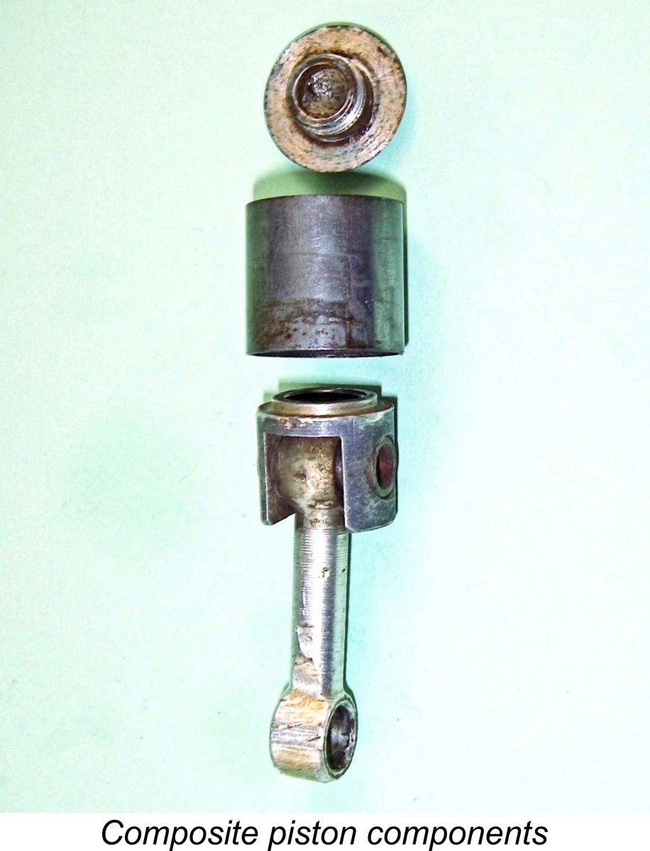 Turning now to the piston, we once again run into a unique design feature. The piston is a composite component consisting of three elements. The working piston is a thin-walled steel shell with no bosses for the gudgeon (wrist) pin. It has a thin and relatively narrow internal flange at the top. The 6 mm dia. hollow steel gudgeon pin fits inside this shell, being located in an aluminium alloy carrier which is inserted into the piston shell to butt against the lower surface of the flange at the top.
 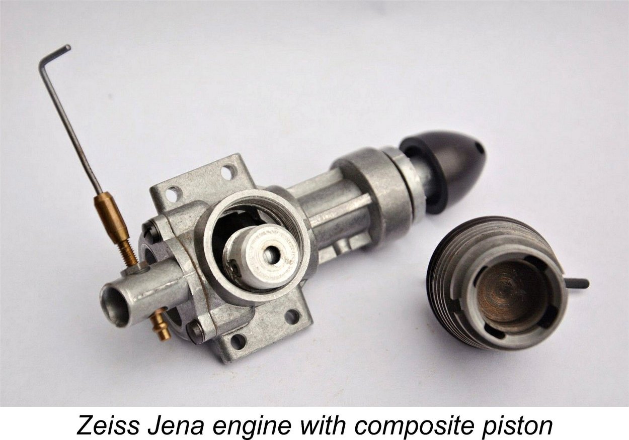 According to Hans Tegtmeier, this style of composite piston construction was also tried by the Carl Zeiss company of Jena, East Germany, makers of the famous
 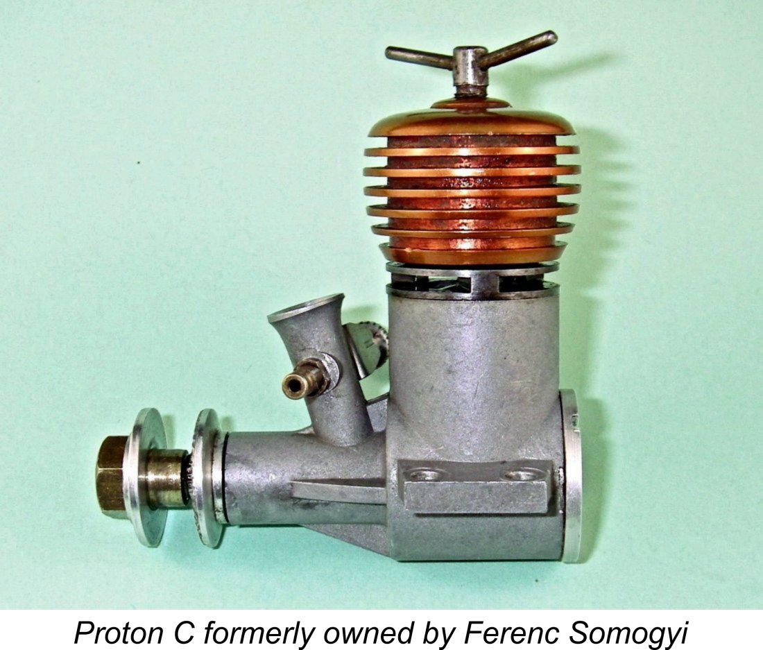 At first glance the assembly used in the Dremo 2.5 would appear to hold considerably greater potential for working loose during operation. However, several factors militate against this possibility. For one thing, the large outside diameter of the alloy components would create considerable frictional resistance to turning of either the carrier or upper plug against the installation flange. For another, any lateral thermal expansion of the aluminium alloy carrier would tend to further tighten the already-snug fit of its installation spigot in the centre of the installation flange. Finally, the internal carrier is exposed at all times to cool incoming mixture in the crankcase. This will result in its running considerably cooler than the upper plug which forms the piston crown, accordingly being exposed to the full heat of the combustion process. Hence the effect of operating the engine will be to expand the hot upper plug against the female thread in the cooler con-rod carrier, most likely stabilizing the threaded joint very securely.
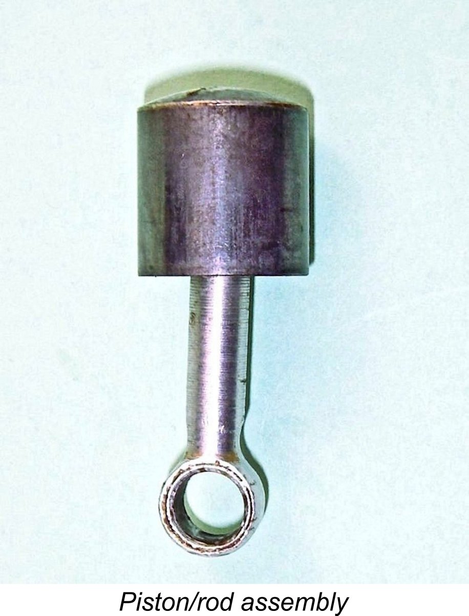 Looking again at the cylinder, we find that the underside of the contra piston is similarly domed in a concave sense. The height of the concave dome in the underside of the contra piston is somewhat deeper than the height of the dome on the top of the composite piston. This will create a rudimentary degree of squish-induced swirl when the engine is running.
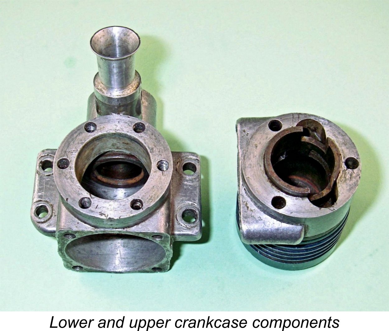 Arriving at the main crankcase at long last, we find a few more points of interest. First, while the casting seems sound enough with no visible porosity, it is not without a flaw. Note the incomplete left-hand mounting lug which evidently resulted from the metal solidifying before the die was completely filled. I always doubted very much that any self-respecting home constructor would have let that pass - having taken the trouble to make a die, he'd simply have cast another case.
 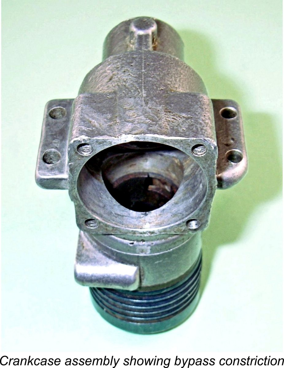 The dimensions of this slot are 1.35 mm wide (the thickness of the lower cylinder wall) by approximately 6.5 mm annular length. Each annular slot formed in this way has an area of roughly 9 mm
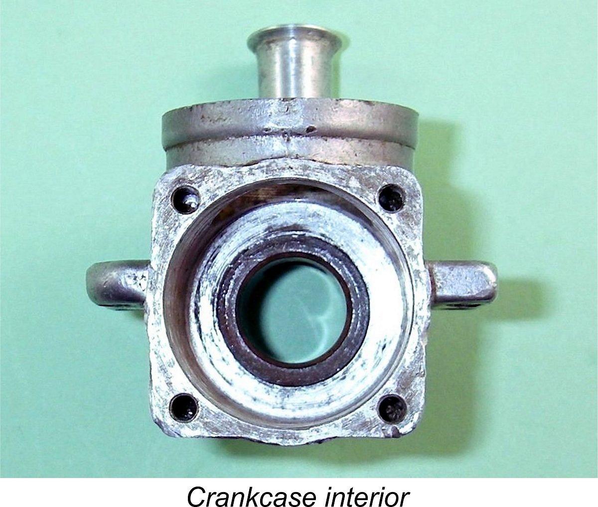 Taking a further look at the main crankcase casting, we find that the integrally-cast main bearing section has a bronze bushing inserted in it. This bushing has a rectangular induction window cut through it which registers with the base of the circular intake tract in the main casting. This design will increase the rapidity with which the induction system opens and closes.
 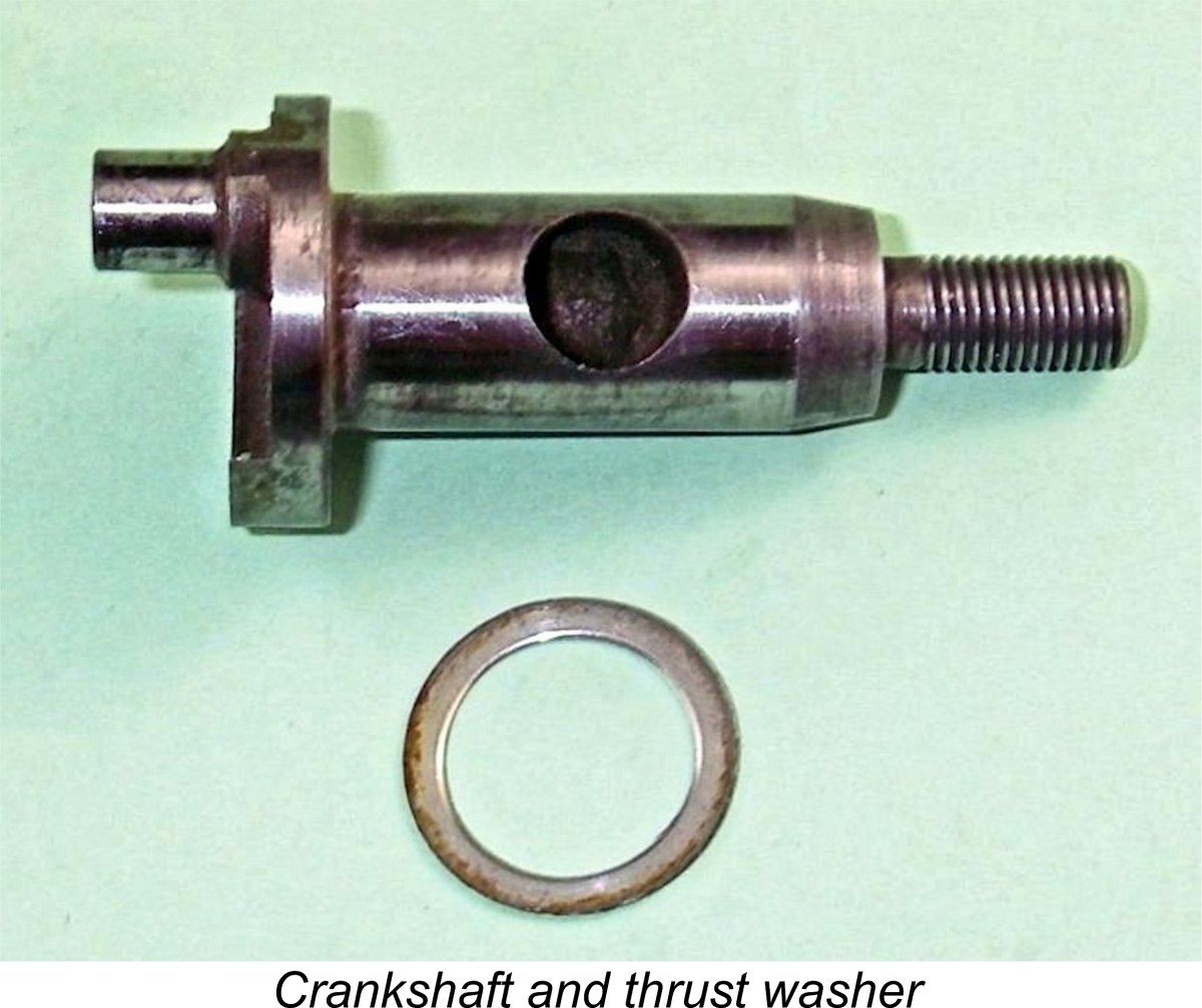 The very well-made and finely finished crankshaft is more or less conventional apart from its unusually large main journal diameter. It is a truly superb fit in its bronze bushing. The very high quality of the surface finishes on the journal and crankpin suggest the possession of high-class grinding equipment along with a good knowledge of how to use such equipment to best advantage.
 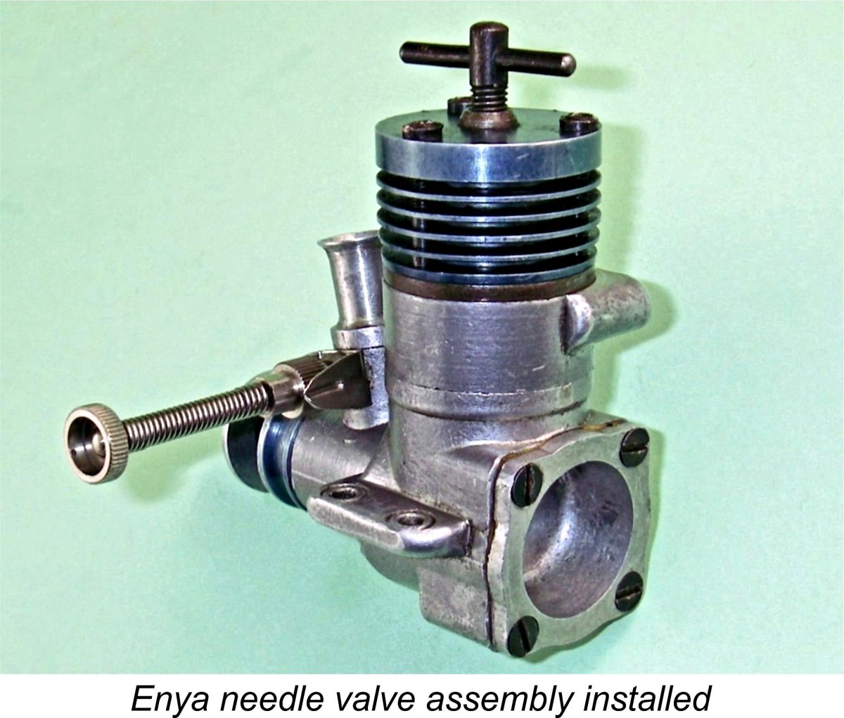 In addition to the prop nut, the engine was also missing its needle valve assembly as received. The needle valve installation hole is 4 mm in diameter, which exactly matches a standard Enya spraybar. Moreover, the jet on an Enya item aligns very precisely with the axial centre line of the intake, making that assembly a perfect match. Accordingly, I fitted an Enya assembly to the engine, while recognizing that there’s no evidence whatsoever that this assembly is anywhere near correct.
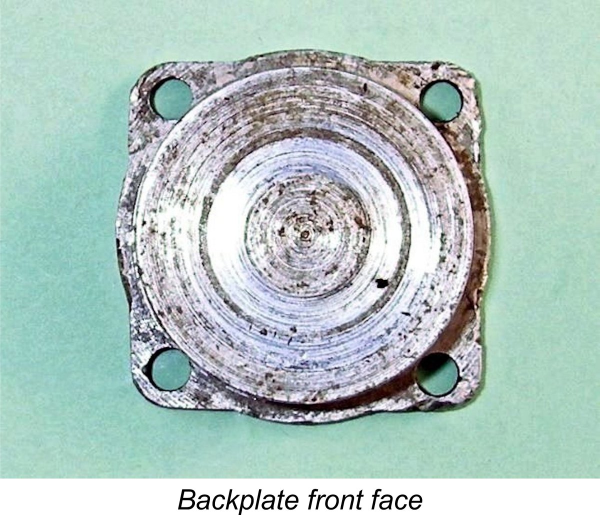 The final component to be described is the backplate. This is another gravity die-casting in light alloy. It has a small protrusion at one edge of its internal recess between two of the mounting holes, which normally indicates an internal shelf to provide piston skirt clearance. However, there’s no such shelf in this instance – the internal installation spigot is a perfect cylinder. It appears that the manufacturer may have contemplated the use of this casting in a different design which did require such clearance.
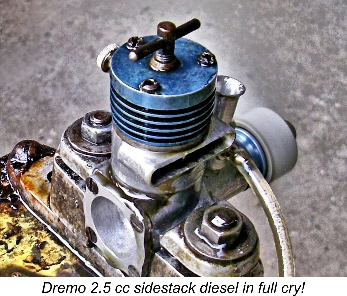 Once in the test stand with the 10x6 prop fitted, it became immediately apparent that the piston/cylinder fit was definitely on the "soft" side as a result of the seemingly considerable amount of use which the engine had clearly received from previous owners. Accordingly, I used an oily fuel containing 30% castor oil to help the seal during operation. I also added a small oil prime to the exhaust prime which the engine turned out to prefer for starting. Subsequently starts demonstrated that this latter refinement was not absolutely necessary, although it did help starting to some extent.
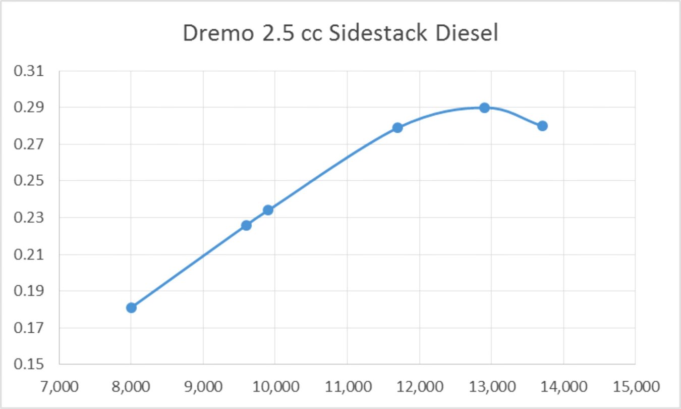
 Obviously, both the Enya and the MVVS developed their peak outputs at significantly higher RPM than the test example of the Dremo 2.5, which clearly develops superior mid-range torque to either of the other units. I have no doubt at all that the difference in peaking speeds is largely down to the two previously-noted constrictions in the bypass passages of the test unit, which seem to cause the engine to begin running out of breath above 13,000 RPM. Friction losses from the very large main crankshaft jounal doubtless also made a contribution.
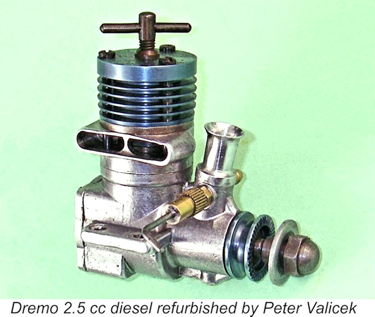
 A noteworthy design in the context of this study was the illustrated rear exhaust twin ball-race diesel model. This was clearly a direct descendant of the blue-topped design described earlier. It has a single exhaust port located at the rear together with two opposing bypass passages at the sides of the crankcase. These two bypass passages supply a pair of generously-sized transfer ports a la MVVS RL) located towards the front.
 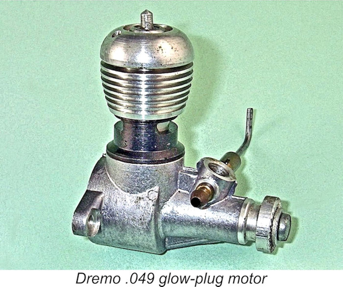 Although he had cut his designing teeth on diesels, Drenkhahn soon moved into the development of glow-plug units, of which he produced a good variety over the years. The neat little .049 glow-plug unit illustrated here is a typical example. Much of the work was carried out in-house, but certain specialist processes such as plating, anodizing and heat treatment were contracted out to small specialist companies.
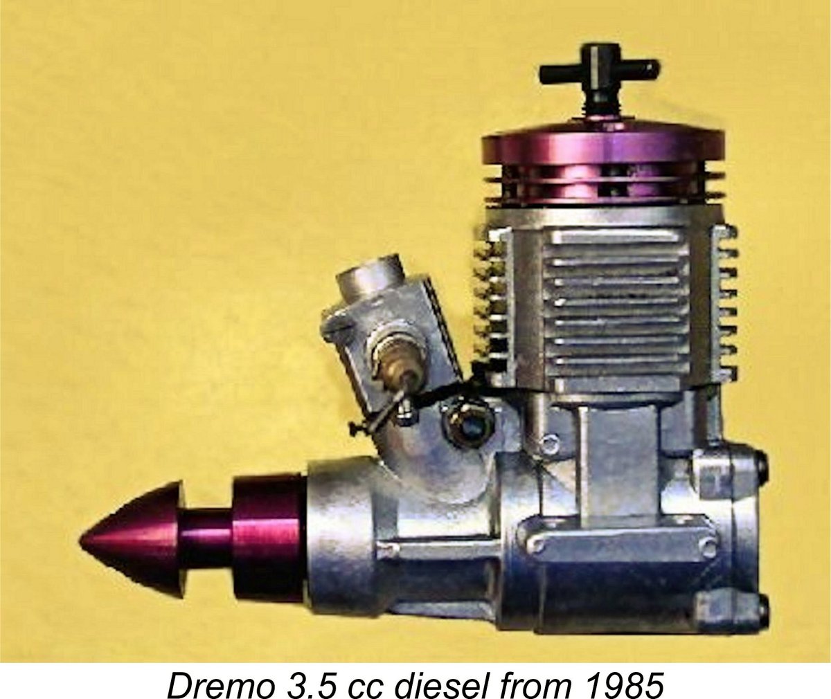
 It took a while to finally come up with a secure identification of this very intriguing engine, but I for one feel that the effort was well worth it. The Dremo 2.5 cc sidestack diesel represents a generally successful initial exploration by Hans Drenkhahn of the gas flow concepts first introduced in late 1956 by Enya and later refined by MVVS with their 1958 25D model. Based upon the foregoing review, the engine must be judged a noteworthy success, with considerable potential for further development.
 | |