
|
|
A Tale of Tuned Nordecs
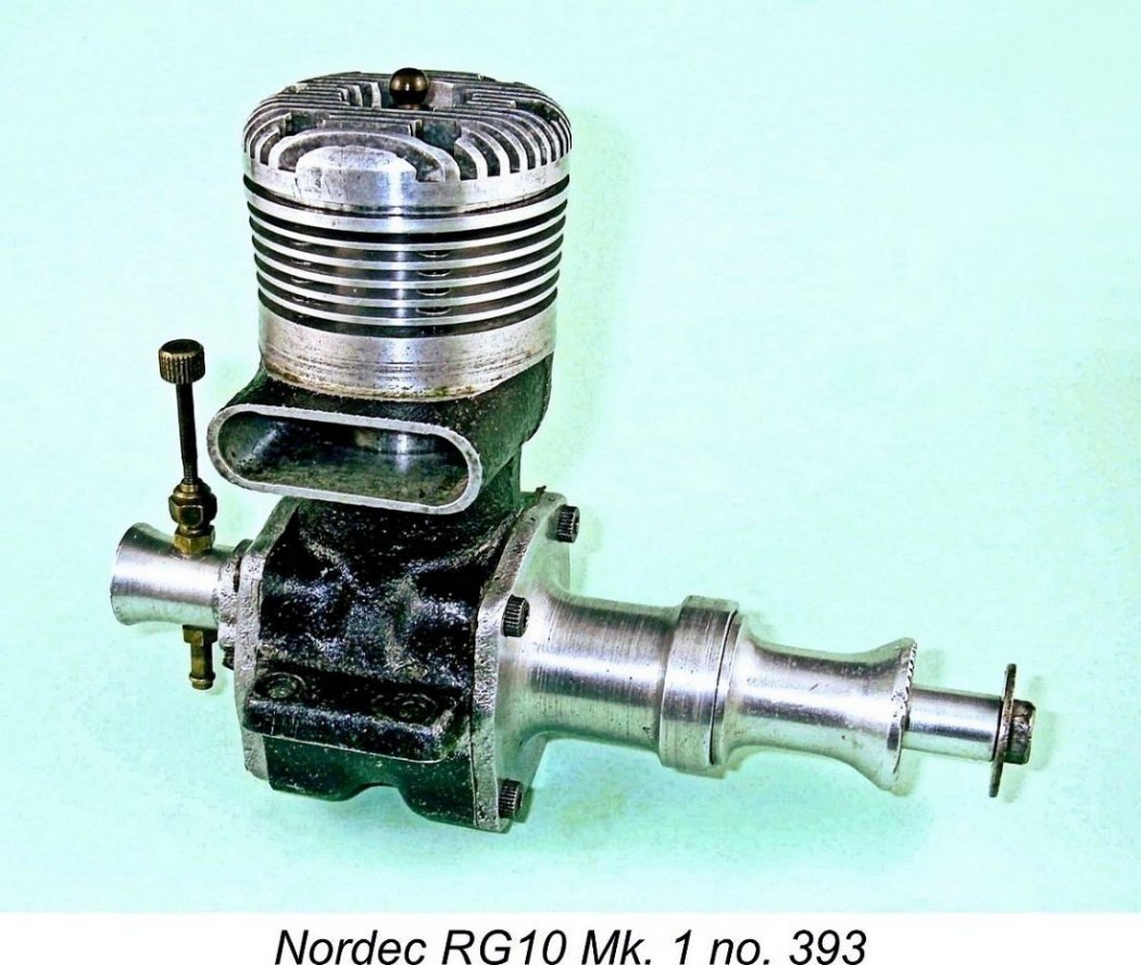
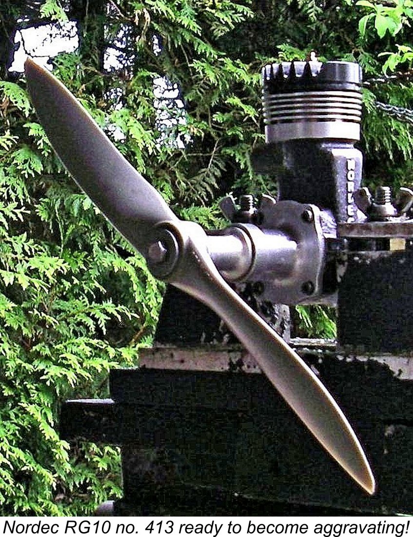
Having read the earlier article, you’ll be aware that the stock RG10 glow-plug version of the Mark 1 Nordec racing engine which appeared in mid 1948 fell somewhat short of achieving a true “racing” performance, even by the standards of its day. The article mentions the efforts of expert tuners like Fred Carter of Great Britain and Zdeněk Husička of Czechoslovakia (as Czechia was then) to extract more performance from the Nordec. While the stock Nordec RG10 was good for perhaps 100 mph (160 km/hr) in a control-line speed model under ideal conditions, Carter was able to achieve fairly consistent speeds in the 116 mph (187 km/hr) range with his Nordec-powered “Little Rocket”. Husička did even better than this - he actually managed an official speed of Of course, the standard Nordec’s performance shortcomings were as obvious to others as they were to Carter and Husička. Most of these individuals would have lacked the equipment and expertise to go as far as Carter by making a new piston and head along with a replacement front end and venturi. However, they did have such tools as hand files, rotary files, grinders and drill presses. This allowed the more knowledgeable individuals to deal quite effectively with a number of the obvious shortcomings in the engine’s design as delivered. Quite a few years ago now, I was fortunate enough to acquire a modified example of the Mk. 1 Nordec RG10 glow-plug model which was in very nice condition despite having clearly been mounted in at least one model and having seen a fair bit of hard use. This is In all probability this is because their performance shortcomings as delivered together with their very significant weight and high fuel consumption likely became all too obvious during the initial bench-testing phase, apparently giving them a reputation as overweight under-performers with an expensive thirst. However, they were rather too big to simply “lose”, as well as being extremely well made. This evidently resulted in many of them being put away in the attic, not to re-emerge until the latter-day “collector” era was well and truly underway. Despite the challenges involved, a few hardy souls appear to have persisted in trying to get these engines to perform at a more acceptable level. There weren’t too many Fred Carters out there, but there were a few individuals who possessed enough engine know-how to recognize the performance-limiting elements of the Nordec’s design and to make a rational attempt to deal with at least some of those issues. It turned out that my acquisition - Nordec RG10 no. 413 - had clearly been owned by just such an individual. It was obvious all along that it had been fitted with a head from the later Nordec Special - indeed, at first sight one would take it to be a Special. However, the serial number confirms that it started out life as a standard Nordec RG10 Mk. I.
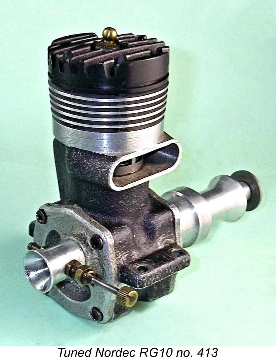
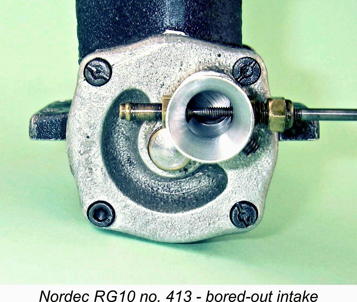
Here was a chance too good to pass up! I’d often wondered how much better one of these engines could be made to run using standard home tuning techniques. With a single exception (to be noted later), the unknown tuner had done pretty much everything that I myself would have done if I had been undertaking a Nordec tune-up. What could be more obvious than to put this engine on the bench and compare its performance to that of a stock unit? So that’s exactly what I set out to do! I'm only surprised that it took me so long to get around to doing this! But before getting to the test results, it seems only proper that we should look at the ways in which engine number 413 has been modified from its original condition. Furthermore, in order to understand these modifications it’s necessary to appreciate the shortcomings in the engine’s design which they were intended to address. So let’s get right to it!! Design Shortcomings and the Tuner’s Responses One look at Nordec RG10 no. 413 is enough to confirm that the engine has been modified by having a Nordec Special head fitted along with a very neatly-executed shortening of the exhaust stack. The latter was a pretty standard modification among racing engines, generally aimed at making the engine a better fit in the model for which it was intended. A closer external examination reveals that the throat diameter of the intake venturi has been opened out as well.
An indication of the care taken by the unknown tuner was the fact that the main bearing housing was marked with an arrow to ensure that it would always be re-installed in the same orientation if the engine was ever dismantled, as racing engines tend to be quite frequently. Apart from these features, the engine remains externally in completely original condition.
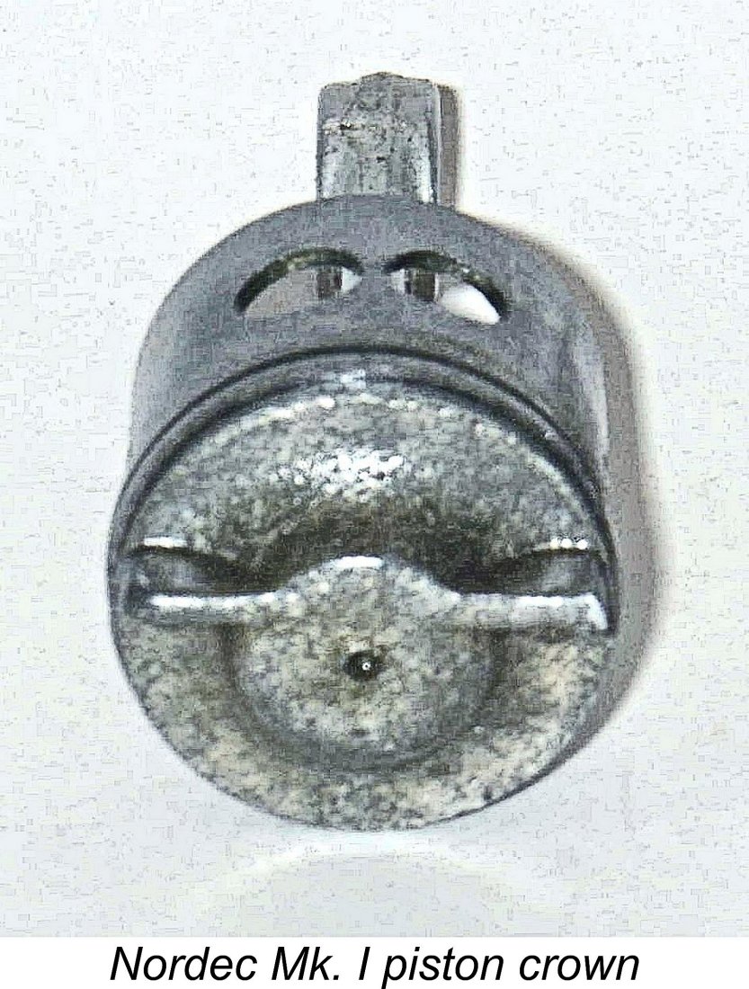
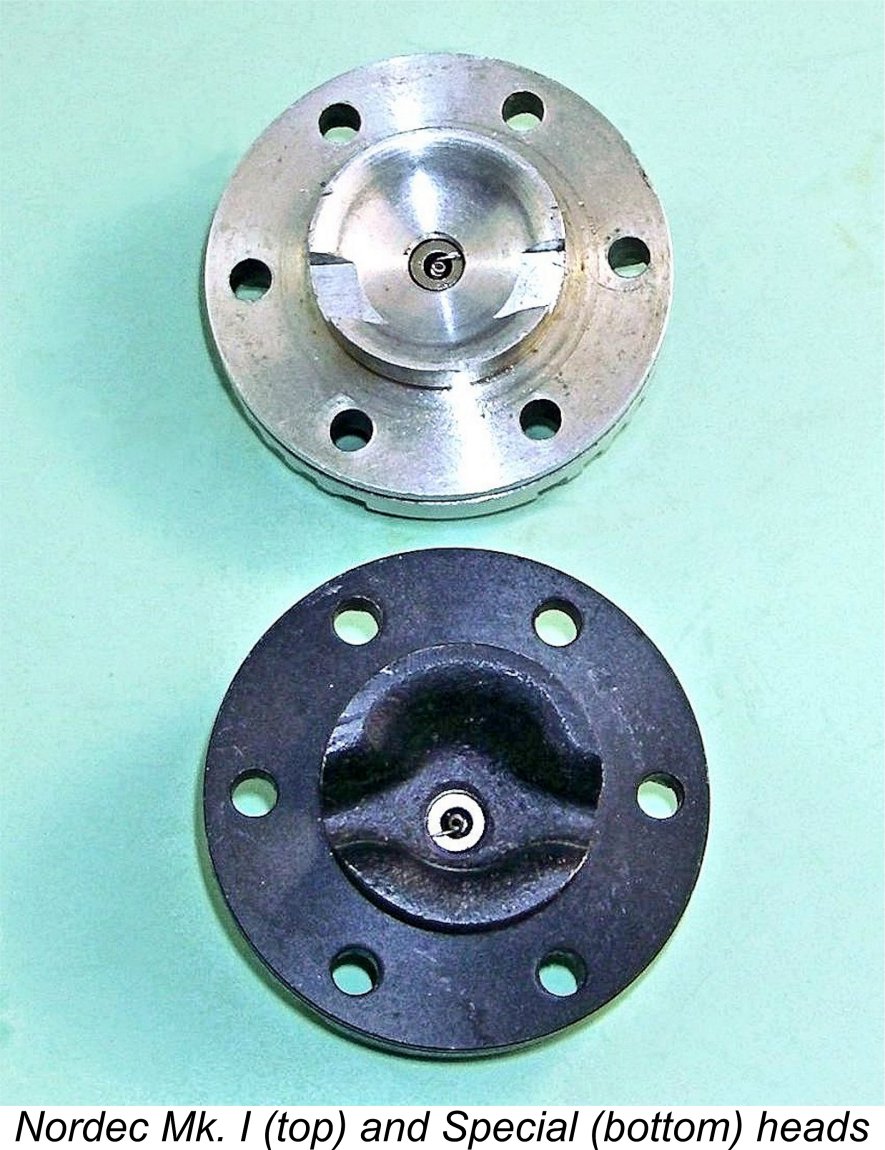
One of the major performance-limiting features of the original Nordec engines was the cylinder head design. The piston crown featured in this original model followed standard then-current racing engine practise by incorporating a central dome with a transverse baffle offset towards the transfer side. In the case of the Nordec, the dome was of lesser height than usual, for reasons which will soon become apparent. Such a piston crown was typically complemented by a cylinder head whose underside contours more or less conformed to those of the crown, imparting some swirl to the mixture during compression and concentrating the fresh charge around the point ignition source at the time of ignition, thus reducing the maximum required flame propagation pathway. Both effects should speed up the full involvement of the fresh charge in the combustion process - an important factor in high-speed operation.
This head conformed only marginally to the piston crown, resulting in an inefficient low-swirl combustion chamber with the fresh charge being widely dispersed at the time of ignition. To make matters worse, the pocket of gas trapped behind the piston baffle at top dead centre was isolated from the centrally-located plug, significantly delaying the involvement of that portion of mixture in the combustion process following ignition.
The result was the late 1949 introduction of a revised McCoy-influenced high-crown piston and sand-cast head incorporating a far more efficient combustion chamber shape. However, the resulting Nordec Special Series I came too late to save the Nordec range - only around 250 examples appear to have been manufactured before the company ceased model engine manufacture in mid 1950. The subject modified Nordec RG10 no. 413 has a Special head fitted but retains the standard Mk. I piston. I read this as an indication that the tuned engine retained its original cylinder head In any case, the Special head actually conforms quite well to the Mk. I piston crown - certainly far better than the original Mk. I head. In addition, although the external glow-plug terminal remains centrally located, the fact that the plug is angled to position the coil directly above the baffle reduces the flame propagation path to initiate the involvement of the mixture behind the baffle in the combustion process. The engine's checked compression ratio with the Special head fitted comes out at a slightly elevated 11 to 1. This is a little less than the 13 to 1 ratio measured for my Nordec Special no. 1137, which naturally has both the Special head and higher-crowned Special piston fitted. Although by no means unprecedented, this was pretty high for glow-plug operation, even on straight methanol/castor fuel. This raises the possibility that the retention of the slightly lower-crowned standard piston in engine no. 413 was a conscious decision based on a desire to reduce the compression ratio to a figure more suitable for glow-plug operation while still enhancing combustion efficiency. Having taken steps to improve the engine’s combustion characteristics, what else was there to do? Obviously, since our more efficient combustion chamber should have the potential to burn more fuel with greater efficiency, we need to stuff more fresh mixture into said combustion chamber! In this context, another factor which clearly limited Nordec performance was its limited ability to ingest and transfer sufficient volumes of fuel mixture. It was this area which received the full attention of our unknown tuner. On the ingestion side, the standard Nordec already featured relatively aggressive induction timing. The disc valve opened at 45 degrees after bottom dead centre and closed at 55 degrees after top dead centre for a seemingly adequate total induction period of 190 degrees.
The Nordec could clearly deal with an even larger diameter intake in a racing context, but the amount of metal available precludes this - the tuner did as much as he could using the stock components, also trimming the inner ends of the needle valve carrier and surface jet to match the larger diameter. Overall, this modification would appear to represent a significant enhancement of the engine’s ability to ingest fuel mixture at high speeds. Further enlargement (which would require the re-machining of the backplate to accommodate a larger venturi) would no doubt cause suction to suffer, but in an all-out performance situation this could be dealt with through the provision of pressure feed.
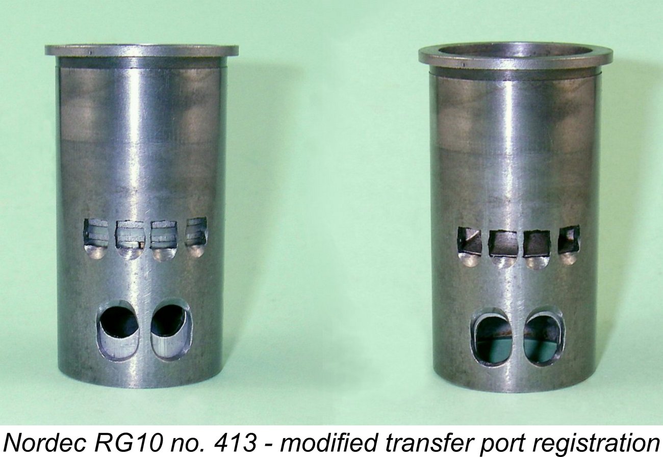
To get around this, our unknown tuner had widened the top of the bypass passage sufficiently that all four of the transfer ports were completely unobscured. This work was done very neatly indeed - whoever did it was clearly very capable. Great care had to be taken to ensure that the widening did not break through the outer surface of the casting, thus irreparably destroying the crankcase seal. Having gone so far, the tuner also created scallops in the outer wall of the cylinder liner below the four transfer openings to direct the incoming fuel mixture more vertically into the cylinder. These can be seen in the images below. Given the relatively low baffle on the standard Nordec piston, this was probably a good idea. The effect of this work was clearly to enhance the ability of the transfer ports to pass mixture from the bypass passage into the cylinder. However, there still remained the obstruction of the rather restrictive bypass passage itself. The opening at the base of this passage was cast relatively narrow, for which reason a pair of piston skirt ports with matching cylinder wall ports opening into the bypass passage were provided to supplement the lower point of entry.
The problem with the Nordec's piston port system was the manner in which the piston skirt ports registered with their counterpart openings in the lower cylinder wall. The design was such that the two sets of circular openings were only in perfect alignment (and thus fully open) at bottom dead centre. This corresponded to the point of maximum volumetric crankcase displacement by the descending piston, since it could descend no further. Ideally, with a free-flowing bypass/transfer system, a significant proportion of the transfer gas movement should already have taken place at this point. Such considerations lead to the immediate conclusion that if the piston skirt ports are to be fully effective they should be completely open well prior to bottom dead centre. In terms of area, the bypass entry system should remain well ahead of the transfer ports at all times during the transfer cycle. To address this deficiency, our tuner extended the cylinder ports upward, maintaining an oval “race-track” form with no sharp edges to create stress concentrations, also externally chamfering the upper edge of the cylinder ports to ease gas flow into the bypass. To complement this modification, he extended the piston skirt The result was that when the four transfer ports began to open, the piston port system was already wide open and only got wider as the piston continued to descend. The image at the left shows the registration of these ports at the points of transfer initiation (L) and maximum opening (R). At all stages of the cycle, overall bypass entry area is substantially greater than the total area of the four transfer openings, thus presenting no limiting constraint upon gas movement from the case to the cylinder. At first sight, a very rational and worthwhile improvement. I have an example of the bulge bypass Hornet 60 from America which has been modified in a very similar manner.
Apart from this, it would appear that the tuner had gone to a good deal of trouble to optimize the fit and alignment of the twin ball-bearing assembly which supports the crankshaft. The engine has by far the most free-running front end of any Nordec of my quite extensive experience. I elected not to disturb this assembly given the care which appeared to have been taken to get it just right. The tuner had also taken particular care with respect to the selection and fitting of the piston rings. This example of the Nordec has the best compression seal of any unit with which I am familiar - any diesel would be flattered by having a seal this good! The result of the above work is an example of the Nordec RG10 which should definitely have a far greater ability to ingest, transfer and burn fuel mixture at high speeds, in addition to having an extremely well-fitted main bearing assembly and a superb compression seal. We would expect a measurable improvement in the performance of this engine over and above a standard unit. Let’s find out just how measurable ….. on to the test bench!! The Nordec on Contemporary Test The original unmodified Nordec RG10 glow-plug model was the subject of two published tests back in the day. The first of these was Lawrence H. Sparey's test which appeared in the March 1949 issue of "Aeromodeller" magazine. Using a straight 3:1 mixture of methanol and castor oil with no added nitro, Sparey reported a rather disappointing peak output of 0.480 BHP @ 11,200 RPM. Although experience in the field quickly confirmed that the Nordec performed at a level well below the 1+ BHP typically developed by then-contemporary competing 10 cc models, Sparey's figures still appear to me to sell the engine somewhat short. Admittedly, his use of a straight fuel doubtless influenced his findings.
Sparey's report on the R10 was far more positive than his review of the RG10. He cited a few handling difficulties, but nonetheless managed to extract a peak output of 0.717 BHP @ 13,250 RPM. Since he was still using straight methanol/castor fuel with no added nitro, it's clear that the engine's potential output was even greater than this. Sparey was at a loss to explain why the spark ignition and glow-plug variants had performed at such different levels using the same straight fuel, stating that he could "only put it down to one of those mechanical anomalies with which all engineers are familiar". In other words, he felt that this was a case of two different examples of the same series-production engine performing at significantly different levels - a not uncommon occurrence. In view of Sparey's puzzlement regarding his results, it's fascinating to note that Peter Chinn had virtually the same experience with the spark ignition and glow-plug variants of the Nordec. Chinn's findings were published in the June 1949 issue of "Model Aircraft". Using a fuel containing an unspecified proportion of nitromethane, Chinn found a peak output of 0.630 BHP @ 12,200 RPM for the RG10 glow-plug model, considerably better than Sparey's figures. Perhaps his use of nitro made all the differerence! However, it's far more significant to report that Chinn also tested the spark ignition R10 model, finding a peak output of 0.74 BHP @ 12,500 RPM on straight methanol/castor fuel. He thus offered solid support for Sparey's findings for the same model. I suspect that the figures reported by Sparey and Chinn for the R10 were probably more representative of the performance to be expected from a good example of the RG10 glow-plug model. Experience shows that the same engine running on glow-plug ignition can generally at least match the performance on spark ignition provided that the plug heat range is well matched to the engine's operating characteristics on the fuel being used. It's almost certain that the importance of plug heat range was very poorly understood at the time of these tests. For me, the issue thus became that of determining whether or not modified Nordec no. 413 could beat the higher figures reported by Chinn and Sparey. Only one way to do this - put the engine into the test stand and give it a few runs! The Tuned Nordec Evaluated
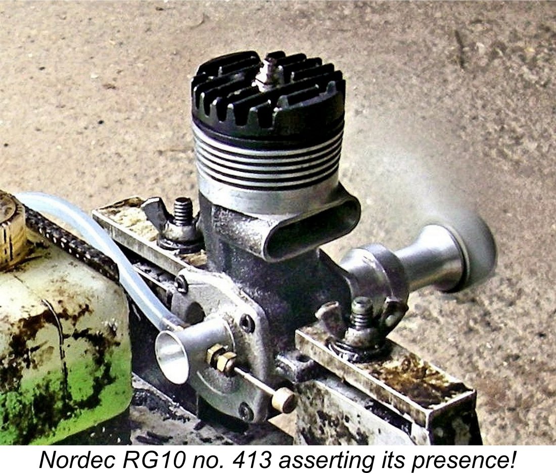
The one thing that made this possible was the fact that the engine was clearly very well run in. Accordingly, I would only have to run it long enough on each prop to get a peak speed reading - probably less than a minute for each airscrew. This being the case, the entire test would probably require a total of only 5 or 6 minutes of running time. To minimise my chances of causing neighbourly friction, I picked a mid-week time period on a rainy day when all of the neighbours would be at work, in school or huddled indoors staying dry!
I didn't intend to do any more running than absolutely necessary for this test, hence confining myself to only those props, which I felt should allow the engine to run at least to its peak and perhaps a little beyond. This approach would allow a direct comparison of the tuned Nordec with its contemporary Rowell competition. I used an oily fuel containing 10% nitro for these tests - the same fuel that I had used in my Rowell test. No doubt the engine would do better on a higher dose of nitro, but few if any British modellers at the time when the Nordecs were on sale would have been able to run even this much nitro in their fuel. The stuff was darn near impossible to get in Britain and prohibitively expensive when you could find a source. So this was probably a typical “racing” fuel of the day for those who could somehow gain access to nitromethane. In recognition of the engine's very high compression ratio, I used a cold plug for this test. Set up in the test stand with the APC 11x6 prop fitted, the engine's 11 to 1 compression ratio was very much in evidence when flicking the engine over with the plug unlit. The compression seal provided by the rings was outstanding. It was obvious that my usual classic racing engine "bounce start" technique would be required to get this one going! This involves setting the prop at "ten past eight" with the piston at bottom dead centre, administering a healthy prime and then HITTING the prop backwards from the bottom dead centre position with the plug activated. The inevitable backfire almost always starts the engine in the correct direction with one's finger well out of the way. Using this method, the Nordec proved to be a one-hit starter practically every time. Once going, response to the needle was extremely positive, making it very easy to establish the optimum setting. Suction seemed to be excellent, with no fuel draw difficulties as the level of fuel in the tank dropped below the needle elevation (which it did remarkably rapidly!). Once set, the Nordec ran extremely smoothly, with no trace of a misfire. The following data were recorded on test.
As can be seen from the power curve, I missed the actual peak. However, an extrapolation of the data by mentally smoothing out the curve clearly implies that the tuned engine developed a peak output of around 1.02 BHP @ 13,200 RPM. This is a very substantial improvement on the figures reported for the stock RG10 by Sparey and Chinn - in fact, it closely approximates the claimed performance of the 1946-48 McCoy 60 Red Head upon which the RG10 was based. It's clear that the efforts of our unknown tuner were very effective in overcoming some of the functional limitations of the standard Nordec design.
However, before we get too excited, it's important to note that this performance still falls a little short of the figures of 1.08 BHP @ 13,300 RPM which I recorded during my earlier test of the competing Rowell 60 Mk. I in standard unmodified form. The tuned Nordec was still a few hundred RPM down on the Rowell on all props. Looking on the bright side, it did meet my previously-stated expectation that it might approach the performance of the Rowell! The modifications described earlier unquestionably brought the RG10 up to a respectable level of performance in comparison with the British opposition as of 1948, but even in tuned form the engine was no threat to win any competition against well-prepared powerplants from other makers, particularly the imports. Still, the tuned Nordec had lost none of the good manners which are typical of the Nordec marque, while performing at a significantly higher level than the stock engine. So full marks to whoever carried out these modifications - they appear to have been very effective! The tuned engine came through its moment in the sun (actually, rain!) with no sign of any mechanical stress. Everything stayed tight and no leaks presented themselves. These units are about as close to bulletproof as a racing engine can get! A Tuned Factory Test Example
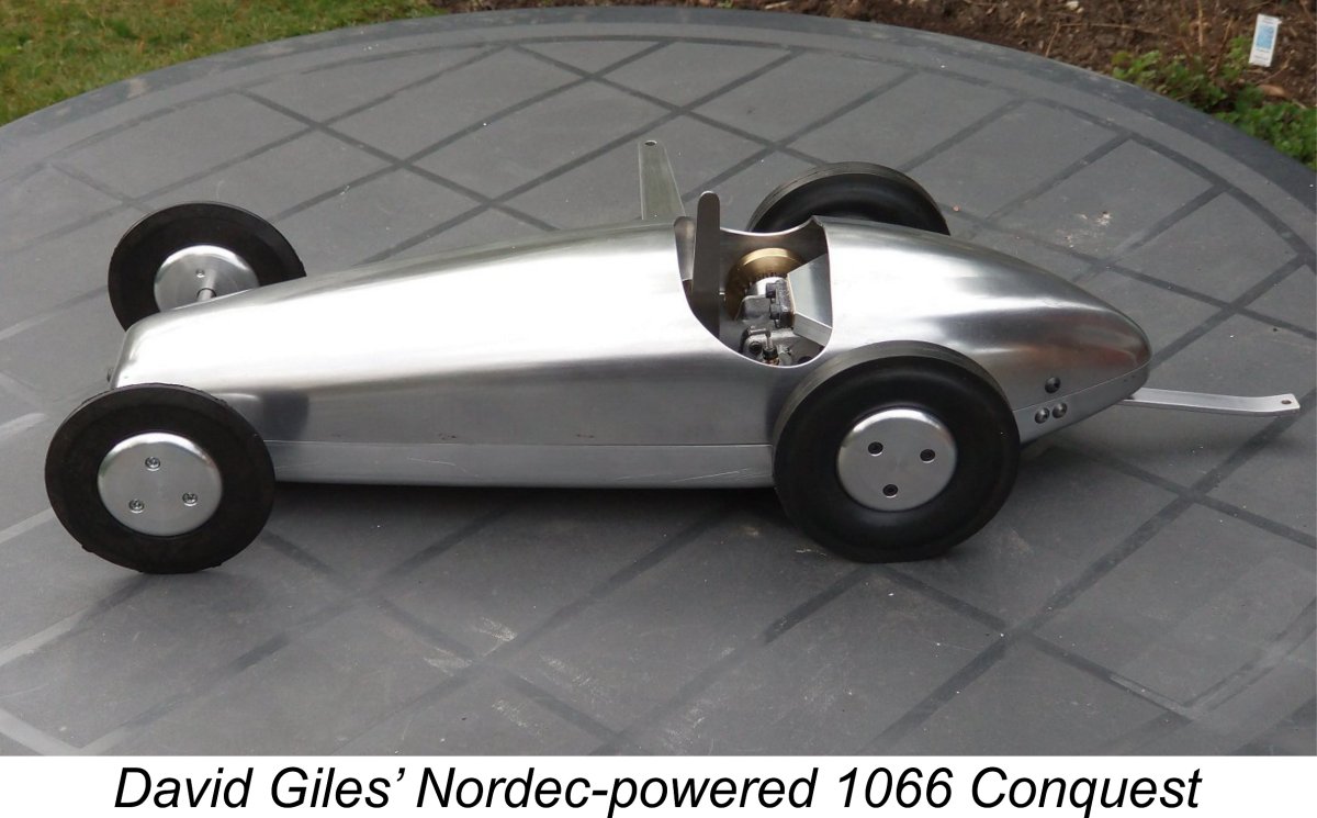
The columns of material left between the individual port apertures to prevent ring snag have been reduced to minimal thickness. Matters have been taken even further with respect to the two bypass entry ports which are supplied by the piston ports discussed earlier - the entire lower cylinder wall on that side has been removed, eliminating the two bypass entry ports in the cylinder liner altogether. Somewhat Alan's overall comment is that the cutting away of the exhaust ports has been taken to the extreme. He sees little benefit from lowering the exhaust port's lower edges other than the introduction of a very small amount of sub-piston induction, for what that's worth. Along with the larger inlet diameter, the implication seems to be that someone viewed the stock engine’s breathing as being unduly restricted. The fact that the rest of the internals look standard might suggest that changes were being made a step at a time, evaluating the effectiveness of each incremental step. A logical approach if so. My thanks to Alan for providing us with a look over the shoulder of John Wood or whoever was attempting to get more out of this engine! Conclusion If nothing else, I think I've proved that the Nordec RG10 had the potential to be quite competitive against the British opposition at the time of its release. In tuned form, it was more or less on par with the Rowell 60 and could show a clean pair of heels to the Ten-Sixty-Six Conqueror. Most of the modifications applied to the engine by its unknown previous owner could easily have been incorporated into the standard engine at little or no additional manufacturing cost - indeed, some of them were incorporated into the later Nordec Special series. It's clear that a little further development by the manufacturers at the outset could have brought the performance of the original Nordec at least up to par with the Rowell 60, which was the most powerful British 10 cc engine of its day. One suspects that a competitor of John Wood's calibre must have been well aware of the residual design shortcomings of the Nordec RG10 as introduced. The effort that has been put into Alan Strutt's "Test No. 4" unit seems to prove as much. The fact that the engine was released in what must be seen as a relatively undeveloped form must surely be down to the budgetary constraints placed on the initial development of the engine by Nordec company management, who saw model engines as a mere sideline to their main automotive business. Still, an interesting demonstration of the combined effectiveness of a series of intelligently-conceived and well-executed modifications to the basic Nordec design. I hope you've enjoyed reading about it as much as I did testing it! ______________________ Article © Adrian C. Duncan, Coquitlam, British Columbia, Canada First published August 2022 |
||
 If you’re sufficiently interested in the Nordec 10 cc racing engines from England to have opened this page, you’ve probably already read my in-depth history of the
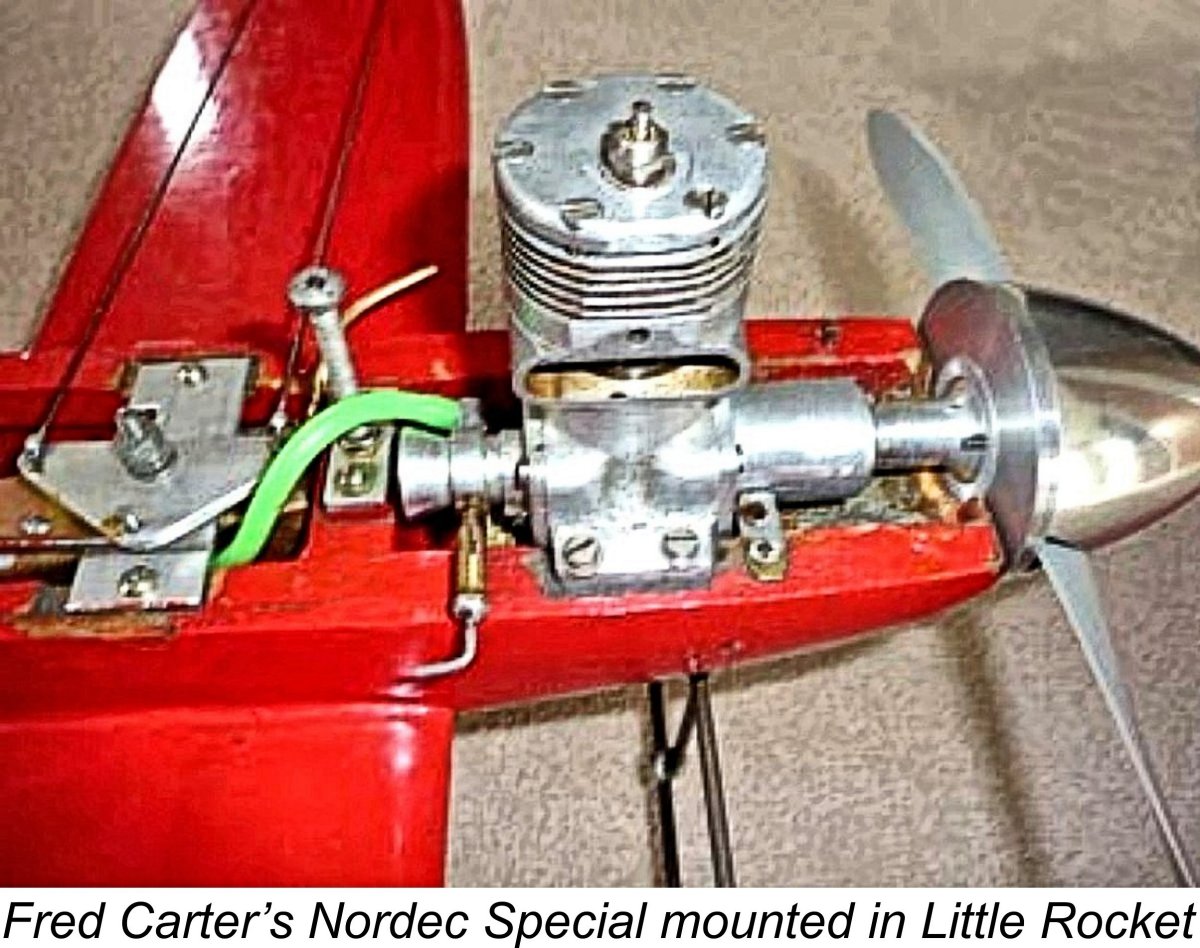
 actually somewhat unusual for a Nordec - a surprising proportion of the surviving examples seem to have spent relatively little time actually powering a model.
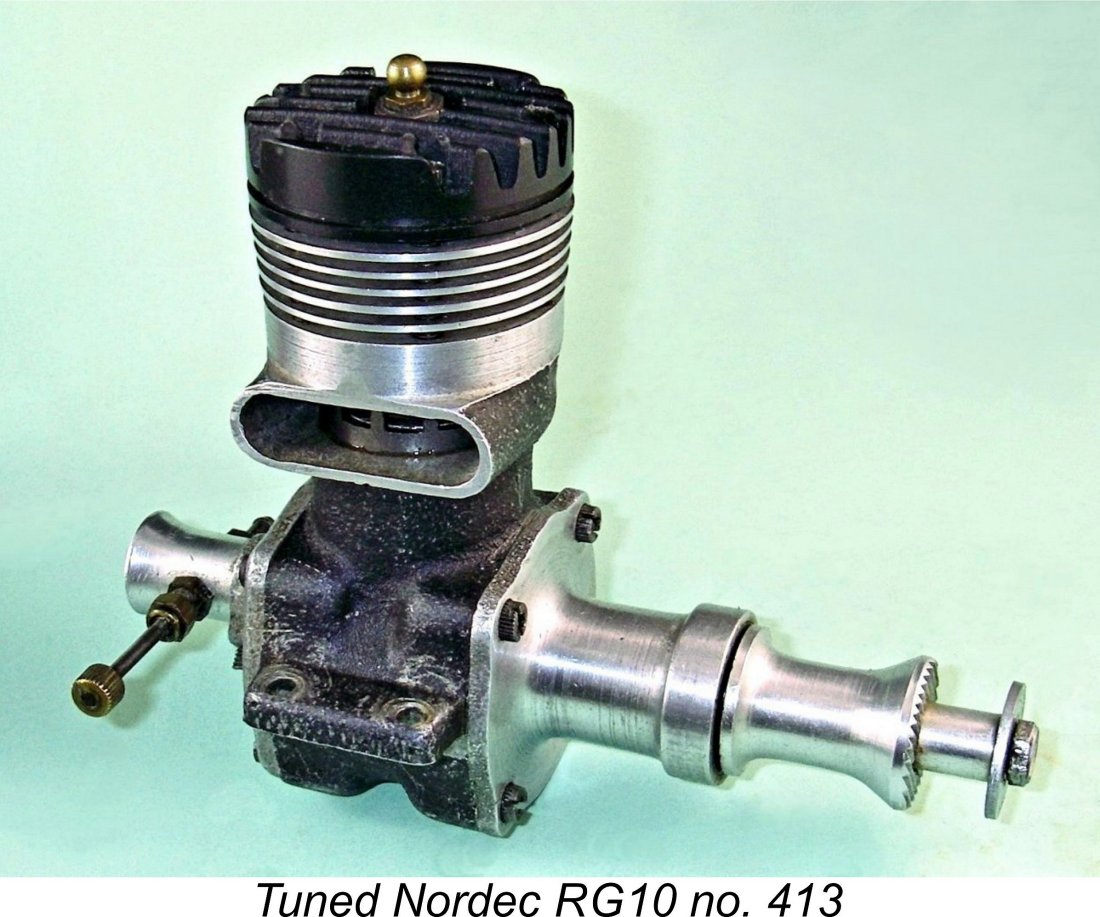
 Internally however it was a different story - a number of additional modifications had been carried out, most of which are invisible unless the engine is dismantled. I’ll spend some time summarizing these modifications and the reasons for their inclusion.
 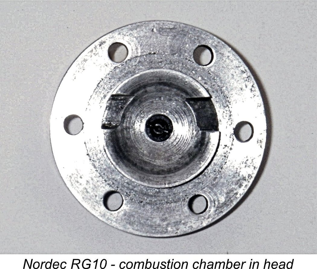 Presumably for production reasons, Nordec designer John Wood elected to use a cylinder head which was fully machined from bar stock. This decision greatly compromised the
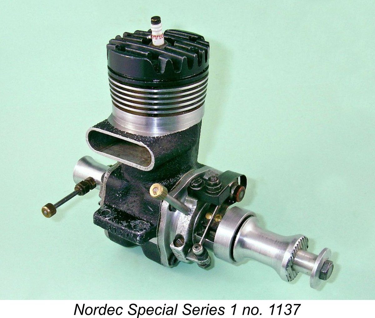
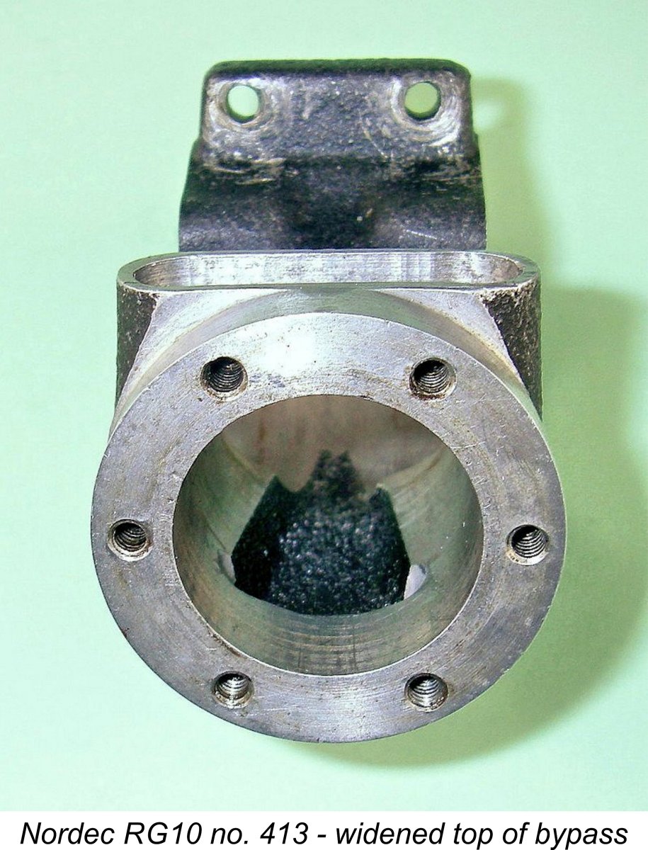 Of course, once that extra mixture is drawn into the crankcase, it has to go somewhere to make room for more! To facilitate this, the tuner turned his attention to the bypass and transfer porting. The standard Nordec’s bypass passage is conventionally formed in the main crankcase casting. It is relatively narrow, to the extent that when the engine is assembled, the outermost two of the four transfer openings in the cylinder wall are partially obscured by the inner bore of the crankcase casting into which the cylinder liner slips. This has the unhappy effect of obstructing about 20% of the already-marginal working area of the four transfer ports.
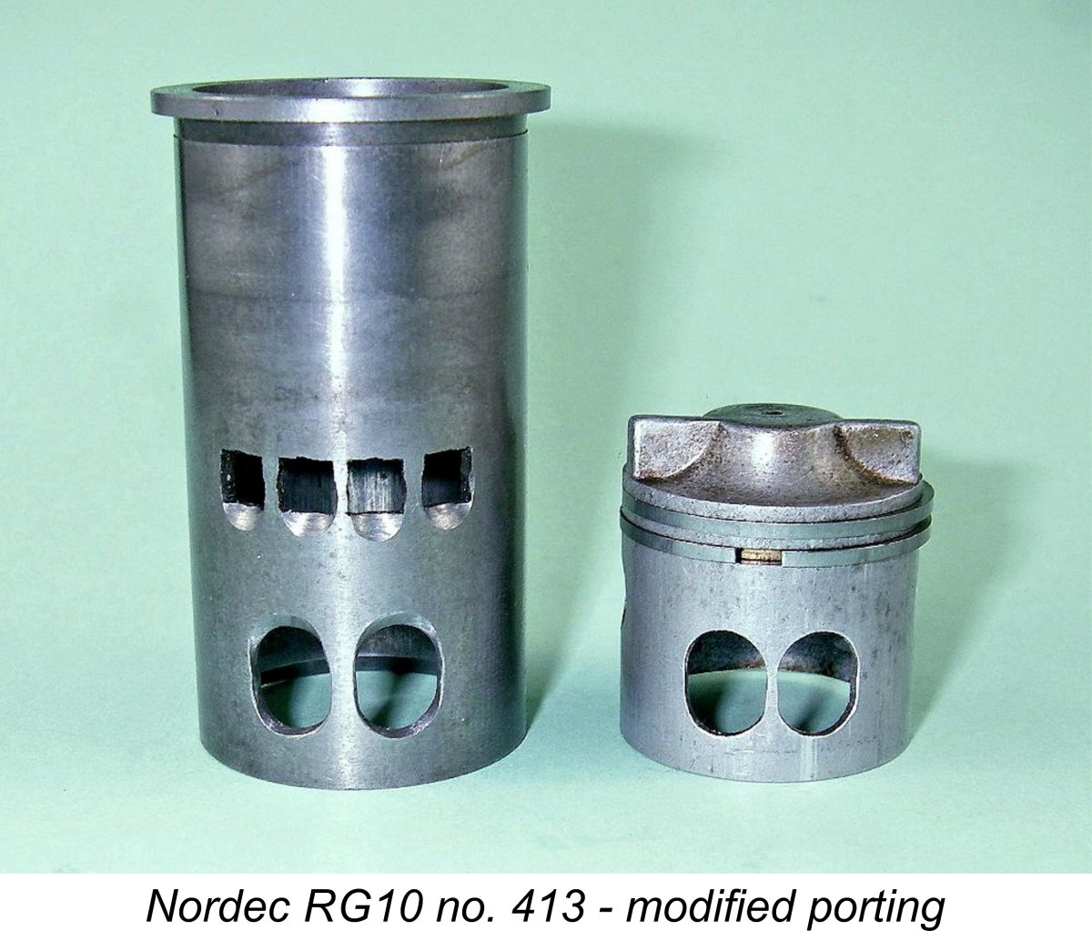
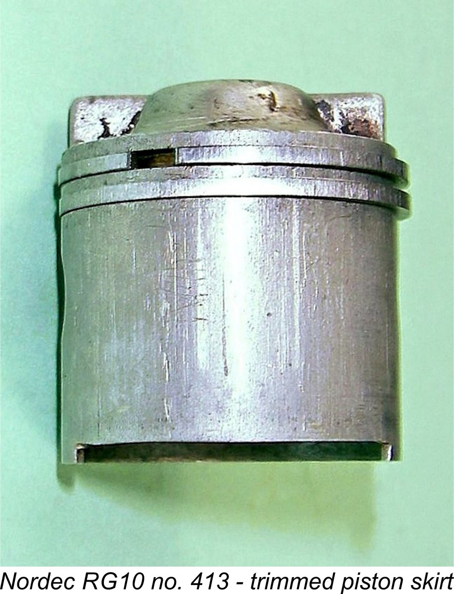 One modification which I would not have made if I had been trying to improve this engine was the shortening of the piston skirt on the exhaust side to give about ten degrees of sub-piston induction on either side of top dead centre. With the improvements in pumping efficiency which should result from the other described modifications, such an additional measure seems superfluous to me. Still, there it is………and it's undeniably true that sub-piston induction was a standard feature of the Nordec Special engines as supplied. This is almost certainly where our unknown tuner got the idea.
 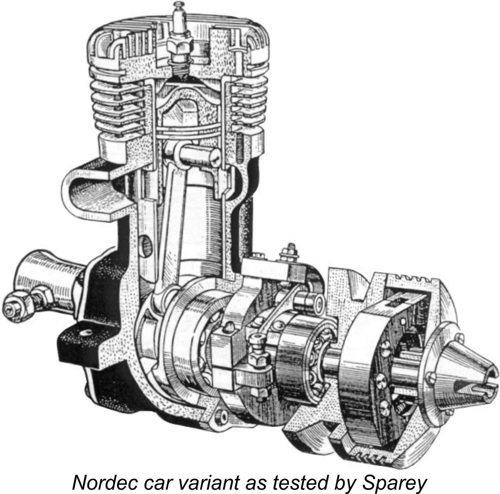 Clearly disappointed by the relatively mediocre performance measured for the glow-plug RG10, Sparey nonetheless proceeded to test the companion spark ignition R10 model. However, given that variant's more probable use in tether car service, he elected to present his findings in the April 1949 issue of "Model Cars" magazine.
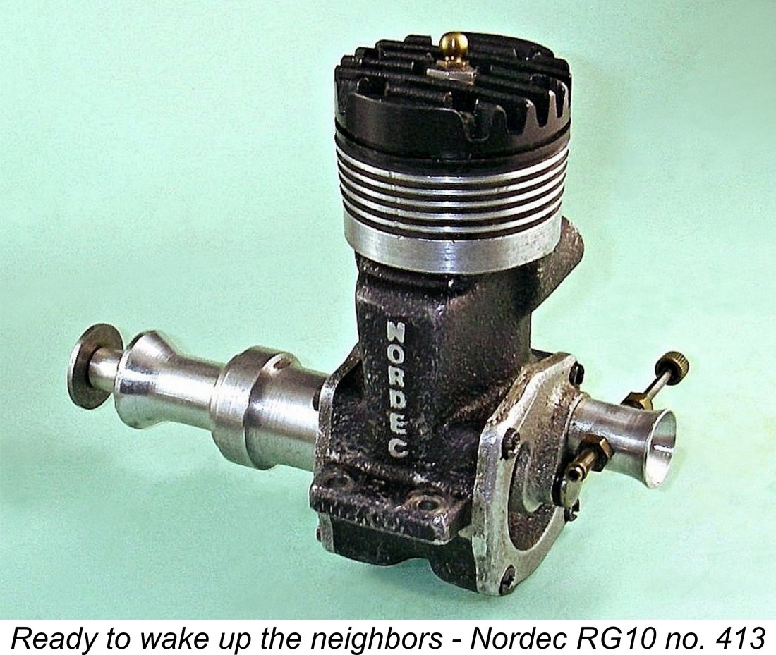
 Past experience with these engines led me not to expect miracles of performance from even the tuned engine number 413. The best that I was hoping for was that the tuned Nordec might approach the performance of the contemporary
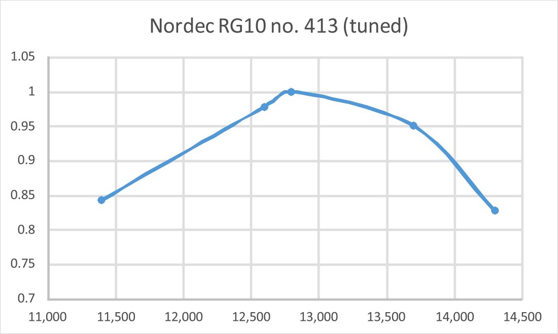
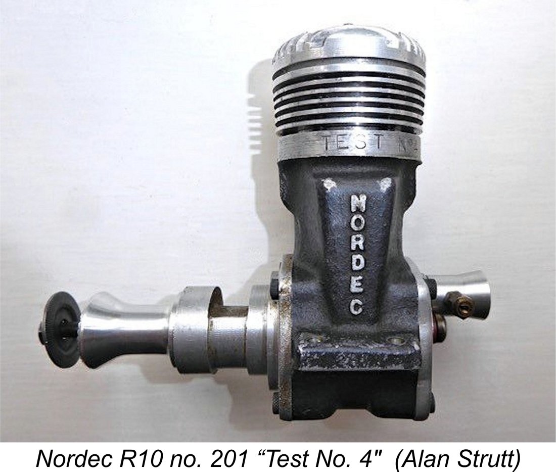 Upon hearing that I was preparing an article on a tuned Nordec, my English correspondent Alan Strutt was kind enough to send along some details of a heavily modified example in his possession. This engine started out as Nordec R10 no. 201, but was subsequently marked "Test No. 4" above the bypass. Although we can't prove it, Alan and I are in agreement that this marking was almost certainly applied by the manufacturer, making this a factory test unit. The idea seems to have been to explore potential approaches to the improvement of the stock engine's somewhat uninspiring performance. In all likelihood, John Wood was responsible.
 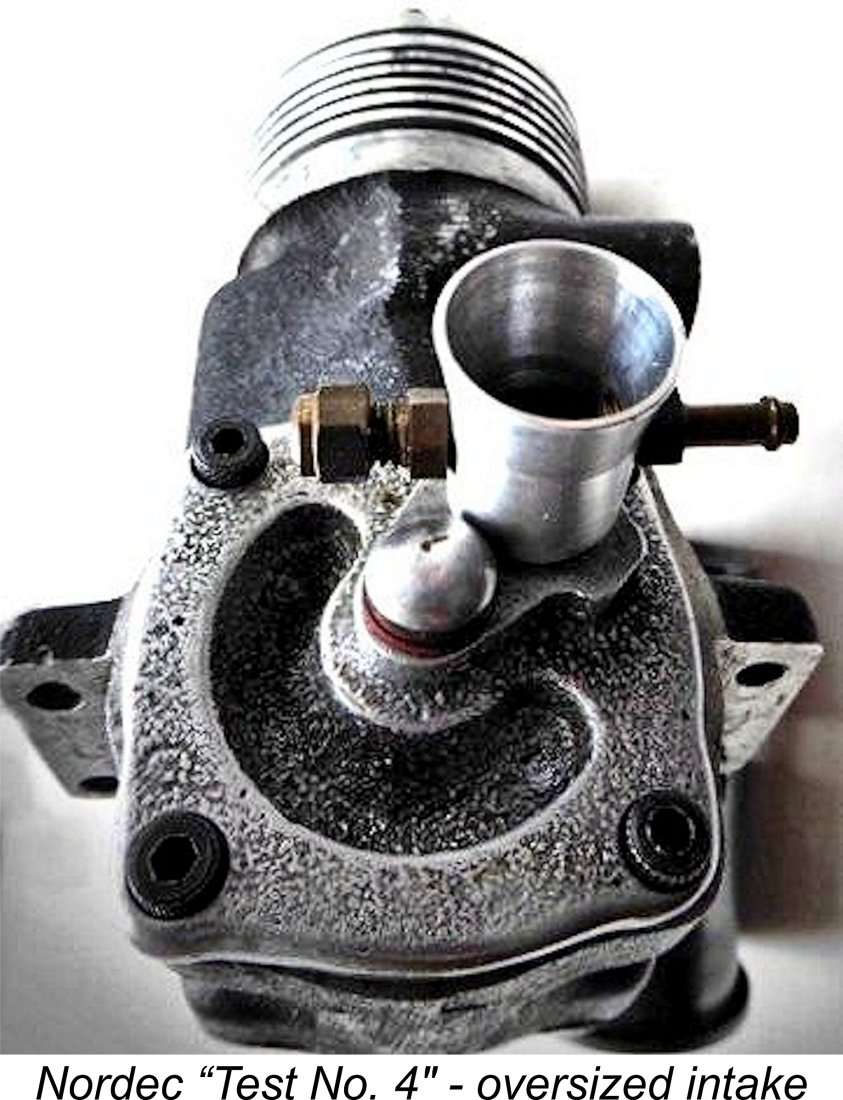 Outwardly, the engine looks just like any other Nordec, except that the inlet venturi has a very slightly larger diameter than the standard component. The major effort has been directed towards the cylinder liner. The dimensions of both transfer and exhaust ports have been significantly increased, both vertically and horizontally. This has resulted in a substantial increase in port areas as well as a change in the port timings. The lower edges of the exhaust apertures have been lowered to the extent that the engine has a modest period of sub-piston induction.
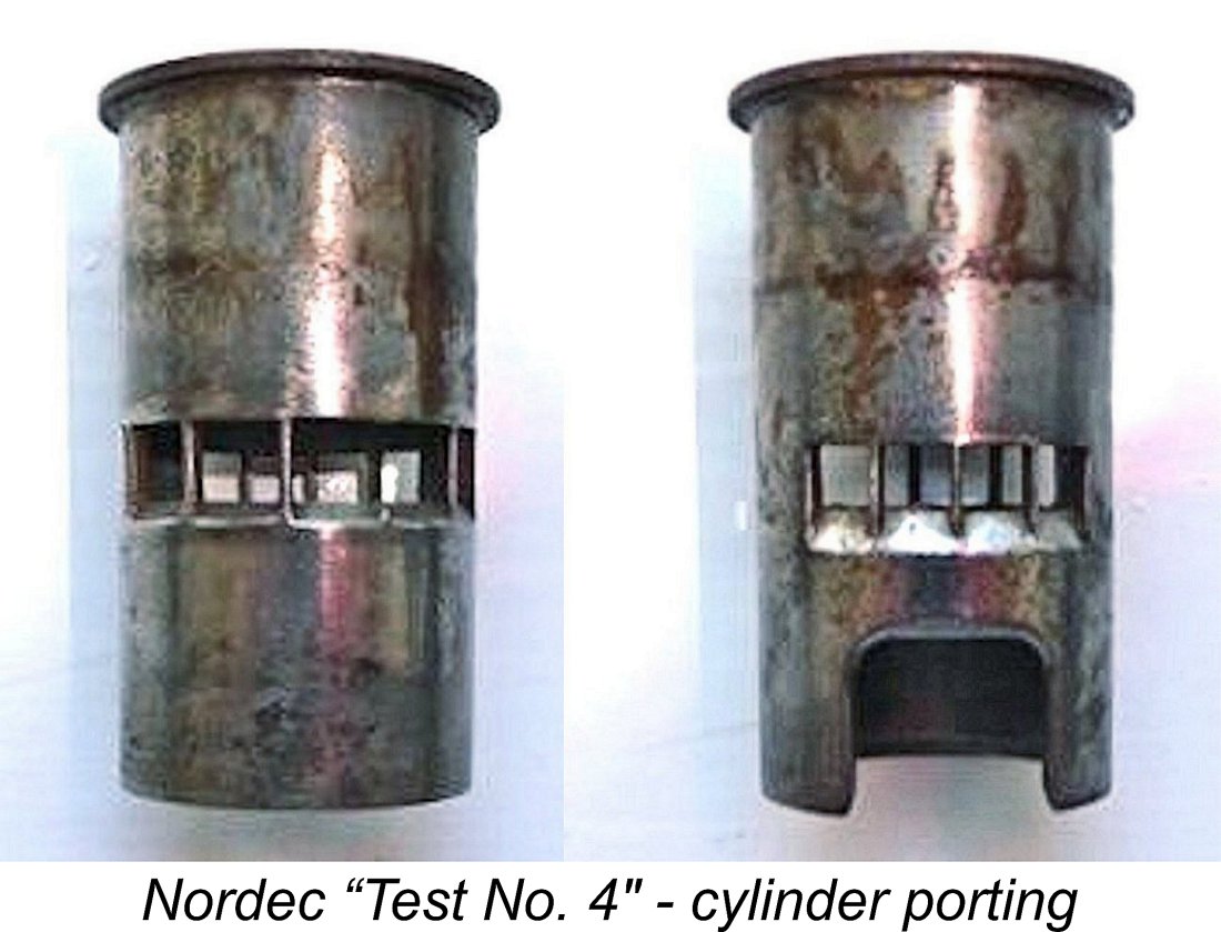
| |