
|
|
Fresno Flyers - the Hornet Racing Engines
The original version of this article appeared in March 2012 on the late Ron Chernich’s ever-informative “Model Engine News” (MEN) website. I’m re-publishing it here because my mate Ron left us in early 2014 without sharing the access codes for his heavily-encrypted site. Because no maintenance has since been possible, the MEN site is slowly but perceptibly deteriorating as the various links fail progressively - an inevitable process which can have only one ending in the long run. I thought that it would be a shame to risk the potential loss of reader access to the information on the Hornet, hence the article’s re-publication here. I’ve also taken the opportunity to bring certain aspects of the story up to date. In order to fully appreciate the true significance of the Hornet design, it's necessary to wind back the clock to examine the chain of events leading up to its development. So let's begin as usual by setting the stage....... Background Most present-day model fliers seem to think of their hobby as a relatively "modern" high-tech form of recreation. It thus comes as something of a shock to some present-day modelling aficionados (including myself when I first came to think about it!) to realize that the sport of I/C power modelling is now well into its second century! Indeed, R/C model flying is getting up there as well, having been first demonstrated in the mid 1930's. Miniature I/C engines potentially suitable for model aircraft use began to emerge from the workshops of talented home constructors in the first decade of the 20th Century. The great innovator Ray Arden recalled his own first encounter with an I/C powered model aircraft in 1907 when he was 17 years old, the constructor of that model and motor being one A. N. Herring. Ray being Ray, it goes almost without saying that by 1908 he had designed and constructed an engine of his own which he used successfully to power a 6 foot wingspan model biplane. The rest, as they say, is history ..........
Although a limited number of small I/C engines potentially suitable for model use continued to be offered for sale in various parts of the world from 1910 onwards with a major break during WW1, the 1931 introduction of the Brown Junior spark ignition motor in the USA is generally considered to mark the first significant step towards the large-scale commercial Despite the fact that the Great Depression was in full swing at the time, the Brown was developed quite rapidly and was quickly challenged by a number of rival products, predominantly manufactured in the USA. The human race being the competitive species that it is, contests for power model aircraft soon became quite fashionable among serious modellers. Check this link to see a newsreel film of the 1936 US National Championship, in which the Brown Junior is prominently featured. Now it's important for context to remind ourselves at this point that power aeromodelling was exclusively free-flight during the pre-WW2 years. Moreover, performance-oriented competitions for I/C-powered model aircraft at this time were based strictly upon flight duration. The first priority was simply to get the model into the air, and the second was to keep it up there as long as possible on a given engine run. Speed didn't enter into the picture at all at this stage. The development of tethered model aircraft operation (aka control line), which allowed the safe attainment of high speeds under full control while also facilitating accurate speed measurement, still lay some years in the future.
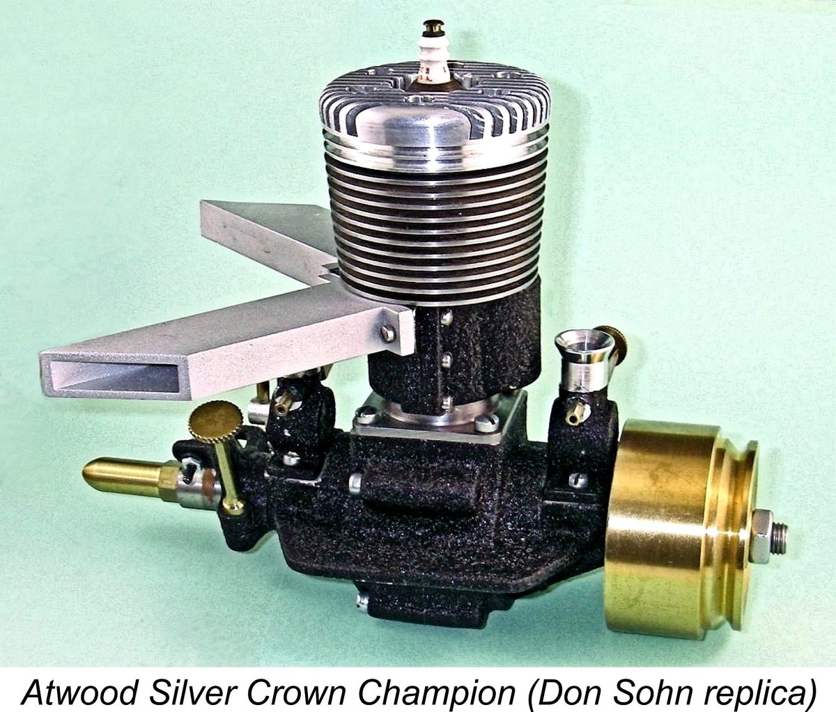
Considerations of commercial availability meant that those pioneer car and hydroplane racers who were unable to make their own engines had to use powerplants which had originally been intended for model aircraft use. Atwood, Super Cyclone and Dennymite engines were widely favored for these applications during the early years. However, it soon became apparent to the more savvy By contrast, competitions for tethered model cars or hydros were all based upon one criterion - raw speed! Accordingly, the primary requirements for engines intended for such applications were the highest-possible peak power output coupled with a high level of structural integrity to withstand the spectacular revs sometimes attained during the start-up procedure. Weight was far less of an issue for car engines in particular, since none of the engine's power had to be diverted to the creation of lift as opposed to speed. In fact, high weight applied to the driving wheels had the advantage of promoting improved traction. It should be clear from the above discussion that while there was no incentive at the time for the development of all-out "racing" engines for aircraft use, such an incentive was front and centre when it came to engines intended for car or hydro applications! This made it inevitable that the development of the first truly high-performance model engines would be largely carried out by the model race car fraternity, with the tethered hydroplane crowd also taking a hand in the game.
The successful efforts of Dick McCoy in this field have already been covered at length elsewhere. Here I’ll focus on the engine that may well have provided Dick with both his greatest source of inspiration and his stiffest competition during his early years as a racing engine designer - the Hornet 60. As stated at the outset, this engine marked a turning point in the history of model engine design, making it only fitting that as power modelling moves into its second century, we take time to recall such a moment. But before I begin, it's necessary as always when writing about an American model engine range to acknowledge my indebtedness to my mate Tim Dannels, former Editor of the sadly now-discontinued “Engine Collectors' Journal” (ECJ). Tim's indispensable “American Model Engine Encyclopaedia" (AMEE) is a required reference for anyone having an interest in the products of the American model engine industry, and I freely acknowledge having made frequent reference to that work during the preparation of this article. Thanks, Tim! A Forerunner - the AC Special As of the latter part of the 1930's, the State of California had become perhaps the leading geographic area in terms of participation in the burgeoning hobby of model car racing. Dick McCoy himself was of course a California resident, along with many other model car racing luminaries of the day such as the Dooling brothers, Ira Hassad and Bill Batzloff. California was also home to a significant number of pioneering model engine manufacturers. All of the required ingredients were there ....... In Oakland, California, a pair of model car racing enthusiasts named Walt Cave and Charlie Anderson (seemingly no relation to Mel Anderson) looked over the competition and decided that they should be able to come up with an engine which would be far better suited to the requirements of model car racing than any of the then-available commercial model aero engines. In 1938 they developed an engine design in which maximum power output and durability were the primary design criteria. Since the engine was intended from the outset for model race car use, weight control was very much a secondary design consideration.
The construction of the engine was a little unusual in that the main casting terminated vertically in a flange just above the mounting lugs, with the cylinder liner being retained in a separate casting which incorporated the exhaust stack, bypass passage and cooling jacket. This assembly was attached to the main crankcase with four screws passing through the corners of a matching flange below the level of the exhaust stack. The configuration had the advantage of allowing for servicing of the piston, rod and rings without the need to disturb a good head seal. It also greatly facilitated the fine-tuning of the cylinder port timing, since that timing could readily be adjusted without disturbing the liner simply by inserting shims of varying thicknesses between the cylinder base and the upper crankcase. The head could of course also be re-shimmed as required. The rear disc rotary valve was carried in a separate casting which aligned with a vertical central split in the crankcase across its axis, thus forming the rear half of the crankcase. The two designers established a company known as A.C. Motors to manufacture the A.C. Special. The production engines had the designation "AC SPL" cast onto the bypass. However, very few examples of this engine were manufactured. It is consequently mega-rare today - I have no personal knowledge of any surviving examples, although they do exist. Nonetheless, it is an extremely significant engine in a historical sense because it marked the advent of the "classic" model racing engine. The Hornet Makes Its Debut The performance of the A.C. Special with its then-groundbreaking design features was sufficiently promising that the prospects for its wider marketing were clearly good. However, the two designers of the engine evidently lacked the resources to fully realize the engine's marketing potential. An injection of additional capital and expertise was required.
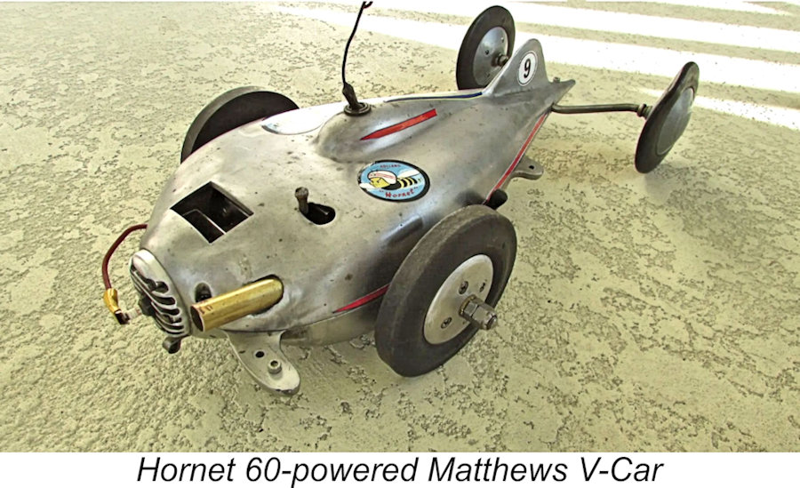
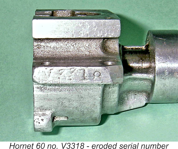
Ray Snow was also a model car racing enthusiast, which was presumably the common thread that brought him into contact The nature of the agreement between Anderson, Cave and Snow which led to the establishment of Hornet Motors and the manufacture of the Hornet engine remains unclear. The geographic distance between Oakland and Fresno makes it appear highly unlikely that Anderson and Cave had any hands-on involvement in its manufacture - a three-way split of the anticipated profits from a small-scale model engine manufacturing venture would scarcely have been seen as sufficient to warrant their relocation from Oakland to Fresno. They may simply have entered into a In general, the 1939 Hornet 60 followed the trend-setting design of the A.C. Special very closely. It had bore and stroke measurements of .940 in. and .875 in. respectively for a displacement of .607 cuin (9.95 cc). All-up weight was a healthy 16¼ ounces without flywheel or ignition support equipment. Once again, sand-castings were employed throughout, the main bearing housing being cast integrally with the crankcase. This model featured a fully machined con-rod as well as a crankshaft which was produced by machining from bar stock. The carburetor assembly was machined from brass and featured a surface-jet needle valve assembly. At this stage, the stubby parallel-sided straight intake tube of the A.C. Special was retained. A 3/8-24 spark plug was used in these 1939 engines. The main point of departure between the Hornet and A.C. designs was the crankcase/backplate assembly. In the Hornet, the mounting lugs were relocated significantly further aft than those on the A.C. Special, the vertical split in the crankcase being accordingly moved towards the rear as well. Since the backplate conformed to the entire cross section of the main crankcase, the cylinder attachment flange consisted of two carefully-matched sections. The backplate was secured to the rear of the main case by four screws, after which the upper surface of the This arrangement resulted in two of the cylinder assembly screws being threaded into holes tapped in the upper surface of the main crankcase casting, with the other two being threaded into holes tapped into the top of the separate backplate casting. This naturally meant that removal of the backplate to service the disc valve required the prior removal of the upper cylinder unit. A bit awkward at times, perhaps, but there's no doubt that this made for an extremely sturdy and stiff assembly. It also facilitated servicing of the piston and rings, as noted earlier. However, it imposed a very high standard of machining precision on the manufacturing operations. The fact that the main casting and the backplate had to be machined as an assembled unit to create the cylinder mounting surface and location recess made it appear pretty much essential to keep matched components together as a set following machining. Presumably for this reason, these early engines carried matching serial It should now be clear that the manufacture of the Hornet involved the production of a number of high-quality sand-castings - the main crankcase, the backplate, the upper cylinder, the cylinder head and the timer frame. For the most part these castings were produced by the Matthews Foundry Company of Fresno. The owner of that company was Percy Matthews, a fellow model car racer who was one of Ray Snow's closest friends. Percy Matthews died during WW2, but his company carried on after the war, producing the famed teardrop Matthews V-Car, which was one of the early post-war pace-setters, being the first car to break the 100 MPH barrier, naturally using a Hornet engine. They also carried on producing the Hornet 60 castings, with the V prefix being applied to the serial numbers of the post-war Hornets.
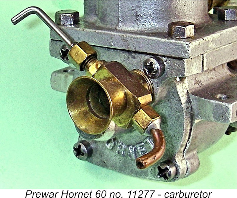
The very ingenious answer is that the brass venturi is actually made in two parts. The screw-in section is a simple tube with a slightly reduced external diameter at the rear which creates a shallow shoulder just forward of the needle valve location. This shoulder serves to locate the second component, which incorporates both the bell-mouth intake and the needle valve installation block. This component slips over the reduced diameter of the rear end of the screw-in section to butt up against the shoulder. The threaded holes for the needle Clearly, the drilling and tapping of the needle valve holes was first carried out with the two components assembled to ensure matching of the threads. They were then separated to allow the threaded venturi tube to be installed in the backplate, after which the needle valve mounting was pushed into position and locked there through the installation of the needle valve components. One can easily see the interface between the two venturi components simply by looking into the bell-mouth intake. The bore of the venturi was a relatively modest 0.325 in., which had the advantage of allowing the engine to operate satisfactorily on suction feed. The majority of these engines were built and sold in race car configuration complete with flywheel. A few examples were produced for use in aircraft by those brave enough to release such power (and weight!) into the air in a free flight model (no control line or reliable generally-available radio control at this stage!). These aero models featured a steel prop driver with a square recess at the rear which dovetailed onto a square section of shaft just forward of the front ball-race. The shafts in the aircraft models were also made slightly longer to accommodate the anticipated range of airscrews. In his invaluable AMEE, Tim Dannels reported that some 250 examples of the Hornet 60 were manufactured in the form just described with the 3/8-24 plug, thus making it by far the rarest version of the engine. This information is inconsistent with the fact that engine numbers 980 and 1934, both having 3/8 in. plugs, came to light following the original publication of this article on MEN.
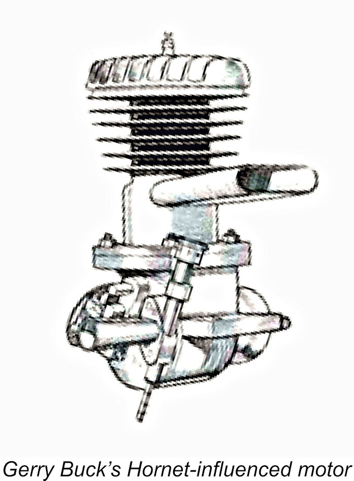
The revised 1940 model of the Hornet 60 was once again very similar indeed to its predecessor, although there were a few changes designed both to enhance the engine's mechanical reliability and to facilitate production. A new forged con-rod replaced the former all-machined item, along with a crankshaft which was now machined from a forging as opposed to bar stock. In both cases, machining time was reduced and strength was enhanced. The advent of ¼-32 spark plugs did not go unrecognized either - the new model featured such a plug, actually being one of the earliest big-bore model engines to do so. My friend and colleague Marcus Tidmarsh has done an enormous amount of work researching the serial number sequences applied to the Hornet engines. The numbers applied to the pre-war Hornets were stamped on both the front and rear of each engine. The numbering sequence applied to the pre-war productions evidently started at engine number 1 (or possibly 100) and continued without a break through the switch to the ¼ inch plug in 1940 to a high of somewhere in the region of 4500 - Marcus has confirmed serial numbers for these units ranging from a low of 120 to a high of 4042. This figure makes it appear very probable that Ray Snow must have continued his machine shop activities relating to the full-sized sprint car scene as well as the agricultural activity which characterized the area around Fresno at the time. Sales of model engines at the implied levels over a two-year period could scarcely supported Ray and his growing family on their own. To allow for use in the unrestricted Open class, a very few examples of this model were made to special order with an enlarged bore of 0.970 in. as opposed to the standard 0.940 in. In competition terms, the Hornet was an immediate and overwhelming success, quickly becoming the dominant powerplant in its class. Its success was by no means confined to the USA - the Hornet was to become equally dominant in Britain, Australia and elsewhere, its adoption outside the USA being mainly constrained by considerations of availability. Wilf Rowell of Rowell Motors fame became a Hornet user in 1947, which explains the clear Hornet design influence visible in his iconic Rowell 60 of 1948. Spurred by this success, the production of the Hornet 60 continued through 1941 more or less up to the entry of America into WW2 in December of that year. By this time, Dick McCoy's first self-constructed engines had begun to appear in car racing circles. There's little doubt that the design of the Hornet exerted With the onset of WW2, Ray Snow's manufacturing capabilities were naturally re-directed towards wartime production. This ended the pre-war phase of Hornet manufacture. Dick McCoy was similarly engaged throughout the wartime years. However, he and Ray were naturally well acquainted with one another through their many meetings at model car racing events, and they seem to have remained on cordial terms throughout. At some point during the war years, Ray actually approached Dick with the proposal that they join forces after the war to produce the world's fastest model racing engines. The fact that Dick was reportedly attracted to this idea is a reflection of the respect in which he held Ray Snow. However, a prior agreement which Dick had signed with Fred Schott of the Duro-matic Products Company in Hollywood, California, precluded any such partnership. The Post-War Hornets
Ray Snow elected to pick up the pieces of the pre-war Hornet operation and carry on more or less from where he had left off in late 1941. As noted earlier, it's clear that whatever negotiations had resulted in the discontinuation of the former partnership had left the design and further development of the Hornet 60 firmly in Ray's hands. Ray had conducted his wartime production activities under the banner of the patriotically-named Victory Tool & Die Corp. It appears that this company must have been very active during the war years, since by the end of the conflict the operation had been relocated from the former Fulton Street premises to a new more spacious location a little to the east on Ventura Boulevard, apparently occupying both 3847 and 3849 Ventura Boulevard.
The post-war Hornet was made in three distinct styles. The first of these was the Hornet 60-A, intended for model aircraft use. By this time, the advent of Jim Walker's U-control system (far better known today as control line) had made the safe operation of high-speed tethered model aircraft a practical reality, the result being that speed contests for control line models were becoming increasingly popular. For the first time, pure racing engines could be stretched to their limits in a model aircraft context. The Hornet 60-A quickly established a number of American records in this category to add to its earlier successes in the car and hydroplane fields. At one point the various forms of the engine simultaneously held every American airplane, car and hydroplane records for all of the classes in which the Hornet was eligible. Quite a statement!
The Hornet piston featured a pair of circular skirt ports which aligned at bottom dead centre with two similar ports cut in the cylinder wall. These ports are in fact very necessary - the entry to the lower end of the bypass passage is extremely small, as the attached image will show. Without the piston ports, the engine would likely asphyxiate itself well before true racing speeds were reached. Even with these ports, the bypass/transfer setup is probably the limiting factor in terms of Hornet performance.
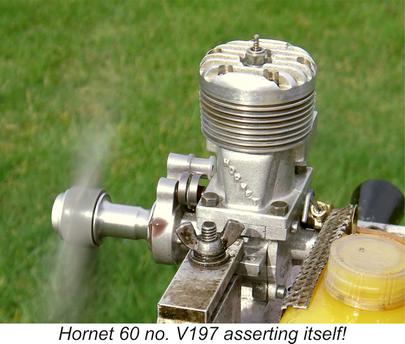
The crankshafts too were very similar, and in fact a McCoy crankshaft will fit an early race-car Hornet without modification. However, there were a few differences between the two crankshaft designs. Both components featured integrally-machined crescent- At this point, it's necessary to draw attention to an issue which only became clarified during the original writing of this article. This is the fact that there were two distinct sizes of front ball race used in the Hornet. All versions used a shaft having a major journal diameter of 0.500 in., the rear ball race in all cases being a standard 1.125 in. x 0.500 in. component. However, matters were different at the front. The early car and boat versions had shafts which carried the nominal 5/16 in. (0.3145 in) diameter of the prop mounting thread all the way through the front bearing to the shoulder at which the shaft expanded to its full 0.500 in. diameter. Presumably for reasons of availability, the makers chose to use a metric 22 mm x 8 mm (0.866 in. x 0.315 in.) front bearing for the early post-war engines fitted with the car or boat shaft. I was extremely surprised to discover this, but I had two engines available for direct measurement during the preparation of this article, and the matter is beyond dispute. My late mate David Owen confirmed this observation, also pointing out that the use of metric bearings was actually not all that uncommon in the USA during the period of which we are speaking. This was because the bulk of world ball bearing production had taken place in Europe up to that point. The McCoy 60 used an identical front bearing, as I confirmed by direct measurement. When it came to the aero version, the presence of the square section forward of the front bearing to key the prop driver necessitated a 0.375 in. diameter section passing through the front bearing. The front bearings in these models will be found to be standard 0.875 in. x 0.375 in. items. The really interesting thing about all of this is the fact that the post-war manufacturer's parts list cited the same case and front bearing as being suitable for all three models! At the outset at least, this was clearly incorrect - while I was finalizing the original text of this article I had dismantled examples of low-serial number aero and car types on my bench at the same time, and the different front bearing housing diameters were directly checkable and therefore indisputable. The car crankcase having the smaller O/D front bearing has not been sleeved down - it is machined to the appropriate 0.866 in. dimension. The explanation of this apparent anomaly appears to be that the car and aero versions were indeed distinct at the outset. However, the design of the car shaft was soon changed to allow it to be fitted into an aero crankcase/bearing assembly, thus standardizing the cases and front bearings in accordance with the parts list. This would make complete sense if the aero version was trending towards becoming the main product, as seems not unlikely given the rapidly growing popularity of control line speed flying at the time. It would make little sense to continue to machine the same crankcase casting to two distinct specifications as well as having to supply two different front bearings. I've so far been unable to establish the point in the serial number sequence at which this change was made other than to suggest that it was almost certainly quite early on in the post-war production sequence. All I can state with certainty is that engine number V197 has the smaller front bearing and was clearly originally intended for car use using the earlier shaft. By contrast, earlier engine number V167 has the aero shaft with the larger front bearing, seemingly confirming that the cases were machined concurrently to two distinct front bearing specifications, at least for some time prior to standardization.
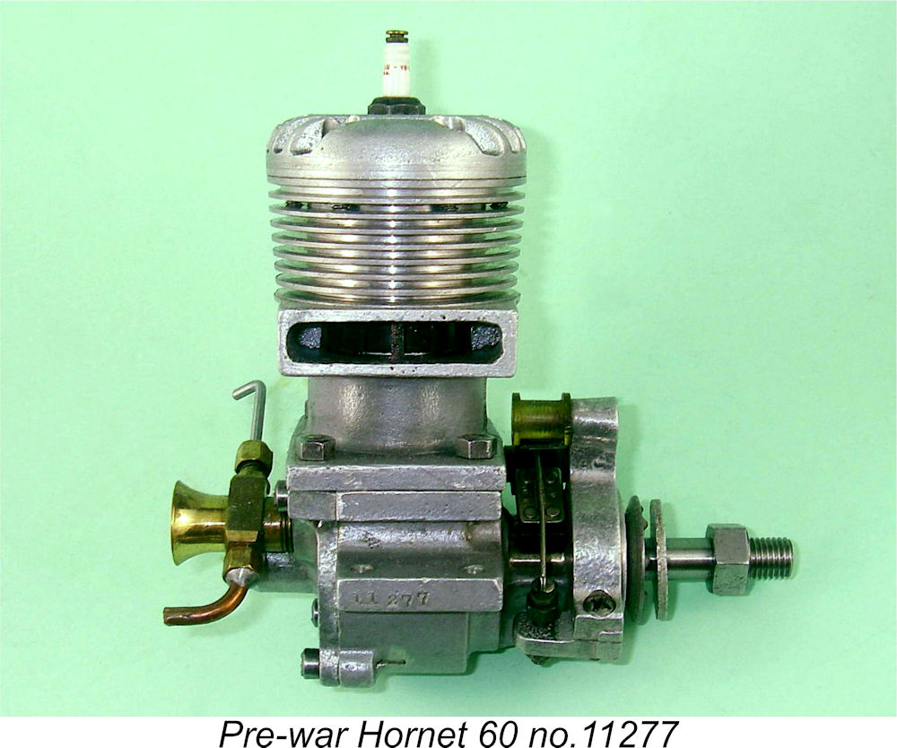
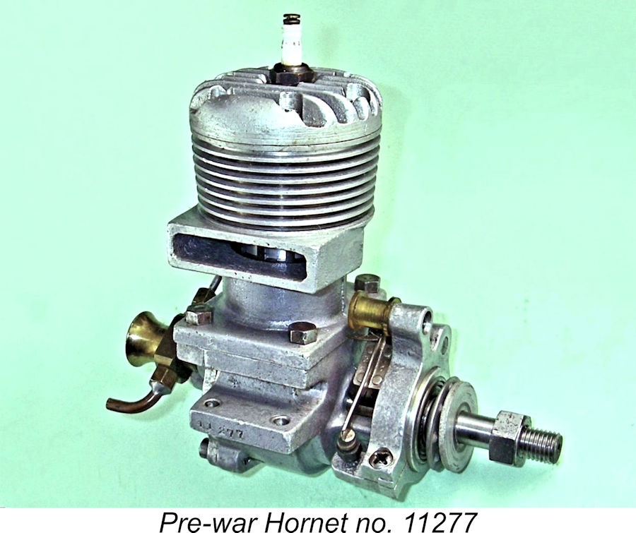
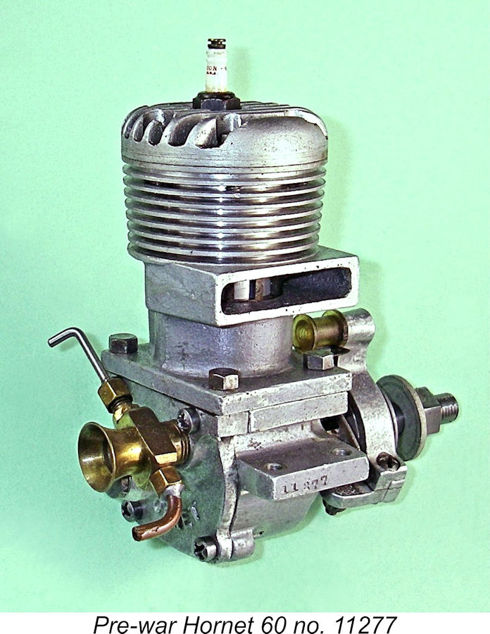
Apart from the differences in the crankshafts and front bearings, there were a few other minor variations in the design details of the three versions of the Hornet, but for all practical purposes they were the same engine. As with the 1940/41 models, they all bore serial numbers, although these were now placed on the right-side mounting lug. The numbers on the post-war Hornets now had a V prefix to indicate that they were products of the Victory Tool & Die Corp. The presence of this letter is a dead giveaway for a post-war example of the Hornet. Notwithstanding the manufacturer's actual identity, the engines continued to be marketed under the Hornet Motors designation, the stated address being that of the Victory Tool & Die Corp. at 3849 Ventura Boulevard in Fresno, California. Marcus Tidmarsh has confirmed the existence of V-prefixed engines bearing numbers from a low of V22 to a high of V10754. However, at around this point the V prefix was dropped, presumably due to the increasing length of the numbers, making it challenging to hand-stamp them on the relatively short engine mounts. Removing the "V" sped up the stamping process a little and required less precision in striking. Marcus confirmed the existence of engines numbered in this way ranging from a low of 10830 up to a high of 12002. My illustrated engine number 11277 is one of these units. In terms of total production, Marcus's research indicates that perhaps 4,500 engines were manufactured during the pre-WW2 period, with another 12,050 examples being produced post-war. The total number of engines produced during the Hornet's entire production lifetime thus appears to be in the order of 16,550 units. Promotion of the Hornet 60
Further commentary on the Hornet 60 appeared in an article by Edward G. Ingram entitled "Recent Model Engines" which was published in the June 1946 issue of “Model Airplane News”. Since Ingram seems to have been quoting information obtained directly from Ray Snow, it seems worth reprinting the two paragraphs relating to the Hornet in full here given the level of detail which is provided regarding the engine's material specification. "The post-war model of the Hornet, which may be described as an engine in the high-priced class designed for high power output, is now in production. It is a Class C engine with a bore of 15/16" and a stroke of 7/8 in., giving a piston displacement of .604 cuin Two ball bearings support the crankshaft. Material specifications include 356T6 aluminium alloy for the cylinder, crankcase and rotary valve, 14T2 aluminium alloy for the cylinder head, which is attached to the cylinder with 6 screws, and 142T571 aluminium alloy for the piston. The connecting rod is forged from 14S dural and provided with bronze crankpin and wrist pin bearings. There are three intake openings and six exhaust openings in the cylinder, which is attached to the crankcase with 4 screws. A Meehanite iron cylinder liner is provided.
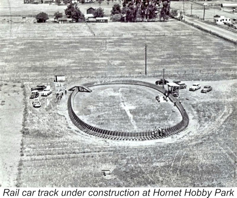
In their advertising, Hornet Motors stressed the fact that the various alloy components all had their own individual material specifications. The above commentary seems to bear this out. The performance claims in the advertising copy were fractionally higher than those cited by Ingram - the ads claimed 0.85 BHP @ 14,000 rpm, which was doubtless attainable by a good example. This was a considerable step forward from the 0.55 BHP @ 15,500 rpm claimed for the original 1939 model. Note that these figures related to the engine's operation on straight fuel - the introduction of the use of nitromethane by the Dooling Brothers still lay in the future. I'm unable to confirm the cited weight of the engine - my examples all weigh around 16¼ ounces bare. The advertised selling price of the engine in 1946 remained $35.00 - no small sum by the standards of the day, even in America! Clearly, modellers were expected to pay handsomely for quality and performance. Ray Snow was indefatigable in promoting the Hornet, which by this time had clearly become an important source of income for him. He went so far as to establish a purpose-built facility for model car and boat racing near his hometown of Fresno.
In summary, as 1946 moved into 1947, the Hornet remained at or near the top of the heap as a leading competition engine. However, this happy situation was not destined to last - other designers had their sights firmly set on creating their own engines that would put the Hornet in its place! Increased Competition
However, this could not last. By 1947 a host of other racing engine manufacturers had appeared on the scene. Moreover, the performances then being achieved by the better examples of some of these competitors were surpassing anything that a standard Hornet could manage. As of 1947 a typical example of the McCoy 60 was claimed to be good for around 1.0 BHP at 13,000 rpm. A well-prepared Hornet could just about match this, but things were definitely tightening up. New models from the likes of Ball, Orr, Hassad and Bungay weren't helping either.
In 1948, two significant events occurred. One, the commercial miniature glow-plug developed by Ray Arden had begun its rise to domination of the American model engine scene. Two, in response to the very serious challenge posed by the Dooling 61, the McCoy 60 was updated to produce the famous Series 20 model which was to remain the world 10 cc standard for the next 15 years or so. Both of these developments put the Hornet well and truly behind the 8-ball. For a time at least, modified examples of Ray Snow's engine continued to do quite well in competition, although outright wins became few and far between. In a companion article on this website, I've documented the efforts of one Hornet enthusiast to keep his engines competitive. However, the writing was clearly on the wall for the Hornet in what was essentially still its pre-war configuration. It's actually a testament to the excellence of the original 1939 design that it was able to remain competitive for as long as it did.
To improve the combustion qualities of such radical mixtures and keep the castor oil in solution, modellers resorted to the addition of various exotic additives such as acetone, benzene and nitro-benzene. It's scarcely necessary to go into detail regarding the health hazards of such substances, all of which are very properly banned today for use in model engine fuels. Their widespread use in the late 1940's probably explains why so many of the pioneer racers from that era died prematurely in later life. Anyway, fuelled by such mixtures, the Hornet 60 carried on for a while. Meantime, something of a craze was developing for a new category of model race car called the "Mite" class. This development was to inspire the next phase of the Hornet story. The Hornet .199 As of 1947 the Hornet 60 was still one of the most desirable big-bore racing engines on the market. However, the proportion of modellers interested in buying and using such a large, noisy, thirsty and expensive engine was inevitably relatively small. It must accordingly have become clear to Ray Snow that ongoing commercial success would best be assured through diversity of the company's product line. To this end, he began to look into the possibility both of expanding his model engine range and becoming involved in the manufacture of cars as well. The Matthews Foundry Company established by his deceased buddy Percy Matthews had shown the way with their previously-mentioned V-Car.
The first Hornet "Mite" race car became known as the Hornet Mite Series 1. It was designed for the newly-introduced McCoy 19 engine. However, this was not good enough for Ray Snow, who set about developing his own .199 cuin engine for use in "Mite" car service. This engine duly appeared later in 1948 along with a Series 2 version of the Hornet "Mite" car expressly designed for the new Hornet .199 engine. These cars plus the Hornet .199 engine were advertised under the name of the Hornet Motor Manufacturing Company, 3847-49 Ventura Boulevard, Fresno 2, California. The cars could be operated in either cable or rail-guided mode.
The construction of the Hornet .199 was rather more conventional than that of the larger model. The main crankcase casting incorporated both the exhaust stack and the cooling jacket in one piece - the former bolt-together composite cylinder/case assembly was dropped in this model. The design also featured conventional bolt-on front and rear covers, each attached by four screws. The carburetor One interesting feature of the Hornet .199 was the approach to the production of its major cast components. The main crankcase appeared to be a very well-executed gravity die-casting, while the front and rear covers were pressure die-castings. The front cover was machined virtually all over, but close examination reveals that the un-machined edges of the installation flanges of both the front and rear covers appear Another noteworthy feature of the engine was the unusually close spacing between the front and rear ball bearings. This was a direct result of the engine's car racing heritage, since it permitted the mounting of the very neat and well-executed Hornet clamp-on The Hornet "Mite "cars were very well designed and constructed, receiving praise from those who tried them. However, sales were evidently insufficient to justify ongoing manufacture, and both the "Mite" car project and the Hornet .199 engine were shelved after a relatively short period in production. It appears that some kind of arrangement was reached between Ray Snow and Dick McCoy to transfer the stock, patterns and tooling to Dick so that he could continue to offer the Hornet Mite alongside his own car designs. My friend and colleague Mike Conner obtained a new kit for one of these cars from Dick McCoy long after the Hornet venture was history. The tyres supplied with Mike's kit still proclaimed themselves to be "Hornet Mite" items!
Limited testing of my own example has demonstrated that the engine starts and runs very well indeed. Suction is adequate without being outstanding - the needle has to be wide open for starting rich on suction feed. Once running, needle response is good. My example appears to be virtually unused and I have not run it in fully, hence I have no actual performance figures to share. I can however state that the engine appears to be a quite lively performer for its era and displacement! The comparative rarity of the Hornet .199 is easily explained by the very low production figures. This situation was eased Woody's replicas are readily distinguishable from the originals. The main crankcase is an investment casting which has a smooth matte finish as opposed to the natural finish of the originals. Moreover, the front cover is machined from barstock as opposed to being created from a casting. The only barstock components used in the originals were the venturi, the needle valve assembly and the extended prop driver. Even so, although Woody's replicas were by no means exact reproductions, they did create opportunities for a few more enthusiasts to experience the qualities of the rarest Hornet engine of them all. As such, they richly deserve their place in any account of the Hornet series. Final Fling - The Hornet 60 Conversion Kit As noted earlier, by the end of 1948 the Hornet 60 was on the brink of being completely submerged by the vastly more powerful designs then appearing from other manufacturers. This power deficiency had doubtless become apparent to the modelling public, with a consequent negative effect on sales. Something had to be done, and quickly!
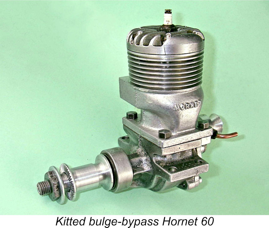
As far as I’m presently aware, this kit was released in the first half of 1949. My basis for this statement is the inclusion of a full description of the kit in an article entitled "Present Day Motors" by Edward G. Ingram which was published in the June 1949 issue of “Model Airplane News”. The central element in this kit was a new upper cylinder casting featuring a far larger exhaust stack and a Dooling-influenced bulge bypass which extended the annular width of the bypass passage at the transfer port location. Unlike the Dooling, the original Hornet's direct connection between the crankcase and the base of the bypass was maintained together with the use of piston ports as before. The main effect of the bulge at the top of the bypass was to extend the bypass further around the cylinder wall at the front and rear at transfer port level. To take full advantage of this, it was necessary for the owner to create two additional transfer openings, one each at the front and rear, bringing the total up from three openings to five.
The kit came with full installation instructions, including directions for creating the two extra transfer ports in the cylinder liner to take full advantage of the increased bypass capacity. The installation of this kit was quite credibly claimed by the designer to raise output to 1.22 BHP @ 18,000 rpm using suitable fuel with glow-plug ignition. While not matching either the Dooling or the Series 20 McCoy, this was still a relatively competitive level of performance which would certainly breathe new life into old Hornets! A more detailed description of this model may be found in my companion article on the tuned Hornets. The factory offered a service whereby they would install the kit on a customer's engine for a specified fee. However, it's significant to note that they never offered all-new engines assembled in the revised format. It's an entirely logical conclusion that the actual manufacture of complete engines by the company had ceased altogether by this time, hence the total reliance upon previously-existing engines to deploy these improvements. The Endgame
Based on the surviving examples which turn up from time to time, it would appear that a number of the conversion kits were in fact sold to die-hard Hornet owners. The kit was by no means ineffective - in fact, a kitted Hornet 60 powered the first model to exceed the magic 150 mph mark in Class D control line speed, thus breaking a record which had previously been established at 147 mph by a Dooling 61 powered model. However, this proved to be the Hornet's last gasp, since the Dooling and McCoy Series 20 opposition soon leapfrogged back past the Hornet's short-lived record, a situation to which the Hornet proved unable to respond.
There is no record of the number of Hornet Tiny-Mites built by the Snow family, but it's clear that Ray believed in giving his children ample hands-on opportunities to learn the racing business from the ground up at an unusually early age! I've been unable to find any authoritative information regarding the full extent of the Snow family's ongoing involvement with the sport. Racing in Fresno continued at the Kearney Bowl track until the end of the 1970 season, after which the site was purchase by the City of Fresno's redevelopment agency. They bulldozed the facility and constructed a housing complex and school on the property. 3847 Ventura Boulevard (now E. Ventura Street) was a vacant lot as of early 2012, while 3849 Ventura was occupied by a print shop and a sign-making business. Conclusion Ray Snow may be gone, but his Hornet engine remains alive and well today. These fine units were highly valued by their owners as well as being both very durable and rather too large to "lose". Consequently, a good proportion of those that were made still survive today, many of them in excellent condition. Original examples show up regularly on eBay and elsewhere at healthy but not unaffordable prices.
However, this situation came to an end in 2012, when Woody finally ran out of his fine replicas and had no plans to have any more made. At that point, his replica Hornets became prized collector's items in their own right and the original Hornets were freed from competition from retail sources. A full range of Hornet parts remained available for a time, but Woody’s death in 2018 marked the end of his invaluable services to the collector community. While some might dismiss the Hornet engines as failures given their ultimate inability to keep pace with the best of their competitors, I must say for the record that I disagree completely. No engine which remained at or near the top of the competition pile for a full decade can legitimately be viewed as a failure! Moreover, there's no question that the Hornet 60 and its predecessor, the A.C. Special, established the "classic" racing engine configuration which was to hold sway for a period of some 25 years or more. That in itself is no small achievement on the part of the designers and earns the Hornet a unique place in model engine history. The Hornet preceded the iconic McCoy 60 into the marketplace by several years and unquestionably exerted a strong influence upon Dick McCoy's design thinking in relation to the racing engines which made his name famous. I'm sure that Dick would have been the first to recognize the contribution made to his favorite branch of the hobby by Ray Snow and the Hornet engines! ___________________________ Article © Adrian C. Duncan, Coquitlam, British Columbia, Canada First published on MEN March 2012 This revised edition published here February 2024
|
 Here I’ll share an in-depth look at a respected and highly significant American marque which ushered in a new era in model engine design - the Hornet series from Fresno, California. Introduced in the late 1930's, these engines established the basic design pattern for the "classic" racing engine which was to dominate high-performance power modelling right through to the mid 1960's. As such, the Hornet may legitimately be seen as something of a milestone in model engine design terms, thus being well worthy of our notice.
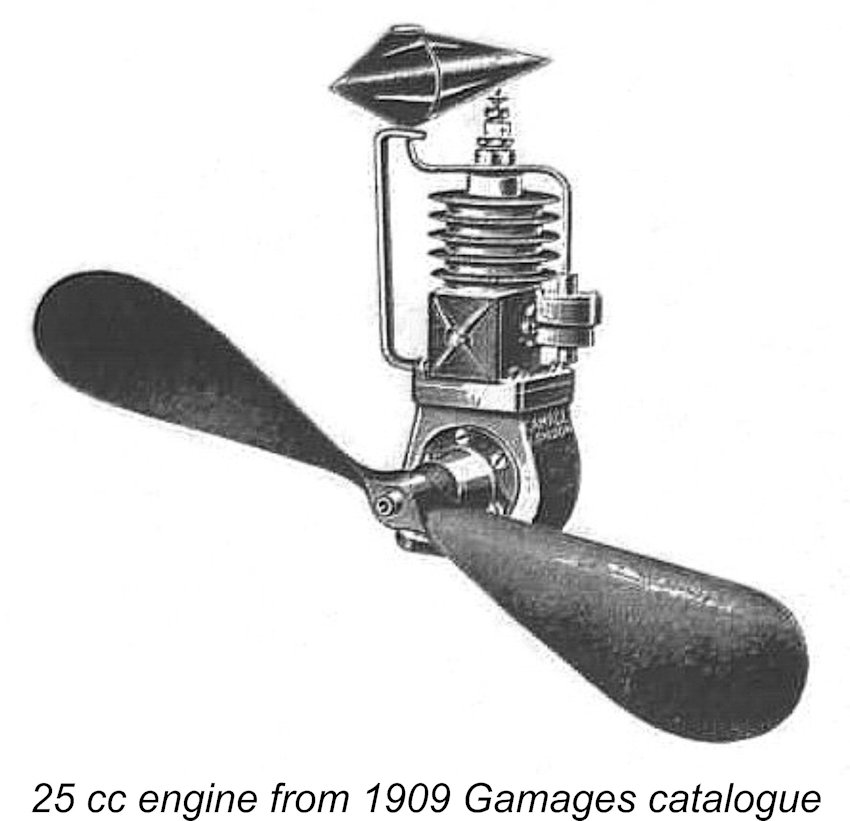 Although the British modeller
 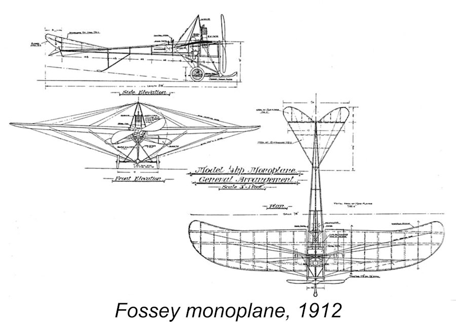 The first set of published plans of which I'm aware for a model expressly intended to be powered by a single-cylinder petrol engine appeared in Britain in the September 1912 issue of "Model Engineer". This monoplane design by J. and H. F. Fossey had a wingspan of 6ft. 6in. The original model had been featured at the 1911 Model Engineer Exhibition. The specified ¼ horsepower engine bore a marked similarity to the Gamages model mentioned above – it may even have been such an engine.
 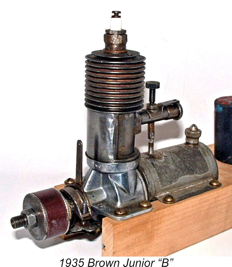 manufacture of model engines worldwide. The first dozen or so engines were made by Bill Brown in his home workshop, but by 1934 the 10 cc Brown Junior "B" was in full-scale production by Junior Motors of Philadelphia, Pennsylvania.
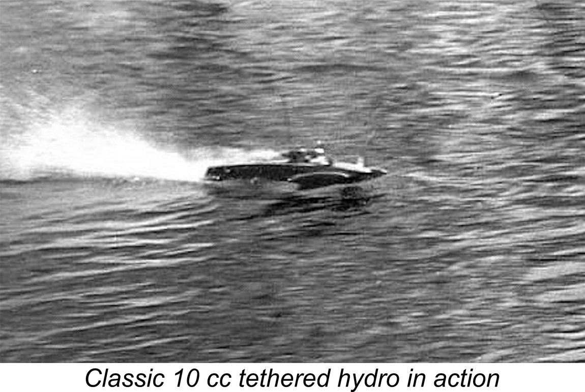 Accordingly, power model enthusiasts who were interested in all-out speed found themselves drawn towards other forms of power modelling such as tethered I/C-powered model car and hydroplane racing in which models remained at surface level (mostly!) and under restraint (usually!) during operation. In addition, the fixed path to which these models were confined by their tethers or rails allowed for accurate timing and hence speed measurement. Both of these performance-oriented branches of the hobby attracted an increasing following in the USA as the 1930's drew on.
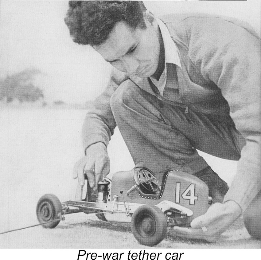
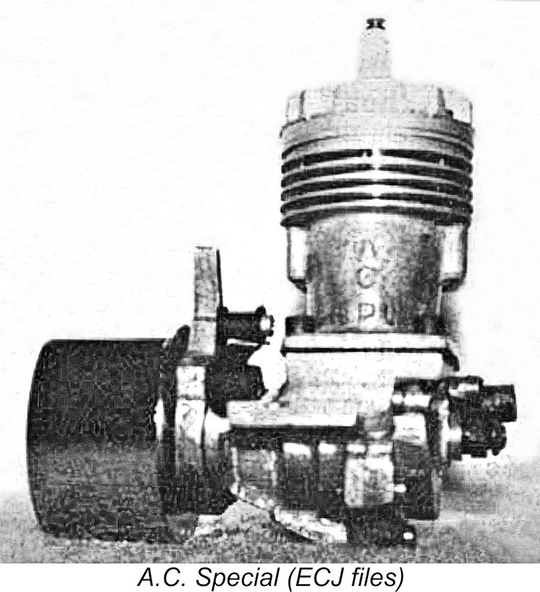 This engine was named the A.C. Special after the initials of its designers Anderson and Cave. It was an interesting and innovative design in a number of ways. It had a displacement of .607 cuin. and used spark ignition (then the only available option), rotary disc-valve induction, cross-flow loop scavenging, a ringed aluminium piston, a twin ball-race crankshaft and an automotive-style timer. Massive sand-castings were employed throughout. Sound familiar?!? Yes indeed, this was a pioneering example of what was to become the "classic" racing engine layout for much of the next three decades. The one point of departure from the classic racing engine formula was the fact that the main bearing housing was cast integrally with the crankcase rather than being incorporated into a detachable front cover.
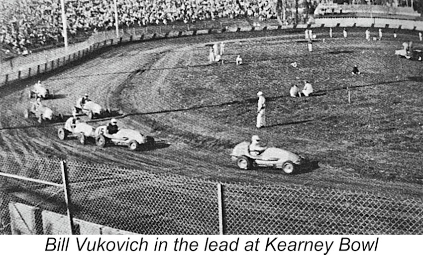 To address these issues, Messrs. Anderson and Cave went seeking a partner and found one in the shape of Ray Snow Jr. of Fresno, California. Ray Snow owned a machine shop in Fresno which catered among other things to the needs of the full-sized midget car racers who competed at the then-famous Kearney Bowl Speedway near downtown Fresno. These included the renowned "Fresno Flash", Bill Vukovich, who scaled the heights of full-sized car racing and was finally killed while leading the 1955 Indianapolis 500, an event which he had won the previous two years on the trot. Racing was a serious business in Fresno!
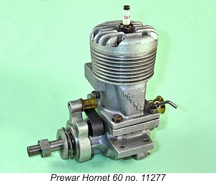 with Anderson and Cave. Moreover, he had the facilities and expertise required to manufacture model engines in quantity. A new company called Hornet Motors was accordingly formed in 1939 to continue the development and marketing of the A.C. Special. The revised model was manufactured at Ray Snow's machine shop, then apparently located in downtown Fresno at 1440 Fulton Street. The engine was marketed as the Hornet 60, reflecting the identity of its manufacturer. Fulton Street today lies in an area of downtown Fresno which is zoned primarily for retail, although the free-standing building at number 1440 is now occupied by The Downtown Church.
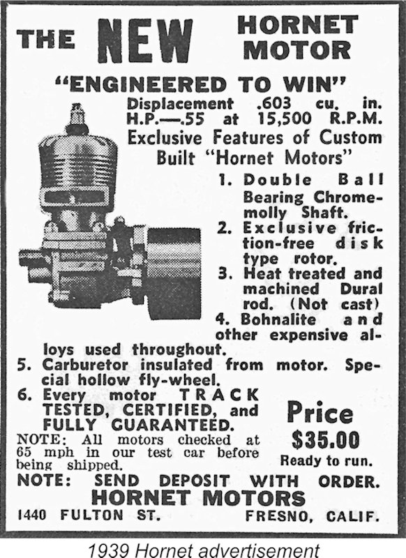 production contract with Ray Snow. However, it seems perhaps more likely that Anderson and Cave sold the design outright to Ray Snow, perhaps on a royalty basis for each engine sold. However this went, it's an indisputable fact that by the conclusion of WW2 Ray Snow had acquired full personal control over the development and manufacture of the Hornet design.
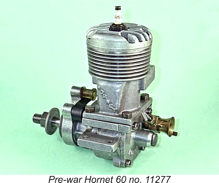
 The power output claimed in the advertisements for this initial variant of the Hornet 60 was 0.55 BHP @ 15,500 rpm - not actually all that impressive compared with what came later. Be that as it may, there's no arguing with success! The Hornet quickly became the motor to beat in 10 cc model car racing (Dick McCoy had yet to produce his first engine at this stage), also proving extremely effective in hydroplane service. Consequently, the engine soon began to draw a great deal of interest from the high-performance modelling crowd notwithstanding its very steep asking price of $35.00. This naturally encouraged Ray Snow to plan for increased production in addition to making a few more design improvements.
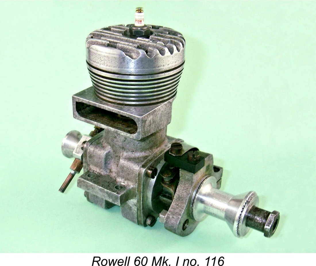
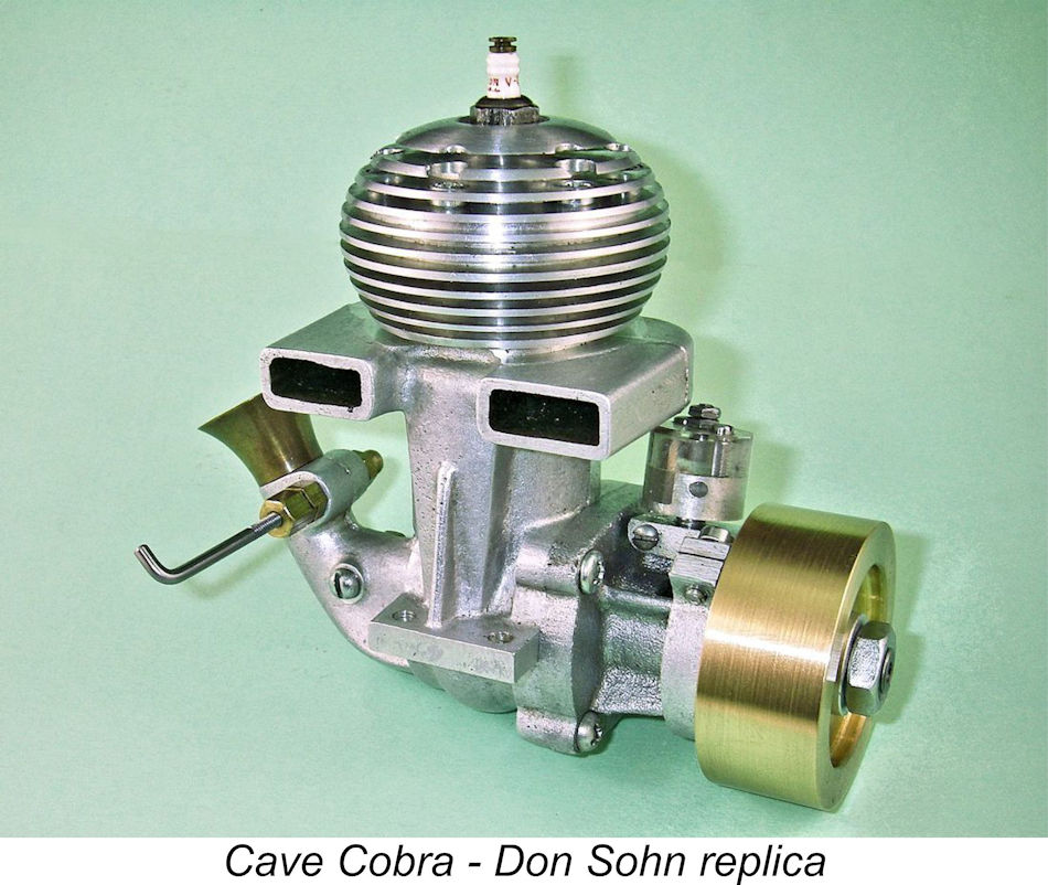 After WW2, the former Hornet Motors partnership was not resumed. Charlie Anderson seems to have disappeared from view altogether. Walt Cave founded Cave Model Engines on his own, producing the highly individualistic .604 cuin Cave Cobra car engine in 1946. Although a very fine product indeed displaying a number of innovative design features, this engine did not survive in the marketplace in the face of the Hornet,
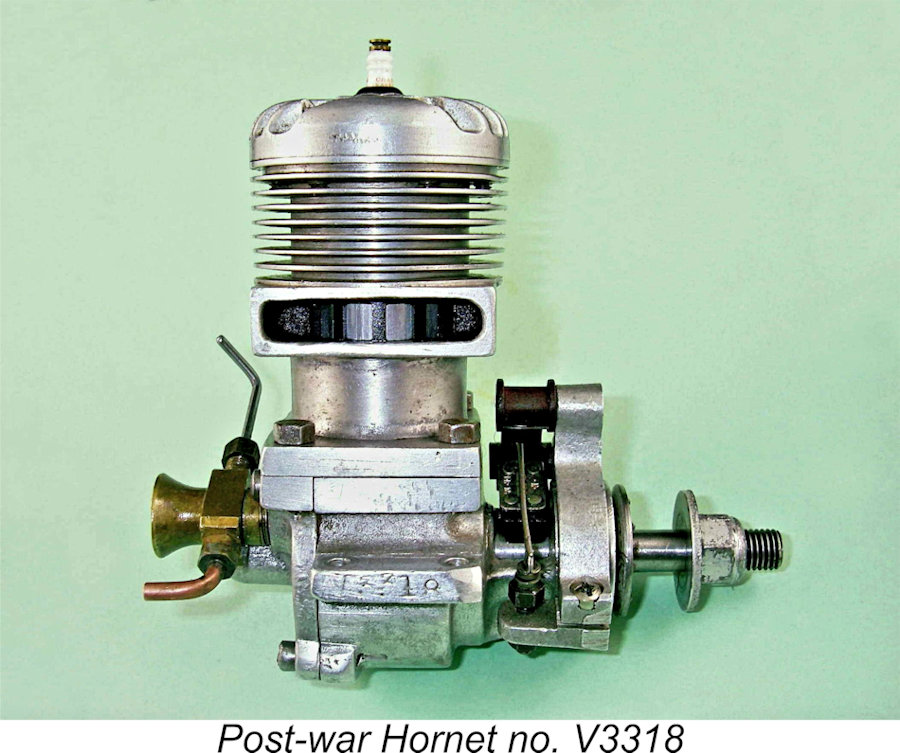
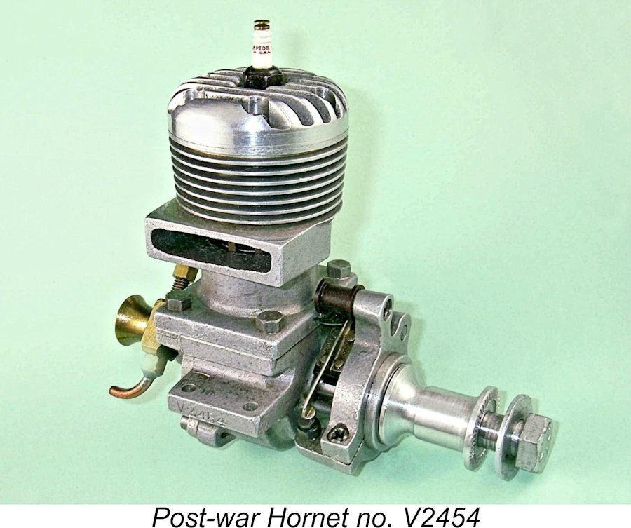 The Hornet 60-A retained the square-on-shaft method of prop driver attachment and extra-long shaft of the pre-war aircraft models along with the steel prop driver. Illustrated engine number V3318 typifies this set-up. However, this prop driver placed the airscrew inconveniently close to the timer and cylinder, causing many owners to fit their engines with aluminium bobbin drivers and steel sleeve nuts to facilitate mounting in a speed model. Illustrated engine number V2454 exemplifies this eminently practical approach.
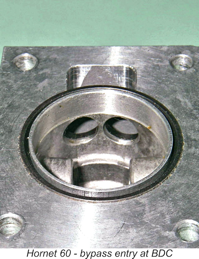 For the model hydroplane enthusiast, the Hornet was also made available in a 60-B format, with a flywheel which was specially tailored towards boat use. However, the engine was still intended primarily for model car applications, being offered for this service in its 60-RC form with a race car flywheel assembly. All models were constructed to the very highest standards, as surviving examples attest.
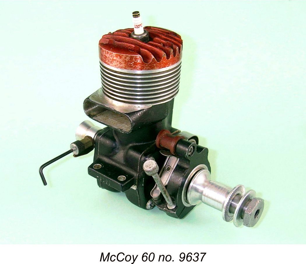
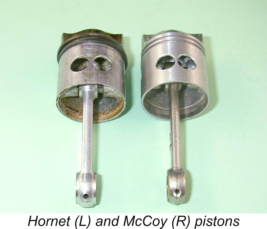 It's actually interesting to note that the Hornet piston appears identical in all respects to that of the McCoy 60 apart from the fact that the bosses were set higher up in the McCoy piston to accommodate a longer rod with a consequently lesser swing angle. Indeed, the rings used in the two designs are directly interchangeable, probably originating from a common source. This underscores the strong design influence which the Hornet exerted upon Dick McCoy when he was designing the McCoy 60.
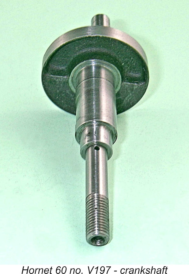
 The consequence of this is that an aero shaft will not fit an early Hornet which was originally intended for car or boat work, nor can it be made to fit through a bearing change. The aero and car shafts in later models are interchangeable, however. This is a point of which to be aware when considering the purchase of a Hornet for a specific purpose. A car or boat Hornet can of course be used in aero service, but this will require that a custom prop driver using a split collar mounting be made.
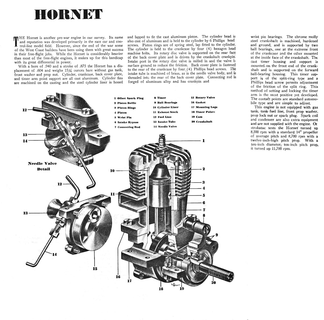 A review of the Hornet 60 appeared in
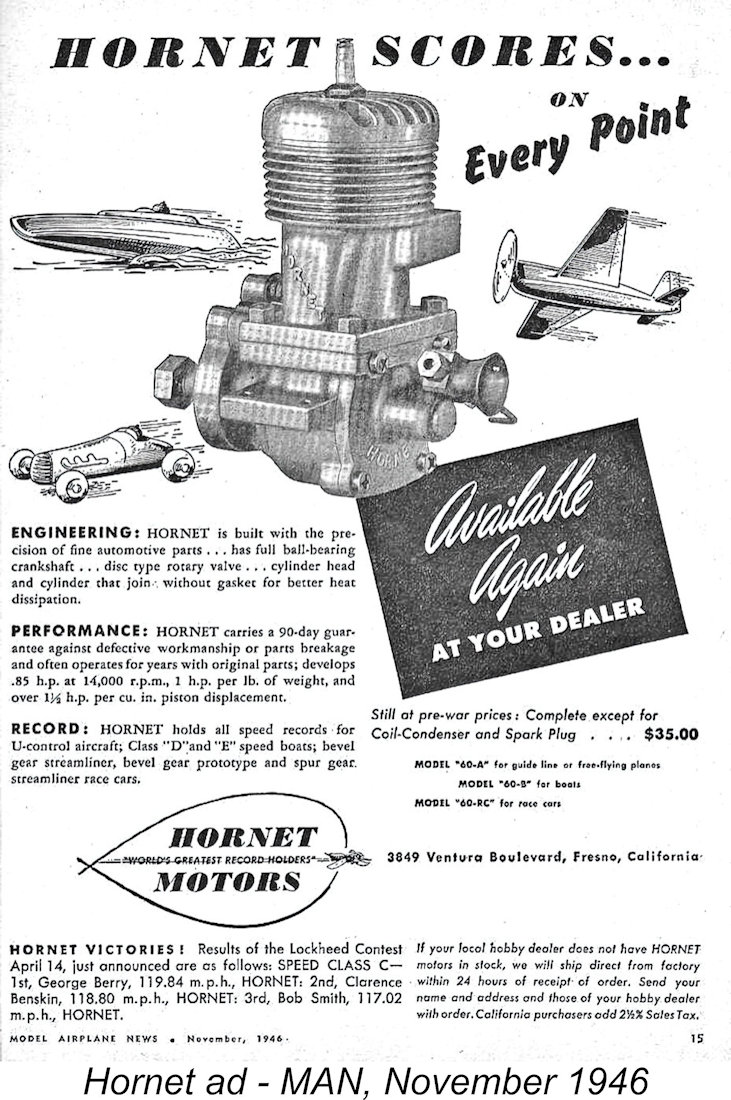
 For the first few years of the post-war period, the Hornet managed to hold its own without significant further development. The McCoy 60 was now in full series production by the Duro-matic Products Company of Hollywood, California, but the Hornet performed pretty much on a par with the McCoy at this stage and there was little other commercial competition at the time. The McCoy and the Hornet were "the" engines to have in all forms of 10 cc competition as 1946 advanced into 1947.
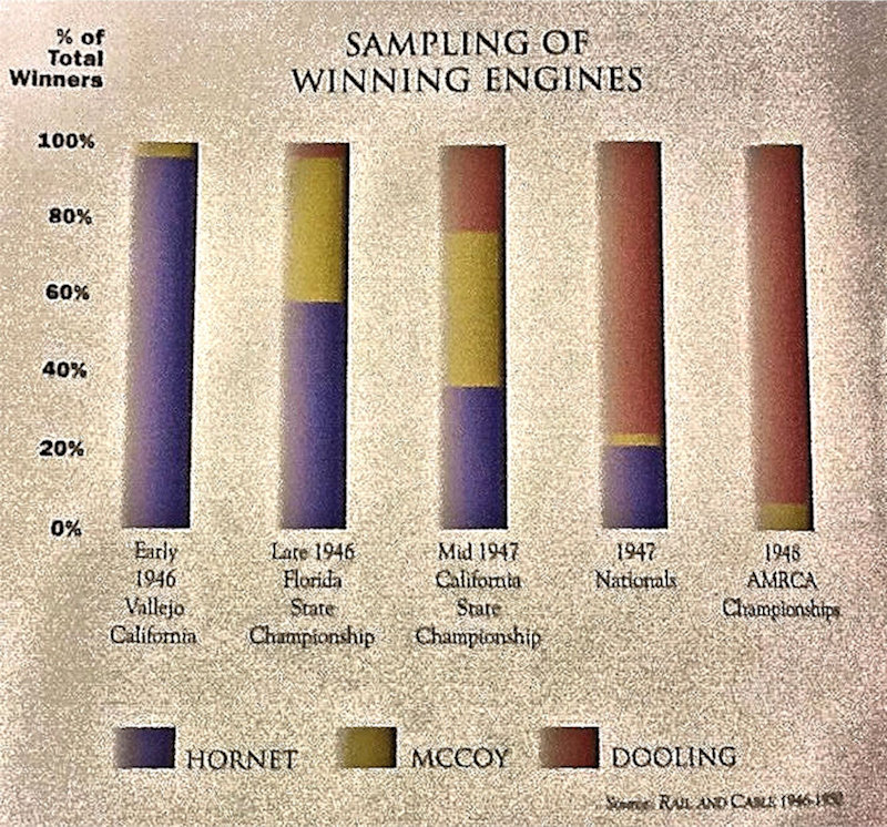
 Fortunately, the Hornet was very adaptable to glow-plug operation, as my own tests have confirmed conclusively. Starting qualities are outstanding and running is very smooth (albeit LOUD!), with excellent needle response and adequate fuel draw for operation on suction feed. The engine's very sturdy construction enables it to absorb the additional operational stresses with ease. And such sturdiness was very necessary once people started pouring fuels containing proportions of nitro as high as 60% into the engines!
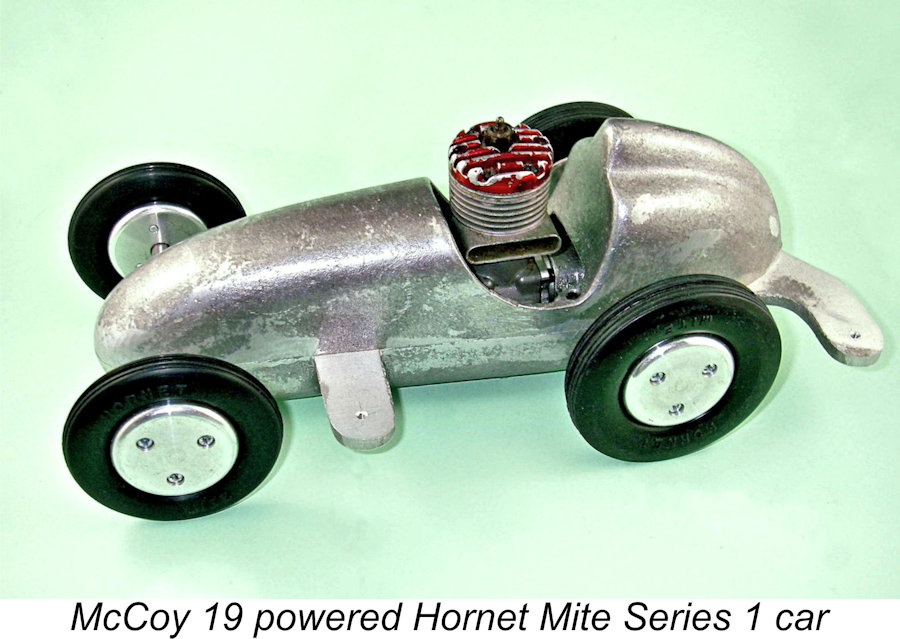 A number of companies were already manufacturing highly competitive car models for the .60 cuin. engines of which the Hornet was an example. Accordingly, Ray Snow decided to challenge the market with a car to meet the burgeoning "Mite" class. This category was intended as a lower-cost alternative for would-be model car racers, being restricted to engines of less than .200 cuin.
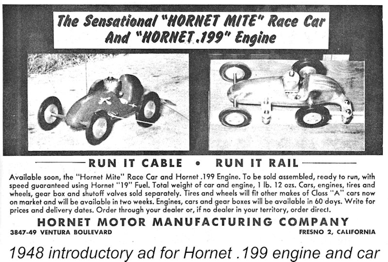 In general terms, the Hornet .199 followed the design layout of the Hornet 60 quite closely. It had the same mixture of rear disc-valve induction, cross-flow loop scavenging, twin-ringed alloy piston and twin ball-race crankshaft which was by now recognized as the "standard" racing engine formula of the day. Since it appeared in 1948 just as the glow-plug tide was rising, it was understandably offered only as a glow-plug model.
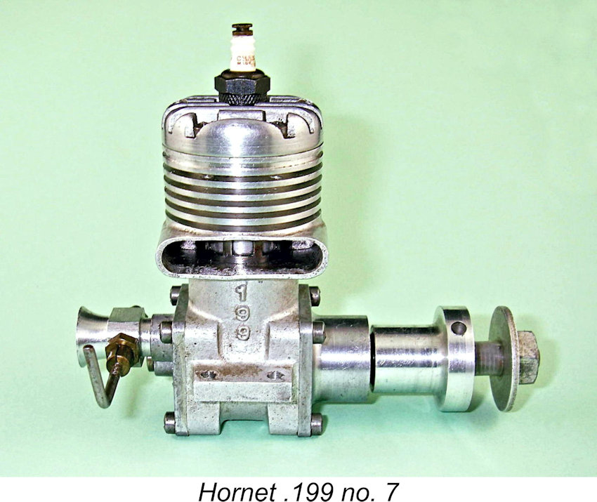 assembly was now machined from aluminium alloy rather than brass and was made in a single piece, being secured by a grub-screw rather than being threaded into the backplate. Otherwise, the two designs were basically similar.
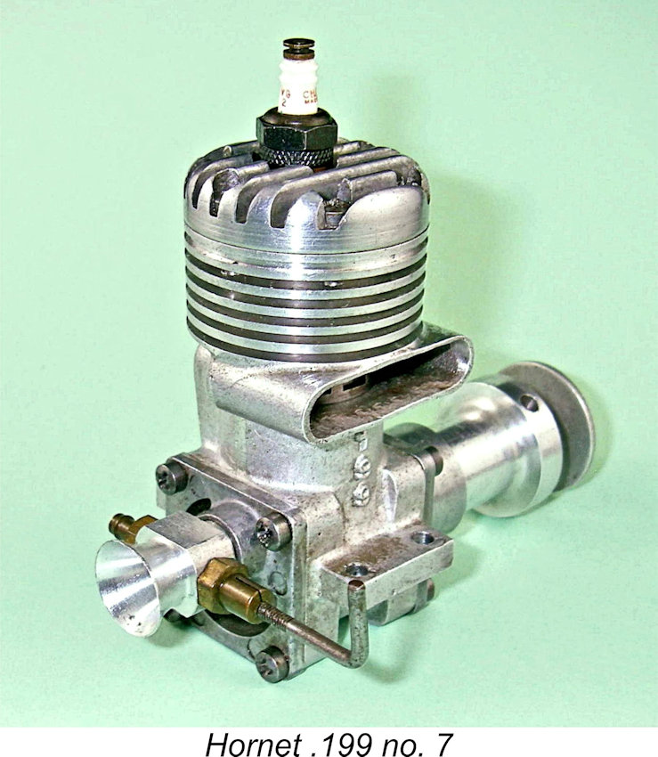
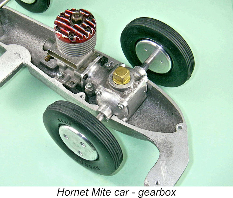 gearbox in close proximity to the main crankcase, thus reducing the power-train's axial length to facilitate mounting in a car. Note that no flywheel was employed when using one of these gearboxes - presumably the wheels were considered to serve that function despite the 2½ to 1 reduction. For aircraft use and bench testing, an extended bobbin prop driver was provided.
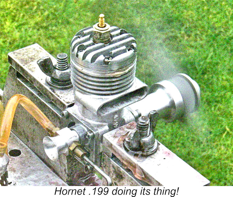 The Hornet .199 engines carried serial numbers. The only two examples of my personal acquaintance are my own engine number 7 (originally from the collection of my late friend Ted Enticknap) and engine number A136 which sold on eBay in 2011 (for well over $500!). I'm not sure about the significance of the A prefix. Tim Dannels reported that fewer than 200 examples of the Hornet .199 engine were manufactured. Consequently, this is unquestionably one of the least commonly-encountered Hornet models today.
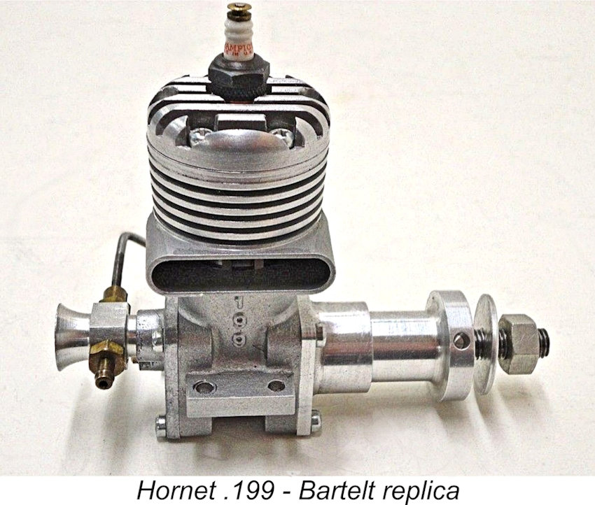
 It would appear that the failure of the "Mite" car project and the Hornet .199 combined with the increasing performance shortfall of the Hornet 60 may have convinced Ray Snow that his economic future lay in areas other than model car and model engine manufacture. Certainly, there were no moves towards the development of an all-new .60 cuin. model, which was probably what was really required to stay in the game. However, there was another route open, and Ray took it. He developed a conversion kit for the existing Hornet 60 to bring it more or less up to par with the emerging competition.
 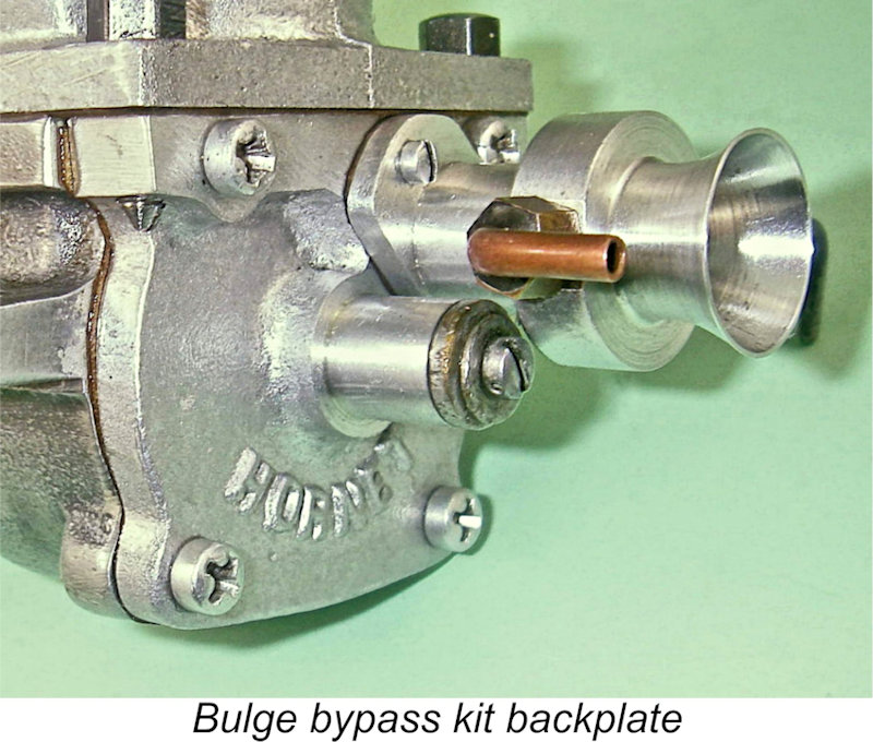 Along with this went a revised lightweight piston. The kit was completed by a modified backplate and carburetor assembly. The revised venturi section was secured to the modified backplate using two screws, thus eliminating the installation problem formerly caused by the screw-in assembly and permitting the machining of the component from aluminium alloy as a single piece. It had a bore of 0.375 in. as opposed to the 0.325 in. of the standard component.
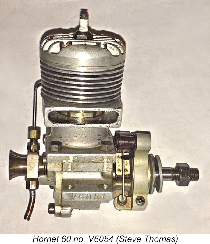 At present I'm unable to provide a credible estimate for the number of post-war Hornets that were manufactured in total - my serial number sample is far too small. All that I can say is that the highest serial number of my present acquaintance is illustrated engine number V6054. The fact that I'm also in direct contact with engine number V167 appears to confirm that the post-war numbering sequence started at V1 or possibly V100. These two numbers combine to suggest that at over 6,000 examples must have been made at the very least. It's not unlikely that there were quite a few more. I'd be most grateful to any reader who can authenticate any serial numbers which extend this range.
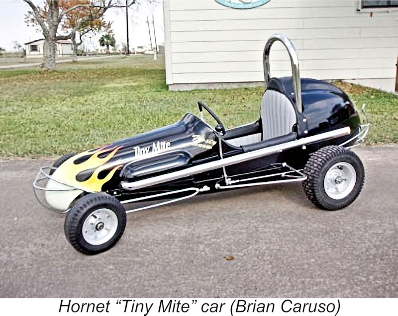 Sadly, it was a case of too little, too late, and the Hornet model engine enterprise seems to have disappeared altogether by the end of 1950, leaving the Dooling and McCoy to contest the field unchallenged. In any case, by this time Ray Snow's attention had seemingly shifted. His activities had by no means been confined to the manufacture of model engines, since he retained an ongoing interest in the full-sized midget car racing scene which continued to flourish in Fresno. This led eventually to him acquiring the rights to the manufacture of the quarter-midget "Tiny-Mite Sprint Car" from its designer and original constructor Bud Gregory of Los Angeles. The quarter-midgets were (and still are) reduced-scale open-wheel sprint cars with 7.5 cuin. (125 cc) engines intended to serve as an entry-level class for young drivers coming into oval racing - more or less equivalent to the go-karts of today for budding road racers.
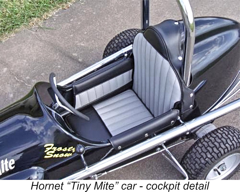 Ray changed the name of this neat little car to the "Hornet Tiny-Mite" and carried right on making it at his Fresno machine shop. Interestingly enough, Ray was soon able to involve his three children, who ranged in ages from 8 to 18 at the time. The eldest son worked with Ray on the fabrication and assembly of the cars, while the middle child, a daughter, served as the bookkeeper and was responsible for parts and inventory management. The youngest son, nicknamed "Frosty" Snow for none-too subtle reasons, was the only one who met the driver age limits for the quarter-midget class (5-16 years) and he accordingly became the test driver - note his name on the cowl of the illustrated restored example of the Hornet Tiny-Mite.
 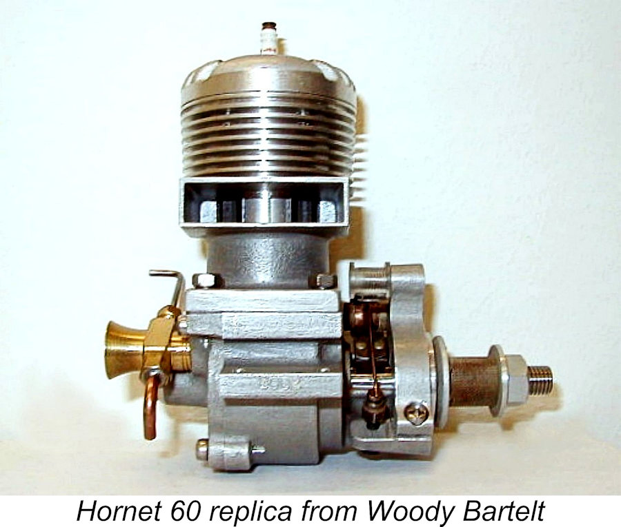 For some years the price of original Hornets was kept under control to no small extent by the availability of beautiful reproductions from Woody Bartelt. These were made in Ukraine to Woody’s specifications. Both standard and bulge bypass variants were replicated. In addition to the complete engines, Woody offered a full range of spare parts, all made to the very highest standards. Using Woody's fine components, any Hornet could be fully restored even if one lacked the capacity to make the required parts for oneself. My own original bulge bypass model sports one of Woody's replica timers.
 | |