
|
|
The Thuella “Favoriet” 2.47 cc Diesel
This attractive-looking and compact motor was designed by a well-known Dutch modeller of the day named Hans Brinkman, a resident of the famous Dutch university city of Leiden. It was marketed by Brinkman under the company name of “Thuella Miniatuur Motoren”. The stated company address was Koniginnenlaan 67 in Leiden. All sources agree that the engine didn't attract sufficient sales attention to warrant its continued production over the long haul. Apparently some 100 examples at most were produced in all during 1960 and 1961, with a few more examples being assembled later from mostly original components. We will be considering the possible reasons for this short production lifespan as we proceed.
I also wish to acknowledge the invaluable contribution of Dutch model engine expert Tom ten Brink. Tom knew Mr. Brinkman personally and was involved in the production of the very last examples ever made, one of which is featured as the focus of the present article. His first-hand insights contributed greatly to my understanding of the facts. Thanks, Tom! With these acknowledgements having been gratefully recorded, let’s get on with the story....... Commercial Model Engine Production in the Netherlands up to 1960
The NOVA 1 was an extremely long-stroke engine having bore and stroke dimensions of 16 mm and 22 mm respectively. It weighed a hefty 250 gm (8.82 ounces) complete with airscrew. With its long conrod, it was a very tall unit indeed! However, it evidently ran very well. As far as I'm aware, the NOVA 1 was never put into series production, instead being presented by its designer as a subject for home construction. Mr. van Leeuwen published a detailed article describing the engine's construction in considerable detail. This article appeared in two parts in the March and April issues of the Dutch magazine "De Modelbouwer" (The Modelbuilder). The accompanying illustration is taken from that article, of which an English translation may be read here. The NOVA 1 is among the home construction projects included in the Motor Boys Planbook which may be accessed elsewhere on this website. A number of fine examples of the engine have since been constructed by various talented individuals, including Swedish reader Olle Eriksson, whose rendition was featured on the late Ron Chernich's wonderful "Model Engine News" (MEN) website.
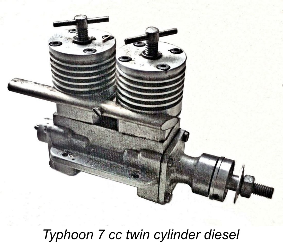
The first commercial model engine range to appear in the Netherlands following the conclusion of WW2 was the Typhoon marque from Amsterdam. This series of high quality model powerplants was the creation of Jan Veenhoven, who established a workshop at Keizeragracht 372 in Amsterdam. The first Typhoon model appeared in 1947. It was a 4 cc fixed compression plain bearing crankshaft front rotary valve (FRV) diesel featuring a sandcast crankcase with an updraft venturi. This was designated the Typhoon Mk. 1 model. Veenhoven carried on from this point, producing a surprisingly varied range of model diesel and glow-plug engines ranging in displacements from 2.5 cc up to 10 cc. A notable product which attracted some attention from outside the Netherlands was his 5 cc Mk. 4 racing glow-plug unit. A diesel version of this design appeared a little later. Veenhoven's excellent 2.5 cc R250 twin ball-race contest diesel also commanded international respect. But perhaps Veenhoven's finest effort was his superb 7 cc twin cylinder rotary valve diesel, of which some 30 examples were made between 1958 and 1960. His 5 cc twin ball-race diesel based upon the design of the Mk. 4 As of 1960, Veenhoven was still offering his R250 and 5 cc twin ball-race diesels and (in very limited numbers) the 7 cc twin. At this point he was successful in arranging for O. F. W. "Peter" Fisher’s Performance Kits company in England to act as his British agents. This expansion of his market base enabled him to remain in production until 1963, at which point all Typhoon production ceased. A detailed article covering the full Typhoon range will appear on this website in due course. Typhoon production was thus still ongoing as of 1960, when a new manufacturer from the Netherlands put in what was to prove to be a rather brief appearance. This was Hans Brinkman with his Thuella “Favoriet” 2.47 cc diesel which forms our main subject. Brinkman was a then well-known Dutch aeromodeller living in Leiden. At some point he became confined to According to Tom ten Brink, Brinkman did not have a factory as such, instead arranging for most of the components to be machined by others. Apart from developing the original design and making the die for the pressure die-cast crankcases (which were produced by others), his role was confined to machining the backplate components, assembling the engines and marketing them. The address on Koniginnenlaan (King's Avenue) in Leiden was very likely his home address. Model engine manufacture was not Brinkman's only commercial involvement with the model trade. He also marketed a line of R/C equipment under the "Poly-Prop" brand name. An example of one of his trasmitters appears in the above illustration. Having now seen the Favoriet come into existence, let’s take a closer look at the engine. The Thuella “Favoriet” - Description
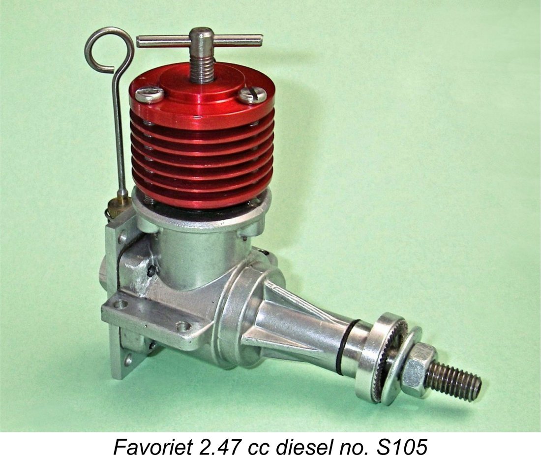
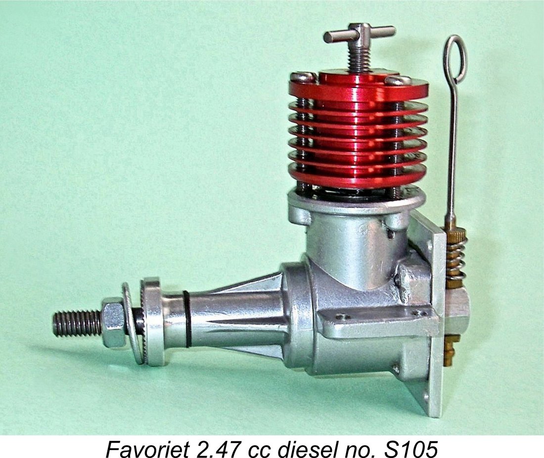
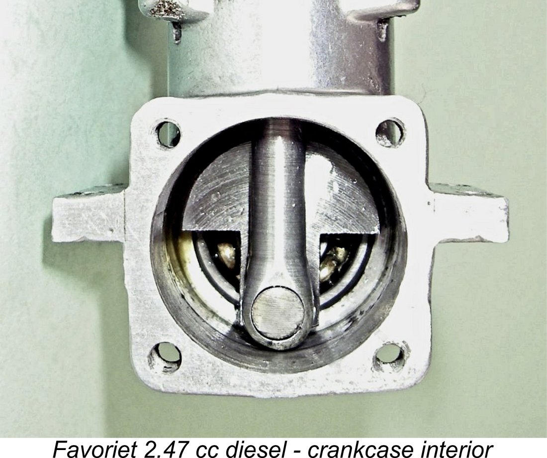
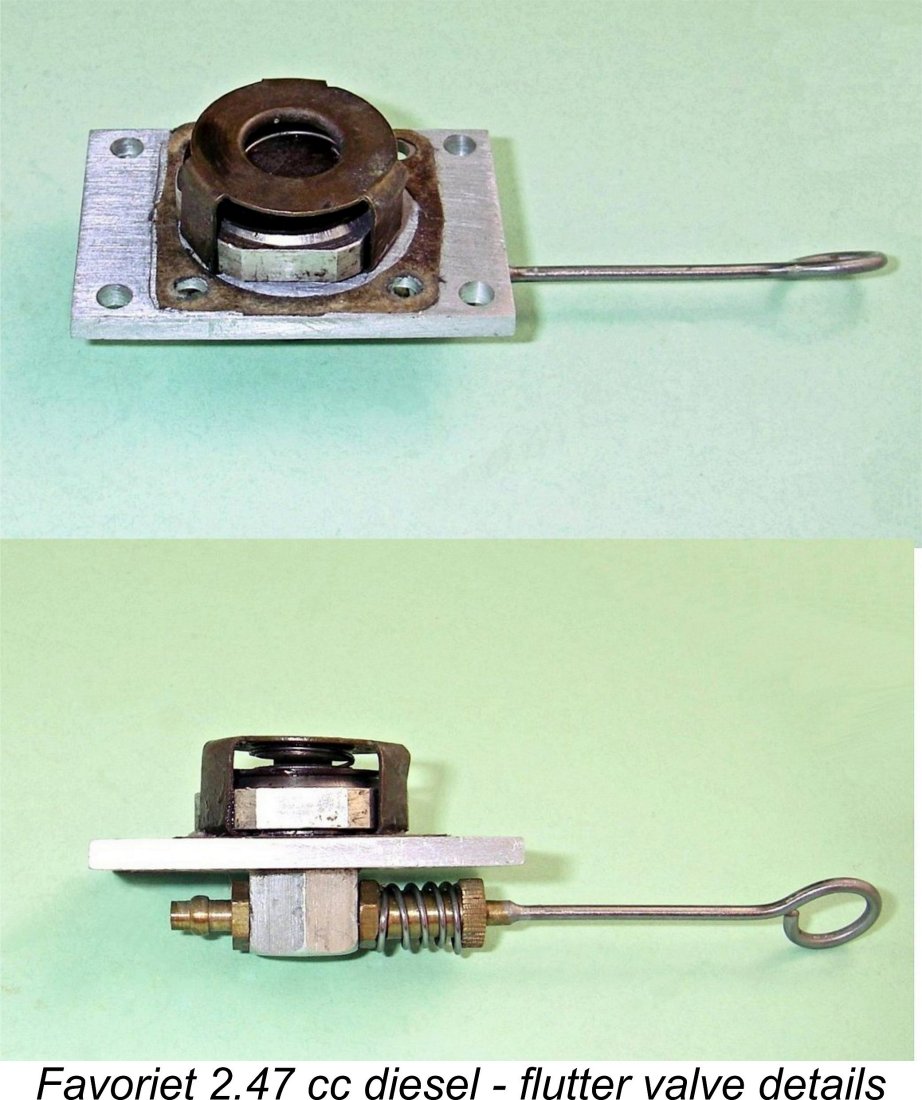
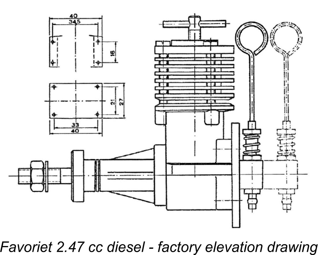
Beginning with the tale of the tape, the engine’s bore and stroke dimensions are a little unusual - the designer has selected a slightly longer stroke than the standard Continental figure of 14 mm with a 15 mm bore. It would appear that he was going after good torque development at lower speeds - a logical objective given the type of cylinder porting employed. The bore and stroke of the Favoriet are 14.75 mm and 14.45 mm respectively for a displacement of 2.47 cc (0.1507 cuin.). The engine weighs a checked 154 gm (5.43 ounces), although the manufacturer claimed a weight of only 145 gm (5.11 ounces). Either figure is relatively light for a single ball-race diesel of this displacement. The engine is built up around a cleanly-produced pressure die-cast light alloy crankcase which incorporates the main bearing housing in a single unit. The hardened nickel-chrome steel cylinder is a drop-in component which is secured using three long bolts passing through the red-anodized light alloy cooling jacket to engage with tapped holes in the upper crankcase casting. The jacket bears upon the engine's cylinder’s port belt, which sits in a shallow recess formed at the top of the crankcase. This ensures both Both the piston and contra-piston are machined from fine-grained cast iron. Three exhaust ports and three transfer ports are formed as slots sawn into the cylinder. By 1960 this had become a rather anachronistic design feature. With this type of porting, no overlap is possible, unavoidably resulting in a relatively short transfer period. The bypass passage is formed by the 360 degree annular gap between the lower outer cylinder wall and the interior wall of the upper crankcase, as mentioned earlier. Actual cylinder port timing figures for the Favoriet are: Exhaust opens 110 degrees ATDC (period 140 degrees) Transfer opens 135 degrees ATDC (period 90 degrees) There is no sub-piston induction. The figure for the exhaust is quite rational, but the transfer opening The flat-topped piston drives the crankshaft through a very sturdy fully machined light alloy conrod. The fully floating gudgeon (wrist) pin is made of chrome-vanadium silver steel. The one-piece nickel-chrome steel crankshaft is solid throughout. The crankweb is heavily counterbalanced. The shaft runs in a single ball race at the rear and a bronze bushing at the front. A quality touch is the inclusion of a nylon thrust washer between the alloy prop driver and the front of the main bearing housing to limit crankshaft end float. Others should have copied …….! The engine uses a flutter valve induction assembly of rather unusual design. The closest parallel that I can think of is the arrangement utilized by the FROG 149 Vibramatic of The actual flutter valve is a thin circular plate of a stiff non-metallic Tufnol-like material which seals against the rim of the valve’s internal cavity and is held shut by a low-tension coil spring. This spring in turn is retained by a stamped and bent brass keeper which clips onto the inner element of the induction system at three points. Hopefully the attached images make this arrangement clear. It should be readily apparent that the design inescapably gives rise to a larger-than-ideal crankcase volume. The flutter valve appears to be one of the weak points in this engine’s design. During his testing of this example following its refurbishment, Peter Valicek found that the operation of the valve was somewhat uncertain. It was found to be very difficult to establish a stable running condition, particularly at the higher speeds. Peter tried his own example of the engine, finding that it exhibited similar behavior, albeit to a somewhat lesser extent. Peter spent many hours trying to find a flutter valve configuration that worked well. He made a somewhat lighter valve disc and also tried a series of less powerful springs. He even tried installing a spacer ring to limit the maximum lift of the disc off its seat. In the end, he settled for his replacement lightweight disc without the spacer ring but with a somewhat lighter spring than the one originally fitted. With this combination, the engine proved to be easy to start and a very good runner at low and mid-range speeds. At the top end (13,000 + rpm), the needle setting remained very critical, but when the sweet spot was found the engine performed very well. I feel that the application of sub-piston induction might have done much to improve both the engine's output and its running characteristics. In my personal opinion, the use of sub-piston induction in a reed or flutter valve design is theoretically almost a necessity if maximum performance is to be achieved. Even the best reed valve is inherently more restrictive than a fully-open rotary valve, hence benefiting greatly from the assistance provided by sub-piston induction. Perhaps even more importantly, the feature has the great advantage of "releasing" the reed from crankcase pressure effects well before top dead centre is reached, thus giving the reed plenty of time to snap back into place on its sealing annulus before the sub-piston induction closes on the power stroke and crankcase pressurization begins. The German makers of the Taifun reed valve engines certainly used this arrangement to very good effect. Since the backplate mounting holes are arranged in a perfect square, the rectangular backplate can be installed either vertically (as illustrated) or horizontally. In the vertical position the engine can be beam-mounted using the lugs formed at the sides of the crankcase. In the horizontal orientation, the backplate serves as a radial mount. The promotional literature made much of this flexibility. A conventional brass spraybar having two opposing jet holes is used in conjunction with a coil spring-tensioned needle of notable length. The needle itself is unusually soft and easily bent. According to Tom ten Brink, the needle is a modified mannequin needle of the type used in clothing shops for fitting clothes properly to the mannequins. Although a bit large, it fitted well enough, so Brinkman used it! There were precedents - manufacturers such as Gordon Burford in Australia and Mills Brothers in England also used fabric needles of various kinds.
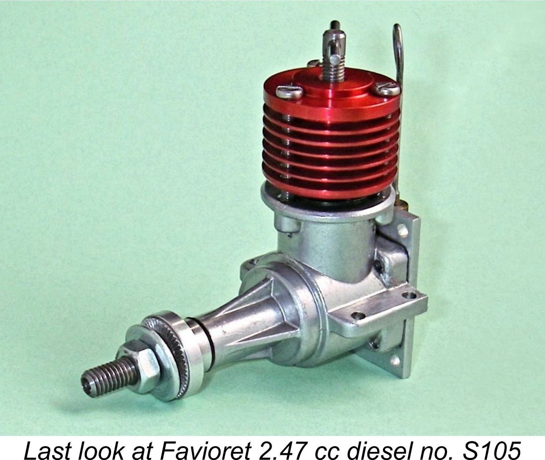
All the engines bore serial numbers which were neatly stamped onto the backplate beneath the intake. The numbers all appear to bear the letter S followed by a one, two or three digit number indicating the engine’s position in the production sequence. The only confirmed numbers of which I am presently aware are S67 (Fisher), S93 (Peter Valicek), S94 (Jim Dunkin) and S105 (my own example). In his 1977 “Collector’s Guide to Model Aero Engines”, O. F. W. Fisher claimed that around 150 examples were produced in total, all of them in 1960-61, but this estimate appears to be high - the true figure seems to have been around 100. The engine is consequently very rare today. At the time when the manufacture of the Favoriet ceased, a number of unused original components remained on hand, including a handful of crankcases. Prior to Brinkman's death in the late 1990's, these components were acquired by Tom ten Brink, who arranged for them to be built up into complete engines with the assistance of Mike Crisp in England. Mike and Tom continued the known serial numbering sequence without a break. My own illustrated example is one of these latter-day units. It bears the serial number S105 and was apparently the last example completed. It thus appears that the total number of engines produced was 105 - somewhat less than Fisher's estimate. The general quality of construction of my example is very high - well up to the best standards then prevailing for commercial model diesels. However, bringing it to that state required considerable intervention by Peter Valicek, as mentioned earlier. As originally assembled, the bore taper was very much less than optimal, while both the conrod bearings and the crankshaft ball race were poorly fitted and finished. Peter corrected all of these faults, also carrying out the previously-noted experiments to optimize the flutter valve. None of these difficulties can be charged to Brinkman, since he did not assemble this example. Following its refurbishment, the piston fit in this unit remained a bit on the tight side, but a proper break-in would cure that. Given the use of very suitable materials throughout, I would expect the Favoriet to give excellent service over the long haul. The Favoriet in the Modelling Media
“This new engine was designed and manufactured by the well-known model builder J. Brlnkman from Leiden. A very large dose of optimism must be needed to come up with a new brand of engine in a displacement category in which there is already great competition. In all honesty, one can already buy all kinds of 2.5 cc engines in our coastal communities, and good ones at that. The only way to successfully enter the market in competition with these models is to supply a product that in addition to having a long life, by which we mean a low rate of wear, may also have innovative features which are improvements on existing designs. After examining and discussing this new engine extensively and also flying it, we can say that it meets the above requirements. The innovative feature is the backplate, which serves as a rear crankcase cover, as a firewall mounting plate and as a mounting for the flutter valve housing and venturi tube. The latter component can be mounted in any desired position. The short venturi tube is used for mounting the engine on beam mounts, so that a short installation length is obtained. The materials used are the best that are currently available so that the engine, which is rather stiff when new, will have a long service life after a good running-in period. The engine falls in the middle class in terms of performance, so we think this engine is well suited for control line aerobatics, combat, general purpose free flight and radio control. Just a note for the owners or future owners of this engine - the re-mounting of the back plate following any realignment must be carried out with the utmost accuracy, especially the insertion of the four slot-head Starting this engine is simply a pleasure. Fill the fuel line, choke a few times, administer a small exhaust prime and flick the piston against compression. This does not even have to be done particularly energetically because the piston/cylinder fit is so good. Presto - the engine starts! Just one more tip - like any other engine, this one should be well warmed up before launch. With the Favoriet this takes a little longer than usual due to the engine’s robust construction. If one does not pay attention to this point, the chances are that the engine will end up running in the air with excessive compression or too rich a mixture, which is good for neither the engine nor the model’s performance. Unfortunately, we were not able to measure the power output and the associated speed, so we provide you with the data obtained from the manufacturer.” This review isn’t particularly informative, but I can confirm on the basis of hands-on experience that the countersunk slot-head backplate screws are indeed a bit challenging to get started true to the threads in the crankcase - they are very short, and the clearance holes in the backplate are too short to align them properly. I can see that it wouldn’t be too hard to get one of them cross-threaded. Socket-head screws would certainly improve the situation by allowing the precise alignment of the screws when being started into their tapped holes. The review also confirms my assessment that the engine is set up rather tight, hence requiring a proper break-in. The Favoriet was also the subject of some relatively extensive commentary in O. F. W. Fisher's well-known book "Collector's Guide to Model Aero Engines". However, Fisher's text adds nothing of importance to what has already been summarized above in the present article. The Favoriet on Test
As stated earlier, my example had been assembled by Mike Crisp and Tom ten Brink from original components which had to be used just as they were. The engine had a few issues as delivered, as mentioned earlier. The main bearing felt a bit rough and the conrod bearings were rather loose. In addition, the piston was a poor fit. My mate Peter Valicek fixed all of these issues, also spending some time optimizing the reed valve. Following his intervention, the engine was in perfect condition, all ready for testing. Despite Peter's greatly-appreciated efforts, the engine remained a little tight around top dead centre. This made it necessary to subject the unit to the full break-in procedure for ferrous piston/cylinder assemblies set out in my companion article on that subject. The engine had done some running in Peter''s hands, but felt as if it needed more. I didn't want to take any chances with it. Set up in the test stand with an APC 9x6 prop fitted, the engine confirmed by "feel" that it was undoubtedly in need of a full break-in. Using an oily break-in fuel, I proceeded to give it just that. I soon found that while the engine was easy enough to start, it invariably needed a small exhaust prime for dependable starting, just as noted in the "AVIA" review. Choking alone did not produce any result other than to flood the crankcase if carried to excess. A couple of choked flicks followed by a prime was the correct approach. Given this treatment, the engine proved to be a very prompt starter, once again just as characterized by the "AVIA" tester. Its only noteworthy vice was a tendency to start backwards on the smaller-diameter propellers - a common issue with atmospherically-controlled induction systems.
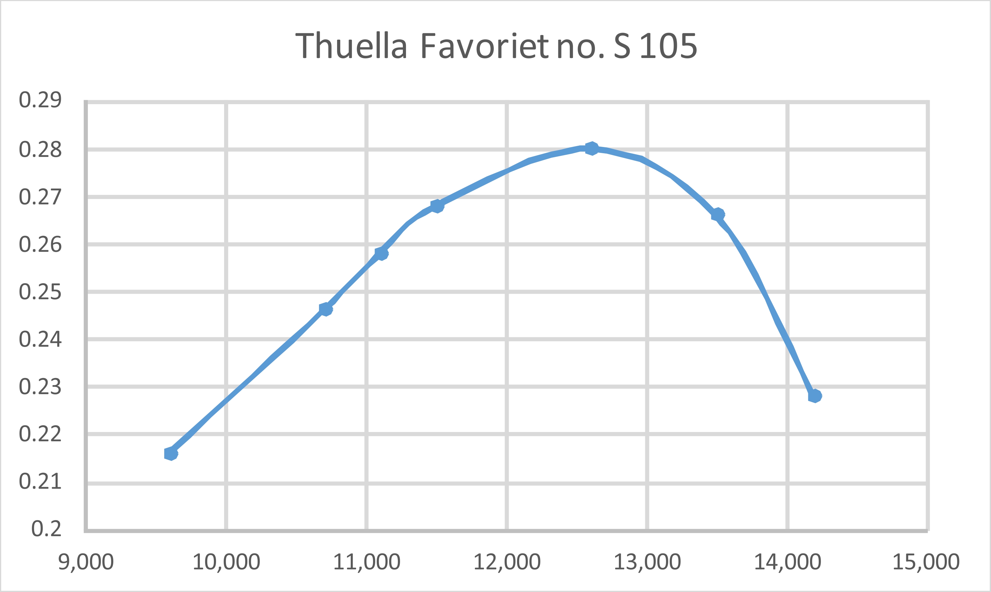
The reason for this behavior is that the operating cycle of a flutter valve (both timing and opening amplitude) is entirely controlled by pressure fluctuations within the crankcase. The magnitude and timing of these pressure fluctuations inevitably changes with engine speed. Unless the setting is already at or very near the peak, any needle valve adjustment generally changes the engine speed somewhat, hence modifying the operating cycle of the flutter valve. It takes a few seconds for the operating cycles of the engine and its flutter valve to re-harmonize at the new speed. Other flutter valve designs such as the FROG 149 Vibramatic display identical characteristics. Despite this issue, the best running setting was reasonably well defined, hence being easy enough to establish, although it did take a little time and patience to The engine ran very smoothly indeed once correctly set, but did seem to get quite hot initially. On the 9x6 prop it was necessary to reduce compression somewhat as the engine warmed up. The tight piston fit at top dead centre doubtless contributed to this by generating a considerable amount of excess frictional heat. I expected this to become less of an issue as the engine built up some more running time. I put on 30 minutes in 5-minute runs, leaning out at the end of each run and then allowing complete cooling before going for a re-start. The logic behind this approach is fully explained in my separate article on breaking in a ferrous piston model engine. At the end of this period the engine felt much better as far as the piston/cylinder fit went, leaving it feeling about as ready for testing as it was ever going to be - I didn't want to wear it out breaking it in! Switching to a more powerful fuel with reduced oil content and more kerosene, I proceeded to take speed readings for a representative set of calibrated airscrews. I continued to allow complete cooling between runs in order to increase the number of full-range heat cycles experienced by the piston, thus ensuring its stability. Starting and running qualities remained extremely good throughout the test. The following data were recorded.
As can be seen, the Favoriet delivered a very respectable performance by 1960 standards for a lightweight 2.5 cc sport diesel. The above data imply a peak output of some 0.280 BHP @ 12,600 rpm. This is actually quite comparable with the manufacturer's previously-cited claim. An 8x6 prop would suit the engine very well for control line, while a 9x4 would be a good match for free flight applications. Thanks in large part to Peter Valicek's fine work in setting it up so well, the engine came through its testing with flying colours, displaying no signs of distress at any time. Its excellent handling and smooth running commended it to me, although it has to be admitted that its performance fell a little short of the standards being achieved with the best 2.5 cc ball-race diesels as of 1960. It also displayed a measure of the typical flutter valve sensitivity in establishing the optimum needle valve settings. To get the best out of this engine, you'd need to be fully conversant with the idiosyncracies of flutter valve operation. Still, a very worthy effort by Mr. Brinkman! It's too bad that his efforts were not attended by any better commercial success. Conclusion
Nevertheless, the Favoriet was undoubtedly a useful performer which was very well made and handled more than acceptably. If it had been released, say, in 1955 (as it certainly could have been from a technological standpoint), it would likely have been quite favourably received and might have enjoyed some sales success for a few years. As things were, by 1960 things had moved on past the flutter valve era, also leaving the sawn-port reverse flow scavenging system behind. At that point, the Favoriet could only be seen as a well-made and fine-handling sports unit which was comprehensively out-dated in design and performance terms. One actually has to wonder why it was ever released. As the "AVIA" reviewer said, a healthy dose of enthusiasm is implied. That's something that I can respect!
The revised design obviously required the production of a completely different rear cover. This was another casting which incorporated the intake venturi in unit. The disc valve itself was made of aluminium alloy. I'd hazard a guess that if this variant had proceeded to the production stage, a revised crankcase casting accommodating the front ball race in unit would have been produced. In addition, a non-metallic disc valve would probably have been used. My sincere thanks to Tom ten Brink and Peter Valicek for bringing details of this unique engine to my attention.
So don’t write off the Favoriet as a failure! It may not have succeeded in the marketplace, but it was certainly a compact, lightweight, well-made and practical engine to use provided one didn’t expect too much in the way of performance. It would have served its owners very well indeed over the long haul. I thoroughly enjoyed conducting this test of a rare 1960 classic! Examples are very thin on the ground, but if you ever get the chance to acquire one, I’d give it serious consideration! _________________________ Article Ⓒ Adrian C. Duncan, Coquitlam, British Columbia, Canada First published November 2021 |
||
 In this article, I’ll present an examination and test of one of the less common model diesels from what old-timers like me tend to think of as the Golden Age of aeromodelling which basically spanned the 1950’s and 1960’s. I’ll be looking at the Thuella “Favoriet” (Favourite) 2.47 cc diesel from the Netherlands. This gives the Favoriet the honour of being the first Dutch engine to appear on this website. As you'll learn, it does its nation proud!
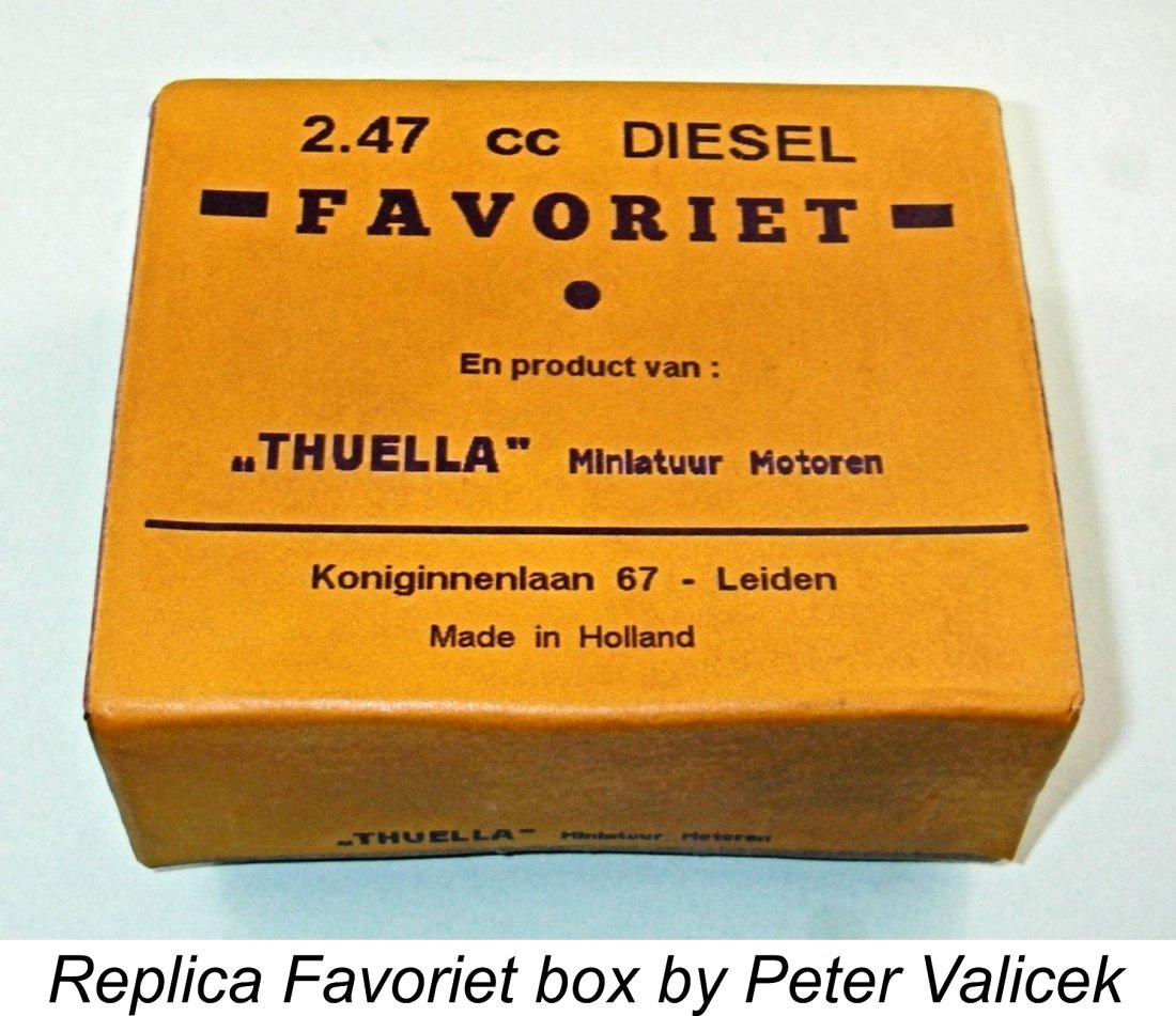
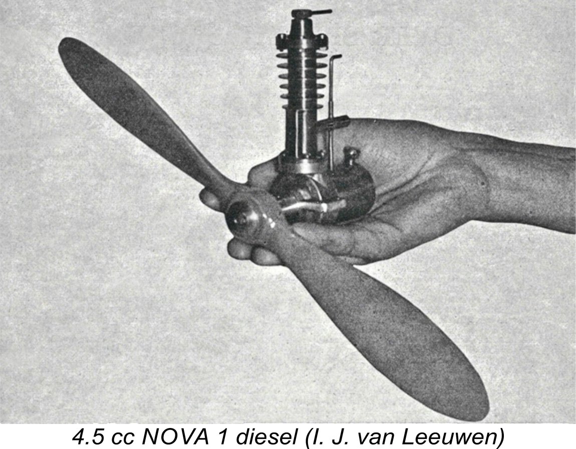 The first model diesel engine to appear in the Netherlands was the NOVA 1 of 4.5 cc displacement. The prototype was designed and constructed by I. J. van Leeuwen and was first tested in October 1943.
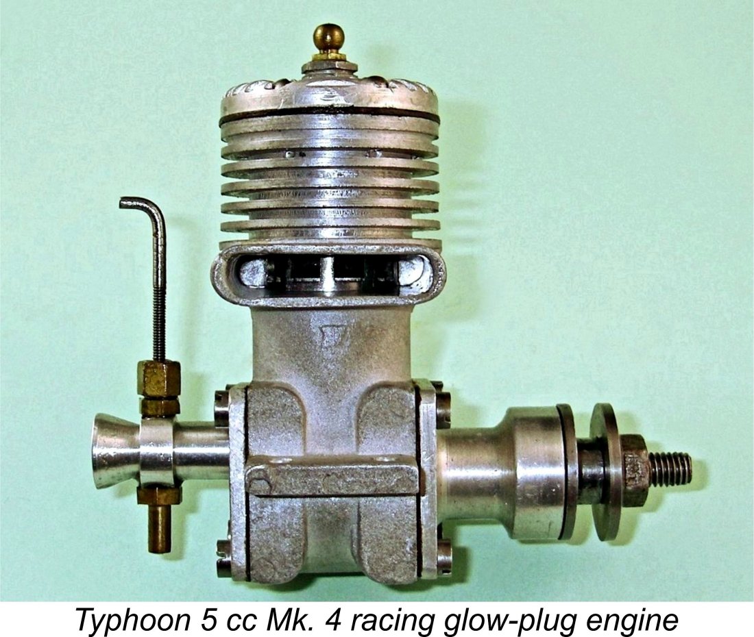
 The Thuella Favoriet is a compact and relatively lightweight 2.47 cc diesel of modest pretensions. Although at first sight it appears to be just another run-of-the-mill sports diesel, in reality it embodies a number of features which take it well out of the rut in design terms.
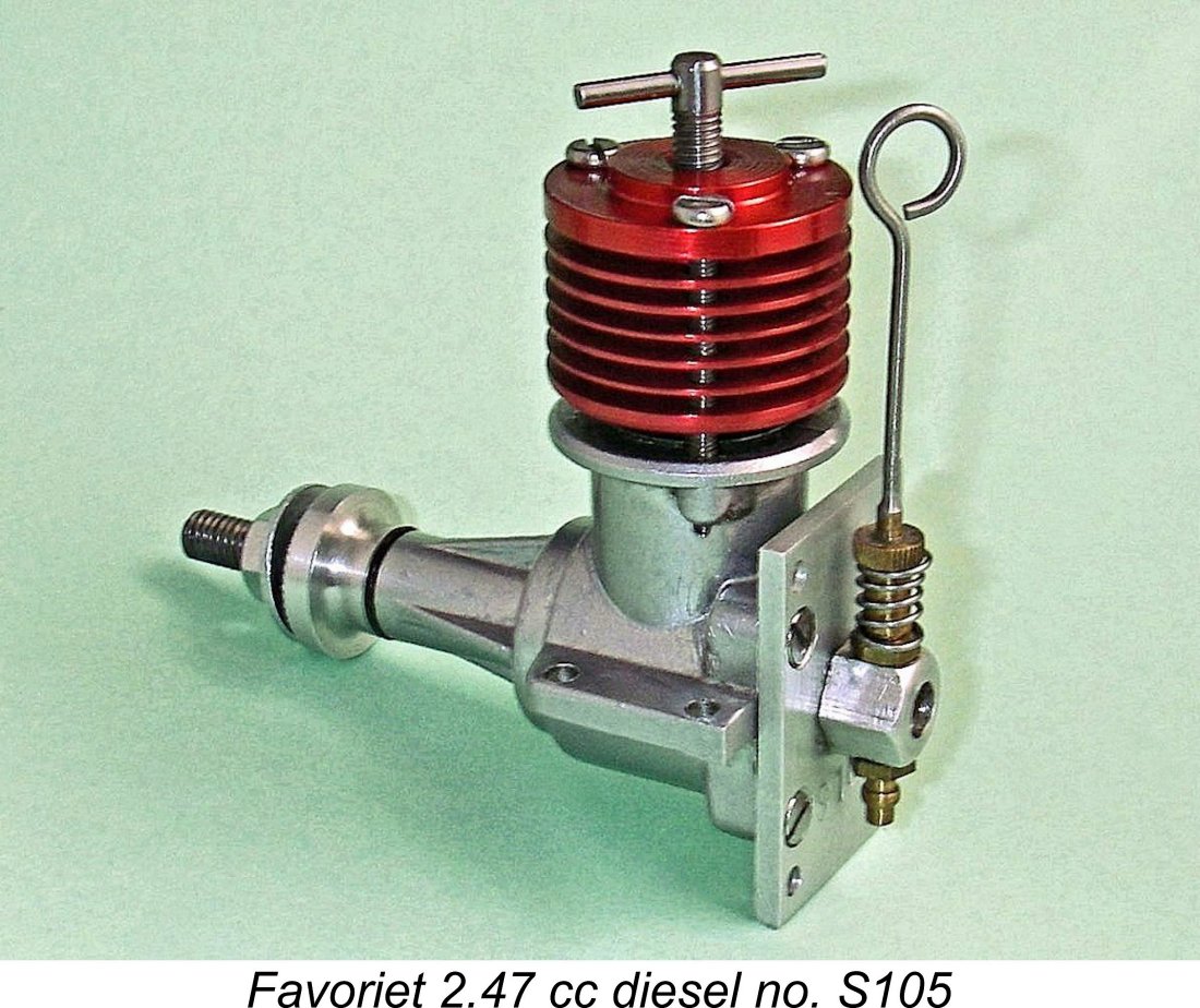
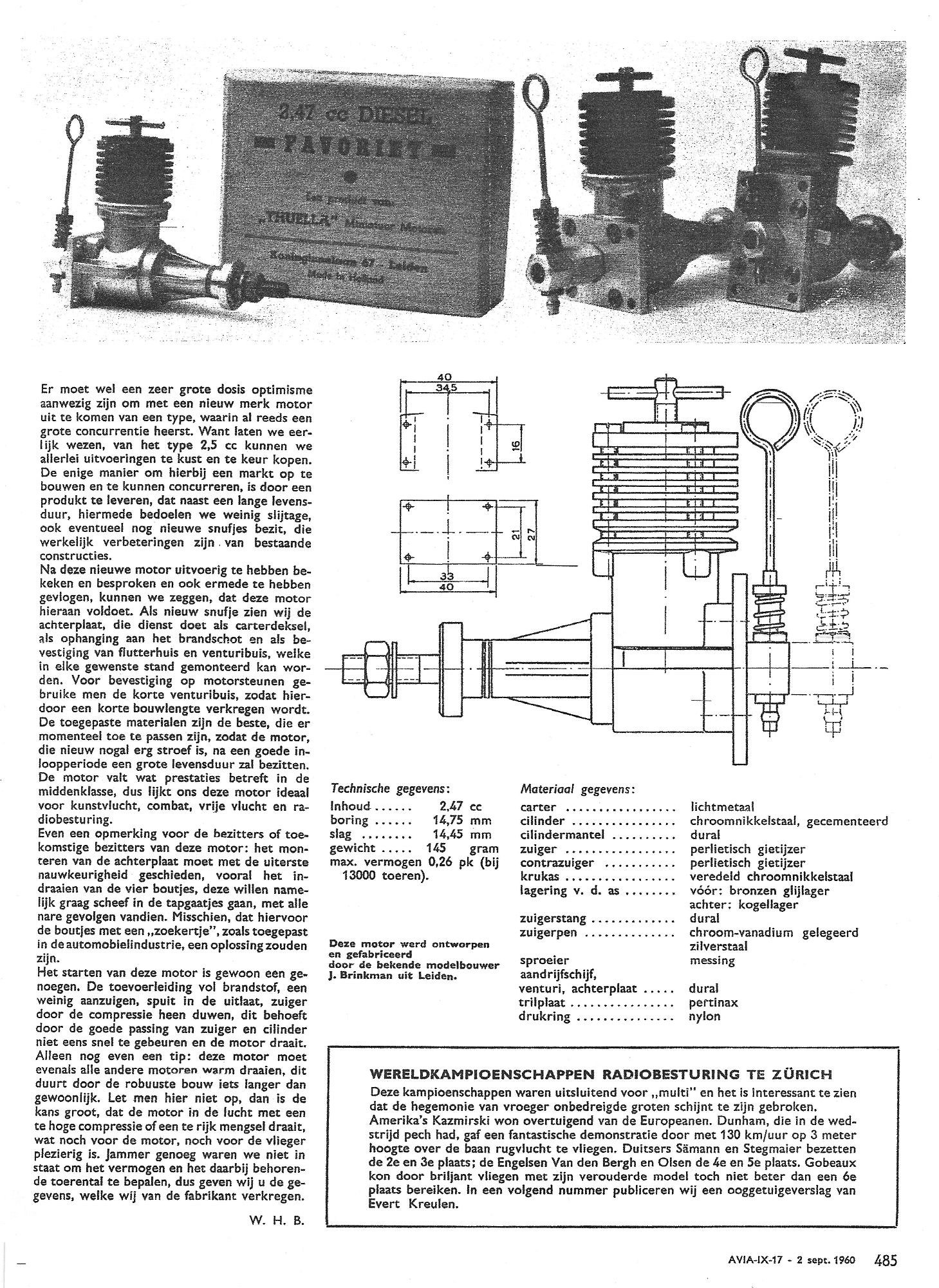 The introduction of the Favoriet in 1960 did not by any means go unnoticed among Dutch modelling enthusiasts. A review of the engine by one “W.H.B.” appeared in the September 1960 issue of the Dutch-language “AVIA” magazine. Rather than paraphrase this document, I will quote it in full in an edited English translation. The Dutch original is attached for reference.
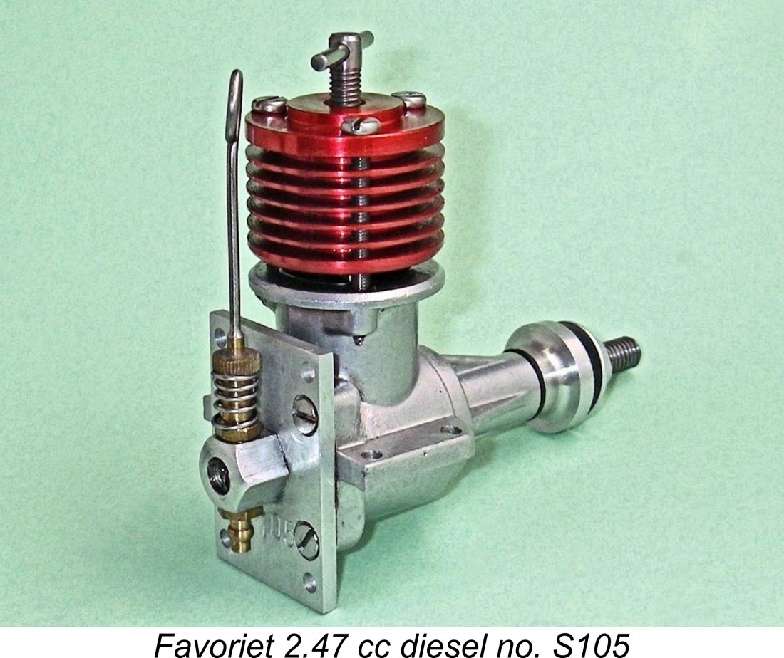
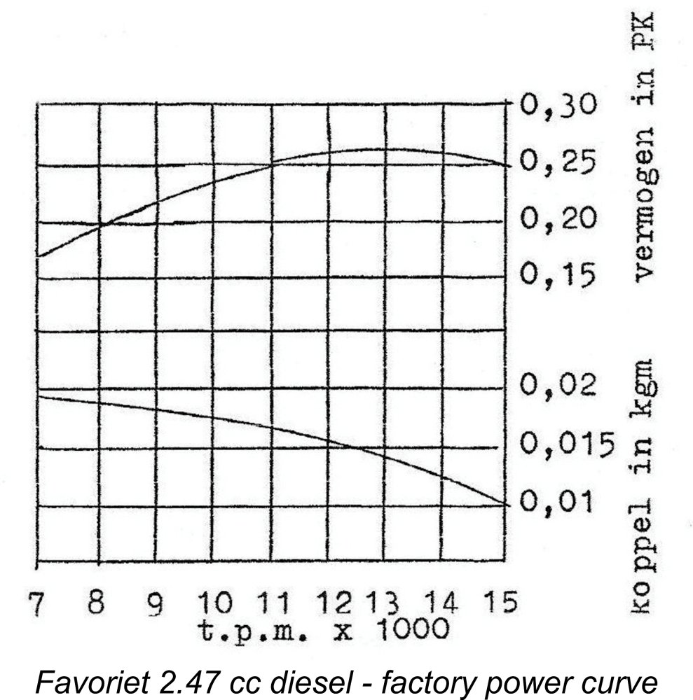 As previously reported, the "AVIA" review did not provide any performance data obtained at first hand. All that the magazine was able to do was cite the manufacturer’s performance claim, which was a peak output of 0.26 BHP @ 13,000 rpm. His power curve is attached here for reference. Let’s see what we can do to test this claim!
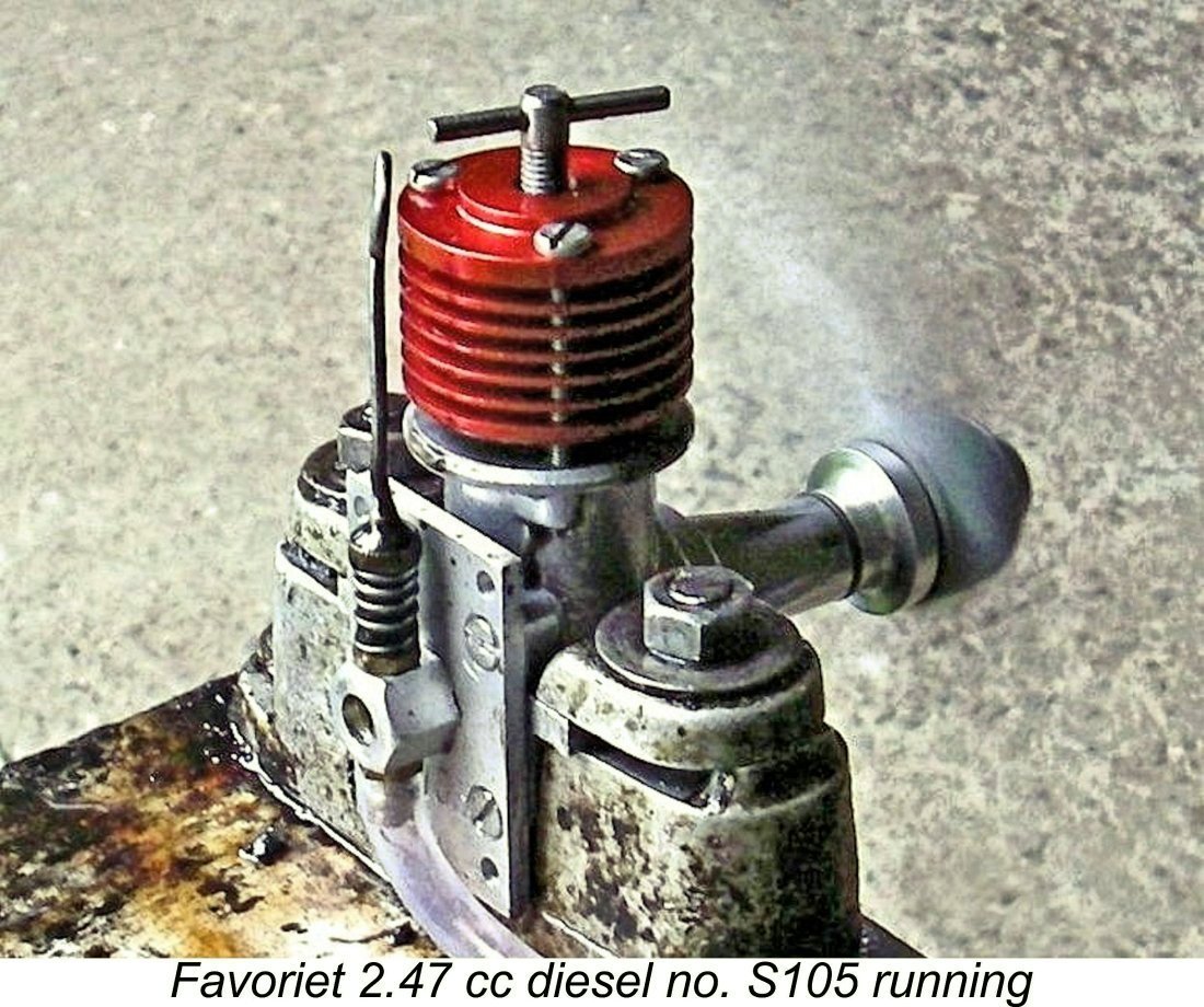 Once running, a further not-unexpected observation was the fact that the Favoriet displayed the usual flutter valve trait of a somewhat delayed response to the needle. It was necessary to make adjustments in small increments, waiting for a few seconds between increments to assess the effect. This behavior is perfectly normal for engines of this type, but it does add an element of complexity to the successful operation of such an engine, requiring some familiarization.
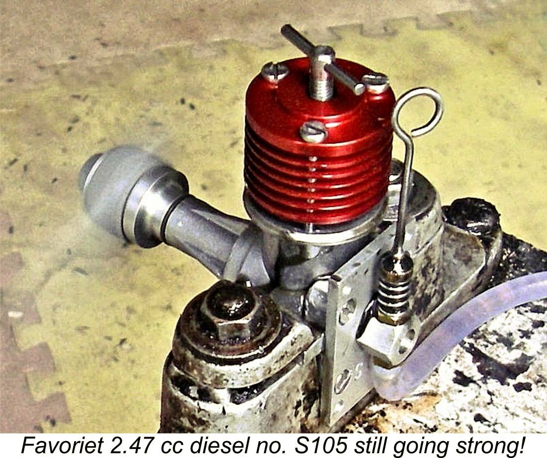
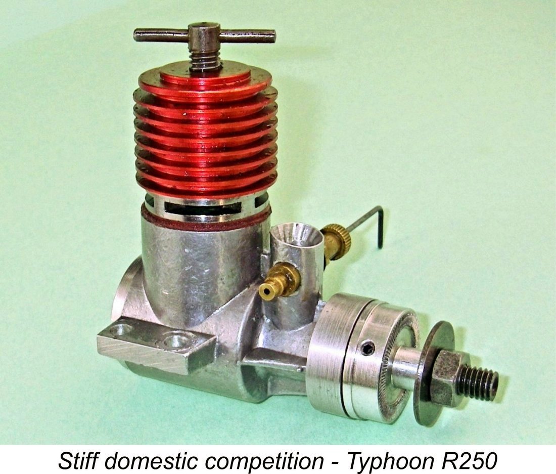 It’s clear from what has been presented above that the Favoriet was no threat in performance terms to the 2.5 cc contest diesel establishment as it existed in 1960. The competing Typhoon R250 from nearby Amsterdam stood head and shoulders above it in those terms.
 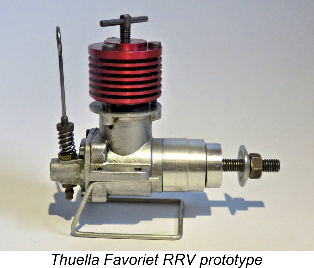 It appears that Hans Brinkman came to the same conclusion quite early on. There is direct evidence in the form of a single surviving example in the possession of Tom ten Brink that before production ceased entirely Brinkman was experimenting with a twin ball-race disc rear rotary valve (RRV) version of the engine. The fact that this was a prototype was clearly demonstrated by the engine's use of a standard single ball-race reed valve case which was converted to twin ball-race
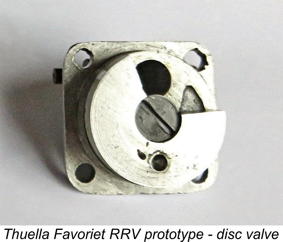
| |