
|
|
The Elfin Reed-Valve Ball-Race Models on Test
My primary purpose in writing the present article (which is effectively an addendum to my more comprehensive account) is to present tests of the two members of this series which were never the subject of full published test reports in the contemporary modelling media. When I conducted these tests, the results were so surprising that I deemed them to be well worth sharing with others. As received, both of the tested engines were suffering from a complaint which seems to have been depressingly common with these designs - namely, a broken reed valve. Based on my assessment as a former professional engineer, the design of the reeds was such that a metal fatigue failure was almost inevitable given even a moderate amount of running time. Since spare parts for these engines are of course not available, I had to improvise by making my own replacements. I can’t claim that my re-designed reed valves are necessarily superior in function to the originals, but I can confirm that both tested engines performed well beyond the levels which contemporary commentary had led me to expect. This allows me to state with confidence that the engines lost nothing in the way of performance when fitted with my replacement reeds - on the contrary, they both exceeded expectations. I can also confidently assert that from an engineering standpoint the revised reed design should be far less susceptible to metal fatigue failure than the originals. The design certainly works well enough to warrant sharing, which is another of my purposes in writing this article. Hopefully it may help others having similar problems with their examples. I’ll begin with the first model that I tackled - the original version of the Elfin 249 BR. For convenience in identification, this unit is generally referred to as the Elfin 249 BR Mk. I. I’ll adhere to that convention in what follows. The Elfin 249 BR Mk. I
Peter Chinn had a prototype of the 249 BR in his hands by March 1955, enabling him to describe the new model in detail in his "Accent on Power" column in the April 1955 issue of "Model Aircraft". He understood that the engine was expected to reach model shops within a few months of that date. Indeed, Aerol Engineering placed an advertisement in the April 1955 issues of both “Model Aircraft” and “Aeromodeller” which actually stated that the new 249 BR was “now on sale”. The cited selling price was £4 15s 0d (£4.75), quite a high price for a 2.5 cc diesel by then-current standards.
Like its 1.49 cc and 1.8 cc predecessors in the Elfin BR series, the new 249 BR Mk. I (as it is usually termed for convenience in identification) featured Oliver-style porting and reed valve induction along with a twin ball-race crankshaft. The rather unusual method of forming and securing the cooling jacket with a separate screw-on cap was also carried over. However, there were a number of structural changes in evidence.
Naturally, this arrangement necessitated the correct alignment of the transfer ports with these three bypass passages, negating the use of a screw-in cylinder assembly as featured in the 149 and 1.8 models. Instead, a leaf was taken out of the earlier "K" Model Engineering Co. design manual. The lower cylinder simply plugged into the upper crankcase, being retained there by a clamp ring reminiscent of the "dog collar" used on the K Vulture, Kestrel and Falcon designs.
Aerol Engineering's earlier predilection for long-stroke geometry re-surfaced in the new 249 model, which featured bore and stroke measurements of 14.41 mm and 15.24 mm respectively for a displacement of 2.486 cc. Despite this, the unique Elfin cylinder assembly kept the overall height of the engine down to perfectly "normal" proportions. The engine actually had a very attractive appearance, a fact which Peter Chinn was quick to point out.
The use of a long stroke naturally raised the bogey of potential vibration - another factor which had prompted criticism of the earlier 149 BR. The manufacturers made a serious effort to counter such effects by applying a very substantial counterbalance to the 249 BR’s crank disc. This was seemingly quite effective, as we shall see. In other respects, the new 249 BR was more or less a scaled-up version of its smaller siblings. The reed valve design was essentially identical, and the sub-piston induction used on the smaller designs was retained also, along with the Oliver porting.
As noted earlier, the design of the phosphor-bronze reed itself appears to have been inherently prone to fatigue failure in service. The reed is a rather intricate and delicate 0.002 in. thick stamping having a continuous circular outer annulus with an internally-protruding "flap" which serves as the actual working reed. The outer annulus is firmly tensioned against the inner face of the backplate recess by a relatively strong coil spring whose faces have been ground flat. A circlip keeps everything in place. The tension of the coil spring is sufficient to prevent it from participating in the induction process, leaving all of the opening and closing movement to be accomplished by flexure of the flap.
At this point I recalled the later Cox mylar reeds which were simple straight rectangular pieces of material with their ends rounded to fit the internal diameter of the backplate recess. Why wouldn’t a similar design work with the Elfin? So that’s the approach that I took. Using some 0.002 in. hardened and tempered shim steel, I cut a rectangle having the same length as the internal diameter of the backplate and the same width as the outside diameter of the sealing annulus on the backplate. I then rounded the ends by careful trimming and grinding to a very accurate fit against the internal wall of the backplate recess. To increase the reed’s flexibility, I also “waisted” it slightly on Feeling that the tension of the stock reed retaining coil spring was unnecessarily high, I made a new low-tension coil spring of far lighter material using standard piano wire. This allowed the ends of the reed some freedom to move laterally, which is essential if a reed of this kind is to work well. When the reed bends in the middle to open the valve, its ends have to draw closer together, much like the tips of a bent bow. They must therefore be left free to do so. This reed design is very easy to make, also eliminating any sharp corners at flexure points to act as stress concentrators. By sucking and blowing through the intake, I found that it seemed to work perfectly, opening with relatively little pressure and sealing tightly under suction. So far, so good! Next question - how well does it work in service? Time to find out …………. The Elfin 249 BR Mk. I on Test
In his somewhat truncated test report, Chinn noted that the earlier 149 and 1.8 BR models were "exceptional performers" and that the arrival of the companion 249 BR model had therefore been awaited with some eagerness by contest modellers. He went on to state that the performance of the prototype unit which he had examined in early 1955 had fallen "somewhat below that expected", and he surmised that the considerable subsequent delay in the appearance of the engine on the market had resulted from the manufacturer's efforts to correct this deficiency. With respect to the engine’s availability, Chinn commented in his January 1956 report that “the position regarding the supply of B.R. 2.49’s is not at all clear and few of these engines have yet appeared, it seems”. This leaves one wondering why the engine was advertised almost continuously from its introductory advertisement of April 1955 all the way up to January 1957, after which all Elfin advertising ceased.
However, it seems safe to surmise that since the original 1949 Elfin 249 plain bearing model had been found on test by Chinn to develop some 0.24 BHP @ 12,000 rpm, the 249 BR Mk. I must have failed to reach the 0.200 BHP plateau in Chinn’s hands. At a time when the prevailing specific output standard for "competition" model diesels was 100 BHP per litre or better, this was a far less than stellar performance for an engine having the advanced specification and higher-than-average selling price of the new Elfin. Indeed, it was very little better than the measured performance of the companion 1.8 BR, which developed 0.186 BHP @ 13,000 rpm on test. The Mk. I version of the Elfin 249 BR was never tested again - perhaps understandably, Ron Warring of “Aeromodeller” chose to pass on this one. Time for me to step up to the plate and give my own example a chance to show what it can do, re-designed reed and all! For this test I use a fuel consisting of 35% ether, 40% kerosene and 25% castor oil, to which I added 2% ignition improver. The engine was well used as received, hence requiring no break-in time. I therefore fitted an APC 9x6 prop and got straight down to it.
The engine also liked a small port prime for cold starting. The technique eventually adopted was to choke to fill the fuel line, inject a shot of fuel into the intake, administer a small port prime and start flicking. With this approach, starting was more or less immediate throughout the test - a few flicks invariably sufficed. I did find that the engine liked the needle to be opened about a quarter turn from the running setting for a dependable fuel pickup from a cold start. Hot re-starts were immediate at running settings. Starting remained excellent throughout the test. Vibration levels were well within acceptable limits - the counterbalance on the crankdisc was clearly very effective in that regard, especially considering the fact that this is a long-stroke engine. It turned out that the contra piston fit was fitted very much on the tight side. However, it never completely seized in the bore, although it occasionally displayed some temporary reluctance to follow a compression reduction. The contra piston in this model appears to be cast iron - a far better choice than the steel used in the two smaller models, since a cast iron component rarely freezes in the bore. My problems were purely the result of a very tight fit.
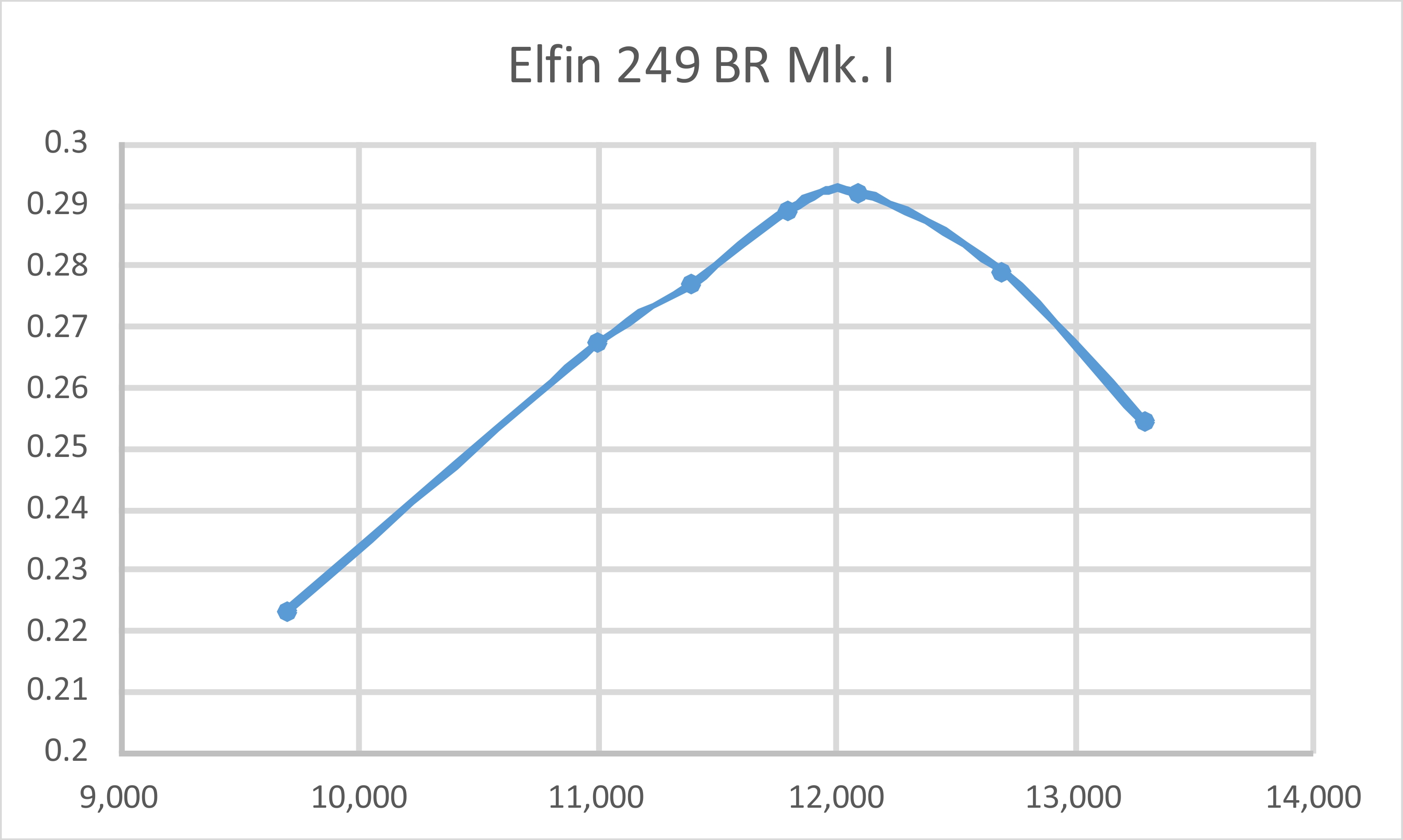
The reason for this behaviour is quite simple - with a reed valve, induction timing is variable, being controlled by the pressure variations in the crankcase during operation. The magnitude and timing of these variations will be significantly affected by engine speed. Unless you're very close to the optimum setting, a change in the needle setting almost invariably changes the engine speed and hence the induction timing. The engine requires a few seconds to stabilize at the new timing figures. I had actually run a few test props on this engine some years ago when I first acquired it and made my replacement reed valve. My notes show that it managed 9,600 rpm on a Taipan 9x6, 11,300 rpm on a Taipan 8x6 and 13,400 rpm on a Taipan 8x4. Since these figures suggested a somewhat more respectable performance than that evidently measured by Peter Chinn, I was naturally keen to see how it did using my calibrated set of APC props. Quite well, as it turned out! The following figures tell the story.
The two WB props are cut-down APC items created and calibrated to fill some power absorption gaps in my test set. As can be seen, the Elfin 249 BR Mk. I fell a little short of delivering a top-level performance by then-prevailing 2.5 cc competition ball-race diesel standards, but it did make a relatively respectable showing, doing far better than Chinn’s rather dismal assessment would lead us to believe. Up to around 12,000 rpm it actually stayed more or less level with the benchmark Oliver Tiger Mk. III which was the subject of Peter Chinn's test of December 1954. However, once the peak was passed, the output of the Elfin dropped off sharply with increasing speed, presumably because at that point the reed valve began to experience increasing difficulty in meeting the engine's fuel mixture requirements. We might expect a fairly sharply-defined peak with a resonant induction system, which would inevitably have a preferred speed range. The above data are completely consistent with such an expectation. Even so, the data reflect a peak output of around 0.292 BHP @ 12,100 rpm, thus falling a little short of the figures of 0.305 BHP @ 14,000 rpm reported by Peter Chinn for the Ollie Mk. III in standard trim. So …………not quite a top-class “racing diesel” performance, but a perfectly respectable result which suggests the development of above-average torque at speeds below 12,000 rpm or thereabouts. The engine’s long-stroke geometry doubtless helps here. It would certainly do a creditable job of powering the average non-contest model of its era. That having been said, it can’t be denied that even this level of performance makes the Elfin 249 BR Mk. I a bit of a second-rater in the all-out competition diesel sweepstakes. Moreover, although it would be a perfectly acceptable powerplant for non-contest flying purposes, its relatively high price wasn’t really justified in that context either. In summary, it was a refreshingly original design which handled superbly and ran well but failed to quite make the grade as a contest engine and was overpriced for other purposes. Viewed in that light, its failure to attract any real market interest is completely understandable. Now, before we move on to the next test unit, it seems appropriate for completeness to say a few words about the following variant of the Elfin 249 BR. The Elfin 249 BR Mk. II
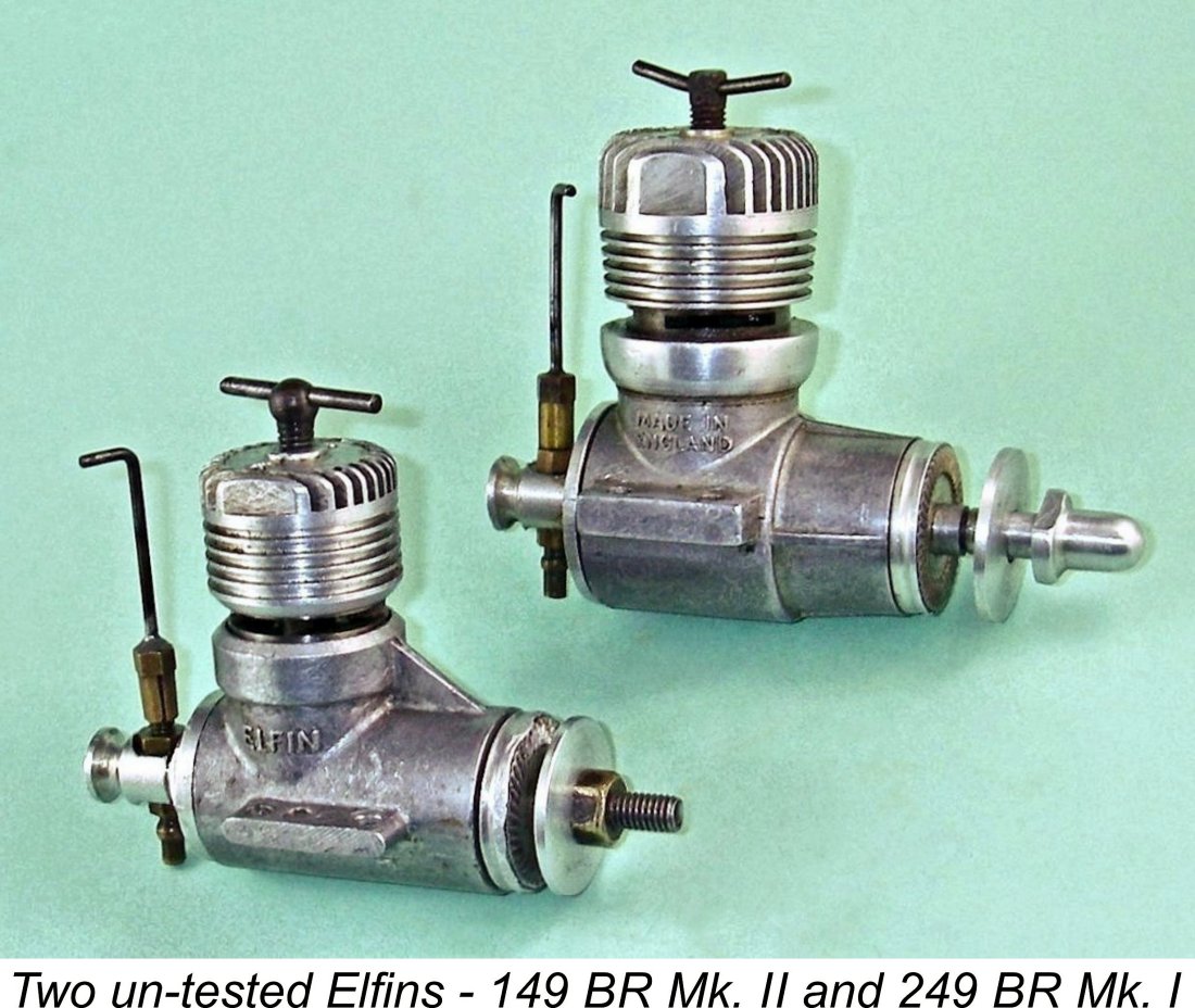
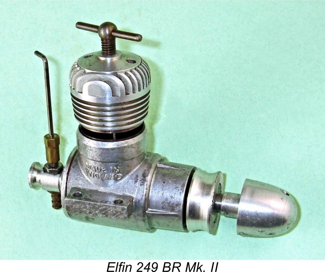
The revised model was basically similar to its 249 predecessor apart from its cylinder porting. The former drop-in cylinder with "dog collar" clamp ring was dropped in favor of a reversion to the far simpler screw-in cylinder used on the smaller BR models. Naturally, this meant that the radial alignment of the cylinder when fully tightened could no longer be guaranteed, but the revised bypass arrangements using internally-machined transfer flutes in place of the former Oliver-type porting rendered this unnecessary in any case. Presumably in an effort to maximize transfer efficiency, the new design featured four transfer and exhaust ports in place of the previous three. Geometric considerations made it impossible for the revised transfer ports to overlap the exhaust ports as in the earlier model, and the far shorter transfer period dictated by this no doubt acted to negate the effect of the additional bypass passage to a considerable degree. This version of the 249 BR was tested by Peter Chinn, who found that it showed a marked improvement in performance over the original Mk. I version despite the reduced transfer period. However, while the measured figures of 0.23 BHP @ 13,300 rpm may have been an improvement, they still fell well short of representing a true contest diesel performance. Ron Warring of “Aeromodeller” fared even more poorly in his November 1956 test, measuring only 0.202 BHP @ 13,200 rpm. It was probably this test that sealed the fate of the Elfin range. Despite these somewhat less than impressive figures, the changes noted above with respect to the 249 BR model were also applied more or less concurrently to the 149 BR model. Just how well this worked for the smaller model forms the central subject of the next portion of this article. The Elfin 149 BR Mk. II Given the significance of the changes made to produce this version of the Elfin 149 BR, it must be seen as a quite distinct variant of the engine. Accordingly, it seems appropriate to refer to the original Oliver-ported version as the Elfin 149 BR Mk. I, while the second variant to be discussed next is appropriately termed the Elfin 149 BR Mk. II. I will adhere to this protocol in what follows.
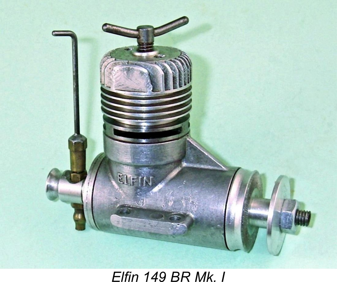
The configuration of the cooling jacket was also amended to better suit the new cylinder. The resulting engine was noticably more compact than its Mk. I predecessor. These changes undoubtedly justify the recognition of this as a distinct model - as can be seen in the accompanying image, the two variants are immediately distinguishable. The revised cylinder was to all intents and purposes identical to that which had been used all along in the original Elfin 149 PB model which had first appeared in 1950 - in fact, it may have been the same cylinder with the external threading of the upper cylinder amended slightly. The porting was also identically configured to that used in the revised 249 BR Mk. II unit of May 1956. Given the fact that the performance of the original 149 BR Mk. I had never been an issue, there seems little doubt that this change was made purely for cost-cutting reasons, quite possibly by creating a greater commonality of parts between the plain bearing and ball-race 1.49 cc models. Interestingly enough, the 149 PB and BR models were the only short-stroke engines ever produced by Aerol Engineering.
As noted above, the revised porting had resulted in a measurable improvement to the larger engine if Chinn is to be believed. It is therefore rather surprising to find that the same change when applied to the smaller model reportedly resulted in performance levels which actually fell somewhat short of those realized by the original Oliver-ported 149 BR Mk. I design of late 1954. To compound matters, it seems that the design changes to the 149 BR were not widely publicized, As a result, many modellers remained unaware of the changes and their evident effect upon performance. My good friend Irvin Ella recalled buying a 149 BR many years ago when in his teens and being extremely disappointed to find that it featured the revised porting just described and was noticeably down on power compared with the Mk. I versions owned by his friends. No doubt his reaction was typical and may in part explain why the Elfin range only survived for nine months or so after this change - there's nothing like unfulfilled expectations to dampen enthusiasm! So just how bad was this revised model? No time like the present to find out! The Elfin 149 BR Mk. II on Test We begin this portion of the article on a familiar theme! When the test example of the second variant of the Elfin 149 BR arrived, it followed the earlier lead of its big brother by having a broken reed!
I also elected to dispense with the coil spring altogether. I’ve already explained that the outer ends of a double-ended reed of this type have to be free to move inwards to accommodate the bow shape that the reed necessarily takes on when opened. The question became - what if anything did the coil spring contribute to this arrangement? The answer that I came up with following careful consideration was - nothing! So the coil spring went into the Elfin parts drawer, and I made a carefully dimensioned spacer ring out of aluminium alloy. I turned this externally to a close drop-in fit in the backplate recess and trimmed its length to provide a clearance of some 0.002 in for the reed when at rest, with the retaining circlip fitted - a total gap of 0.004 in., of which 0.002 in. is taken up by the reed. This left the ends of the reed completely laterally unrestrained in any way. The old suck-blow test through the intake showed that this reed valve worked perfectly both in passing air freely and in sealing very tightly. So how well did this modified reed work? To find out, I headed once more to my trusty old oil-soaked test bench. I used the same fuel that had worked well in the 249 BR, namely a blend of 35% ether, 40% kerosene and 25% castor oil, to which I added 2% ignition improver. Since this example appeared to be well used, I was able to get straight down to the testing with no need for an extended break-in.
The technique was identical to that used on the 249 BR Mk. I. That is, choke to fill the fuel line, inject a shot of fuel into the intake, administer a small port prime and flick. With this approach, starting was more or less immediate throughout the test. Once again, I found that the engine liked the needle to be opened about a quarter turn from the running setting for a cold start. Hot re-starts were instantaneous at running settings. A challenge which presented itself immediately was the fact that the contra piston fit was once again very much on the tight side. This problem was greatly exacerbated in this instance by the fact that the contra piston in the 149 BR is made of steel. Long experience with a number of different engines of various makes confirms that unless it is perfectly fitted initially, a steel contra piston in a steel bore will tend to lock solid shortly after the engine starts. Peter Chinn reported having this problem with one of the two samples of the original 149 BR Mk. I tested for his "Model Aircraft" review of that model. The compression setting was fully adjustable when the engine was cold, albeit a bit on the stiff side, but soon tightened up as the cylinder became hot, eventually seizing solid and thus preventing any further adjustment in either direction. A cast iron contra piston would undoubtedly be greatly preferable.
It quickly became apparent that my replacement reed valve worked as well on this unit as it had for the 249 model. There was no trace of blow-back at any speed. Running was extremely smooth, with very good suction in evidence. I found the needle setting to be a bit on the critical side, but that was mostly a reflection of a relatively coarse taper on the needle itself. The engine once again exhibited the typical reed valve characteristic of having a somewhat delayed reaction to changes in the mixture setting. I explained the reason for this behavior in a previous section of this article. Now we get right down to it! Having familiarized myself with the engine’s somewhat individualistic behaviour, I was able to extract very smooth consistent runs from it on all props tested. Running was dead smooth, with no misfiring and no tendency to sag. There was some vibration, but it didn’t appear excessive - that counterbalance on the crankdisc appeared to have had a positive effect. I also had little trouble with the engine starting in reverse - it only happened once on the 7x4 prop when I slightly overdid the port prime. Recalling the negative comments reported earlier regarding this model, I was frankly amazed at the quite unexpected level of performance indicated. Without flattering the engine in any way, the following data were obtained.
I can’t help these numbers - they’re what I actually saw, and I’m happy to duplicate them for any doubter who stops by! I even went back and re-checked a few of them at random just to confirm the figures. This particular example of the engine appears to develop around 0.187 BHP @ 13,300 rpm - a massive result by 1956 standards. Interestingly enough, this is right around the same peaking speed reported by both Peter Chinn and Ron Warring in their respective tests of the various Elfin BR models, but the actual power output is considerably greater, implying superior torque development. I have no idea of the extent (if any) to which my modified reed valve may have contributed to this performance. It’s clear that it works extremely well, but I have no legitimate basis for claiming it as the reason for this outstanding result. All that I can say for sure is that I found no support whatsoever for the negative views which have dogged this version of the engine ever since its introduction. Summary and Conclusion
The original Elfin 149 BR Mk. I was a very fine performer by the standards of its day but was cursed with a tendency towards excessive vibration, also being saddled early on with the unfair criticism that it was too heavy. As I’ve shown in my separate article on the overall series, the latter characterization was quite unwarranted, only arising because the Elfin was Britain’s first series-production 1.5 cc twin ball-race diesel (the Oliver Tiger Cub Mk. I was a special-order item) and people hadn’t yet grasped the seemingly obvious notion that the addition of ball-races would inevitably result in more weight. As the first British series-produced 1.5 cc ball-race diesel, the Elfin was the guinea pig, hence drawing the initial criticism and acquiring an undeserved reputation which has dogged it from that day to this. As matters were to evolve, it was actually one of the lighter twin ball-race 1.5 cc diesels to appear.
The Elfin 249 BR never really stood a chance in the British marketplace. Peter Chinn’s “censored” January 1956 report on the Mk. I version did nothing to inspire confidence, while both his subsequent test of the Mk. II version and that conducted separately by Ron Warring reported rather lacklustre performance levels by then-current competition diesel standards. Neither report would have attracted any buyer attention to the engine, especially considering its price. My own Mk. I example of the Elfin 249 BR performed at a significantly higher level than any of the three examples cumulatively tested by Chinn and Warring. Again, the extent to which my re-designed reed valve may have contributed is unknown. Regardless, the Elfin 249 BR may have had somewhat more potential than its reputation would suggest. However, it was still out of the contest hunt, albeit by a lesser margin than widely believed. So there we have to leave it! Whatever their failings, these units are fine-handling and smooth running model powerplants which do great credit to Frank Ellis’s design capabilities. It’s unfortunate that circumstances which have been related elsewhere prevented them from being developed to their full potential with the bugs all worked out. If you ever get the chance, give one a go - you’ll enjoy the encounter! And if the reed fails, you now know how to fix it! ____________________________ Article © Adrian C. Duncan, Coquitlam, British Columbia, Canada First published June 2022 |
||
 In a
In a 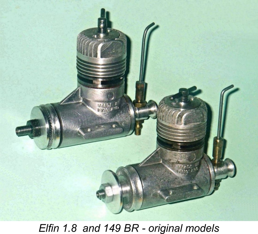 The Elfin twin ball-race reed valve series was launched in the latter part of 1954, with both 1.49 cc and 1.8 cc models being advertised in the October 1954 issues of both "Aeromodeller" and "Model Aircraft" magazines. However, later events showed that plans were already in hand to develop a similarly configured 2.5 cc design to supplement the range.
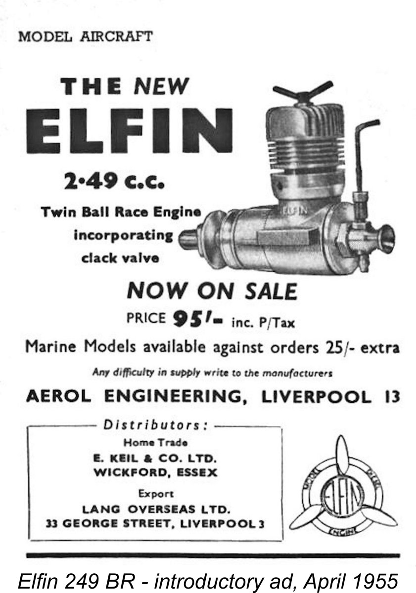 This advertising statement proved to be somewhat optimistic, since supplies of the new model were evidently very much delayed. It was not until considerably later in 1955 that the 249 BR finally appeared in small numbers in the model shops. Even then, availability appears to have been somewhat sporadic, accounting for the relative rarity of this short-lived model today. Despite this supply situation, the engine was advertised more or less continuously from April 1955 right through to the final Elfin advertisement of January 1957.
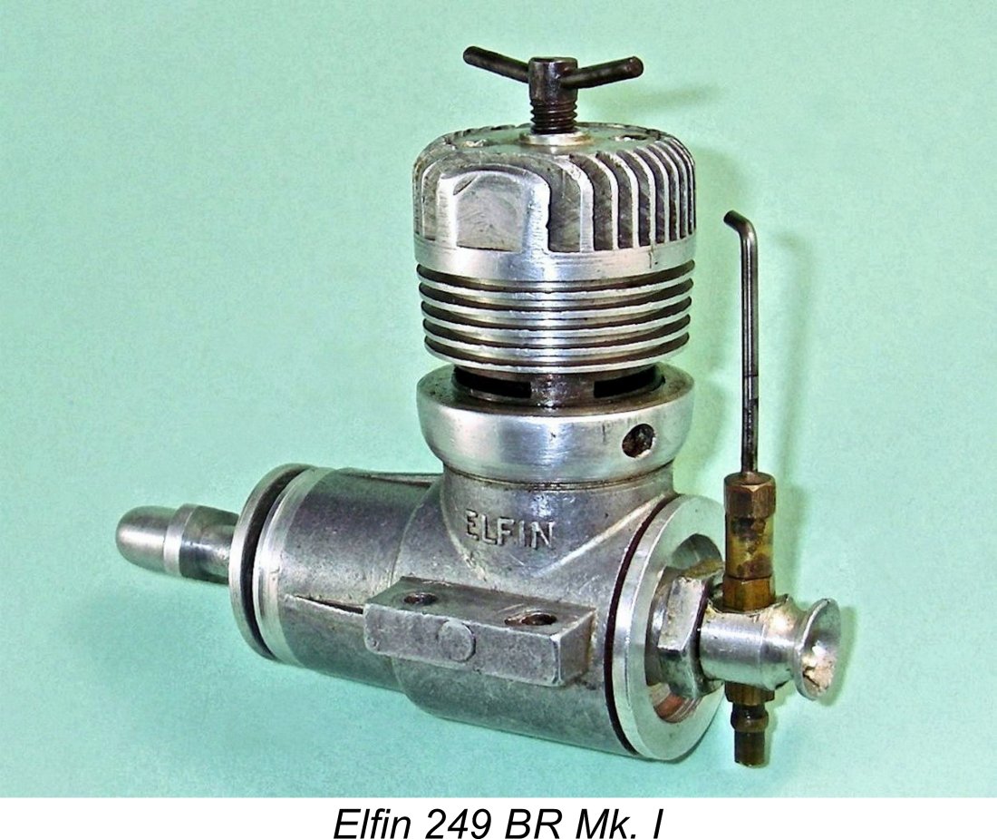
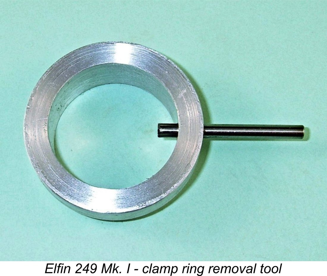 The internally-threaded clamp ring engaged with external threads machined onto the upper crankcase casting, It's essential to ensure that the cylinder is in the correct alignment with the crankcase when tightening the clamp ring down fully. It’s also essential in the interests of conservation to use the correct tool to either tighten the clamp ring or remove it for disassembly. No vice-grips, please - use an easily-made circular ring-spanner that engages with the radial hole in the clamp ring perimeter which is provided for the purpose. This hole is clearly visible in the above image of the engine.
 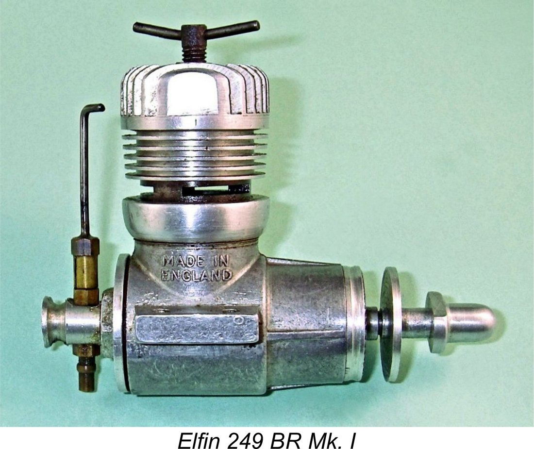 A further attractive feature was the engine's weight. The makers had presumably become a little sensitive to this issue as a result of the criticisms leveled earlier against the original 149 BR model in this regard. The new 249 BR model weighed in at a commendably light 136 gm (4.8 ounces) - only 23 gm heavier than the 149 BR model. This was a very low figure for a twin ball race 2.5 cc diesel - charges of excessive weight could certainly not be leveled against Elfin's new offering!
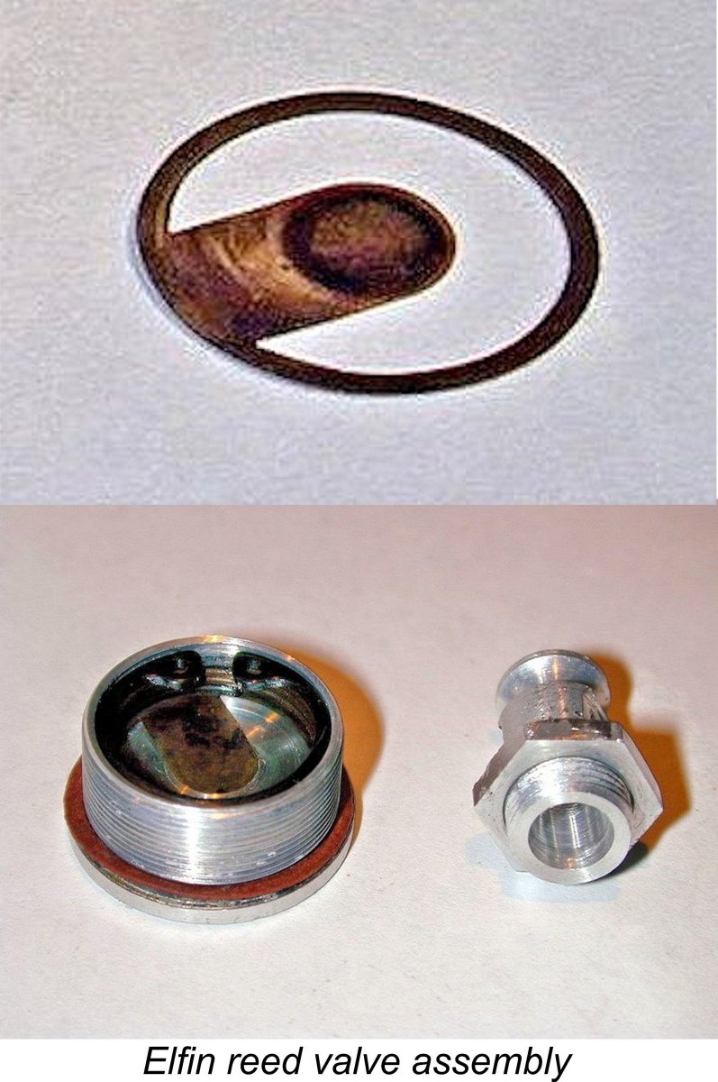 In my personal opinion, the use of sub-piston induction in a reed valve design is theoretically almost a necessity if maximum performance is to be achieved. Even the best reed valve is inherently more restrictive than a fully-open rotary valve, hence benefiting greatly from the assistance provided by sub-piston induction. Perhaps just as importantly, the feature has the great advantage of "releasing" the reed from crankcase pressure effects well before top dead centre is reached, thus giving the reed plenty of time to snap back into place on its sealing annulus before the sub-piston induction closes on the power stroke and crankcase pressurization begins. It's a little odd that other British makers of reed valve engines did not recognize and apply this principle. The German makers of the Taifun reed valve engines certainly did, to very good effect.
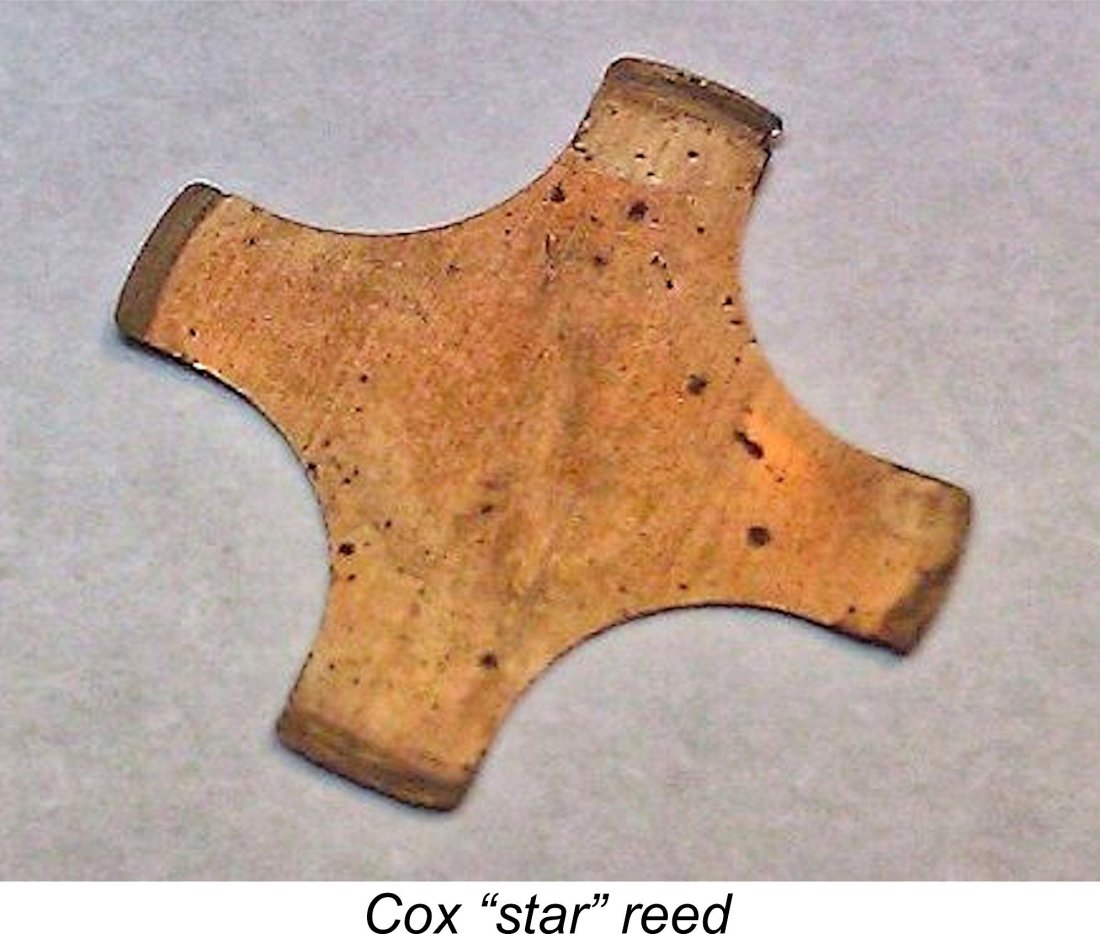 The amplitude of the flap’s movement is unrestrained in any way, while it features quite sharp 75 degree corners at the points where its edges intersect with the firmly-secured circular outer annulus. Since that is the location at which flexure stresses will be the greatest, the sharp corners will inevitably create cyclic stress concentrations at those points when the engine is running - a tailor-made recipe for metal fatigue failure. In my opinion, extended use of the engine is almost guaranteed to cause the reed to fail at the junction points. A Cox-style four-armed “star” reed with no sharp corners would be far better suited to the task.
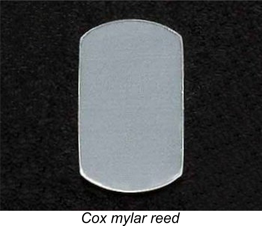 My example of the 249 BR Mk. I arrived some years ago with a reed broken in just this manner. I decided at once that I would not try to duplicate the original design - why replicate a component that has previously demonstrated a readily understandable tendency to fail?
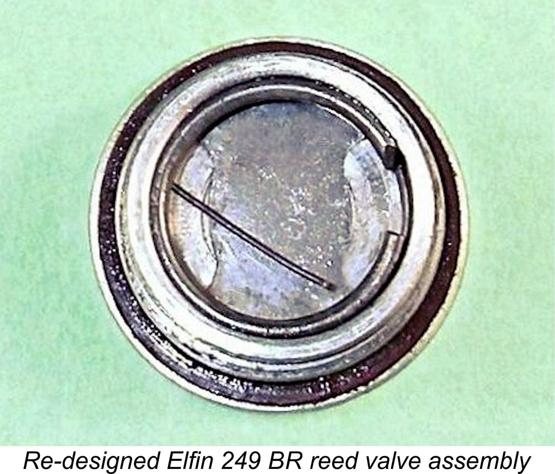 either side of the central sealing annulus, leaving the final shape as a “double hourglass”. Hopefully the attached image will clarify this description.
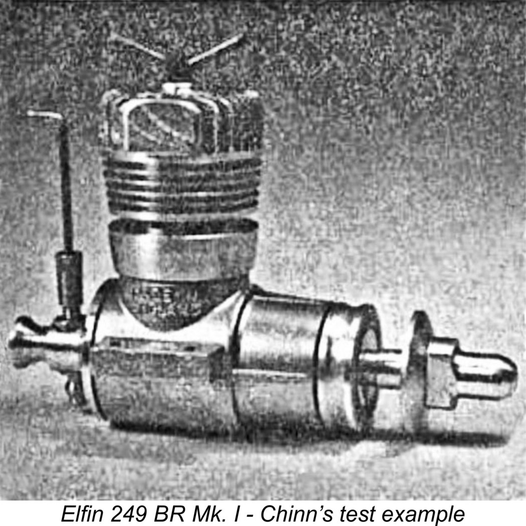 A
A 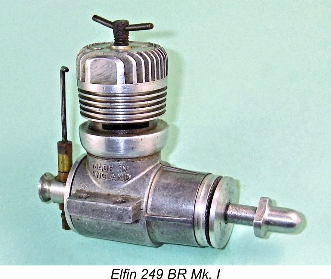 Despite the manufacturer’s presumed best efforts, the production version which was the subject of the January 1956 report was reportedly found to deliver some 15-20% less measurable performance than the original plain-bearing shaft-valve Elfin 249. In view of this, Chinn elected not to publish a full set of test figures for the 249 BR Mk. I, clearly fearing that to do so would embarrass the manufacturers, who were valued advertisers.
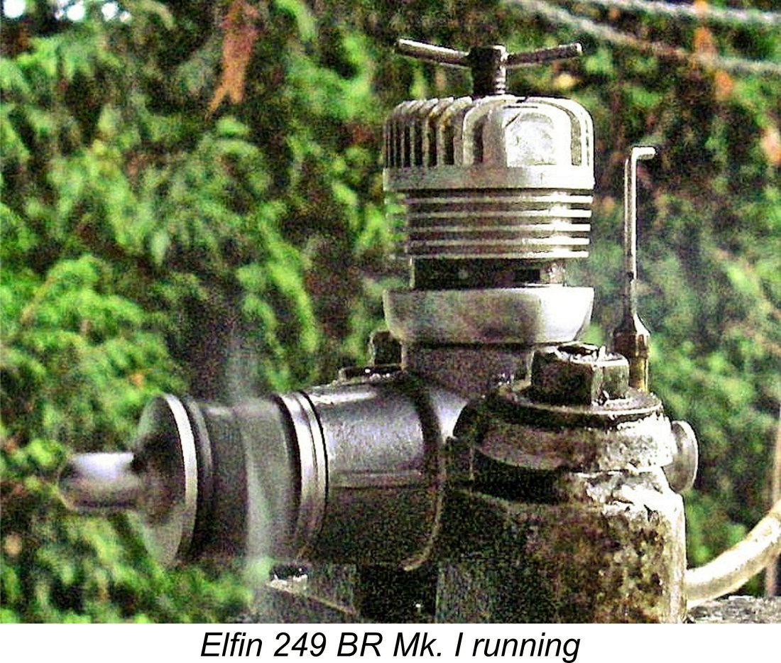 The Elfin proved to be a breeze to start, albeit with a few idiosyncrasies. The revised reed is perfectly flat and only lightly restrained at its outer edges. Consequently, it has no spring tension to keep it tightly closed in the absence of crankcase pressure. To get the reed valve sealing well at flick-over speeds, I found that a shot of raw fuel into the intake in lieu of finger choking was quite beneficial since it created a liquid seal between the reed and its seat. It was then only necessary to choke to fill the fuel line. I hasten to add that the engine would start OK without the intake prime - it merely started a little more readily using this approach.
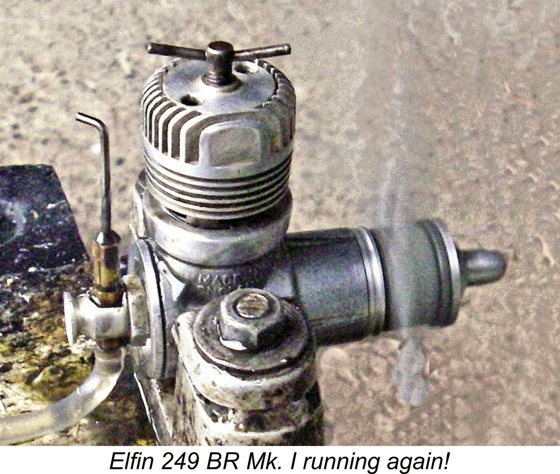
 It’s apparent that Aerol designer Frank Ellis quickly came to agree with the assessment summarized above. In May 1956 the Mk. I version of the Elfin 249 BR was replaced by a redesigned Mk. II variant. The revised 249 BR model (which is generally identified as the Elfin 249 BR Mk. II) appears to have been motivated as much by a desire to cut manufacturing costs as by a quest for increased performance.
 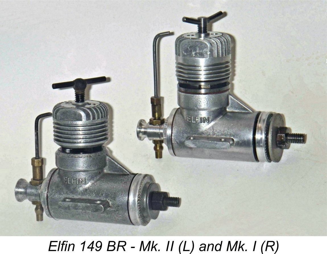 The most significant changes embodied in the revised model were once again focused primarily upon the cylinder porting. Nominal bore and stroke remained unaltered at 0.503 in. (12.78 mm) and 0.460 in. (11.68 mm) respectively for a nominal displacement of 1.49 cc (0.091 cuin.), but the engine was now provided with a revised cylinder featuring four transfer and exhaust ports, with the transfers being formed as internal flutes in the cylinder wall.
  The 149 BR Mk. II was provided with an improved compression screw of the type also used on the revised 249 BR Mk. II model. This was a definite functional improvement. Another welcome improvement was the addition of a small degree of counterbalance to the crankdisc, clearly in an effort to deal with the vibration issue which had brought down some criticism upon the Mk. I version with its plain unbalanced crankdisc.
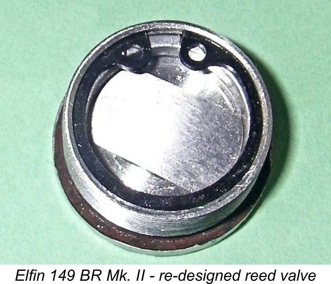 Of course, having previously sorted my 249 BR Mk. I very successfully using my revised reed design, I knew just how to proceed. I made a rectangular reed with rounded ends from 0.002 steel shim stock, just as before. However, this time I decided to dispense with the double hour-glass profile in favor of a parallel-sided reed, just as used by Cox.
 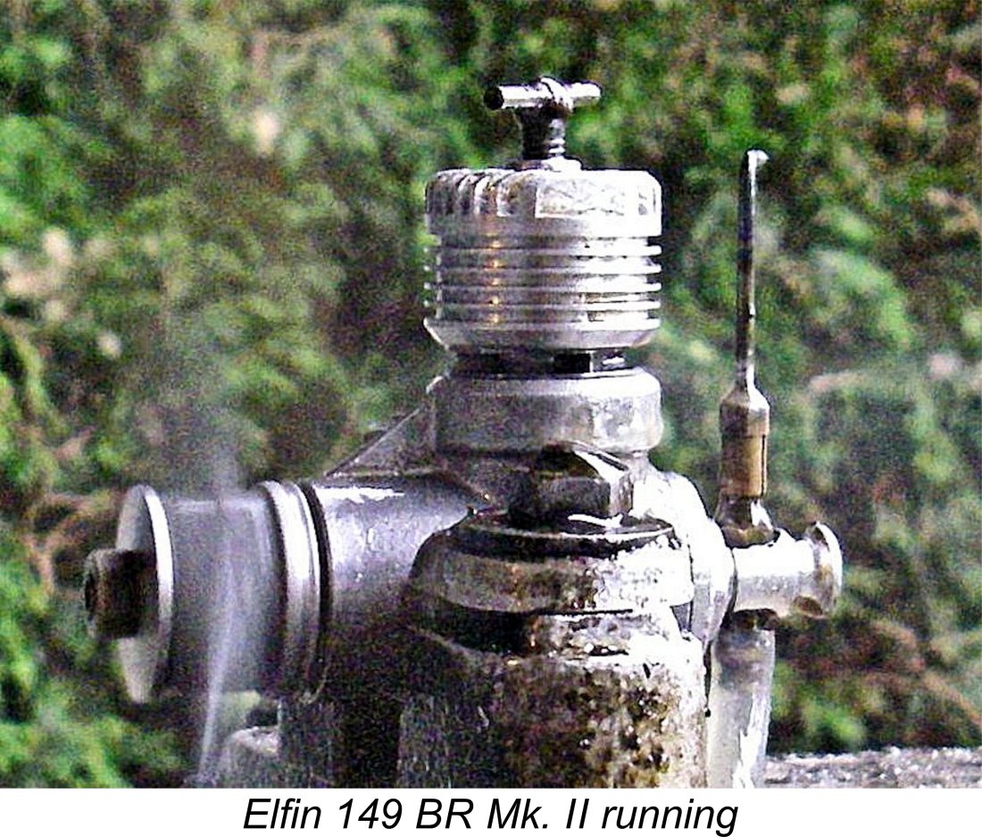 The engine proved to be a very prompt starter, behaving very much like its 249 BR Mk. I counterpart tested earlier. Once again, the revised reed is both perfectly flat and completely unrestrained, hence having no spring tension to keep it closed in the absence of crankcase pressure. As in the case of the larger model, I found that a shot of fuel into the intake in lieu of finger choking was most effective in helping the reed to seal at flicking speeds. The engine also liked a small port prime for cold starting.
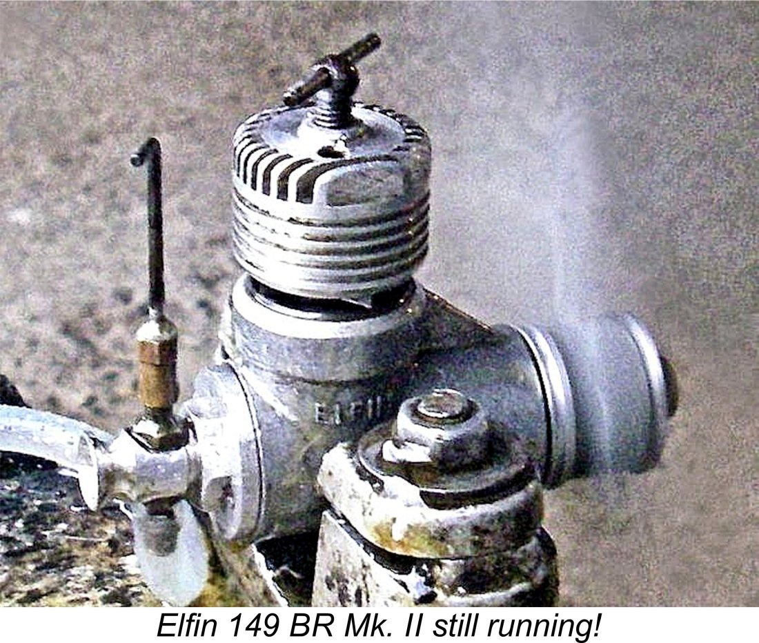 As matters stood, it was necessary to assess the engine’s performance on a given prop and estimate the best compression setting for the next prop to be tested given its speed expectations. After fitting the new prop, the engine would be started and the compression immediately set at the estimated position, where it would stay for the rest of the run. Not ideal, but I had no trouble getting smooth sag-free runs out of the engine on every prop tested. 60 years of experience was a great help here! If a prop change was not required between runs, as in a model, the engine would happily start on the running compression setting.
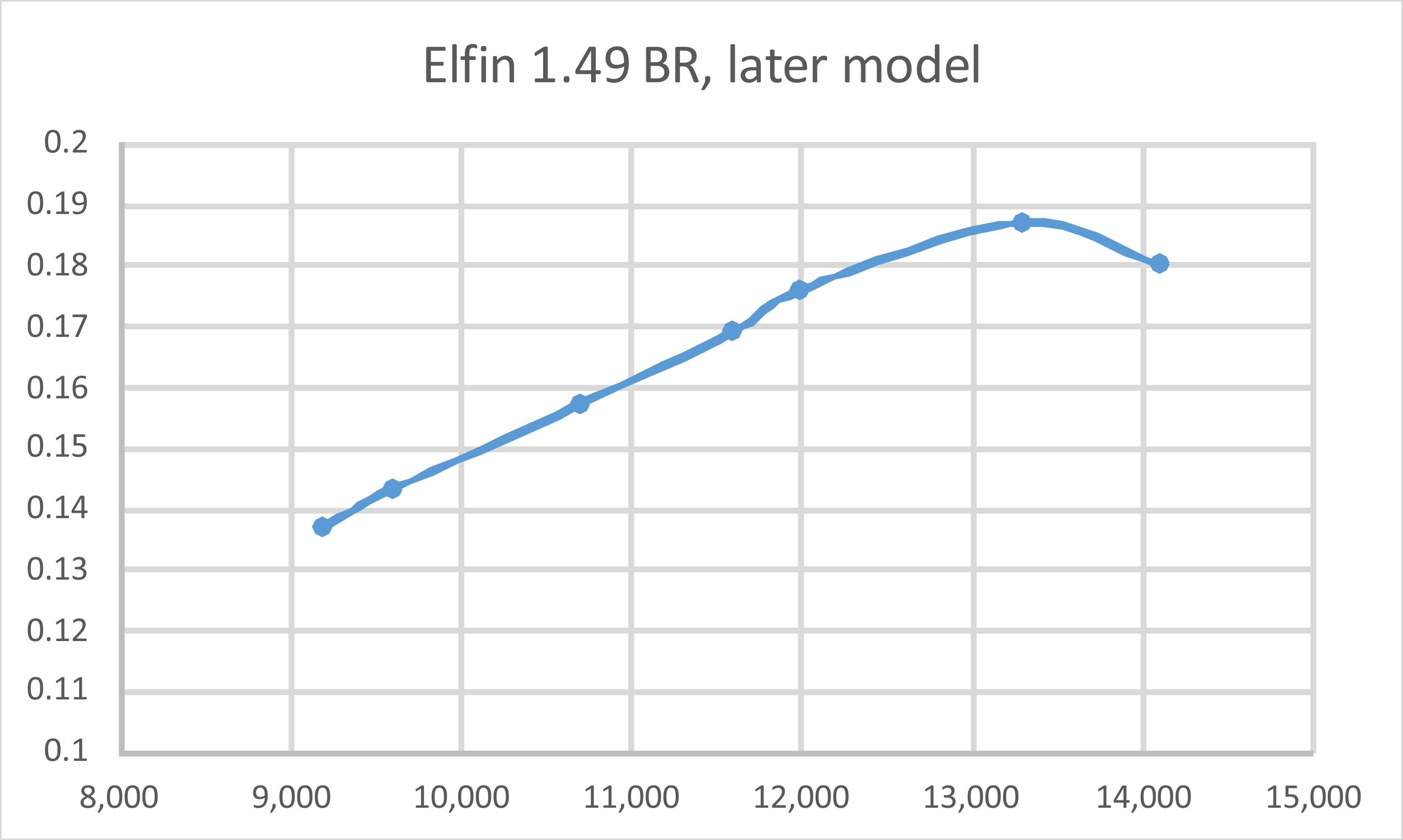
 The Elfin BR models may legitimately be summed up as highly innovative technical near-misses which were commercial failures. On the one hand, they demonstrated the potential of the application of reed valve induction to model diesel engines for all to see. On the other hand, they all seem to have had operational or design issues of one sort or another.
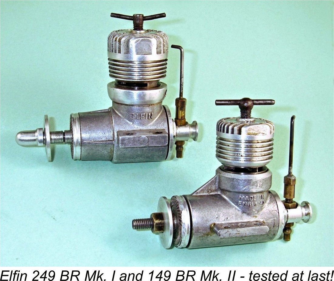 The replacement model, the Elfin 149 BR Mk. II, seems to have established a reputation as an under-performer in its day. I accept this, but can only say that my own test failed to provide any support for this view - in fact, my test example performed at a level which was right at the top of the British 1.5 cc contest diesel heap as of 1956, also vibrating quite a bit less than the Mk. I version. I’m unable to say how much of its performance is due to my re-designed reed valve - all I can say for certain is that my valve clearly works extremely well in this engine.
| |