
|
|
The Elfin Ball-Race Models
Beginning in late 1954, these refreshingly out-of-the-rut designs were apparently introduced by their manufacturers, Aerol Engineering Ltd., in a technologically impressive but commercially unsuccessful effort to keep pace with the ever-improving competing designs then appearing from other British and overseas producers. Their evident failure to meet with sufficient success in the contemporary marketplace to justify continued production certainly merits an attempt at an explanation. There are also a few "legends" associated with these designs that warrant an objective evaluation. An earlier version of this article appeared in February 2010 on the late Ron Chernich’s “Model Engine News” (MEN) website, where it may still be perused. The publication of this revised version on my own website has been prompted by the emergence of some additional insights and test data since the publication of the original text on MEN. Apart from that, the quality of the photographs used to illustrate the original article left much to be desired - I was still learning that art at the time! Moreover, the article was badly organized and poorly written in spots. I think I can do better now ……….. It's a very well-known fact that the ball-race Elfin models were produced in three displacements - 1.49 cc, 1.83 cc and 2.49 cc. What seems to be far less well-known is the fact that each of these three models was offered in at least two quite distinct variants. It's my intention here to make at least an initial stab at sorting this out for my fellow enthusiasts. That said, I don’t claim to have all of the facts at my fingertips, and if any reader is in a position to correct me or to add to our shared knowledge, I'd love to hear from you! Acknowledgements Before proceeding any further, there's a long list of friends to be thanked. First, I wish to acknowledge the very considerable assistance extended to me by my good English friend Kevin Richards. Although the bulk of the text is my own and I accept full responsibility for its contents, I must record the fact that Kevin has added considerably to my knowledge of the background to the Elfin range and has set me straight at a few places where I was going wrong. Thanks, mate! I must also record my debt to the late Bert Streigler for kindly sharing his personal recollections from his days as an Elfin importer to the USA and for checking the original text for errors and omissions. With good friends like this helping out, my task was made very much easier than it would otherwise have been. In addition, I've borrowed freely from the late Ron Chernich's earlier text on the Elfin 149 BR. This saved a lot of time, and I'd like to express my sincere appreciation for Ron’s unstinting help and encouragement during the writing of the original text.
Firstly, Jim Woodside was kind enough to share his personal knowledge of the Elfin range. Much of this was gleaned through direct contact with Aerol Engineering co-founder Frank Ellis, who was a fishing buddy of Jim's uncle (another Jim!) and helped him get started in aeromodelling. In particular, Jim was able to set me straight in a few areas where I had gone somewhat astray. Such first-hand insights are quite invaluable, and my very sincere thanks go to Jim. The most valuable resource contributed by Jim was a tape of an interview which he had conducted with Frank Ellis in around 1990 when Frank was around 85 years old but still as sharp as a tack. Frank's crystal-clear personal reminiscences and razor-sharp insights added a great deal to the story of the Elfin range, and we are all greatly indebted to Jim not only for preserving this priceless record but for generously making it available for research purposes. Subsequently, the late Ron Moulton located a more complete recording of the interviews with Jim, of which he was kind enough to send along a copy for my reference. The additional material provided further clarification of a number of matters, and Ron deserves my very sincere thanks for his invaluable assistance. We miss him ………. Finally, upon reading the text as originally published. my friends and colleagues Irvin Ella and Eric Offen were kind enough to send along some additional information which did much to clarify the later history of the range following the final change of ownership. All I can say once again is - thanks, mates! Background
However, Jim Woodside was able to confirm that the business of Aerol Engineering was actually conducted from an entirely separate edition of Henry Street located well to the east of the City Centre in Liverpool 13. This street still existed in 2009 in the form of a cul-de-sac off Edge Lane, but it was quite hard to find since it didn’t come up in a Google search for Henry Street, Liverpool despite appearing on a then-current Google map of the Liverpool 13 area. It has since disappeared, having been built over during the construction of the massive Liverpool At the time of which we are speaking in this article, the area was characterized by a mix of housing and industrial activity - for example, the Triang factory where Meccano erector sets were made (under the direction of then well-known aeromodeller Doug McHard, now deceased) was located nearby on Binns Road. The Aerol Engineering venture was the brainchild of the previously-mentioned Frank Ellis, who had worked during WW2 at the nearby Dunlop plant and had subsequently gone into the scrap metal business at Henry Street in partnership with a chap named Finn. The making of model engines was apparently a labor of love for Ellis, who had constructed a number of diesels in his spare time during the war. Moreover, there was a direct connection between his two business interests, since the partners' scrap-yard supplied the bulk of the raw materials for the new company's products. According to information supplied by Jim Woodside, the original "factory" in which Aerol engines were manufactured was simply a lean-to in a corner of the Henry Street scrap-yard! Later, a purpose-built brick factory was constructed at the same location, and this remained in use for the duration of Aerol's subsequent production activities. Start-up funding for the venture was provided by the Liverpool cotton brokerage firm of Davies, Benachi & Co, who also acted somewhat improbably as Aerol and Elfin overseas distributors for some years. This connection resulted from the fact that the senior partner, Colonel Thomas E. H. Davies, was a friend of Frank Ellis and a model engine enthusiast himself who admired Frank’s earlier efforts. The machine tooling used to manufacture the engines was well-used wartime equipment which had become surplus upon the cessation of hostilities and was therefore available at modest cost - many early post-war British model engine manufacturers took advantage of such opportunities. As a result of its wartime service, this equipment was "tired", i.e., totally knackered! Its enforced long-term use proved to be responsible for many of Aerol Engineering’s production problems, probably doing as much as any other factor to hasten the end of the marque, as we shall see. In his taped interview with Jim Woodside, Frank Ellis recalled that at one point in early 1952, arrangements were made with Davies, Benachi & Co to secure funding for new production equipment. Sadly, this plan fell through when the company’s main financial backer, Colonel Davies, unexpectedly died. Frank reckoned quite seriously that if Colonel Davies hadn't died when he did, the Elfin range would have lasted far longer. The castings for the engines were produced under contract at a foundry in Blackpool. When Jim Woodside checked in the early 2000’s, the foundry was still in existence, but there were no records or recollections of the Aerol contracts and no surviving patterns or dies. Jim believed that Mike Booth, a well-known control-line flier in the '40's and '50's then living in Blackpool, may have had a hand in arranging for the production of these castings.
Regardless of how it came about, the Gremlin was undoubtedly the design that got Aerol Engineering started in the model engine business. It was a simple plain bearing front rotary valve (FRV) engine featuring a gravity die-cast case, a radial tank mount, an updraft carburettor and a beehive-shaped cooling jacket having only a single exhaust port in a rather unusual location. The engine had a very neat and uncluttered appearance - in fact, the styling was unquestionably both elegant and "futuristic" by 1947 British model engine standards. Frank Ellis admitted that he was greatly influenced by the Arden engines from America in developing this and other early radial-mounted Aerol designs. Frank recalled the Gremlin as being "a terrific engine", He claimed that they ran one for 15 days straight (some 360 hours) on a big tank at 8,000 rpm, and when dismantled after the test it was found to be as good as it had been when first assembled. My own testing has confirmed that the Gremlin was indeed a very useful model powerplant which would have served its owners well. I found a peak output of over 0.13 BHP @ 9,000 rpm - an excellent performance for a 2 cc diesel in 1947.
My example of this engine is a fine runner, albeit displaying no real performance edge over the Gremlin. Its design seems to have been aimed as much as anything at dealing with a few assembly challenges. A full review and test of both the Gremlin and Hurricane may be found here. It appears that the Gremlin and the Hurricane were well received by the modelling public, although their relative rarity today confirms the logical expectation that total production figures during their very short commercial lifetimes were not high. Many examples apparently went for export, while those that remained in England seem to have been marketed for the most part in the Liverpool area. Nevertheless, Aerol Engineering was sufficiently encouraged by the response that they decided to forge ahead with an expanded and further updated range. To help market the new products, the partners now applied the rather catchy ELFIN trade-name to the engines. The derivation of this name has often been a subject of conjecture, but in reality it's absurdly simple once you know the names of both partners! ELlis + FINn = Elfin - pretty straightforward really!
The first Aerol product to receive the Elfin name was released in the latter half of 1948 as a replacement for the Hurricane. This was the famous gravity die-cast radial-mount FRV 1.8 model, which was a direct derivative of its predecessor but represented a clear step forward in design terms. The slightly smaller displacement of 1.84 cc (0.112 cu. in.) was achieved through a reduction in the stroke from the .609 in. (15.47 mm) of the Hurricane to 0.562 in. (14.27 mm), the result still being a long-stroke engine. The bore of the 1.8 was essentially unchanged from that of the Hurricane at 0.505 in. (12.83 mm)
The early years of the Elfin range were marked by rapid change. In 1950 the original radial mount Elfin designs were supplanted by completely revised PB models in the 1.5 cc and 2.5 cc categories, corresponding to the displacement limits for the S.M.A.E. Class I and Class II competition classes then in effect in Britain. These new offerings featured revised cylinders and pressure die-cast crankcases having provision for beam mounting, by then more or less the accepted standard in The beam mounted 2.49 failed to match the performance of its radial-mounted predecessor. This has led to much speculation regarding the reason(s) why the company switched from the original and very successful 1.8 and 2.49 cc models to the beam-mounted versions. When asked about this by Jim Woodside, Frank explained it very simply - demand was rising; they were under pressure to make more engines; and they could turn out the beam-mount models faster than they could The Elfin PB engines continued to be widely used by British competition modellers in the early 1950's, chalking up a most impressive contest record during that period which can't have hurt their sales figures. In early 1952, the neat little 0.54 cc Elfin 50 model was added to the range. However, production difficulties arising from the clapped-out state of the company's elderly machine tooling resulted in that model being dropped fairly quickly following the above-mentioned failure to secure new production equipment due to the death of Colonel Davies. Frank recalled that this step was taken very reluctantly, because he reckoned that the Elfin 50 would have been a very good seller. It was certainly a fine performer. I’ve documented its rather sad history elsewhere. I hope to present a more detailed history of the Elfin plain bearing engines in a future companion article, For now, the above summary will have to suffice. The Basis For Change
Furthermore, things were not standing still - other British manufacturers were soon challenging Elfin's position in the marketplace. E.D., FROG and Allbon all had highly-regarded 1.5 cc models on sale as of the early 1950's, while the 2.5 cc class was becoming increasingly competitive also, with E.D., Reeves and FROG all having updated designs on the market along with specialist makers such as Oliver. Clearly, Aerol Engineering came to feel that they had to do something drastic to re-establish their former position as trend-setting British manufacturers. Making updated versions of their own (and their competitors') essentially conventional designs evidently didn't fit the bill - they decided to demonstrate their capabilities by creating something really different. As we shall see, they certainly succeeded in achieving this goal! They did so by unveiling as drastically revised a range of models as has ever been sprung on the modelling public by a British manufacturer - the famous twin ball-race reed valve Elfin series which will form our main subject from here on in. 1954 - The First Elfin Ball-Race Models Appear
The 1.8 cc model seems a strange size, sitting between competition classes. Its presence in the range was almost certainly inspired by the immense popularity of the earlier plain bearing 1.8 cc radial mount updraft FRV model among free-flight competitors (then very numerous) due to its exceptional power to weight ratio. The 1.8 BR replacement was somewhat heavier at 118 gm as opposed to 93 gm, but it was significantly more powerful by way of compensation. Aerol Engineering must have been hoping to cash in on the fond recollections of the old 1.8 which doubtless persisted among British modellers. In addition, the fact that both of the new ball-race models shared the same crankcase casting and mounting configuration meant that the 1.8 represented a bolt-in replacement option that could be fitted into the same model if more power was required and the displacement was not a class conformity issue. The fact that the 1.8 BR weighed only 5 When designing slightly larger-displacement variants of a given engine based on a common crankcase, manufacturers generally take the expedient route of creating the additional displacement simply by increasing the bore of the engine. Unusually, both the Elfin 149 and 1.8 cc BR models used the same bore of 0.503 in. (12.78 mm), the additional displacement of the 1.8 being obtained by lengthening the stroke from 0.460 in. (11.68 mm) to 0.562 in. (14.27 mm) for a displacement of 1.83 cc (0.1117 cuin.). The bore and stroke dimensions of the 1.8 BR were actually identical to those which had been used in the original plain bearing 1.8 cc models.
A quick calculation shows that the conversion of the 149 BR to a 1.8 model by increasing the bore would have involved a bore increase from .503 in. (12.78 mm) to 0.551 in.(14.00 mm). This could certainly have been accommodated in the existing 149 BR main casting, while the resulting bore/stroke ratio of 1.2 to 1 would have remained well within accepted design limits for a short-stroke engine. Hence the use of an increased stroke must have been a conscious decision on the part of the designer.
Internally, the cylinder design for the introductory BR models had changed from that used in the original plain bearing Elfin models. Those designs had used Arden-influenced internal flute transfer passages, whereas the new BR models employed what we now call "Oliver porting", with external bypass passages formed in the lower outer cylinder wall feeding the cylinder through transfer ports drilled upwards at an angle into the cylinder between the exhaust ports. This system facilitated the provision of overlap between the exhaust and transfer ports.
At this point, it's necessary to digress momentarily in order to clarify one matter of considerable importance for the historical record. Aerol Engineering are often credited with having been the first British manufacturer of model diesels to employ the reed valve principle. In fact, this honor belongs to E.D., as noted E.D. authority Kevin Richards has been quick to point out. E.D.'s first reed valve engine was actually a variant of the 2.46 cc Mk. III Racer, not the better-known reed valve 1.46 cc Fury. The E.D. company had a prototype Racer running with reed valve induction as of early 1954! Kevin still owns this prototype today. In this form the Racer enjoyed considerable success in early Class “A” (later FAI) team race events due to its superior fuel economy compared with the standard disc-valve version.
Accordingly, it remains true to say that the new Elfin models owed nothing whatsoever either to their Elfin predecessors or to any competing designs then on offer in the contemporary marketplace. If Aerol Engineering had been motivated by a desire to demonstrate their design independence, they had certainly succeeded!! The Elfin 149 and 1.8 BR Models On Contemporary Test
In his widely-read A-Z reference book, Mike Clanford unfortunately reinforced this characterization by calling the Elfin BR models "over engineered", and "Nice lookers, but a bit heavy for serious contest work." An objective review of the facts proves that in relative terms this characterization is simply wrong. Warring can perhaps be excused for calling the 149 BR heavy as it was undeniably a bit on the weighty side by established 1954 standards for a 1.5 cc motor. But he made no allowance for the fact that it was a twin ball-race motor for which some extra weight could be both expected and forgiven. Apart from the individually-built Oliver Tiger Cub Mk. I (which weighed only 6 gm less than the Elfin), all of the other contemporary 1.5 cc diesels were plain-bearing units which might reasonably be expected to be lighter. Moreover, the Elfin outperformed all of them by a considerable margin, including the standard Ollie Tiger Cub Mk. I based on published test reports. The main factor leading to Warring’s characterization was a well-entrenched expectation that a 1.5 cc diesel should weigh in the 80 - 90 gm range. However, this expectation was based on typical figures for the plain bearing units which had dominated the class up to the time in question. The Elfin’s additional 23 gm was by no means an unreasonable increase to result from the addition of two ball races, especially given the resulting performance. Warring should surely have been able to assess this factor.
As things turned out, contest modellers were then just beginning to accept more weight as a necessary adjunct to higher performance - Peter Chinn (assuming it was he) specifically noted this in his unattributed February 1955 report on the Elfin 149 BR. Within a few years of its introduction, the Elfin was actually nearer the middle of the contest engine weight scale than at the top end. Seen in this context, the engine was by no means the overweight boat anchor of legend - as one of the first British ball-race 1.5 cc diesels, it was simply a year or two ahead of its time. Warring may perhaps be forgiven for his unfair characterization, but Clanford could and therefore should have applied far more rigor as opposed to simply reinforcing a well-established but poorly-reasoned "legend" without testing that reputation. The following table of 1.5 cc British diesels may help to make the above point clear. The twin ball-race models are highlighted in red.
As the table clearly shows, accepted weights for 1.5 cc diesels crept up as the years went by. The Elfin 149 BR ultimately proved to be one of the lighter twin ball-race diesels of its displacement - apart from the Oliver Tiger Cub Mk. I, only the E.D. Fury and Super Fury weighed marginally less, and they were still some years in the future as of 1955! All of the lighter contemporary 1.5 cc series-production diesels were simple plain bearing types, and the new Elfin was substantially more powerful than any of them. So in terms of its power-to-weight ratio, it gave little if anything away to the lightweights of its day. Warring obtained 0.158 BHP @ 13,600 rpm, while in his own test of the engine Chinn (again, assuming it was he) managed to extract 0.165 BHP @ 14,000 rpm from the better of his two test examples (the other example more or less exactly duplicated Warring's figures). Chinn characterized this performance as "well above that of any other quantity-produced engine in the 1.5 cc class", Indeed, it was only when the P.A.W. 149 appeared in 1959 that any quantity-produced British 1.5 cc diesel bettered these figures in standard un-modified form. Both reviewers agreed that the new Elfin was well designed, robust, powerful and easy to operate. Like most reed valve engines, it exhibited a tendency to start backwards when fitted with a light prop, as it would be for team race work. The remedy cited in both reviews was to back off the compression screw before starting. This amount of fiddling during a team race pit-stop would be enough to cost the race, possibly explaining why the engine did not feature prominently in contest results despite its above-average performance. Experience shows that with a warmed-up engine on a small prop, "hitting" the prop backwards from the bottom dead centre position almost invariably results in an instant forward start - a far better option which appears not to have been considered. Another typical reed valve characteristic is the fact that the Elfin BR models exhibit a somewhat delayed reaction to changes in the mixture setting. You have to make the adjustments in small increments, waiting for a few seconds between increments to judge the effect. The reason for this behaviour is quite simple - with a reed valve, induction timing is variable, being controlled by the pressure variations in the crankcase during operation. The timing of these variations will be significantly affected by engine speed. A change in the needle setting almost invariably changes the engine speed and hence the induction timing. The engine requires a few seconds to stabilize at the new timing figures. Despite this characteristic, there's no doubt at all that a good example of one of these engines is a genuine pleasure to handle. Anyone who has tried one will fully endorse the comments of the two testers regarding the engine's qualities in that regard. The engines have a delightfully "free" feel thanks to the two ball races. Despite a certain tendency to vibrate, running qualities are first-rate as well, both on the bench and in the air.
Chinn speculated quite logically that the reason for the introduction of the 1.8 BR was most probably a desire on the part of the manufacturers to tap into the residual affection in which the earlier plain-bearing 1.8 model was still held. He noted certain structural differences between the 149 and 1.8 BR models (see below), also commenting upon the fact that the reed valve induction system had so far shown to best advantage in the smaller displacements, with its effectiveness falling off rapidly with increasing displacement. The test figures obtained for the 1.8 BR certainly bore out this observation. The specific output of Chinn’s test 1.8 BR was found to be some 5% lower than the previously measured average for the 149 BR. Chinn accounted for this quite logically by noting that the two models used more or less identical port areas despite the 22% increase in displacement. This was an almost inevitable consequence of sticking with the same bore for both models. It's undoubtedly true that the reed valves and cylinder porting in both instances were essentially identical, although the 1.8 BR had a longer sub-piston induction period to compensate. So Chinn’s observations were certainly valid, and his experiences with the later 249 BR models were to provide further evidence of the Elfin reed valve's apparently reduced effectiveness in the larger displacements. More of this below in its place.
My own observations from a number of years as an Elfin BR user as well as extensive bench testing confirm Chinn's findings completely. In practical terms, the 1.8 BR is little more powerful than the 149 BR, but it has noticeably more torque at a given speed and can therefore swing a more substantial airscrew which moves more air. In a non-competition application where a little extra urge was required for a model built initially around the 149 BR, the 1.8 BR represented an excellent bolt-in upgrading opportunity provided that its displacement did not create a class non-compliance issue. However, lacking a competition class for which it was tailored, the engine undeniably suffered from a certain drift in terms of its purpose, which was reflected in its sales performance. I’ll now proceed to a detailed description of the construction of these two interesting engines. Those who merely wish to follow the further history of the BR Elfin series are invited to skip the following section if they wish. The Elfin 149 and 1.8 BR Models - Construction
Both of these engines look as if they could be slammed into a brick wall at very high speed with no ill effect! Some uncharitable souls might say that they belong on a brick wall, joining three pieces of galvanized water pipe together! There's no getting around it - these are engines that people either love or hate!! If, like me, you're a present or former user of one of these beauties, you'll likely find yourself in the former category - as stated previously, they are fine runners and a genuine delight to handle. Their one downside is a tendency towards excessive vibration, requiring a really solid mounting for best results. The "pipe fitting" appearance comes from a crankcase which looks like a plumber's T-piece due to the lack of any taper front to back and top to bottom. It is relatively short and places the engine's beam mounting lugs in an unusual position. Longitudinally, they are forward of where common practice places them. However, their location places them about equally disposed on the center of mass. In his previously-cited "Aeromodeller" review of the 149 BR, Warring concluded that this was no bad thing, as the tested engine vibrated quite noticeably. Rather oddly, Chinn did not concur with Warring on this point, stating that the engine ran "evenly and without excessive vibration at practically all speeds". Perhaps Chinn's mounting arrangements were superior to those of Warring? Certainly, my experience is that a really secure mounting does much to tame the admitted tendency of these engines to vibrate. In addition, the lugs are centered vertically on the crankshaft axis. This would place the thrust line above the surface of the engine bearers if mounted upright. Most designers displace the lugs upwards to align the thrust line with the mounting face of the lugs. However, this is not a criticism of the Elfin design since it's hard to see any good reason for the conventional choice, except perhaps aesthetics. The hardened nickel steel cylinder screws into an internally-threaded socket at the top of the case, seating on a substantial red fibre gasket. The port timing of the engine (and hence its performance) is quite significantly affected by the degree to which this gasket is compressed when the cylinder is tightened. If you have to take one of these units apart (not recommended unless absolutely necessary), be sure to check the amount of sub-piston opening at top dead centre before and after dismantling and reassembly. Based on a number of measurements of different examples, it appears that a well set-up 149 BR should show a sub-piston opening of between .020 and .025 in. at top dead centre when the cylinder is fully tightened, while the 1.8 typically shows an opening of .035 to .040 in. Performance is considerably affected by departures from these dimensions, particularly if the sub-piston induction opening is reduced through the use of too thick a gasket. Examples are not infrequently encountered which have been fitted with replacement gaskets of non-standard thickness, so this is a point well worth checking. In my personal opinion, the use of sub-piston induction in a reed valve design is theoretically almost a necessity if maximum performance is to be achieved. Even the best reed valve is inherently more restrictive than a fully-open rotary valve, hence benefiting greatly from the assistance provided by sub-piston induction. Perhaps just as importantly, the feature has the great advantage of "releasing" the reed from crankcase pressure effects well before top dead centre is reached, thus giving the reed plenty of time to snap back into place on the sealing annulus before the sub-piston induction closes on the power stroke and crankcase pressurization can begin. It's a little odd that other British makers of reed valve engines did not recognize and apply this principle. The German makers of the Taifun reed valve engines certainly did, to very good effect.
The annular channel is fed in turn from the main crankcase by three bypass passages formed by the milling of three channels into the outer cylinder wall directly below the drilled transfer passages. These interrupt the 40 TPI male thread which retains the cylinder in the crankcase. An additional annular channel is machined into the crankcase casting below the female threads at the level of entry into the three bypass passages created by these "flats". This system is a good one for the type of construction employed since it ensures equitable distribution of mixture between the three transfer ports and should result in bypass and transfer efficiency being relatively unaffected by the annular alignment of the cylinder when fully tightened. With a screw-in assembly, this alignment cannot be guaranteed, making this an intelligent arrangement.
So far, we've been talking about an engine that appears to have been designed to survive a trip through a junk-yard trash compactor! This being the case, the upper cooling jacket fins are surprisingly delicate. These rather vulnerable fins are milled onto the top of the one-piece cooling jacket with its turned lower fins, and the entire unit is retained by an alloy cap which screws onto the upper part of the liner (40 TPI again), thus pressing the cooling jacket down against the liner's exhaust flange. This allows the upper head fins to be easily oriented fore and aft as the retaining cap is tightened. Very simple and practical, and it also minimizes the overall height of the engine. However, the cooling jacket is a complex (and hence expensive) bit of machining, and you certainly don't want to damage it! So be warned - the alloy used is quite brittle, and great care must be taken not to place any undue strains on the vertical top fins if one has to dismantle the engine. A common issue is the formation of a bond between the front and rear head fins and the cooling jacket retaining cap due to the presence of congealed and hardened castor oil residues, If you try to unscrew the retaining cap without first breaking this bond (if it exists) the result is often a set of bent or broken head fins.
The compression screw is very short, bringing one's pinkies uncomfortably close to the head while adjusting the compression. Perhaps to address this, the tips of the tommy-bar are bent into a V on many (but not all) original examples. This is seldom a good idea, since this process tends to loosen the press fit of the bar into the screw head. Ron Warring noted that his came loose while running (his test engine vibrated significantly), then fell out into the prop and was never seen again! The piston is of cast iron with a conical top to assist the radially-disposed reverse flow scavenging. The contra piston was quoted in "Aeromodeller" as being steel, and it certainly has that appearance. However, the review stated that it remained adjustable even after the engine heated up, and experience confirms this in some cases. Usually, steel in steel will lock solid shortly after the engine starts, a problem reported in one of the two samples tested in the "Model Aircraft" review. I’ve had the same problem myself with one of my examples. The initial fit has to be just right. A longer con rod had to be used in the 1.8 to maintain clearance between the piston skirt and the larger diameter crankweb at bottom dead centre. The 1.8 BR model uses a rod having its bearings spaced at 1.000 in. as opposed to the 0.906 in. spacing used in the 149 BR. In both cases the rods are turned from high-strength aluminium alloy. The vibration mentioned by Warring may be explained by the absence of any attempt at counterbalancing on the original model of the 149 BR - the crankweb is a perfect unrelieved disc. The 1.8 cc model with its longer stroke might be expected to be even more of a vibration producer than the smaller model, and the manufacturers did make some concession to this by including a rather minimal but likely worthwhile counterbalance on the crankweb of the original 1.8 BR model. Despite this, the 1.8 does generate a certain amount of vibration, although not to an unacceptable degree in my personal experience. Again, the key is a really solid mounting. Apart from the provision of a crankweb counterweight and a slightly taller cylinder (with modified cooling jacket to match), the longer stroke of the 1.8 cc model also necessitated the machining of an annular channel around the crankcase interior to provide clearance for the con-rod big end, leaving a somewhat minimal thickness of metal at that point. This channel is clearly visible in the earlier image of the 1.8 crankcase. However, the presence of the mounting lugs and the upper crankcase expansion to accommodate the cylinder port belt combine to ensure adequate strength.
The shaft is a close fit in the central hole of both the bobbin and the fibre washer. The resulting seal seems to be quite effective, since the base compression of these engines is perfectly adequate and oil leakage past the front bearing when running is well within acceptable limits. The prop driver is a self-locking taper fit onto the shaft where it tapers from the ¼ in. main journal to the 3/16 in. threaded section. It appears highly unlikely that the shallow groove turned in the edge of the driver was intended for a starting cord, as Warring speculated - it seems far more likely to be a purely cosmetic affectation. The threaded length of the shaft is quite short, causing some difficulty for Warring when fitting larger props. For practical purposes, a home-made 2 BA sleeve nut is a worthwhile addition if you plan to fly one of these engines. The shaft itself is a very tight fit in the two ball races, which are themselves very tight fits in the case. And I do mean tight!! Even a meaningful blow from Ron Chernich’s brass mallet on the end of the shaft of his example produced no movement, causing him to abandon further attempts at disassembly. Having been warned off, I've never even tried to remove one of these shafts. However, Ron Warring somehow managed to get the shaft and rear bearing out of his example, but couldn't shift the front bearing for love nor money.
If you examine the accompanying photo showing the disassembled valve very closely (right-click on the image to access the full-view function), you can see that the inner face of the recess has been very lightly rebated by 0.002 in. so that the reed only contacts the outer clamping area and a thin circular annulus around the inlet hole.
In the "Aeromodeller" review, Ron Warring noted the potential of the reed to experience fatigue failure. He discussed the reed's vibratory characteristics in the following terms: "...the natural frequency of this valve, as near as we could judge tuning it against a piano, is of the order of 26,000 cycles per minute so at half resonant frequency, namely 13,000 rpm, it should be opening and closing with maximum amplitude." The late Ron Chernich recorded the marvelous pictures that these comments conjured up in his mind - preferably drawn by the wonderful "Aeromodeller" cartoonist Ray Malmström - showing all the "Aeromodeller" staff clustered around the office upright with one playing the reed like a triangle while the others hum along and plonk at random keys (for the acoustical buffs, 26,000 cycles per minute is about 433Hz, which equates to a slightly flattened A above middle C). All kidding aside, Warring's theory is perhaps at least notionally substantiated by the fact that his example produced its peak power at 13,600 rpm. If he was right about the resonant frequency of the reed and its effect on performance, this is right where we would expect maximum induction efficiency and hence peak performance to be found. This is either an inspired example of design insight or a wondrously fortuitous coincidence! Chinn's two tests of these models also found peak power in the same general speed range.
The venturi throat is very much on the modest side in terms of area, having a diameter of only 0.180 in. in conjunction with a single-jet spraybar which is "waisted" to a working diameter of 0.100 in. This is extremely effective in terms of promoting high gas velocities and consequent good suction, but would seem inadequate for the supply of sufficient mixture to sustain the levels of performance actually realized by the design. The explanation is to be found in the previously-noted fact that both variants of the engine are provided with a significant degree of sub-piston induction. This feature allows the use of a relatively small venturi section since any shortfall in crankcase filling during the induction phase will be taken up by the sub-piston induction. The induction system actually has the primary function of getting atomized fuel into the engine - the air component is no doubt supplied to a large extent by the sub-piston induction.
The thickness of the portion of the flange below the ports themselves is the same in both variants, meaning that the lower edge of the port is at the same elevation and the sub-piston induction period is unchanged. However, the lower top edge of the port means that the ports open fractionally later on the thin-port model. The key structural change imposed by this minor dimensional difference is the fact that the cooling jacket (which is unchanged) is marginally too short to seat firmly on the upper surface of the thinner port belt when the retaining cap is tightened to the limits of its thread. Consequently, a turned spacer ring of aluminium alloy is fitted on top of the port belt and the cooling jacket bears upon the upper surface of this ring. The attached comparative view should adequately illustrate this point. It's not entirely clear whether the above differences represent a distinct variant of the engine or whether this was simply an incidental difference resulting from machine operator error with a certain batch. The production consistency issue will be discussed below. I personally incline for now to the former view - the production of the revised cylinder required the use of a different cutting tool, hence not being the result of any error using the same tool. The change also required the production of an additional component (the spacer ring), implying an intentional and coordinated revision. The reason for the change is extremely obscure - why amend the design so that an additional component is required?!? The revision undoubtedly represents a functional change to the engine by providing a marginally longer power stroke, but the difference in performance would almost certainly be minimal. The mystery remains …………. One variation that cannot be dismissed as a symptom of inconsistency is the fact that Bert Striegler reported encountering an Elfin 1.8 conrod (with 1.000 in. bearing spacing) that was made of magnesium alloy!! This is a rather strange material for a diesel conrod, although there are precedents. It seems that Aerol Engineering may have flirted with the use of a magnesium alloy con-rod to reduce reciprocating weight and hence vibration. If so, it can't have been a success because such rods are almost never encountered on surviving examples. The rod noted by Bert was badly corroded, as one might expect. 1955 - the 249 BR Arrives
Peter Chinn had a prototype in his hands by March 1955, enabling him to describe the new 249 BR model in detail in his "Accent on Power" column in the April 1955 issue of "Model Aircraft". He stated his understanding that the engine was expected to reach model shops within a few months. Indeed, Aerol Engineering placed an advertisement in that month’s issues of both “Model Aircraft” and “Aeromodeller” which stated that the new 249 BR was “now on sale”. This prediction proved to be somewhat optimistic, since supplies of the new offering were evidently very much delayed. It was not until considerably later in 1955 that the new model finally appeared in the model shops. Even then, availability appears to have been somewhat sporadic, accounting for the relative rarity of this short-lived model today. Despite this supply situation, the engine was more or less continuously advertised from April 1955 right through to the final advertisement of January 1957. As one would expect, the new 249 BR Mk. I (as it is usually termed for convenience in identification) proved Starting with the crankcase, it appears that the manufacturers had become a little sensitive to the criticisms offered against the earlier BR models on account of their "unusual" appearance. The very substantial mounting lugs were relocated back to their conventional position directly beneath the cylinder. Moreover, their lower surfaces were set conventionally on the axial centre line of the engine. The main bearing housing was no longer formed as a continuous cylinder with the crankcase but was of slightly smaller diameter with four integrally-cast stiffening gussets. This gave the engine rather less of a "plumber's fitting" look than its smaller stablemates. However, the arrangements for the installation of the bearings with their "bobbin" spacer remained unchanged. The use of a very short threaded extension of the shaft for prop mounting was continued, but in this case the manufacturers took steps to alleviate the consequent airscrew mounting problems by supplying the engines with a neat and very light aluminium alloy sleeve nut. Some confusion has arisen from the fact that a number of examples of the smaller BR models are also encountered today with this fitting. Kevin Richards has stated categorically that the original 249 BR Mk. I now under discussion was the only Elfin model ever to be sold new with this fitting and that examples of other models which are so equipped represent after-market upgrades by their owners. The 149 and 1.8 BR models were always supplied with a plain steel 2 BA nut combined with a nicely-machined alloy washer.
Naturally, this arrangement necessitated the correct alignment of the transfer ports with these three bypass passages, negating the use of a screw-in cylinder assembly. Instead, a leaf was taken out of the earlier "K" Model Engineering Co. design manual. The lower cylinder simply plugged into the upper crankcase, being retained there by a clamping ring reminiscent of the "dog collar" used on the K Vulture, Kestrel and Falcon models. The internally-threaded clamping ring engaged with external threads machined onto the upper crankcase casting.
Aerol Engineering's predilection for long-stroke geometry re-surfaced in the new 249 model, which featured bore and stroke measurements of 14.41 mm and 15.24 mm respectively for a displacement of 2.486 cc. Despite this, the unique Elfin cylinder assembly kept the overall height of the engine down to perfectly "normal" proportions, The engine actually had a very attractive appearance, a fact which Peter Chinn was quick to point out. A further attractive feature was the engine's weight. The makers had presumably become a little sensitive to this issue too as a result of the criticisms leveled earlier against the 149 BR model in this regard. The new 249 BR model weighed in at a commendably light 136 gm (4.8 ounces) - remarkably, only 23 gm heavier than the 149 BR model. This was a very low figure indeed for a twin ball race 2.5 cc diesel - charges of excessive weight could certainly not be leveled against Elfin's new offering! The use of a long stroke naturally raised the bogey of vibration once more, and in this case the manufacturers made a serious effort to counter such effects by applying a very substantial counterbalance to the crank disc. This was seemingly quite effective, since the engines are relatively smooth runners despite their long strokes.
A condensed test of this model, almost certainly by Peter Chinn, was published in the January 1956 issue of "Model Aircraft". It's clear that Chinn was reluctant to publish comments regarding the respected Elfin marque that were less than complimentary (they were valued "Model Aircraft" advertisers, after all!), and this created a dilemma for him since the new model manifestly failed to meet the performance expectations which had been created by the 149 and 1.8 BR models. In his somewhat truncated test report, Chinn noted that the 149 and 1.8 BR models were "exceptional performers" and that the arrival of the companion 249 BR model had therefore been awaited with some eagerness by contest modellers. He went on to state that the performance of the prototype unit which he had examined in early 1955 had fallen "somewhat below that expected", and he surmised that the considerable subsequent delay in the appearance of the engine on the market had resulted from the manufacturer's efforts to correct this deficiency. Even so, the production version which was the subject of the January 1956 report was reportedly found to deliver some 15-20% less measurable performance than the original plain-bearing shaft-valve Elfin 249. In view of these comments, Chinn elected not to publish test figures for the 249 BR Mk. I, clearly fearing that to do so would embarrass the manufacturers, who were respected British producers and valued advertisers. However, it seems safe to surmise that since the original 1949 Elfin 249 plain bearing model had been found by Chinn to develop some 0.24 BHP @ 12,000 rpm, the 249 BR Mk. I must have failed to reach the 0.200 BHP plateau, At a time when the prevailing specific output standard for "competition" model diesels was 100 BHP per litre or better, this was a less than stellar performance for an engine having the advanced specification and higher-than-average selling price of the new Elfin. Indeed, it was very little better than the measured performance of the companion 1.8 BR, which developed 0.186 BHP @ 13,000 rpm on test as previously noted.
This having been said, even my seemingly superior example performs at a pretty “ordinary” level for a twin ball-race engine with Oliver porting - indeed, a number of my contemporary plain-bearing 2.5 cc diesels match or exceed these figures. It would appear that the reed valve induction system was far less effective in the case of the 249 than it had been for the two smaller models. Reminiscing years later with Jim Woodside, Frank Ellis admitted that with the exception of the 149 BR, the reed valve Elfins fell considerably short of his expectations in performance terms, in particular the 249 models. 1956 - the Revised 249 BR Model Appears
It's not hard to follow the thought processes that led to the speedy development of the revised 249 BR model which was introduced in May 1956. The company must have recalled the excellent performance of their original 249 plain bearing model, which had been found to develop no less than 0.24 BHP @ 12,000 rpm on test. This had been achieved using Arden-style internal flute transfer porting coupled with a crankshaft rotary induction valve. Aerol Engineering must have reasoned that if such cylinder porting worked so well on their original 249 design, why wouldn't it work equally well on their new reed-valve model? Not only that, but the use of such porting also offered the potential for some degree of cost reduction. Accordingly a revised version of the 249 BR appeared in April 1956, making its media debut in the “Motor Mart” feature of the May 1956 issue of “Aeromodeller”. Peter Chinn also included the new model in his “Motor Miscellany” article in the July 1956 issue of “Model Aircraft”. So the new design’s introduction was well covered in the modelling media, but for unknown reasons Aerol never appear to have advertised this new version of the engine at any time - their advertising continued to feature the Mk. I model right to the end. One wonders why …………..
Presumably in an effort to maximize transfer efficiency, the new design featured four transfer and exhaust ports in place of the previous three. Geometric considerations made it impossible for the revised transfer ports to overlap the exhaust ports as in the earlier model, and the considerably shorter transfer period dictated by this no doubt acted to negate the effect of the additional transfer passage to a considerable degree. A revised cooling jacket was used which had a chamfered lower edge and a lower profile for the vertical top fins. The vulnerability of the very thin and fragile top fins used originally had evidently been appreciated, since the revised cooling jacket featured slightly thicker top fins, the extra thickness being provided for by the fact that there was one fewer fin. These changes gave the engine a rather more streamlined and compact appearance. The used of a slightly extended prop driver along with a streamlined spinner nut accentuated the improved appearance of the engine. It was actually a very handsome unit. The final touch was a revised compression screw. The former Elfin models had been justifiably criticized for the shortness of this component, which often led to burnt fingers when making compression adjustments, The new 249 model sported a far more practical compression screw with a neat ball junction and straight arms. This stood well proud of the head and made compression adjustments very comfortable indeed.
The latter measure smacks of a hastily-considered knee-jerk reaction to difficulties with the original single-reed arrangement - surely a complete re-design would have been a more productive approach?!? The success of my previously-mentioned replacement reed valve seems to support this view. Bore and stroke remained the same, although the weight had crept up a little from 136 gm to 149 gm (5.25 ounces). This was still relatively light for a twin ball race 2.5 cc diesel of the period. This model was the subject of published tests which appeared in "Model Aircraft" and "Aeromodeller" in their August 1956 and November 1956 issues respectively. In the case of the August 1956 "Model Aircraft" test, Peter Chinn (assuming it was he) must have been rather relieved to find himself evaluating a revised and improved version of a model that he had first tested only some seven months previously with results which had been so unsatisfactory that he had chosen not to publish them. Here was his chance to vindicate Aerol Engineering's design approach! Chinn openly recalled the unsatisfactory performance of the original 249 BR Mk. I model and went on to state that while the revised version "still does not quite equal the specific output figures realized by the smaller (Elfin) BR models, the model tested does show some improvement". He commented that the exceptional performance of the two smaller Elfin BR models had perhaps led modellers to expect too much from the 249 cc version, but noted that the performance of the new model was "well up to average and is a good deal better than most plain bearing 2.5 cc diesels". Chinn praised the engine's starting and running qualities, stating that it was considerably smoother than the earlier beam-mount plain bearing Elfin 249 model. Response to both controls was said to be good, the only problem being a slight tendency for the compression setting to run back at the higher speeds. A locking lever would fix this. On this occasion, Chinn felt comfortable in publishing the test results! He measured 0.23 BHP @ 13,300 rpm - nothing to come between John Oliver and a good night's rest, but a quite acceptable performance by 1956 standards for a series-production engine. Ron Warring finally got around to testing the new model for "Aeromodeller" magazine in November of 1956. His experiences were somewhat less happy than those of Chinn, making it appear that he may have fallen victim to Aerol Engineering’s increasingly evident quality control difficulties by getting a sub-standard example. For starters, the establishment of a good needle setting proved to be highly problematic, and the trouble was traced to the fact that the single reed was broken as delivered! A home-made reed was installed pending the receipt of a replacement from the factory, and when that arrived it proved to be not one reed but two, just as fitted to Chinn's test example. It would appear that the reed valve assembly on Warring's engine had been very carelessly assembled at the factory. Once the correct reed combination was installed, things went a little better, although Warring continued to experience difficulty in establishing the best needle setting, particularly at the higher speeds. He was only able to extract a performance of 0.202 BHP @ 13,200 rpm - somewhat below the figures measured earlier by Chinn. Warring was as complimentary about the engine as the circumstances allowed, but he did express some reservations regarding the engine's complexity and the consequent need for high quality control standards to be maintained. Aerol Engineering were to be haunted by this comment, as we shall see.............
While all of the above activities were going on in relation to the Elfin BR models, it appears that production or at least marketing of the 149 and 249 Elfin plain-bearing models had continued at some level into 1956 alongside the BR models. Irvin Ella has provided a scan of an Aerol specification sheet (with a sticker from the later owners covering the Aerol address) which includes all three models of the BR series and both PB models. Since the 249 BR did not appear on the marketplace until the latter part of 1955, it seems reasonable to date the original printing of this sheet (presumably by Aerol Engineering) to 1956 at the earliest. The PB models were seemingly still on offer when it was printed. 1956 - 149 BR and 1.8 BR Model Revisions
Dealing with these two models in order, the changes noted above with respect to the 249 BR model were also applied more or less concurrently to the 149 BR model. As with the larger model, bore and stroke remained unaltered, but the 149 BR was now provided with a revised cylinder featuring four transfer and exhaust ports, with the transfers being formed as internal flutes in the cylinder wall. This cylinder was to all intents and purposes identical to that which had been used all along in the Elfin 1.49 PB model - indeed, it may have been the same cylinder with amended external threading on its upper portion. The 149 BR was also provided with the improved compression screw that had appeared on the revised 249 BR model. This was a definite functional improvement. Another improvement was the addition of a small degree of counterbalance to the crankshaft, clearly in an effort to deal with the vibration issue. While they were at it, the manufacturers also increased the threaded length of the prop mounting spigot slightly - another welcome improvement. The shaft now accommodated any prop which might reasonably be used with this engine.
In all other respects, the new model was identical to its predecessor. Weight was more or less unaffected by the changes, the revised engine weighing in at 112 gm, only a gram less than the earlier model. It should be clear that the revised 149 BR cylinder suffered from the same inherent limitations on porting overlap and transfer period that had beset the 249 BR Mk. II model. Nonetheless, the revised porting had resulted in a substantial improvement to the larger engine if Chinn is to be believed, so it's rather surprising to find that the same change when applied to the smaller model reportedly resulted in performance levels which actually fell somewhat short of those realized by the original Oliver-ported 149 BR design. To compound matters, it seems that the design changes to the 149 BR were not widely publicized at the time. The company’s advertisements made no mention of these changes. Even the major engine testers of the day (Warring and Chinn) allowed this variant to slip through their fingers unnoticed, with no test or commentary ever being published. As a result, many modellers remained unaware of the changes and their potential effect upon performance. My good friend Irvin Ella recalled buying a 149 BR many years ago when in his teens and being extremely disappointed to find that it featured the revised porting just described and was noticeably down on power compared with the previous versions owned by his friends. No doubt his reaction was typical and may in part explain why the Elfin range survived for less than a year after this change - there's nothing like unfulfilled expectations to dampen enthusiasm!
I have no idea if my re-designed reed valve was that much more efficient than the original set-up - all that I can say is that the re-built engine started flawlessly and performed at an amazingly high level, developing over 0.180 BHP at around 13,500 rpm. I found no basis whatsoever for the negative comments reported above. A full test report on this example along with details of its re-designed reed valve will be found elsewhere on this website, along with some data for my 249 BR Mk. I with its similarly re-designed reed valve. Turning now to the 1.8 BR model, it's apparent from the relative scarcity of surviving examples that the 1.8 BR model had failed to make much of an impression in the marketplace. Accordingly, it was doubtless not It actually appears that the decision that continued production of the 1.8 BR model was not justified by sales had been taken some considerable time prior to the implementation of the May 1956 revisions to the 149 BR and 249 BR models, probably in mid to late 1955. Evidently the company had elected to continue offering the engine only until their existing stocks of the modified cases, longer rods, long stroke crankshafts, taller cylinders and revised cooling jackets were used up to the extent possible. The first component of which stocks were exhausted seems to have been the cooling jacket. This should not come as a surprise since I already noted the vulnerability of the cooling fins to damage from mishandling or accident. No doubt a number were used up as spare parts to repair damaged engines. It's also possible that the company soon realised the cost-ineffectiveness of making two distinct versions of the rather complex cooling jacket used in these engines.
Accordingly, they devised a method of fitting the later 1.8 BR models with a standard cooling jacket from the still-contemporary original 149 BR Mk. I model. The required extra height was obtained simply by machining a spacer ring incorporating an extra fin which fitted onto the cylinder below the main cooling jacket and raised the jacket by the necessary amount. The attached illustrations should make this arrangement quite clear. The fact that at least some of the 1.8 BR models exhibiting this change were still being assembled concurrently with the revised 149 BR and 249 BR Mk. II models introduced in May 1956 is indicated by the fact that a number of them were also fitted with the revised compression screw which was then being introduced. In all other respects, the modified 1.8 BR was essentially identical to its predecessor. As previously mention, no examples of the 1.8 BR appear to have been made with the internal bypass cylinder design which appeared in May 1956. Moreover, neither a revised one-piece cooling jacket nor a modified 149 BR Mk. II jacket was ever fitted. It thus seems likely that manufacture of the Elfin 1.8 BR ceased in mid 1956. However, examples seem to have remained available as New Old Stock for some time thereafter. The Quality Control Issue We now come to a topic which may ruffle a few feathers here and there but which nonetheless needs to be fully discussed in any review of the Elfin range. This is the always-thorny issue of quality control. In his November 1956 test of the second model of the Elfin 249 BR, Ron Warring made a remark of considerable prescience. He commented as follows: "There are a lot of individual parts and a lot of work in the production of these engines...... The main difficulty we see is that with the construction being relatively intricate there is a distinct possibility of considerable variation in performance between different engines unless exacting standards are maintained throughout". Basically, Warring was repeating the old truism that the greater the manufacturing complexity, the greater the chance of something ending up not quite right for a given example. It can't be denied that the construction of the Elfin BR series was considerably more complex than that of most of the competition, and there is considerable evidence to the effect that this did indeed lead to some quite significant quality control issues. Both of the "star" testers of these engines experienced problems that were apparently related to quality control shortcomings. Peter Chinn (assuming as I am that he was indeed the "Model Aircraft" tester) actually prefaced his February 1955 remarks on the 149 BR by stating that the earlier 149 PB model varied "more than some other makes", implying that even the previous model had suffered from some quality control shortcomings. Chinn actually had three examples of the then-new 149 BR on hand for testing, but found that one of them was "a rather poor starter" for unspecified reasons, hence using the other two for his testing. He also found that one of those other two units had a very tight contra-piston which froze in the bore when the engine warmed up. A certain level of quality control inconsistecy is clearly implied. Warring fared no better with his example of the 249 BR Mk. II tested in November 1956 - as noted previously, his example of that engine had only a single reed as opposed to the two reeds normally fitted, and even that single reed was cracked as supplied. All of this points to some deficiencies and a certain inconsistency in Aerol Engineering's quality control program (assuming they had one!). This may have been more or less good enough for the simpler and less expensive PB models, many of which were doubtless used for sport flying rather than contest work. However, the relatively pricey BR models would have appealed more to the serious modeller and the contest flyer in particular. Having paid a premium price for this new leading-edge design, purchasers would be far less tolerant of any failings in such a relatively costly engine than the average buyer of the earlier plain bearing models. A picture is beginning to form here. On the one hand we're looking at a very well-designed and highly innovative series of engines which worked superbly when everything was right but which were considerably more complex than the average model engine, hence requiring a higher-than-usual degree of care in their manufacturing and assembly. On the other hand, there's a good deal of evidence to suggest that the engines suffered from a significant variation in quality, doubtless arising from the well-knackered state of their manufacturer’s machine tooling. Frank Ellis admitted as much in his interview with Jim Woodside. Since he kept his eye on the quality issue, he was acutely aware of the problem, but the only fix was new equipment, which the company couldn't afford.
The original purchaser (from whom I obtained the engine) was N. Kelly, who at the time was an Apprentice Aircraftman (A/A) undergoing training at RAF Halton with Wing 3(A), 1 Squadron. He purchased the engine from the well-known firm of Arthur Mullett, 16 Meeting House Lane, Brighton. The date of the sale is recorded on the invoice as April 30th, 1955, so A/A Kelly was a relatively early purchaser of one of these engines. He paid £4 11s 0d for the unit, a rather high figure for an over-the-counter 1.5 cc diesel at the time, and a lot of money for an apprentice to spend in 1955. RAF Halton lies some 30 miles north-west of London near Wendover in Buckinghamshire, thus being a considerable distance from Brighton. At the time in question, people in Britain did not as a rule travel long distances, and the purchase of a model diesel engine would certainly not have justified either the time or expense of a return trip to Brighton from the RAF Halton training establishment. This makes it appear highly probable that this was a mail-order sale - Mullett specialized in that line of business.
It's not completely clear what happened next, but somehow or other Kelly managed to either damage or wear out the piston of his engine in the remarkably short space of a mere 11 months! The engine shows no signs of crash damage, bearing wear or catastrophic It would seem that by this time Kelly was a little disenchanted with his purchase (on which he had now spent well over £5), because the engine remains rather tight to this day with its Eifflaender rebore, appearing to have had little use since its return from Macclesfield. Kelly evidently put the engine and all its paperwork away in the original box and went on to other engines or other interests, only recently finding it again and deciding to take advantage of its collector value by selling it. There is persuasive evidence to suggest that Kelly's unhappy experience was shared by many others and that in fact things went from bad to worse. The "Motor Mart" feature in the February 1958 issue of "Aeromodeller" magazine included a note regarding a then-recent change of ownership of the Elfin range (of which more below) along with a comment to the effect that the magazine had received "quite a number of complaints regarding servicing for these engines (the Elfin range) during the past twelve months" (my emphasis). The article noted that the magazine had "in all cases, endeavoured to obtain satisfaction for the readers concerned". Amazing - if you get nowhere with the manufacturers of your faulty engine, get your favourite modelling magazine to apply a little pressure! Try that today………….. The article concluded by stating that the new owners (Messrs. Auto-Vaporisers) were committed to the completion of any outstanding servicing requirements, and suggested that readers having such requirements should write directly to the new owners.
Confirmation of the above view is to be found in the fact that as far as we can tell, the final Elfin advertisement to be placed by Aerol Engineering appeared in the January 1957 issue of “Aeromodeller”. From that point onwards, the company appears to have ceased promoting the range in any way. By this time the company was clearly far more focused upon getting off the hook represented by the quality control issues and related warranty obligations than they were on adding to those woes by selling more engines that might return to haunt them! Further confirmation of this was provided by the late Bert Streigler, who recalled that at one point he imported a lot of British engines into the USA, among them the later Elfin models. To quote Bert directly: "I thought the Elfins were well designed but poorly produced. Quality control was clearly lacking, but if you got a good one, it was really good. In my experience, the BR Elfins were a disaster - I liked the early plain bearing models much better. Several of the BR versions had bearings that were either loose in the case or far too tight in the case and it was not unusual to find a rough bearing in a brand new, unrun engine. Con rods were another problem, and they frequently failed. Clearly, the workmanship (in the BR models) was not up to the standards of many of their earlier engines, and that was a pity. The few that I had that were good runners vibrated so badly that I did not deem them useful. Too bad, as the design was really pretty good otherwise. I imported a number of UK engines for a good many years and was well satisfied with most of them, but I had to eat the few examples of the later Elfins that I brought in for friends. The sad part is that a good Elfin was a damned good engine and the range should have done better". In my opinion, we may have arrived here at the primary reason why the Elfin range did not survive all that long after the introduction of the BR series. Basically, the cumulative evidence suggests very persuasively that Aerol Engineering did not (or perhaps could not) tailor their quality control program to match the exacting requirements of their indisputably rather complex BR designs. The Influence Factor
First off the mark was International Model Aircraft (IMA), who launched their plain bearing FROG 149 Vibramatic model in the first part of 1956. This design was based on the crankshaft front rotary valve (FRV) FROG 150 model but used a modified form of reed-valve induction. Instead of a conventional reed as used in the Elfin models, it employed a rear-mounted coil spring-loaded diaphragm valve. This clearly worked very nicely indeed, since the engine handled well and performed very strongly despite not having the benefit of sub-piston induction and being saddled with an unusually large crankcase volume. It actually out-performed the companion FRV FROG 150 on test, also being priced very competitively. Despite this, it did not sell all that well and was not among the models continued by D-C Ltd. after they subsequently took over FROG manufacturing beginning in 1962.
At around the same time in early 1958 the respected German Taifun range was expanded by the addition of the reed-valve Hurrikan 1.5 cc model and the companion Blizzard 2.5 cc unit. The Hurrikan in particular was a stand-out performer with its Cox-style fuel metering system, sub-piston induction and twin ball races. The advent of these models did nothing at all to help the cause of the British reed valve designs, all of which faded fairly quickly thereafter from the scene.
There was also the 1960 Thuella Favoriet 2.5 cc model from Leiden in the Netherlands, which used None of the reed valve diesels lasted all that long in the marketplace. By the early 1960's the major flirtation with reed valve diesels was effectively over, with the emphasis returning to rotary valve models. Nevertheless, those Elfin reed-valve models of 1954 had undoubtedly sparked an interesting experimental phase in the development of the model diesel engine during the golden era of that type. The End of the Line Reference was previously made to the "Motor Mart" feature in the February 1958 issue of "Aeromodeller" which discussed the servicing problems which had been experienced by Elfin owners for at least a year prior to that date. In the same article, it was noted that the original Elfin producers, Aerol Engineering, had sold the business to an outfit called Auto-Vaporisers Ltd. of New Road, Lymm, Cheshire, Lymm is a separate community which lies some distance to the east of Liverpool. Accordingly, it would appear that the Henry Street premises were not included in the deal. Indeed, the entry in Grace's Guide for the precision engineering form of Whiteley, Lang and Neill states that the site had been taken over by a chrome plating company which was later bought by Ralph Whiteley. One wonders if the Lang of the parent company was connected in any way with former Elfin distributors Lang Overseas Ltd.
If Frank Ellis did have some involvement with Auto-Vaporizers, the arrangement didn't last long - Frank abandoned the model engine field, going on to work for the Otis Elevator Company both in England and America. He lived to the ripe old age of 94, and we are fortunate indeed that he shared so many of his memories with Jim Woodside prior to his demise. Returning to 1958, the writer of the "Motor Mart" feature noted that the first priority of the new owners was to get caught up on the very considerable amount of outstanding servicing and warranty work which had accumulated by that time as a result of prior neglect by Aerol Engineering. A statement in the form of a reality check was included to the effect that "every effort will be made to give satisfaction, but it is pointed out (presumably by Auto-Vaporisers) that clearing up a large amount of outstanding repair and service work may take several months, and that this must be completed before the well-known Elfin engines go into production once more".
However, complete BR engines were undoubtedly offered for sale by Auto-Vaporisers, as witness the illustrated price list provided by Irvin Ella. Irvin actually bought one of these engines in an Aerol box with Auto-Vaporisers stickers over the Aerol name. He believed that this was in 1960 and that the engine must therefore have been New Old Stock. As noted earlier, it appears highly unlikely that the engines referred to in the Auto-Vaporisers price list and sold with their stickers were actually manufactured by them. In all probability the new owners were simply selling off stocks of previously-existing engines which they had acquired as part of the inventory of Aerol Engineering at the time of the sale. It's noteworthy that the PB engines did not appear on this price list - presumably Aerol had ceased manufacturing them some time previously (likely in 1956) and their remaining stocks of those models had already found their way out to distributors and model shops around the country.
I suppose the possibility exists that my own previously-mentioned 149 BR Mk. II example which developed such an unexpectedly outstanding performance on test was one of these units. However, like Eric Offen I can find no obvious externally-visible evidence that it’s anything other than a bog-standard Elfin 149 BR Mk. II. In view of its remarkable performance, I’ve chosen never to disturb it further to undertake a detailed internal examination (apart from removing the backplate to sort the reed valve) - never mess with success!! What does seem pretty clear is that attempts to resuscitate the Elfin line ended in failure at some later point in 1958. A possible indication of this is found in the form of the Auto Vaporisers advertisements in "Aeromodeller", which continued through May of 1958 (in which month the firm added engine tuning to their repertoire) and then abruptly ceased. The almost unheralded departure of this famous range was a rather sad ending for a model engine line which had begun with such promise in the late 1940's and had been a trend-setter among British competition engines for a number of years. Its disappearance surely deserves an attempt at an explanation. There's little doubt that slowing sales in the very competitive domestic marketplace must have been the primary factor involved in the winding-up of the range. The question is why this slow-down occurred. We’ve seen that the engines were notably innovative in design terms and that a good example was a very good starter and runner. They were also very solidly built, giving the impression that they should have worn very well indeed if assembled and treated properly. Despite these seeming advantages, the engines were unable to maintain a sufficient presence in the marketplace to sustain the company. The fact that sales of the Elfin engines must have been pretty slow towards the end is underscored by Kevin Richards' clear recollection of having seen unsold brand-new boxed Elfin 249 PBs and 149 PBs in his local model shop in September 1959 when he started at the nearby Grammar School. These must have been New Old Stock, since there seems to be no doubt whatsoever that actual production had long ceased by that time, along with any semblance of manufacturer support. One wonders if the shops concerned disclosed this awkward fact to their customers ................ Setting aside the quality control issue discussed previously, the main Achilles Heels of the BR models in design terms were evidently two-fold. First, there was the undeniable tendency of the original 149 BR to generate excessive vibration. The Mk. II version of the engine incorporated measures to address this issue - I’ve found vibration levels with that model to be quite manageable with a solid mounting. The 249 models were far less problematic in this respect. Secondly, there was the seeming tendency of the reed valve in all models to fail prematurely. I’d bet that my re-designed reed valves described in a separate article would outlast the originals by some margin. Those re-designed assemblies also work at least as well as the originals, so the design was easily amended. It's always instructive to examine an event like the termination of Elfin production in context. In that regard there are a number of factors to be considered. The first of these is cost. As Ron Warring pointed out, the Elfin BR models were relatively complex from a manufacturing standpoint, and this was very much This might still have been OK if the Elfin BR models had continued to offer a significant performance advantage over their lower-cost competitors, as the smaller models had done at the outset. Sadly however, this was not the case. As of 1958, when the final decision was evidently taken by the new owners to suspend Elfin production, the British 1.5 cc modeller had the option of purchasing such offerings as the A-M 15 or the FROG 150R for substantially less money than the outlay required for an Elfin 149 BR. Worse yet, these two models were pretty much on a par with the Elfin 149 BR for performance and were significantly lighter in addition. There's little wonder that they quickly became the "consumer" 1.5 cc diesels of choice among late 1950's British modellers. There was even a competing clack-valve model in the form of the FROG 149 Vibramatic, which did not match the Elfin for performance but was substantially cheaper. E.D. had the reed valve Fury on the market and was still offering the well-established and dependable Hornet for sport flying as well. The sport fliers were also well catered for by the inexpensive D-C Sabre FRV model. Foreign imports such as those from Webra and Taifun did little to help.
The performance situation was almost certainly exacerbated by the evident step backwards in performance which resulted from the revision of the original 149 BR to match the design of the second model 249 BR. This change seems to have been very poorly publicized, leaving many buyers to learn the hard and expensive way that the average example of the revised 149 BR design was apparently not up to the standard of its predecessor in terms of performance. Dissatisfaction of that nature spreads quickly in a small and locally tight-knit community like aeromodelling. But above all, there was the consistency factor. It appears that the Elfin range suffered from a far higher than normal degree of inconsistency in terms of quality and performance than most of its competitors. The previously-documented experience of my ex-Kelly 149 BR may have been far more common than one would like to think. Basically, the worn-out equipment which the company was forced to keep using after their 1952 deal with Davies, Benachi & Co fell through upon Colonel Davies' untimely death prevented them from producing their relatively complex engine designs to anywhere near the required quality control standards. In retrospect, the company’s inability to fund the acquisition of new equipment actually seems a bit surprising. After all, they enjoyed a period of some years during which they had one of Britain’s most successful model engine ranges which had quickly acquired a reputation for above-average performance, during the early years at least. During those years they appear to have been able to sell all the engines that they could make, and more. Indeed, it was this difficulty in meeting demand which apparently led to the switch to the more easily-produced pressure die-cast PB models in 1950. So why couldn’t they set aside some funds during the golden years from 1947 through 1951 to underwrite the purchase of new equipment? Frank Ellis was silent upon this point during his interviews with Jim Woodside. It may be that they had over-extended themselves as a consequence of the construction of their new brick factory at the scrapyard. Alternatively, any profits from model engine sales may have been used to underwrite losses associated with the scrapyard business. We’ll never know - all that is certain is that despite its early sales success, the company never came close to getting out of debt, having to sell off all its assets just to get clear at the end.
As of early 1957 this situation had clearly reached the point at which Aerol Engineering basically gave up trying to meet their servicing obligations and instead began looking for some way off the hook onto which they had impaled themselves. As they saw it, the only solution was the termination of production and the sale of all of the company's assets. The result was the transfer of ownership (and its attendant responsibilities) to Auto Vaporisers Ltd, a move which in the end proved insufficient to save the range. So the final disappearance of the Elfin BR models from the marketplace was the inevitable result of a failure to keep pace with the competition in terms of all four of the key marketing factors - performance, cost, after-sales service and above all, quality. In hindsight, Aerol Engineering might have done far better to have stuck with their more-or-less conventional and far less costly plain bearing models and to have continued to develop those models along the lines pursued by FROG, A-M and others, together with a higher degree of attention to the quality control issue. Had this been possible, the Elfin range might have survived far longer than it did, albeit with a far less individualistic legacy. Conclusion The various members of the Elfin BR series are unusual looking engines that you're either going to love or hate. I’m in the first camp myself ………….the engines have the distinction of being pioneering in several ways, while their highly unusual construction features add to their appeal to today's collectors. When properly set up, they also run extremely well and handle superbly. Give one a try - you may find yourself becoming a convert.........but give it a fair chance by making sure that the mounting is solid! ___________________________ Article © Adrian C. Duncan, Coquitlam, British Columbia, Canada Original version first published February 2010 on MEN This revised version published here June 2022 |
||
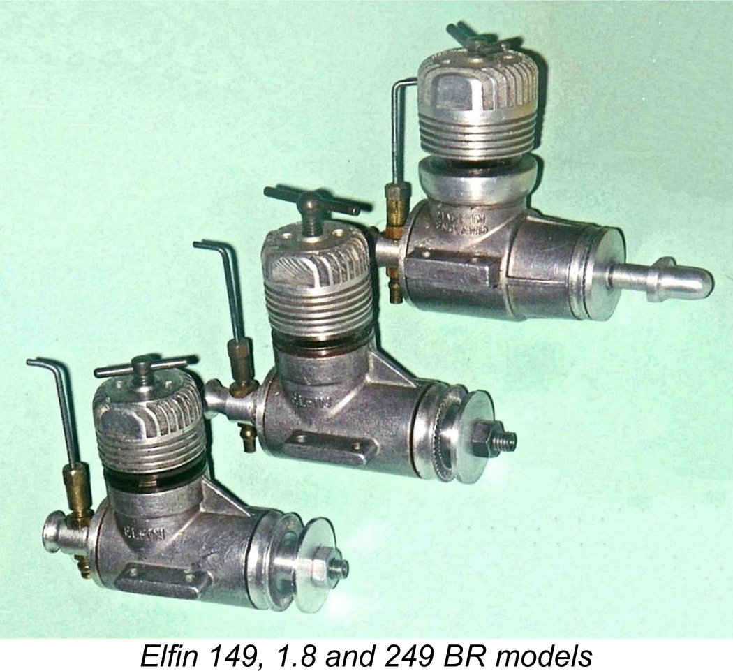 In this article we’ll share a comprehensive look at a series of British engines which seem to have enjoyed somewhat limited commercial success in their day but which were nonetheless recognized at the time as technological groundbreakers and are now highly regarded as collectibles - the Elfin twin ball-race reed valve models from Liverpool, England.
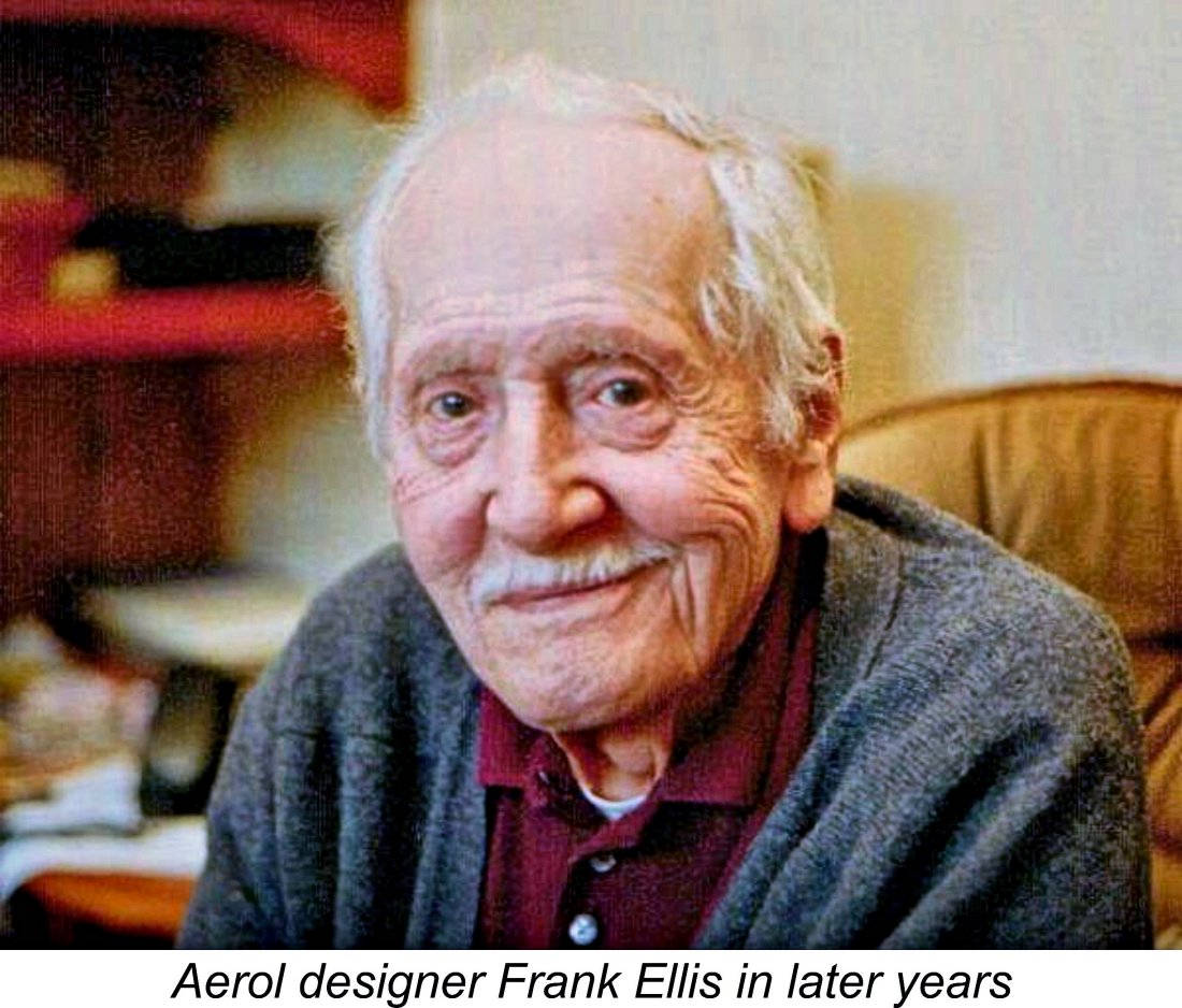 The greatest reward for undertaking research efforts of this nature comes when one of my readers is inspired to share additional information with me in order to make the story more complete. Following the initial publication of this article, Ron and I were most gratified to receive additional information from several individuals.
  The manufacturers of the Elfin engines were Aerol Engineering of Henry Street, Liverpool 13, England. Finding this location today proved to be a challenge because it turned out that there were in fact not one but two streets of that name in Liverpool! The more prominent one is located just up from the Salthouse Dock on the River Mersey. Today this street is dominated by apartments which are an element of the trendy City Centre area of Liverpool, but it still retains hints of its former industrial character. I initially assumed that this must have been the location of the Aerol Engineering works.
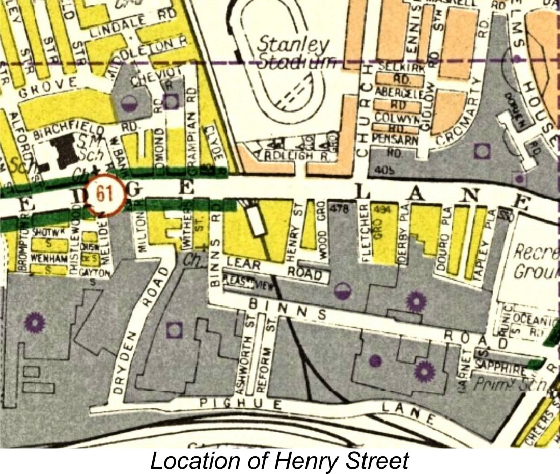 Shopping Park which began in 2010 at this location.
 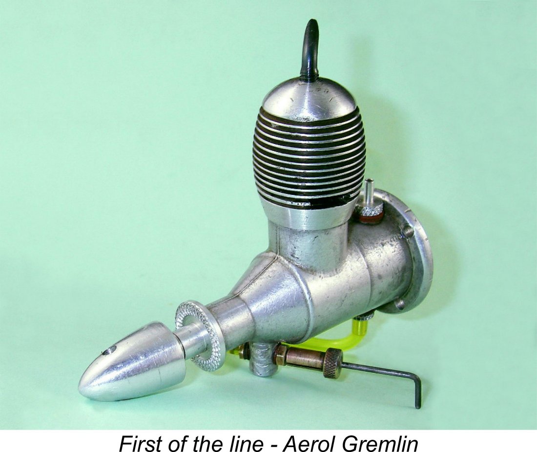 The first few models manufactured by the newly-formed company were released under the
 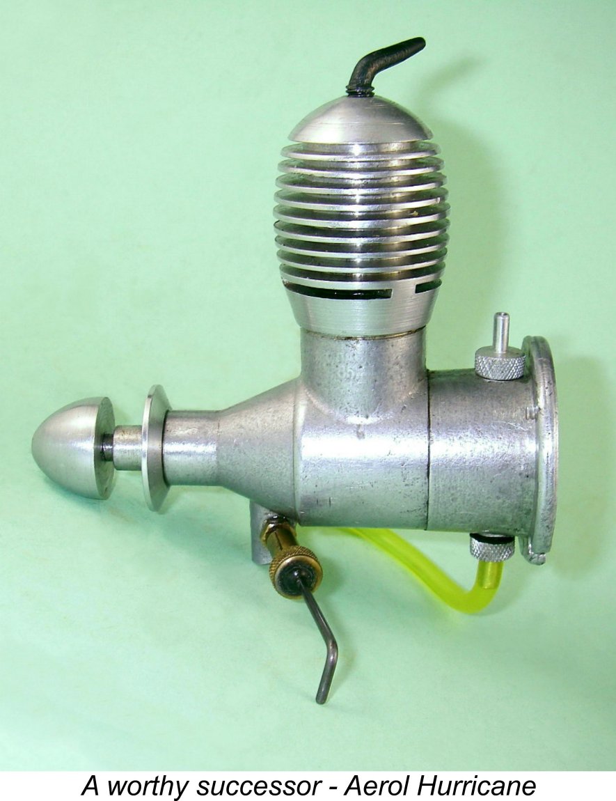 By 1948 the cylinder design of the Gremlin had been modified to utilize three exhaust ports in a radial arrangement combined with three Arden-style internal flute transfer ports. The rest of the engine was essentially unchanged. This revised model was known as the Aerol Hurricane. With a measured bore of 0.503 in. (12.78 mm) and a stroke of .609 in. (15.47 mm), the Hurricane had a displacement of 1.98 cc (0.121 cu. in.).
 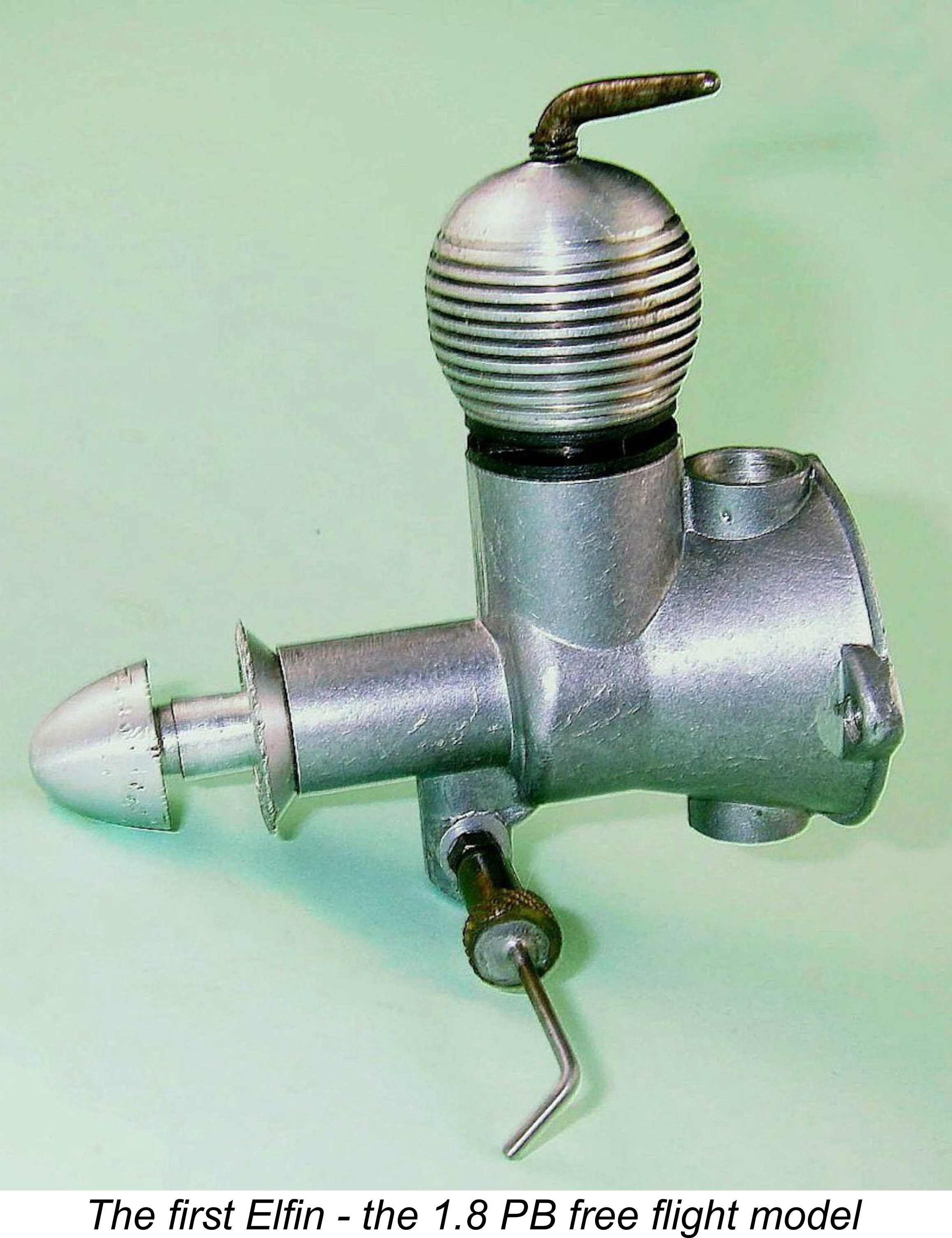 A story has circulated in the past that the rather odd-ball 1.8 cc displacement came about simply because Frank found some steel tubing that was easily machined into cylinders for an engine of that displacement. In his discussions with Jim Woodside, Frank provided some clarification of this point, stating that while the Elfin 1.8 was indeed the only model ever manufactured by Aerol Engineering using tubular steel stock for the cylinders, the tubing did not dictate the bore. The 1.8 cc displacement was an original design decision based upon Frank’s perception that an engine of that displacement made to Frank's design would strike the perfect balance between high power, compact size and light weight. The bore was actually a carry-over from the design of the Hurricane. The fact that the steel tubing in question was subsequently found to be useable in making the cylinders was purely incidental - the bore decision came first. Frank was very specific on this point.
 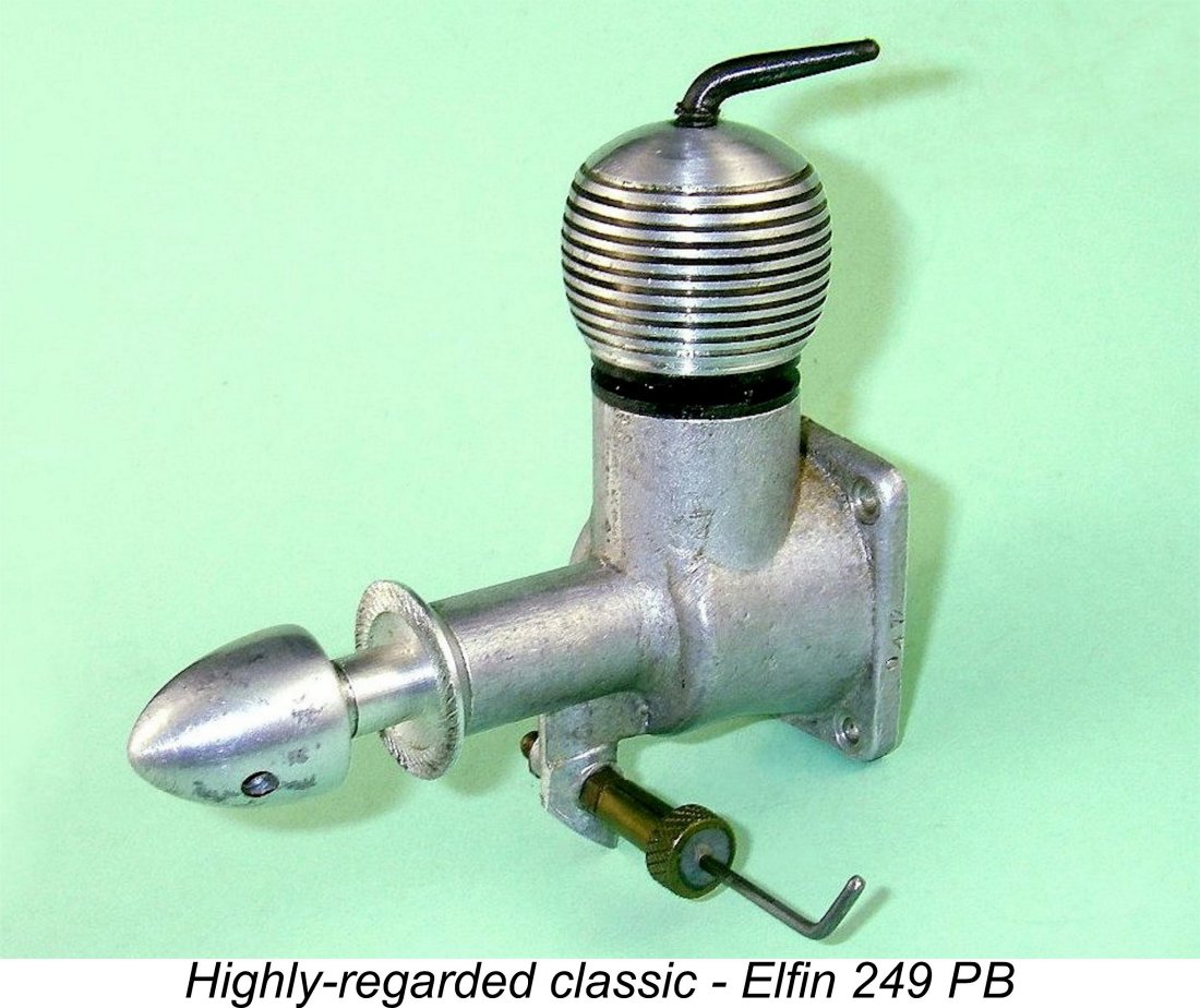 The company quickly built up a fine reputation for contest performance with this and the companion 2.49 cc plain bearing (PB) Elfin FRV offering. Like their Gremlin and Hurricane predecessors, the original Elfin PB models featured gravity die-cast cases, radial mounting, "Arden" porting and up-draft FRV induction at a time when the British market was still largely dominated by side-port engines. They were both powerful and lightweight by the standards of the day, quickly becoming accepted as the new benchmarks for British competition diesels. Frank was evidently able to sell the engines as fast as he could make them.
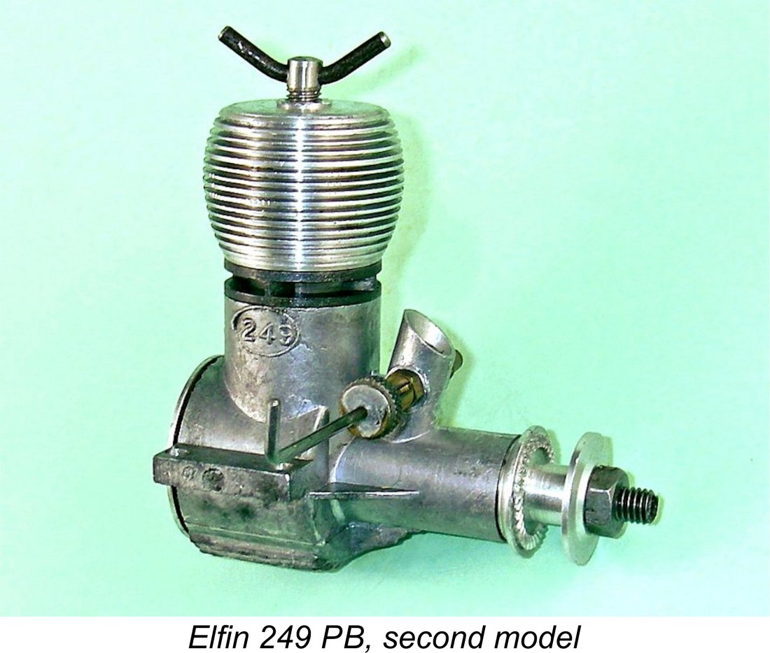 Britain. They also reverted to more conventional down-draft carburetors while retaining the FRV induction of their predecessors. By the evolving standards of the time, they were considerably more conventional designs than their radial mount ancestors.
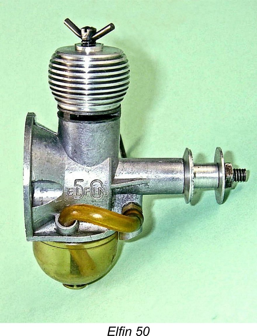
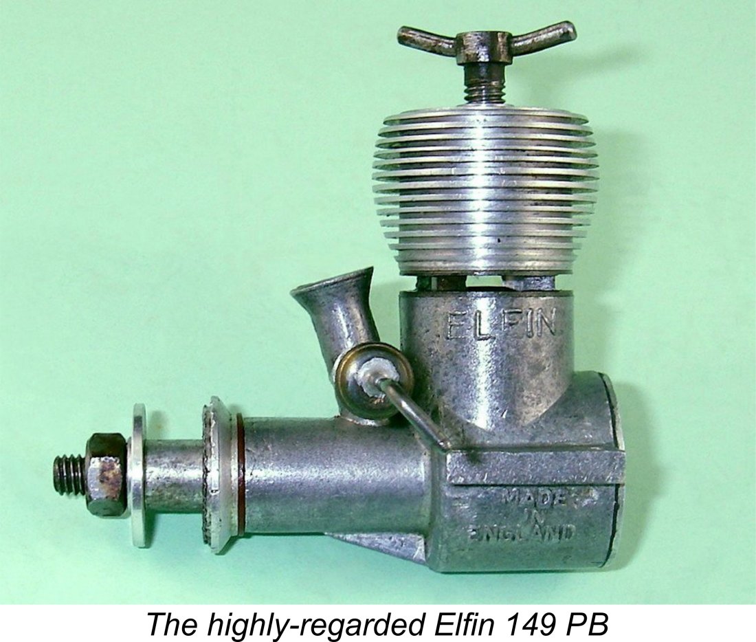 Despite the notable achievements summarized above, it's clear from reading contemporary commentaries that the revised beam mount Elfin plain bearing models were not greeted with universal acclaim, in particular the 249 model. There were some documented quality control issues with these models (see later discussion) and while the 1.49 cc model had no Elfin predecessor in its displacement category and was generally considered to be the performance leader in its class at the time, many modellers of the day openly mourned the passing of the radial-mount 249 model of 1949, feeling that its beam-mount replacement fell short of matching its effectiveness. Indeed, published test figures confirmed that the beam-mount model failed to match the performance of its radially-mounted predecessor.
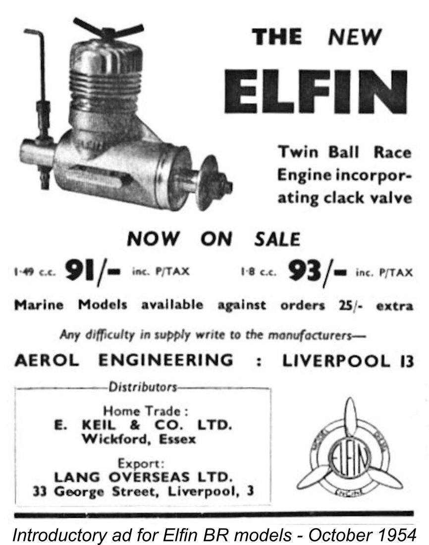 The first advertisement for the Elfin ball-race (BR) series appeared in the October 1954 issues of both "Aeromodeller" and "Model Aircraft" magazines. This initial offering included 1.49 cc and 1.8 cc versions - the companion 2.49 cc BR model first went on sale considerably later, as we shall see in due course.
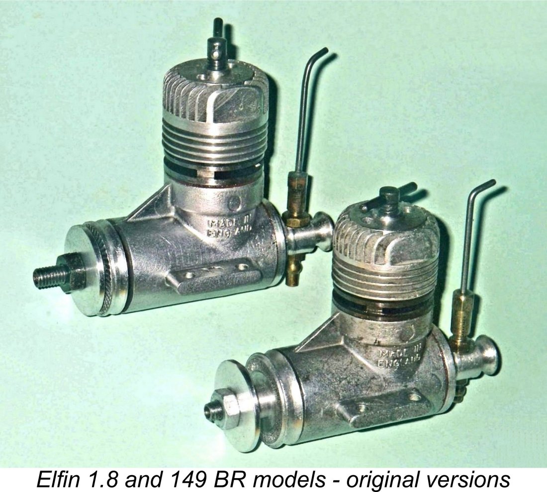
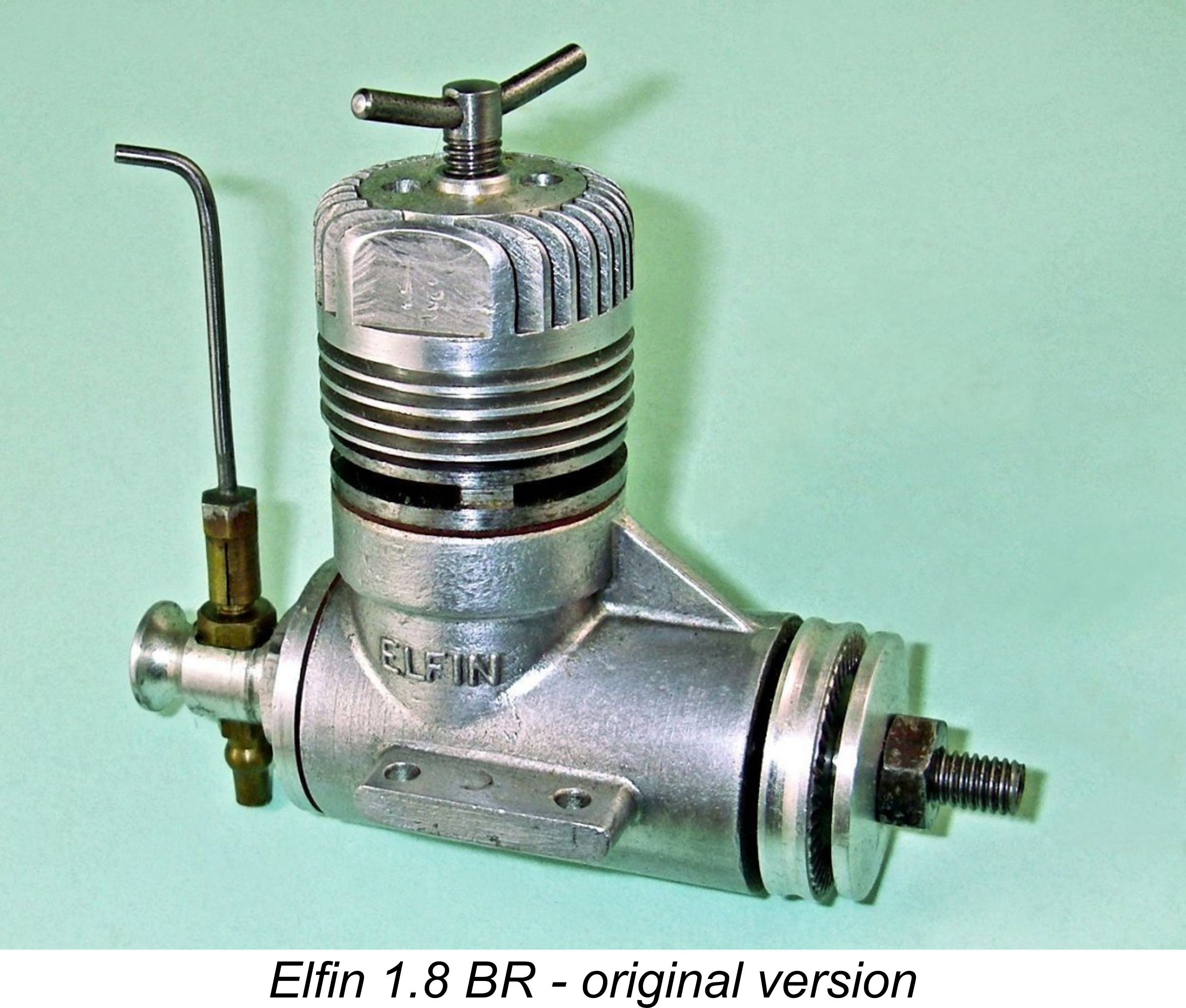 This approach naturally resulted in a slightly taller engine. More significantly, it substantially increased the non-commonality of parts and hence the cost of production. Although the same basic casting was used, this had to be further machined to accommodate the longer stroke of the 1.8. In the end, the piston/cylinder sets, the cooling jackets, the crankcases, the crankshaft and the conrod all had to be manufactured specifically for the given displacement - in fact, the only interchangeable finished components were the complete reed valve induction assembly, the comp screw, the piston, the gudgeon (wrist) pin, the ball races and the prop mounting hardware! It’s thus not possible to convert one model into the other.
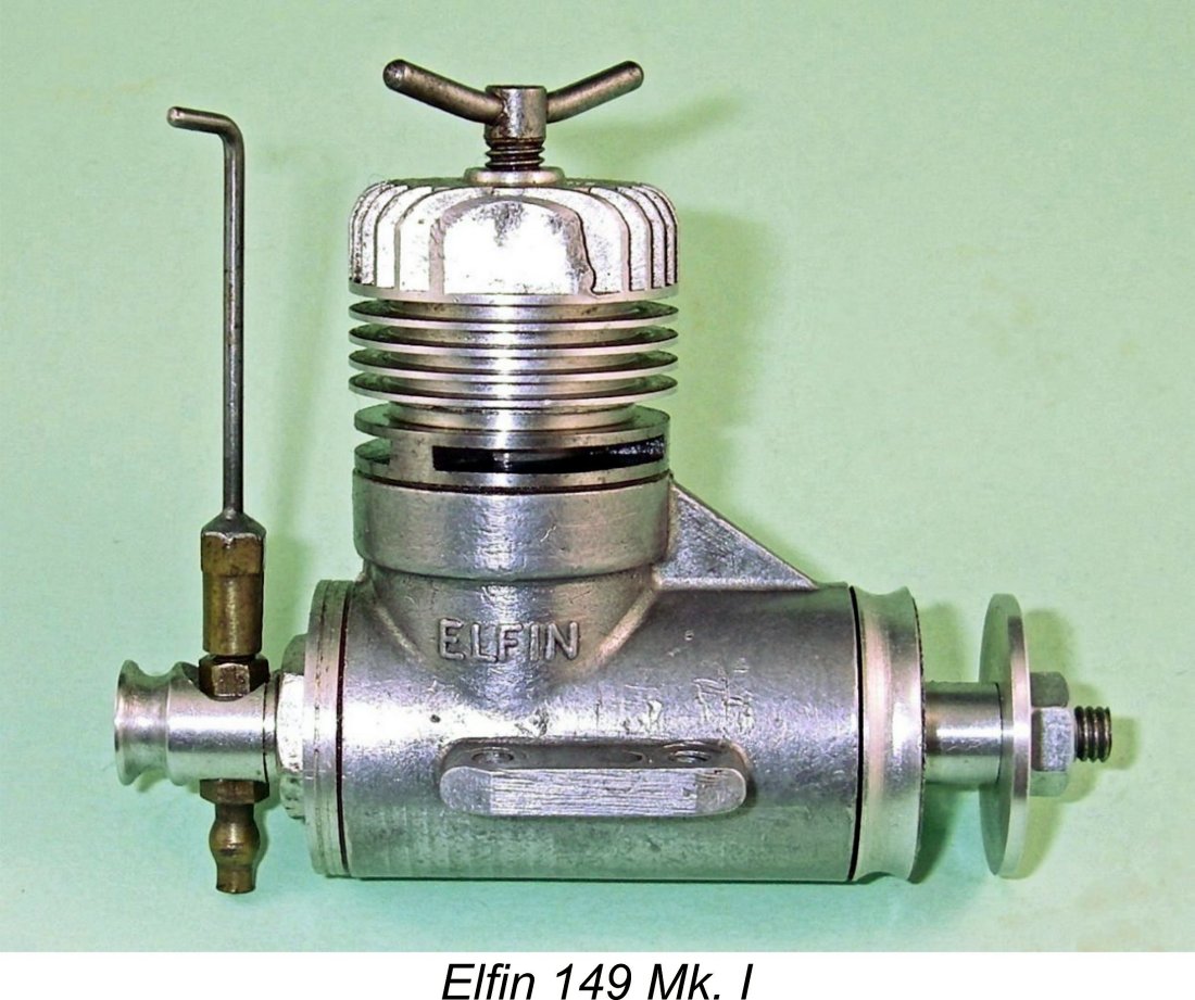 It may be deduced from this that Frank Ellis had never fully embraced the short-stroke approach to model engine design, hence being happy to return to his original long-stroke geometry in the new 1.8 cc model even if it meant the loss of an opportunity to maximize the standardization of components. The two 149 models (plain bearing and ball race) were to prove to be the only short-stroke designs ever to be manufactured by the company.
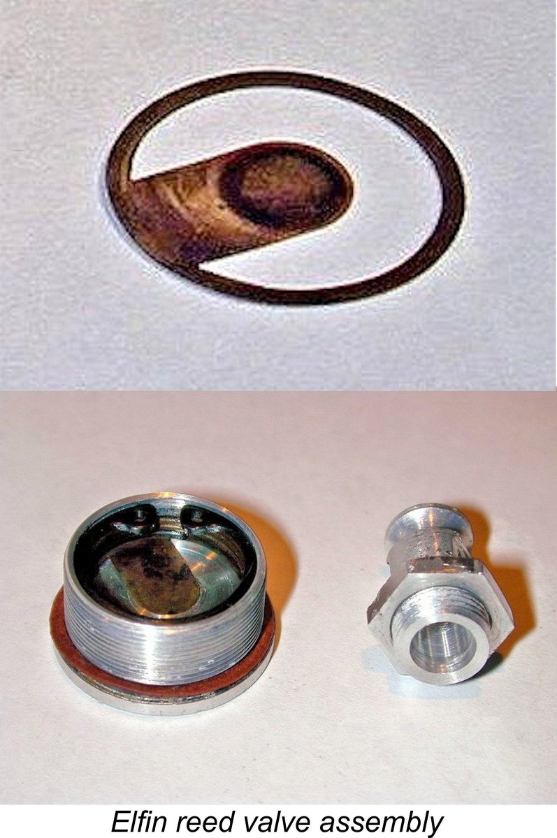 On the induction side, the engines employed what the introductory advertisements referred to as a "clack valve", being the first English production engines to feature this type of induction. Indeed, at the time of their introduction they were the only commercially-produced clack valve diesels in the world. This induction system (variously called flutter-valve, clack valve, clapper valve and reed valve) had gained popularity in the USA through its successful application to the Cox Space Bug and Thermal Hopper ½A models. I prefer the reed valve term myself.
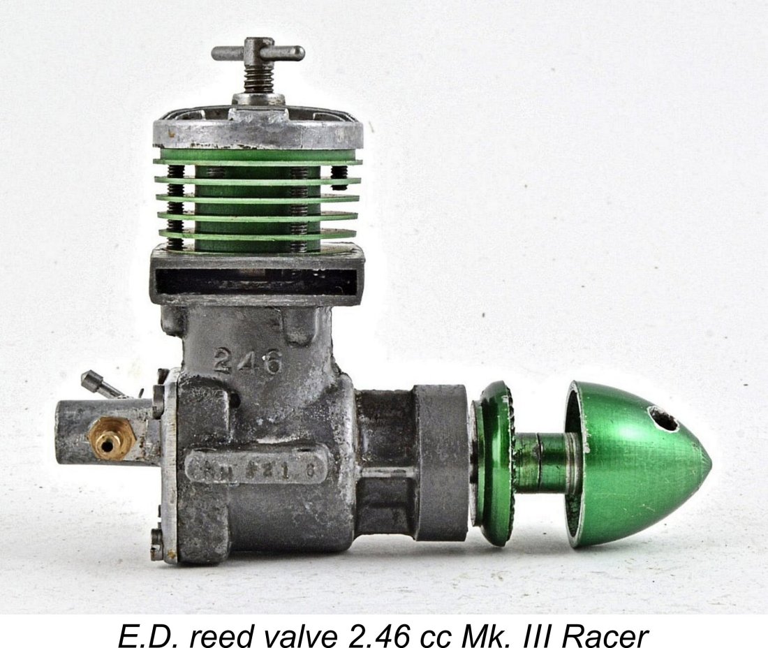
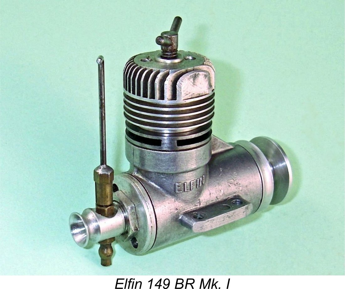 The initial appearance of one of the Elfin BR models in a published test report came in the form of Ron Warring's
 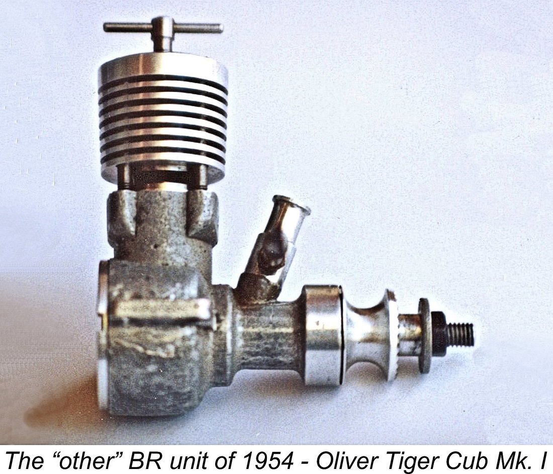 As the first commercially-produced twin ball race 1.5 cc diesel (the Oliver was an individually custom-built motor), the Elfin pointed the way ahead but evidently defeated some peoples’ ability to assess its characteristics on a more rational basis. Its reputation evidently suffered as a result of its being the first series-produced British 1.5 cc twin ball-race diesel, a circumstance which would logically lead one to expect that it would re-define weight norms in its category. The fact that it was criticized for doing just that is highly unfair to its reputation.
 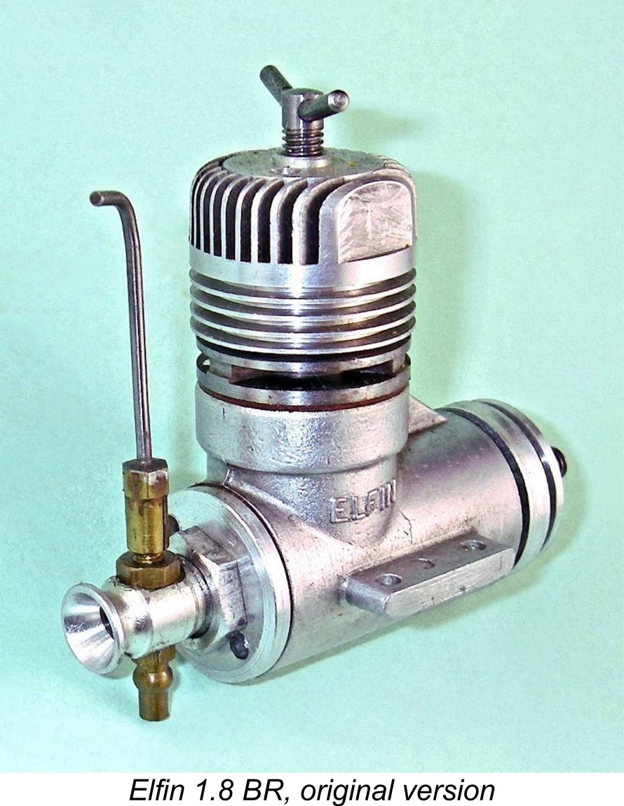 Turning now to the 1.8 BR, this model did not attract anything like as much sales attention as its smaller counterpart, quite understandably in view of its rather odd-ball displacement by mid 1950’s standards. This of course explains why the 1.8 BR model is far less common today than the 149 BR. "Aeromodeller" never even bothered to publish a test of this model, but curiosity drove "Model Aircraft" to evaluate the engine in a
 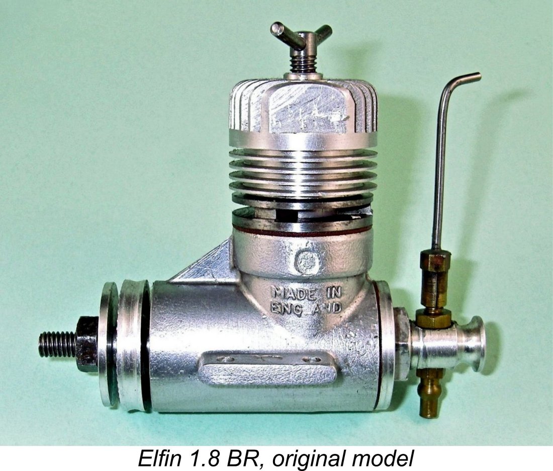 Once again, Chinn praised the engine's starting and running qualities, although he did note that quite careful adjustment was required to obtain best performance, He was able to measure an output of 0.186 BHP @ 13,000 rpm, compared with the 0.165 BHP @ 14,000 rpm measured for the better of his two examples of the 149 BR. The measured specific output of the 1.8 BR was 102 BHP per litre which, although a little down on the 110 BHP per litre figure obtained for the 149 BR, still exceeded the magic 100 BHP per litre figure which was then the accepted standard for over-the-counter competition diesels. How times have changed!
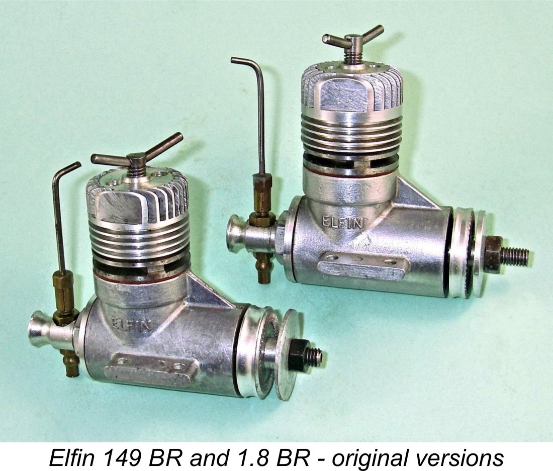 The Elfin 149 and 1.8 BR models are essentially identical in terms of their construction. Accordingly, the following description applies to both models except where noted. The various component views which appear here all came originally from Ron Chernich.
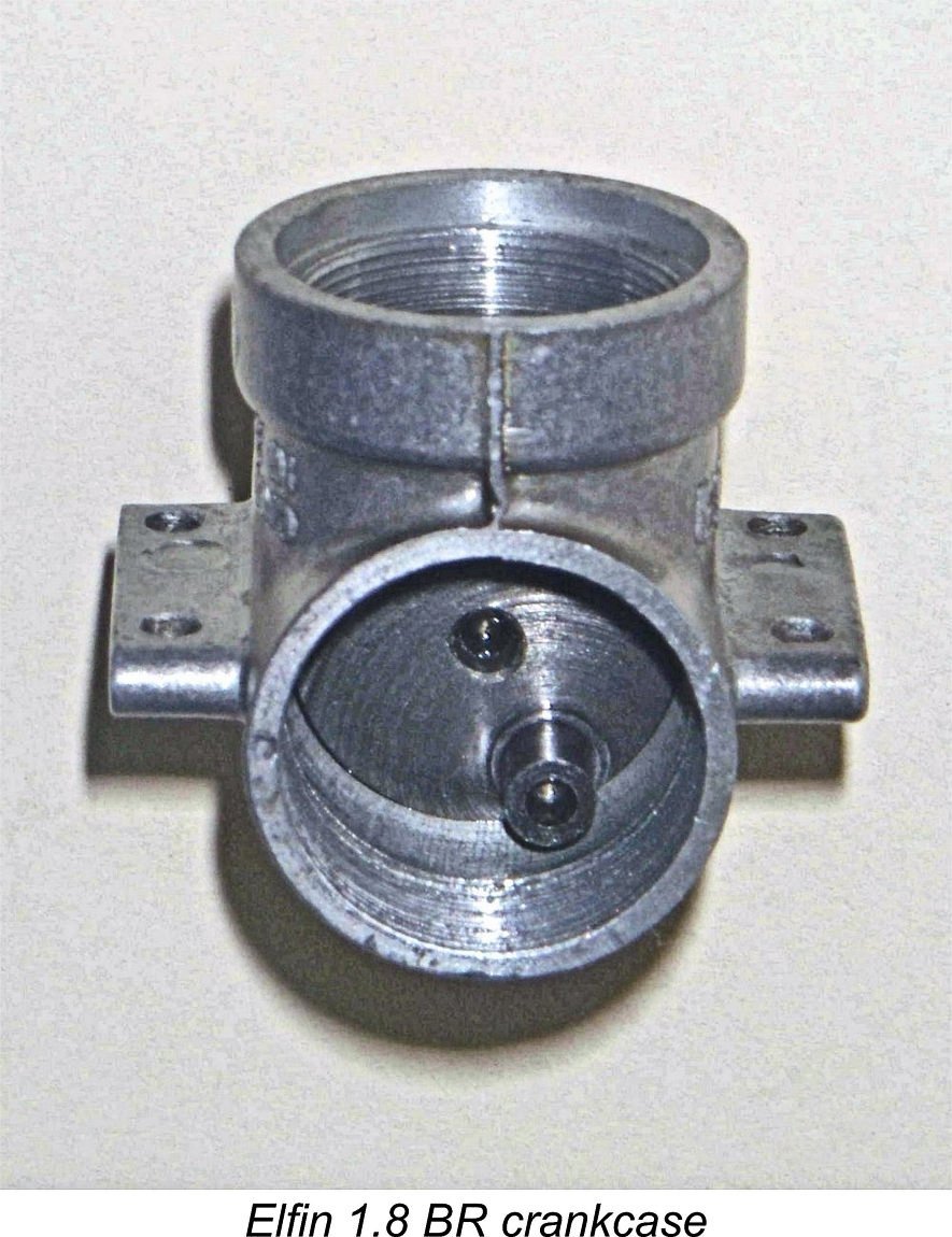 The top few millimeters of the crankcase casting are internally relieved to create an unthreaded annular passage around the outer cylinder wall at transfer port level, exactly as in the American OK Cub engines. This annular channel is clearly seen in the accompanying image. It feeds the cylinder through three large 5/32 in. diameter transfer ports drilled at an angle into the columns separating the three exhaust slits (i.e., "Oliver" style peripheral porting). There is a very substantial overlap between the exhaust and transfer ports, reducing the blow-down period to a minimum. It is the ability to incorporate such an overlap that makes the Oliver system so effective.
 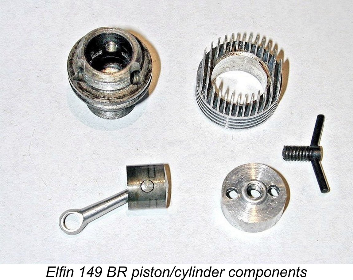 The deck heights of the 149 and 1.8 units are different. For this and other reasons (see below), the finished cases of the two models are not directly interchangeable, although they are based upon the same original casting. To maintain similar timing with a longer stroke, the ports of the 1.8 cylinder were necessarily set somewhat higher than those of the 149 version. This was achieved in part by machining the deck height of the crankcase a little higher for the 1.8 and in part through the use of a thicker exhaust flange on the 1.8 cylinder. Based on rough measurements taken from several examples, it appears that the exhaust and transfer periods of the two models were approximately the same, but the 1.8 had a somewhat longer sub-piston induction period. Peter Chinn specifically noted the latter feature in his test report, along with the greater deck height.
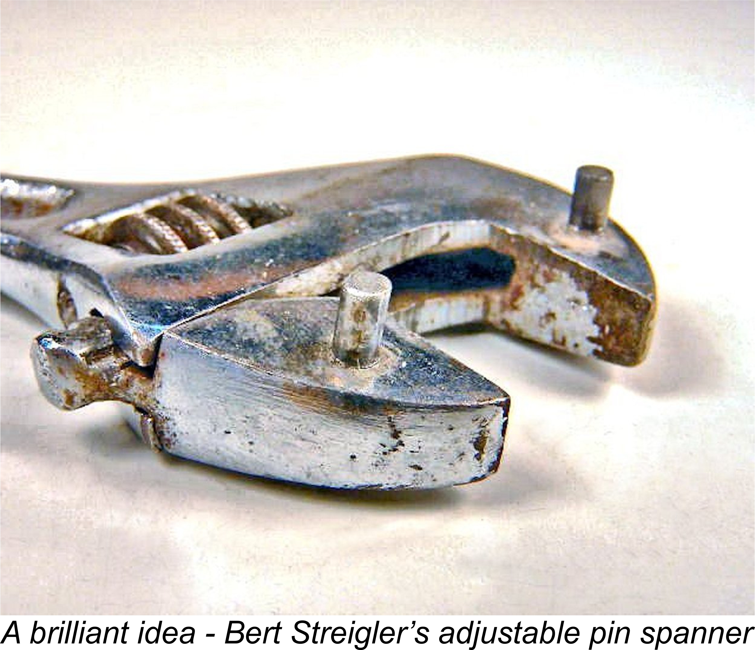 The compression screw threads into the retaining cap, which is drilled for a pin spanner. As the engine was supplied without such a tool, Warring suggested using the tips of a pair of needle-nosed pliers for tightening. AAARRRGGGHHH!! No doubt many surviving examples bear mute testimony to this officially-endorsed butchery. The backplate too is tightened by a pin spanner, but requires a different pin spacing, so what is really required here is the late Bert Streigler’s
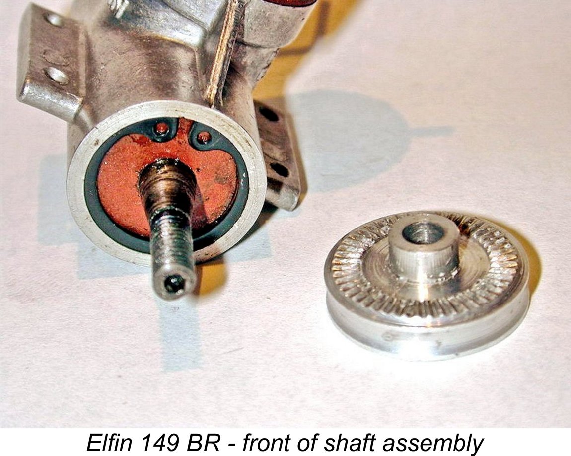
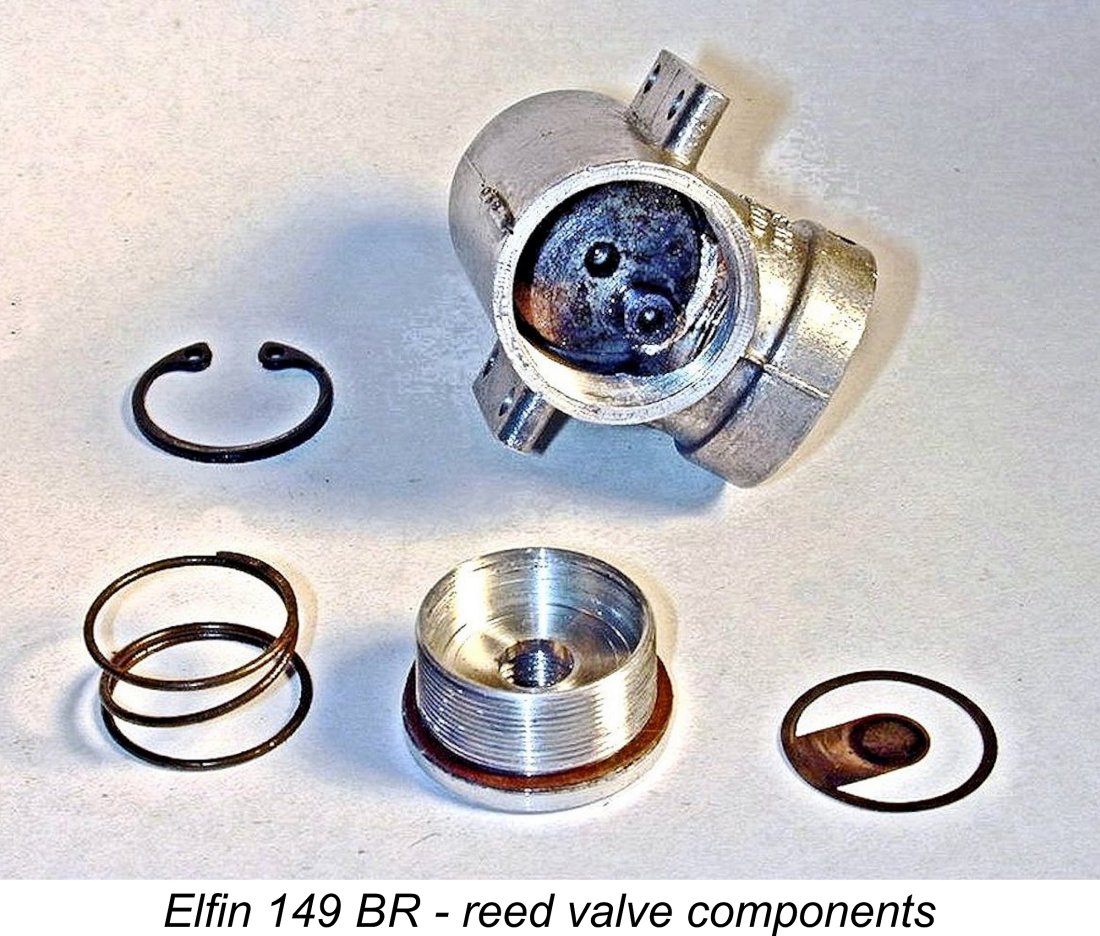 At the rear of the engine, the phosphor-bronze reed is a rather intricate and delicate 0.002 in. thick stamping having a continuous circular outer annulus with an internally-protruding "flap" which serves as the actual reed. The outer annulus is tensioned against the inner face of the backplate recess by a relatively strong coil spring whose faces have been ground flat. Another circlip keeps everything in place. The tension of the spring is sufficient to prevent it from participating in the induction process, leaving all of the opening and closing movement to be accomplished by the flap.
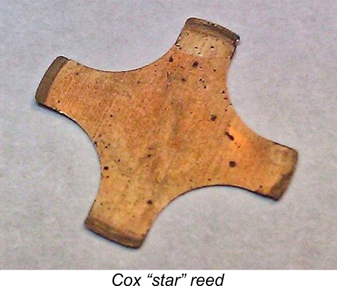 In terms of longevity, I view this reed design as one of the engine's Achilles Heels. The amplitude of the reed’s movement is unrestrained in any way, while it features sharp 90 degree corners at the points where its edges intersect with the firmly secured circular outer annulus. These will inevitably create cyclic stress concentrations at those points when the engine is running - a tailor-made recipe for metal fatigue failure. In my opinion, extended use of the engine is almost certain to cause the reed to fail at the junction points. I have actually had two used examples through my hands which had suffered this very kind of failure. A Cox-style four-armed “star” reed with no sharp corners would be far better suited to the task.
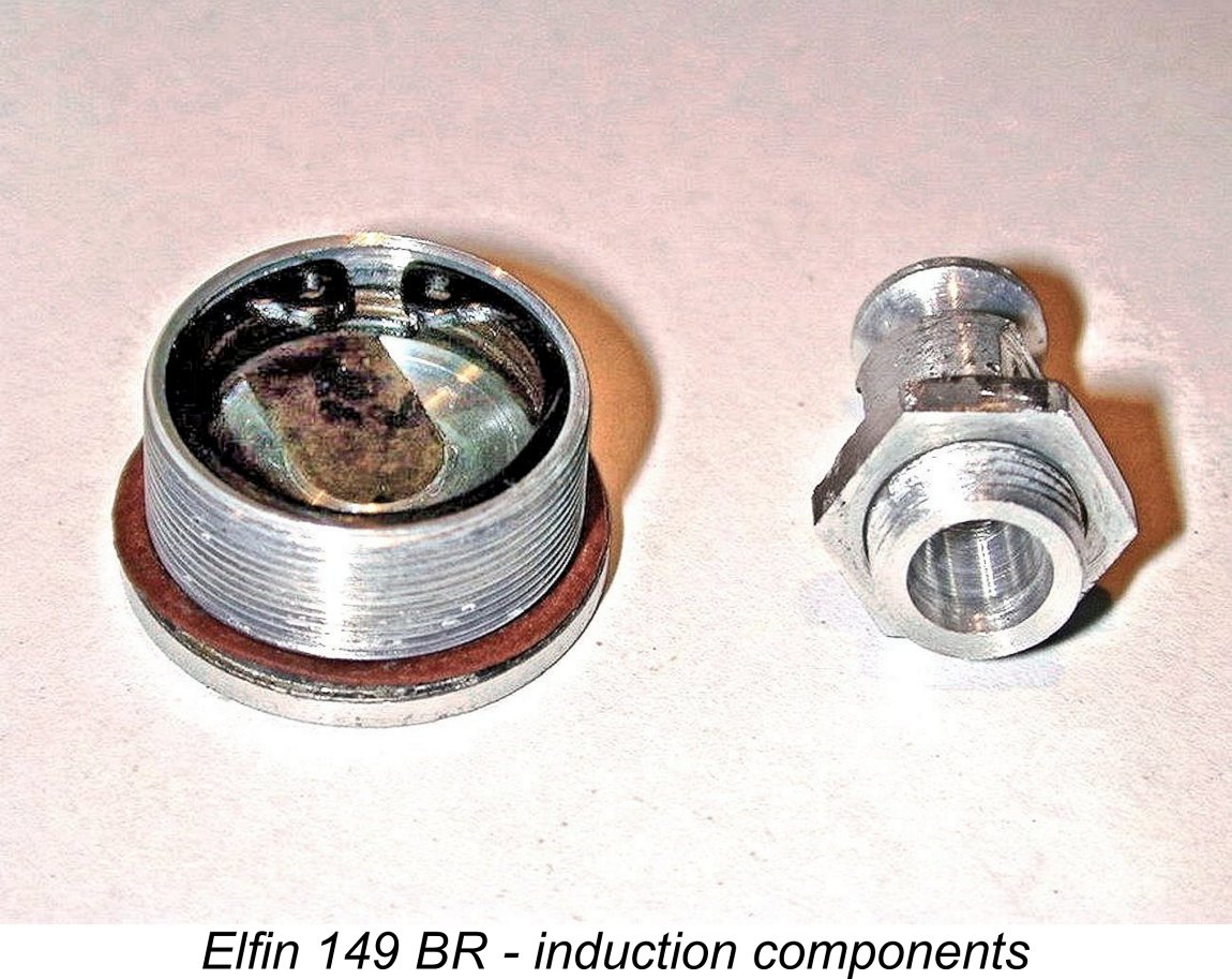 The screw-in aluminium venturi is centrally located in the backplate and has a true venturi shape. That is, the "exit'" side has a more acute taper than the "entry" side. A strong concern for good suction is implied here. The venturi throat is parallel at the point where the spray-bar passes through. The venturi assembly is locked by an aluminium nut and can be rotated to whatever angle is most practical for the installation - a very useful feature.
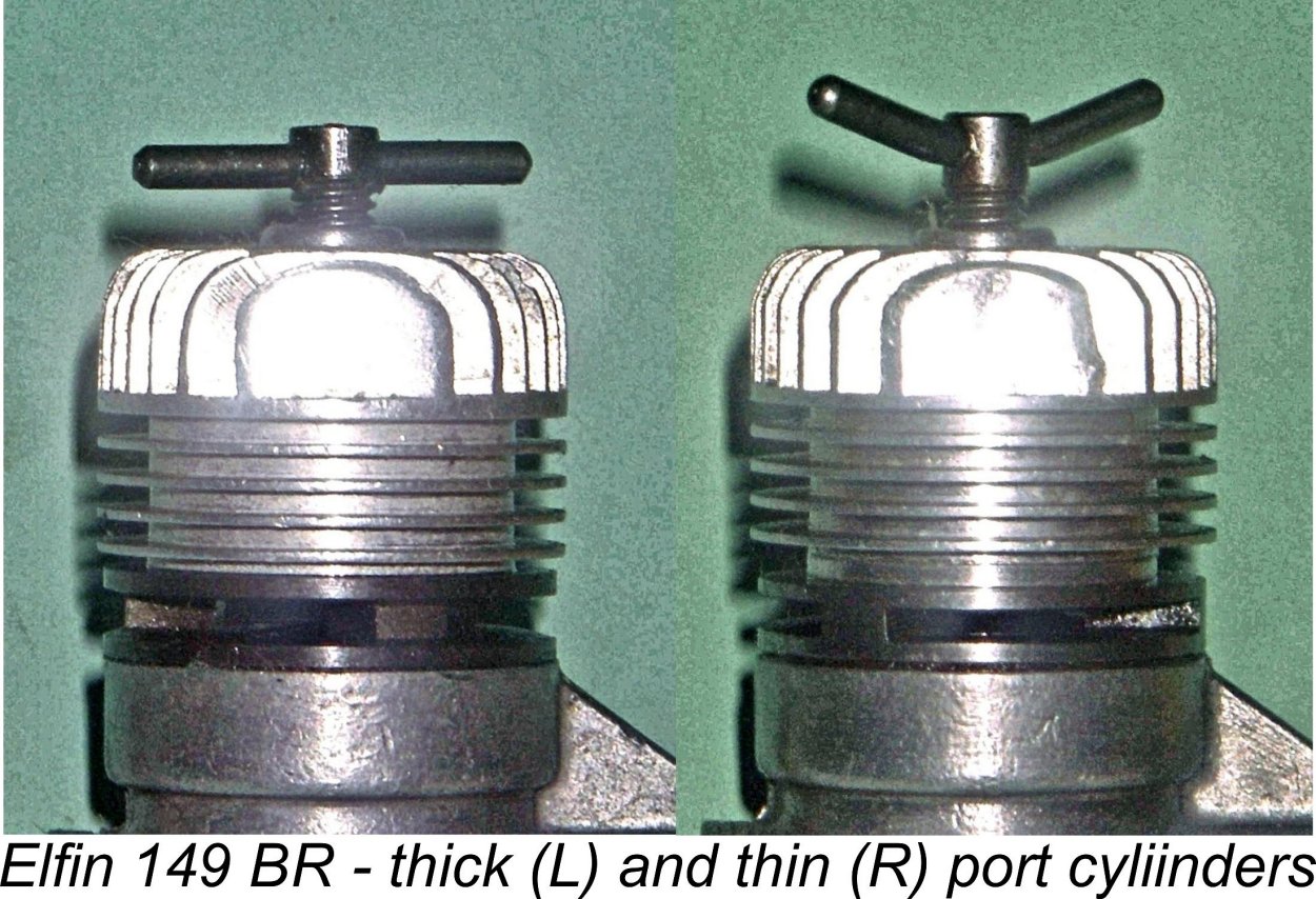 As we shall see, the original version of the Elfin 149 BR and the companion 1.8 BR model were both in production for considerably less than two years. During that period, there was at least one minor variation in the 149 BR Mk. I model. Two distinct cylinder configurations have been recognized, each having differing exhaust flange thicknesses. The more common and seemingly original variant features a flange having a nominal thickness of 0.1875 in. with sawn exhaust ports having a height of 0.082 in. The less common "thin port" variant has a nominal flange thickness of only 0.140 in., with sawn exhaust ports having a height of 0.072 in.. Clearly a different tool was used to cut the exhaust ports in the two variants.
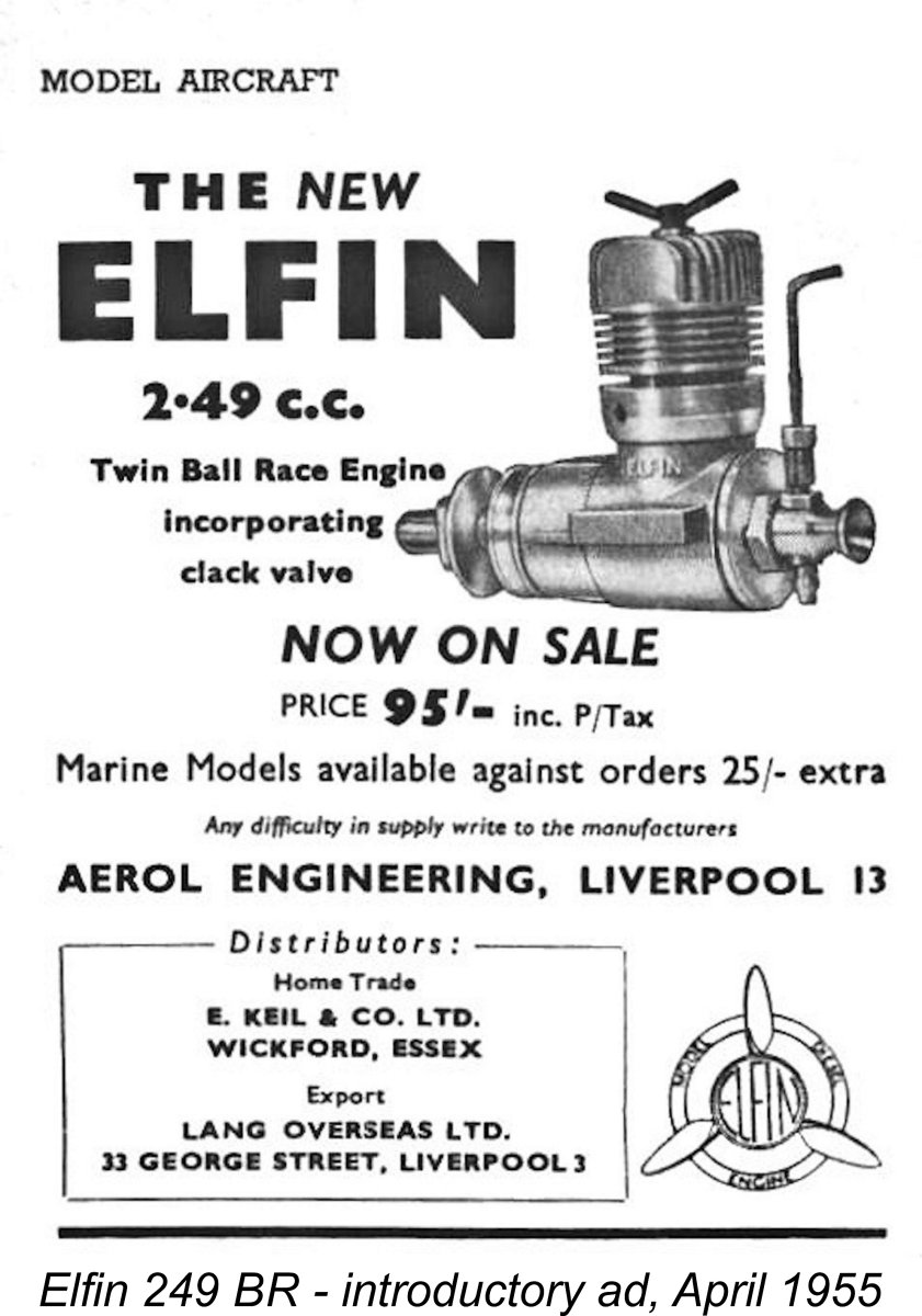 During the initial period in which the 149 and 1.8 BR models were being launched upon the market, the manufacturers evidently continued to offer their established 249 beam-mounted plain bearing model. However, plans were well advanced to replace this model too with a completely revised design patterned on the smaller BR models already in production.
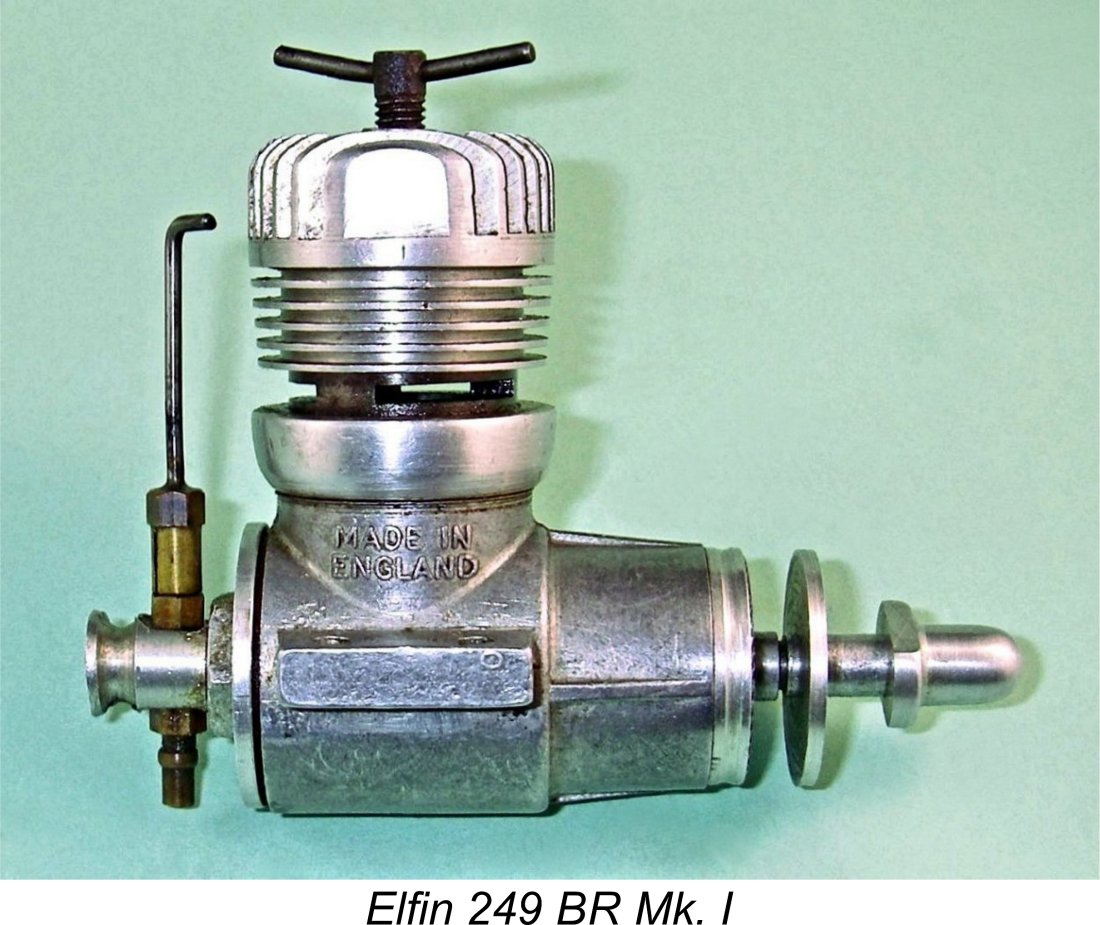
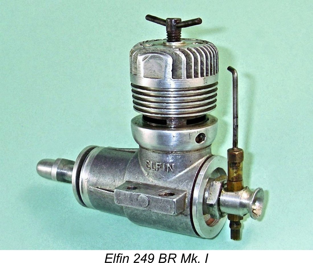 Internally, the bypass arrangements had changed significantly. The Oliver-style transfer porting was unaltered, but the makers had evidently concluded that a less restrictive bypass system was required. To this end, they had eliminated the former channels in the outer cylinder wall in favor of three far roomier smooth-walled bypass passages formed internally in the upper crankcase wall.
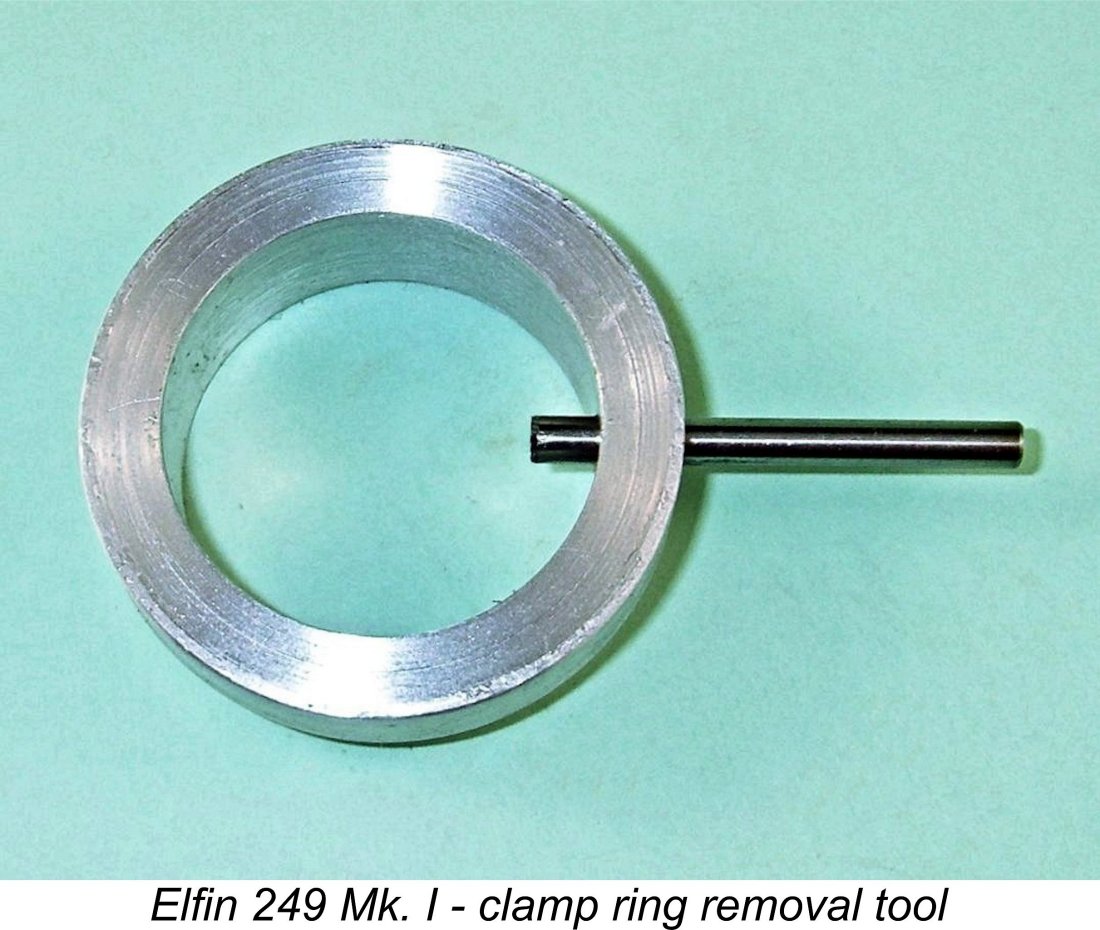 It's essential to ensure that the cylinder is in the correct alignment with the crankcase when tightening the clamping ring down fully. It’s also essential in the interests of conservation to use the correct tool to either tighten the clamp ring or remove it for disassembly. No vice-grips, please - use an easily-made circular ring-spanner that engages with the radial hole in the clamp ring perimeter which is provided for the purpose. This hole is clearly visible in the above image.
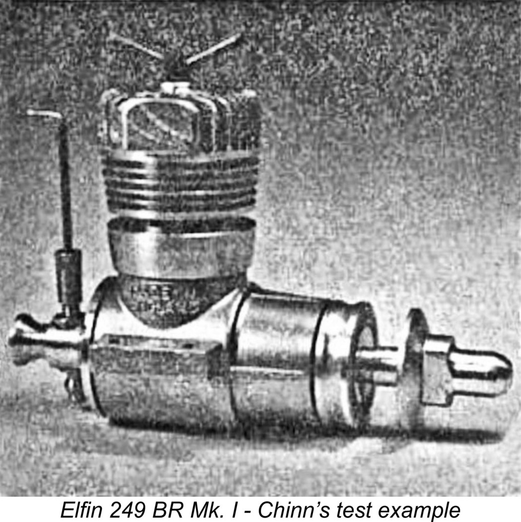 In other respects, the new 249 BR was more or less a scaled-up version of its smaller siblings. The reed valve design was essentially identical and the sub-piston induction used on the smaller designs was retained also. As suggested earlier, the reed design appears to have been inherently prone to fatigue failure in service - my example arrived with a broken reed. I replaced this with a re-designed component of my own making which should outlast the original by a considerable margin.
 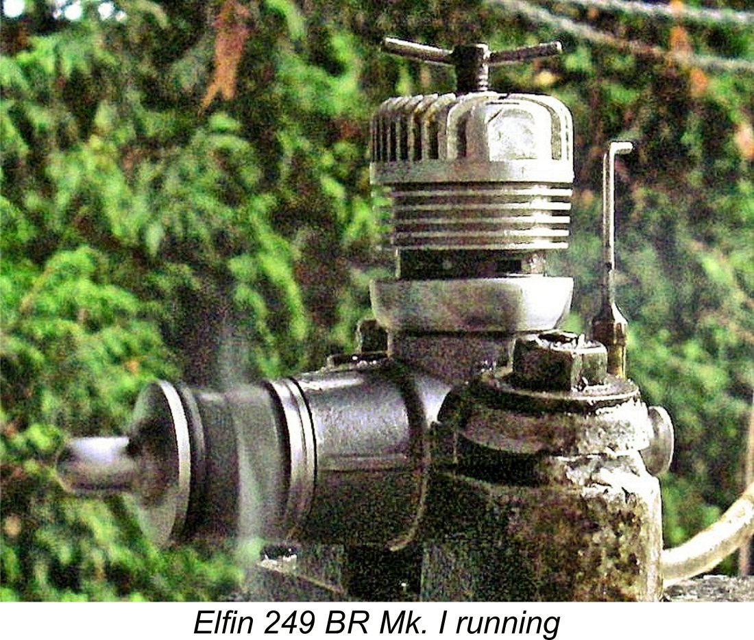 Here I can only comment that my own well-used example of this model with its modified reed valve is a very easy starter and a fine runner. Moreover, it develops considerably more power than the units tested by Chinn and Warring. I measured a peak output of 0.292 BHP @ 12,100 rpm. Admittedly this was achieved using my replacement reed valve, which may have affected performance somewhat. Perhaps my re-designed reed valve works better than the original ……… I’d like to think so, anyway! A
 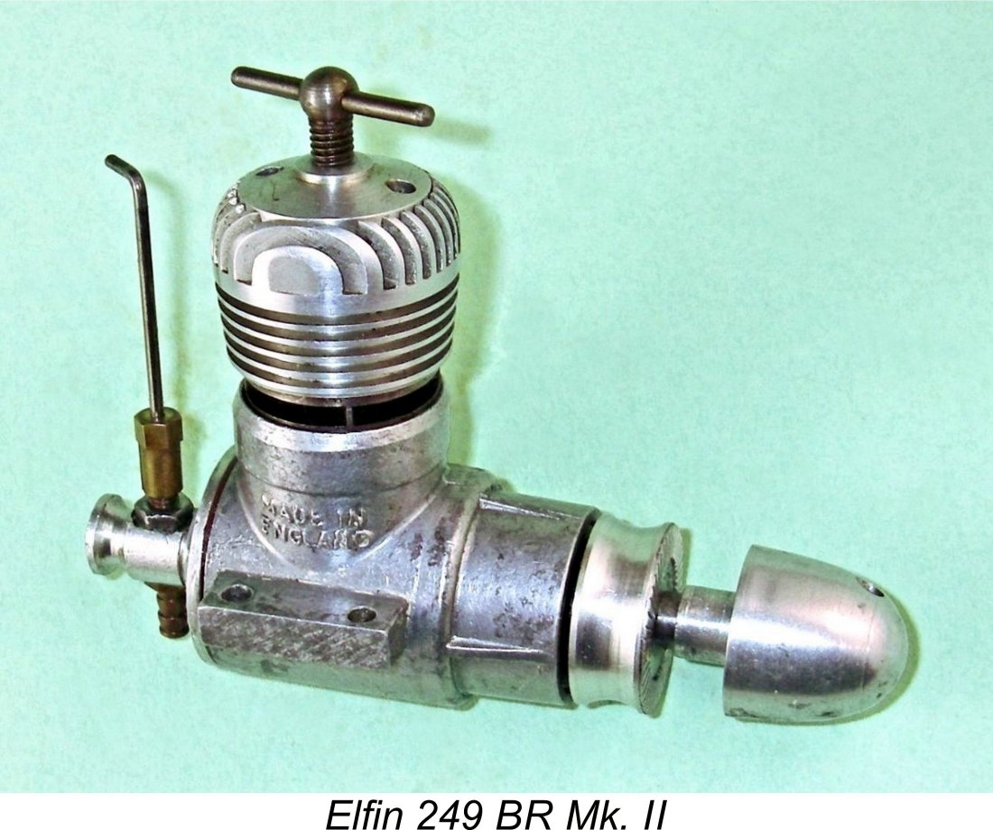 It can't have taken long for Aerol Engineering to realize that something fairly drastic would have to be done if their new 249 BR model was to remain in production. Sales of the original 249 BR Mk. I model just described had been understandably slow given its relatively high price, mediocre reported performance and limited availability. The choice was starkly simple - either improve performance (and if possible reduce costs at the same time) or abandon the 249 BR design altogether.
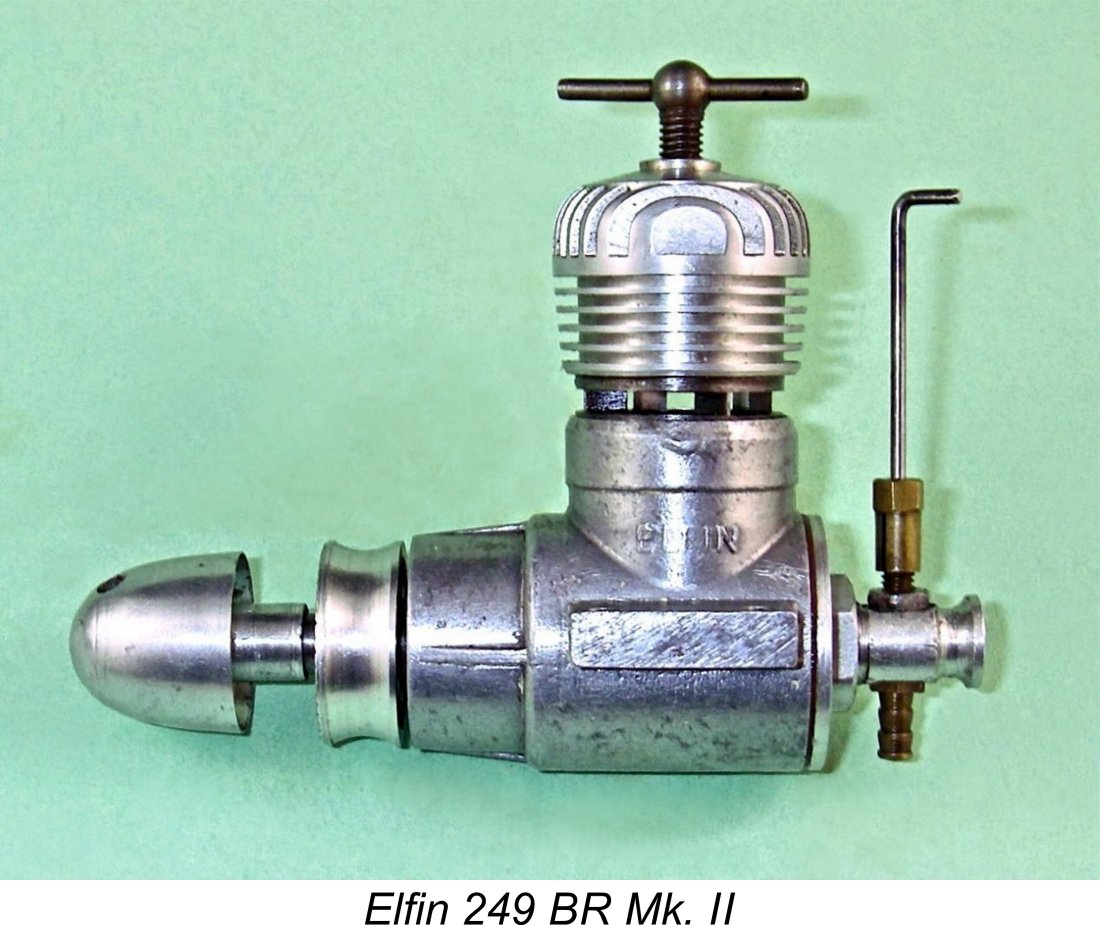 The revised 249 BR model (which is generally identified as the Elfin 249 BR Mk. II) appears to have been motivated as much as anything else by a desire to cut manufacturing costs. The former drop-in cylinder with "dog collar" retaining ring was dropped in favor of a reversion to the far simpler screw-in cylinder used on the smaller BR models. Naturally, this meant that the alignment of the cylinder when fully tightened could no longer be guaranteed, but the revised bypass arrangements using internally-machined transfer flutes in place of the former Oliver-type porting rendered this unnecessary in any case.
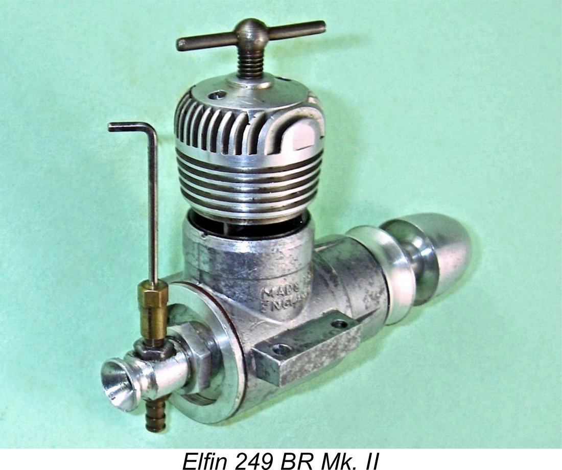 Apart from the changes noted above, the engine was very similar to its predecessor. The case was more or less identical apart from the absence of the external threading for the now-absent cylinder retaining ring. The reed valve unit too was retained unaltered apart from the fact that two superimposed reeds were now used instead of one, presumably to reduce blowback.
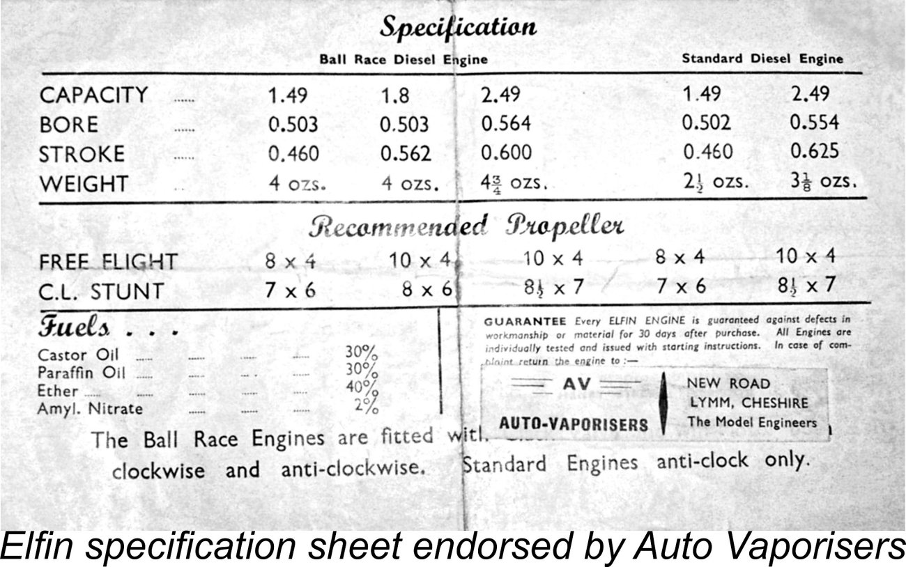
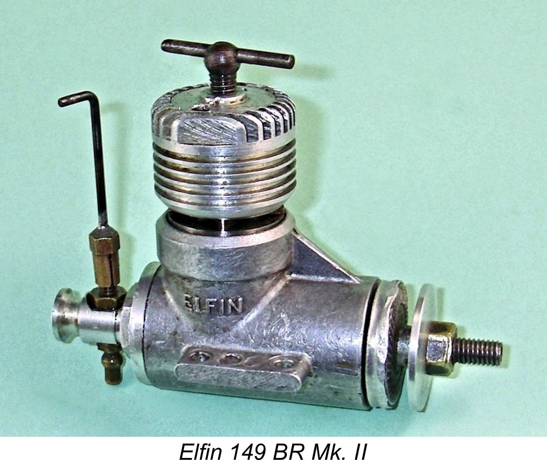 We now come to the point in our story which appears to have been incompletely documented in the past. The revised May 1956 version of the 249 BR model just described is of course quite well-known. What seems to be less widely appreciated is the fact that both the 149 BR and 1.8 BR models were also revised at more or less the same time.
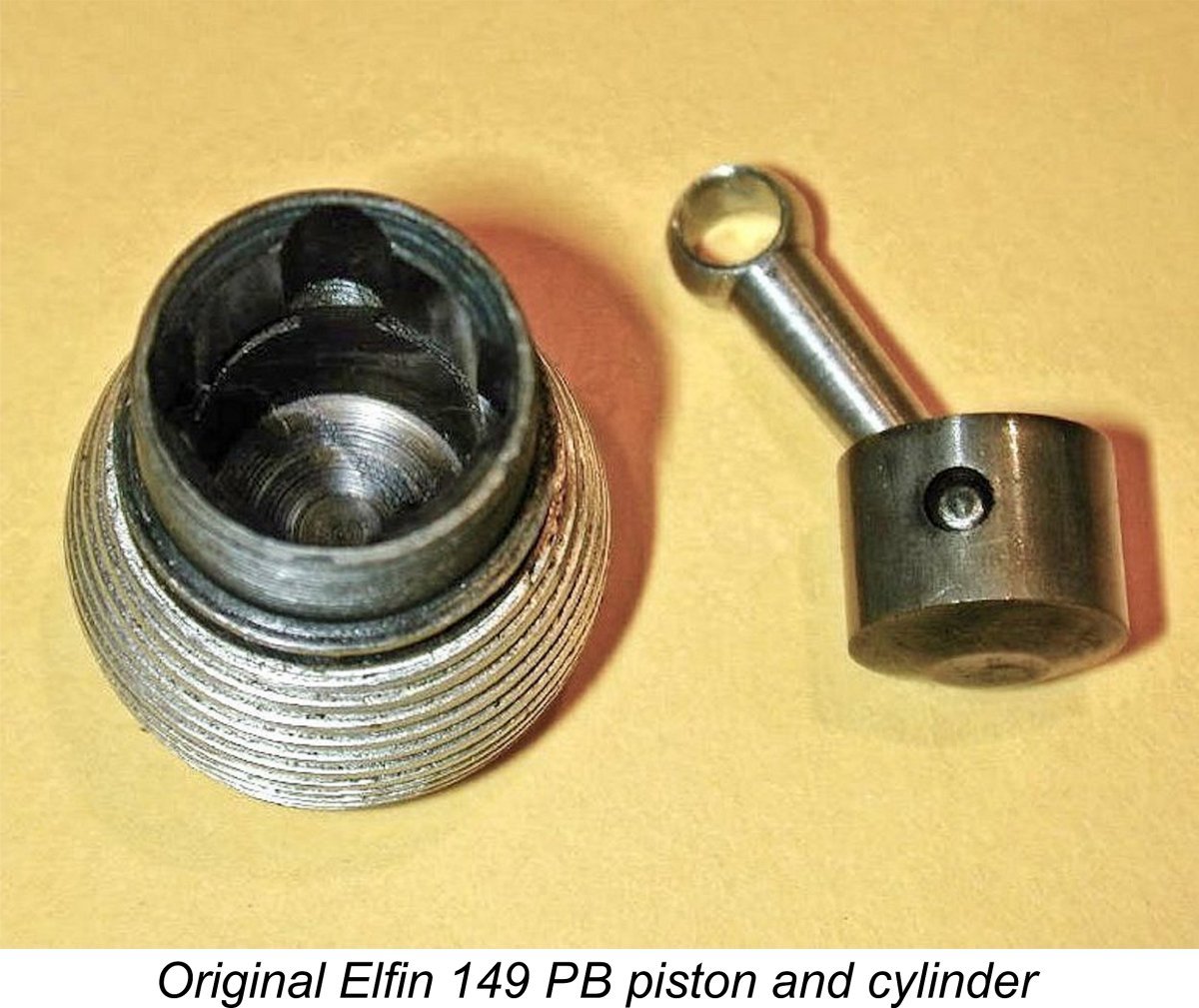
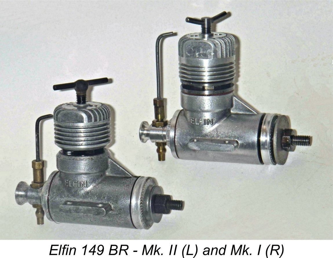 The same type of revised cooling jacket was also applied to the 149 BR model. As with the 249 BR, the new jacket incorporated a chamfered lower edge and thicker vertical top fins, the extra thickness once more being accommodated by the omission of one fin. The top fins were also cut shorter, resulting in a reduction in the engine’s height. As the accompanying image will confirm, the 149 BR Mk. II was noticeably more compact than the Mk. I version.
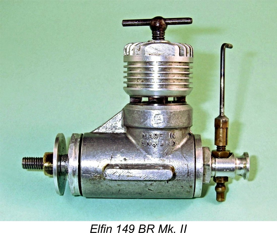 At this point, I have to interject a few comments based upon my own experience with this model. Some years ago, I acquired a well-used but still complete example of the later 4-port Elfin 149 BR which had suffered the common occurrence of a broken reed valve. It is this example that is illustrated here. I eventually got around to replacing the reed with a re-designed component of my own making, subsequently putting the engine through its paces on the test bench.
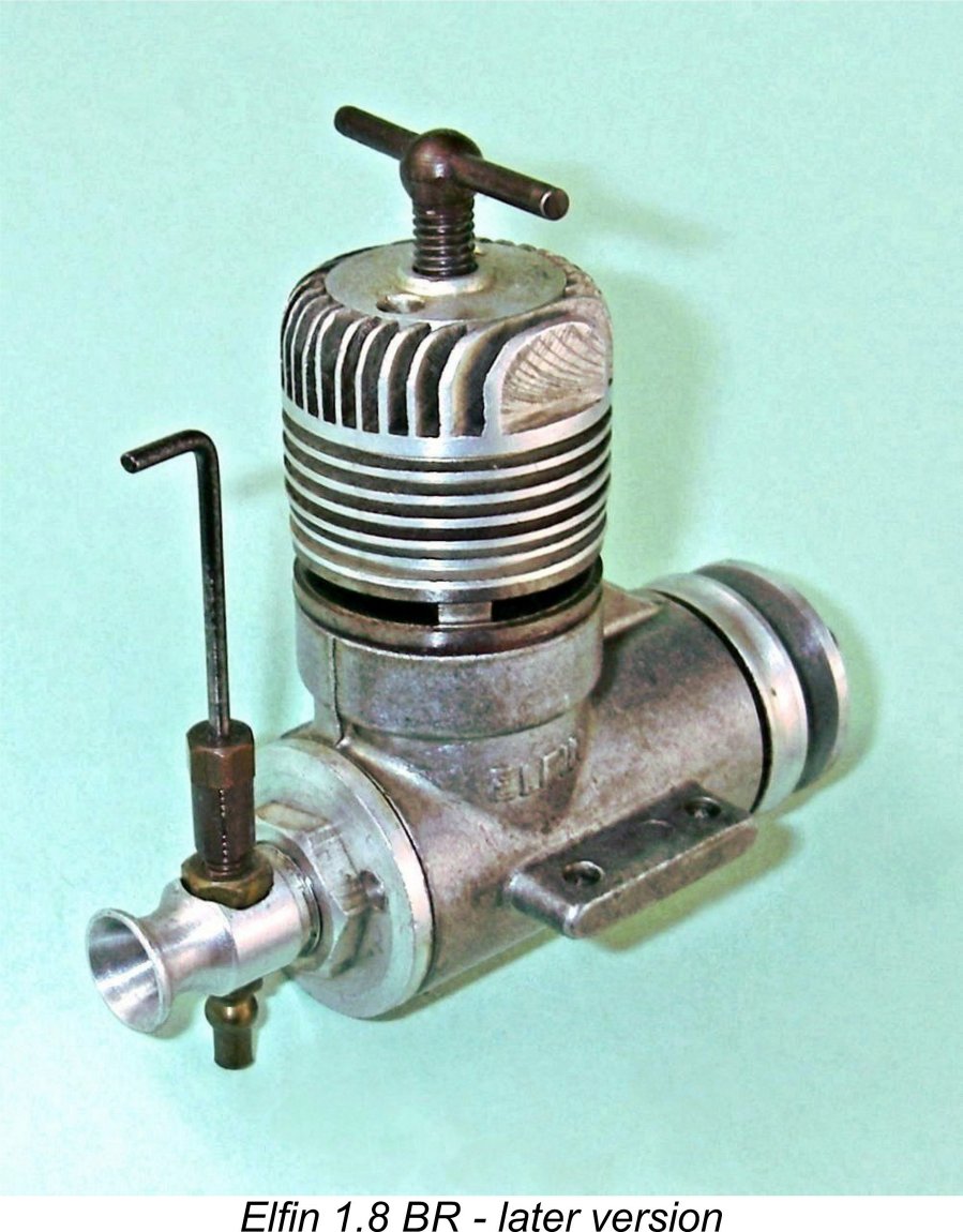
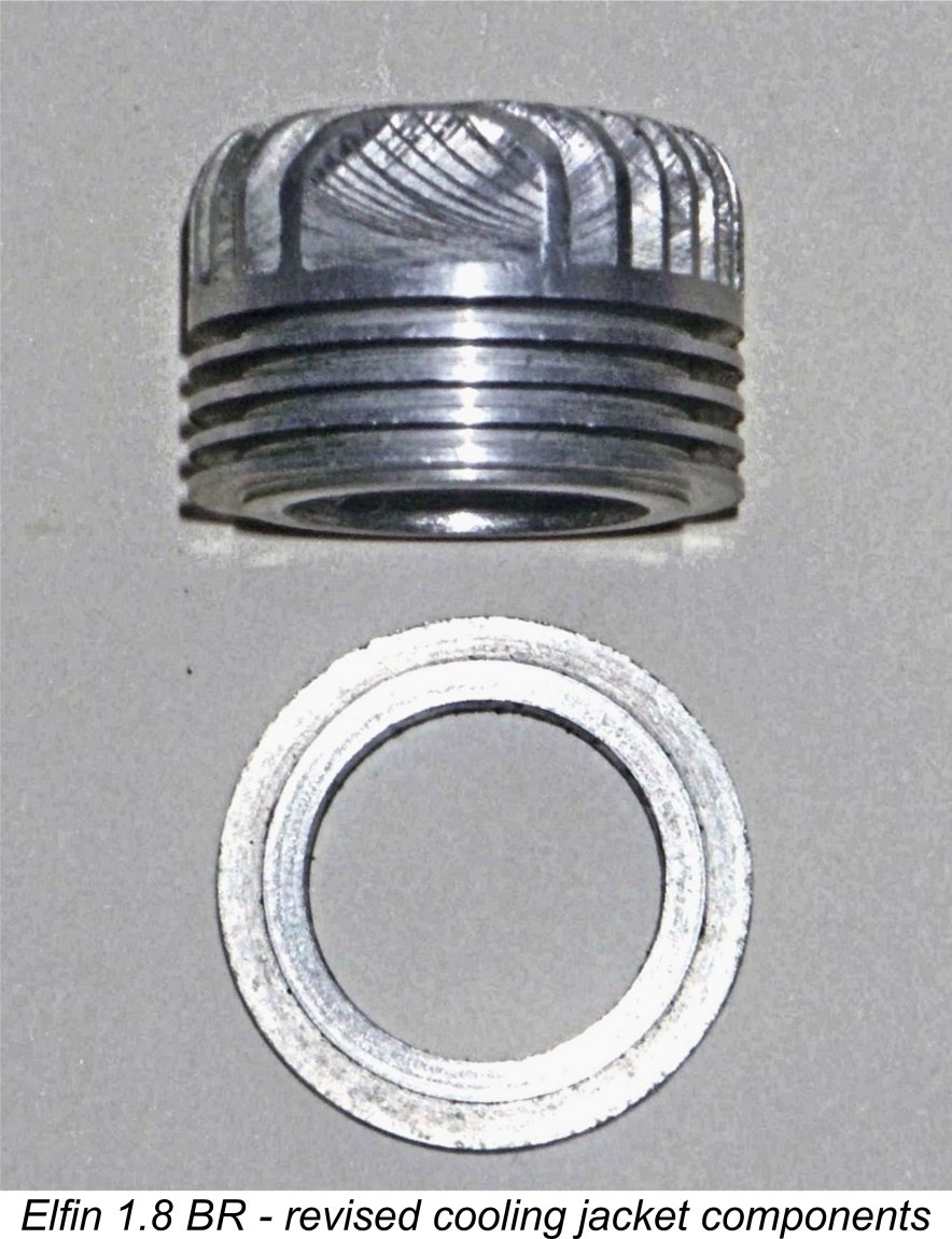
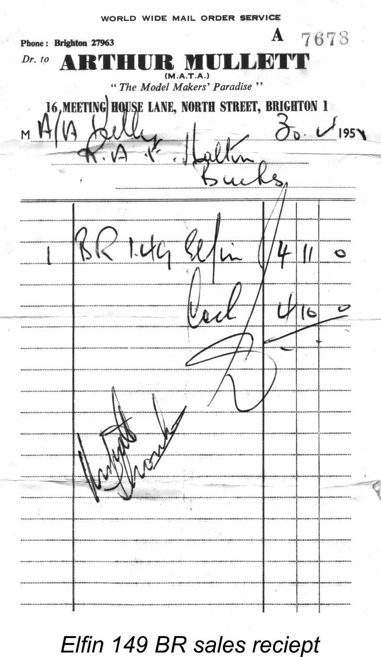
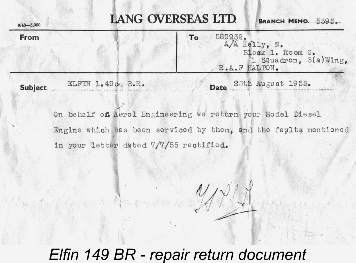 Following the delivery of the engine, most likely in mid-May 1955, it's clear that problems were either present as supplied or developed very rapidly. On July 7
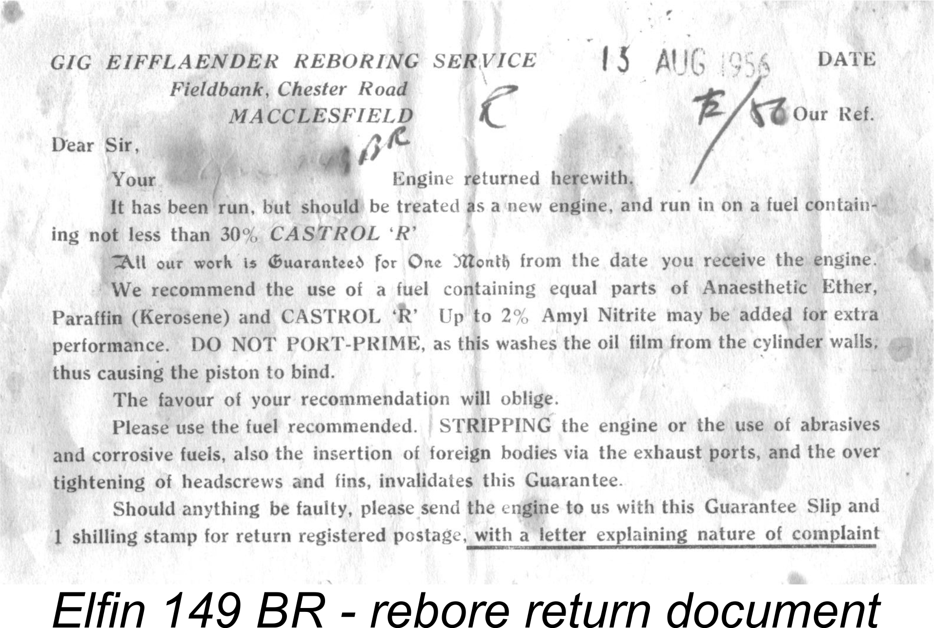 internal failure, so this was presumably a simple matter of rapid premature piston wear perhaps caused by dirt ingestion, inadequate lubricant in the fuel or possibly just a poor initial piston fit. However it came about, by mid 1956 the engine required a re-bore and was sent to Gig Eifflaender (future maker of the PAW engines) to have this work done. The re-bored engine was returned to Kelly on August 13
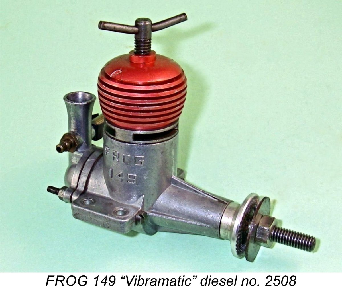
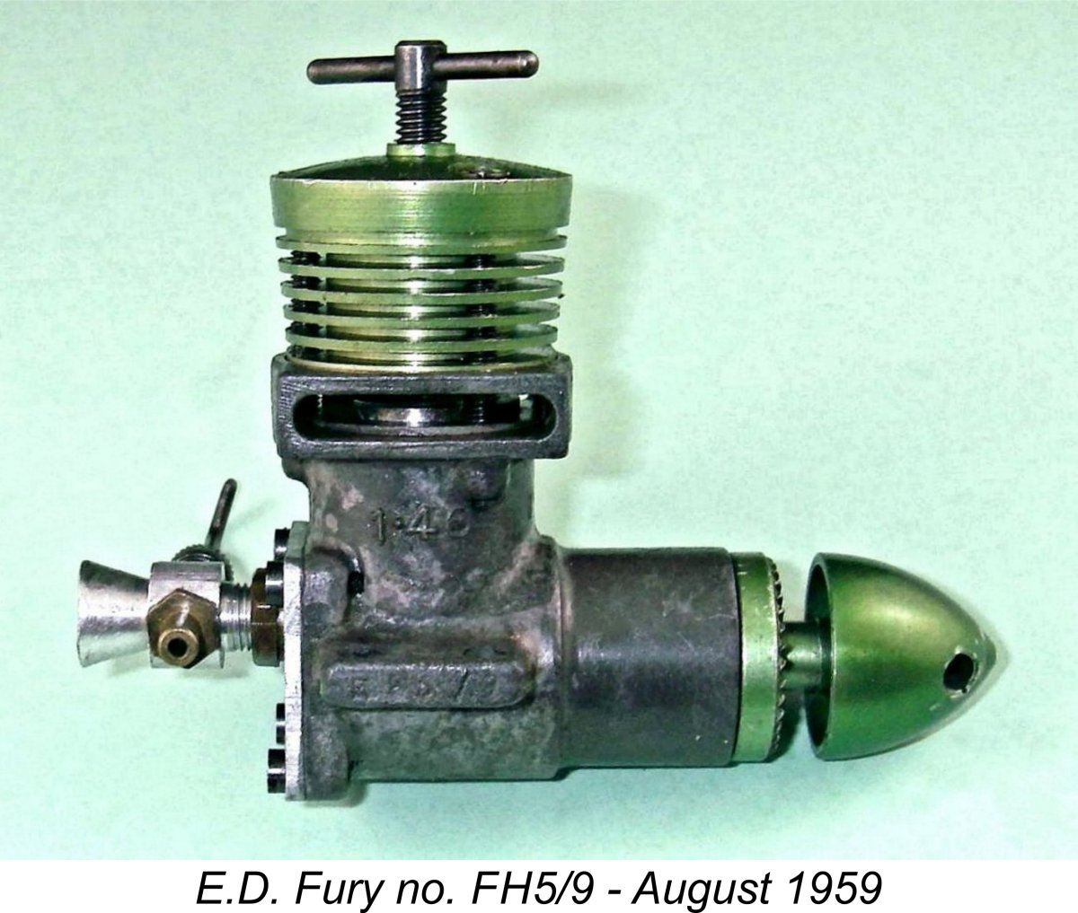 Next up was
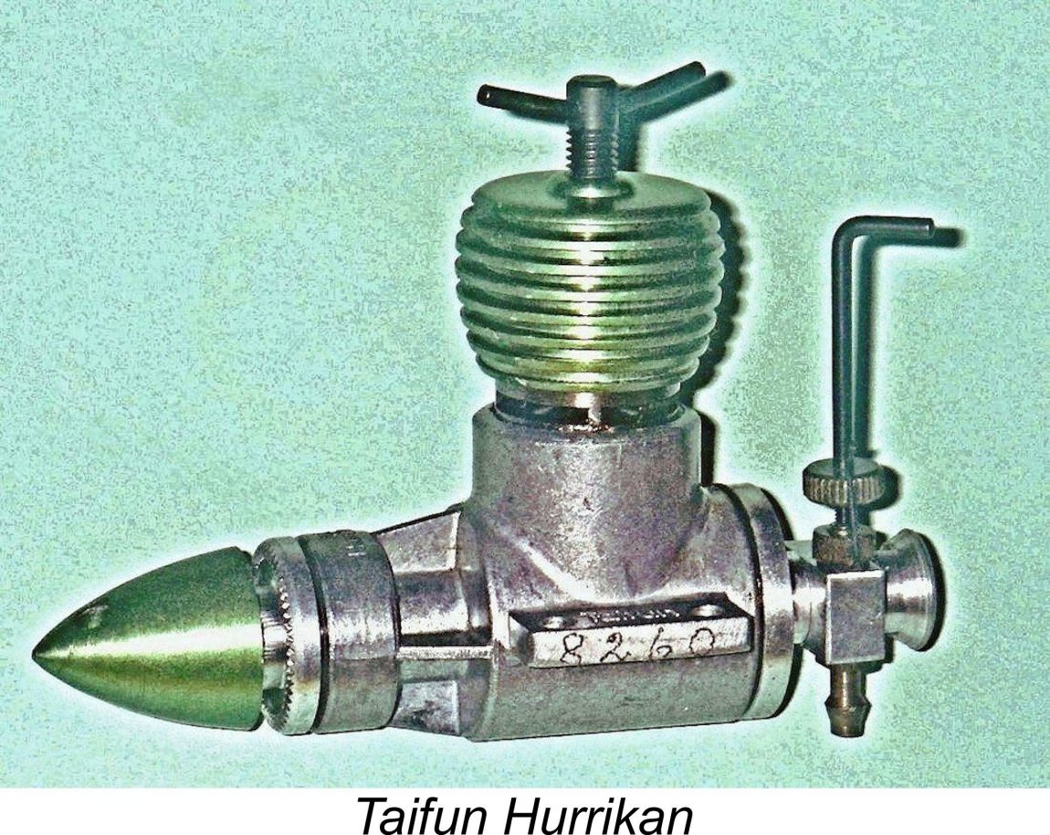
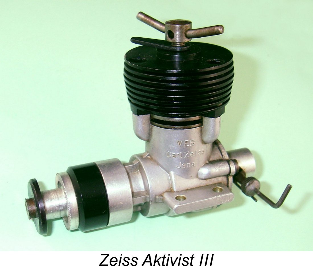 The
The 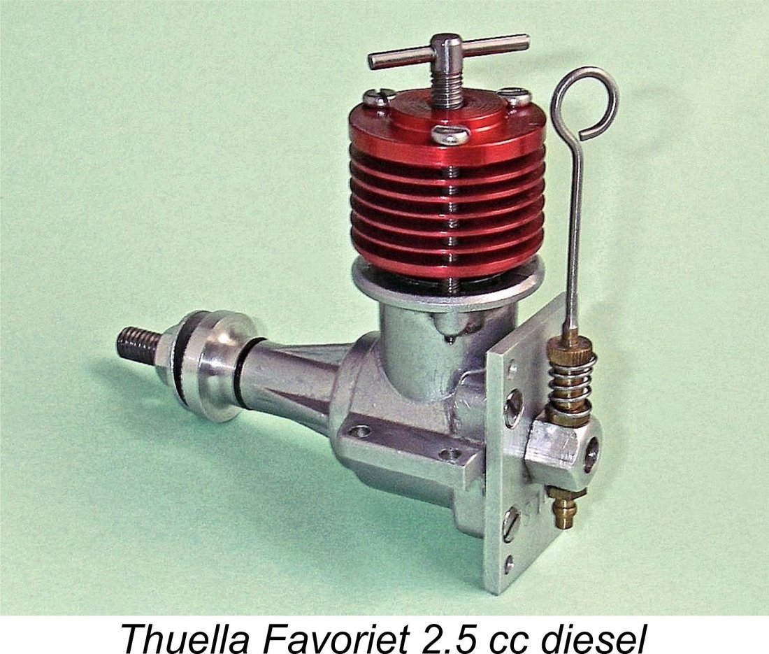
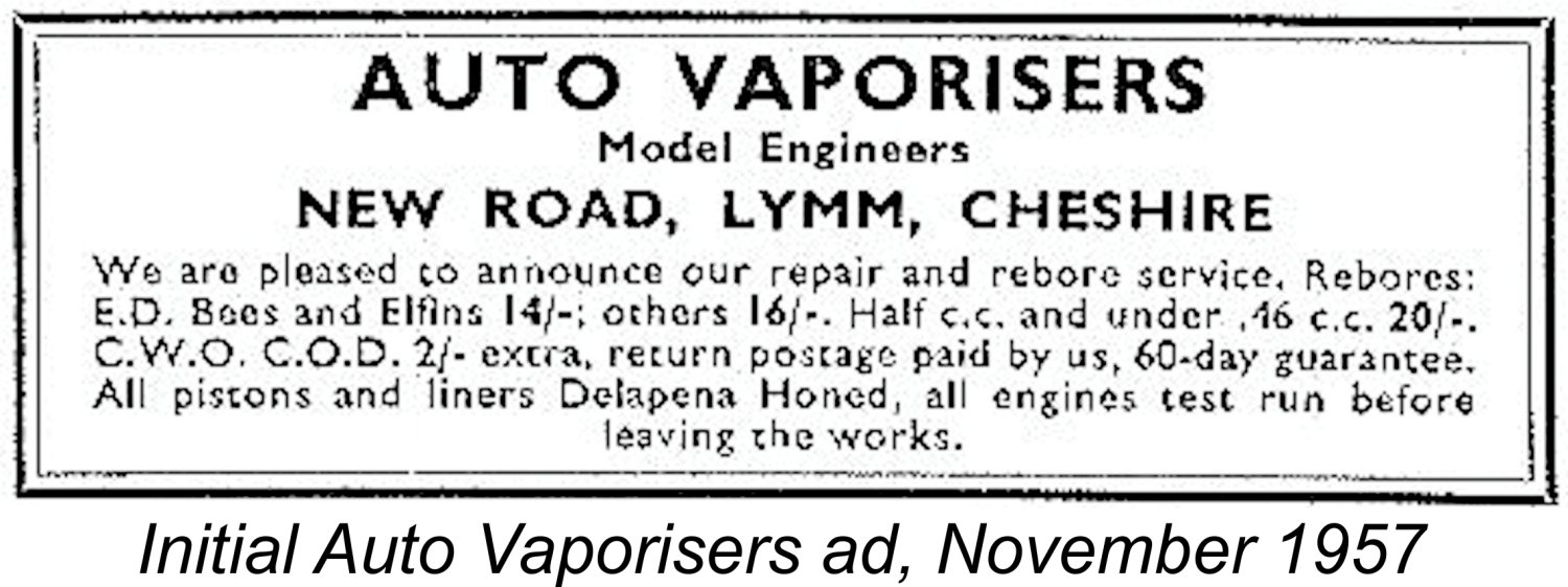 Auto-Vaporisers had first appeared on the modelling scene in November of 1957, when they were "pleased to announce" the introduction of their new engine reboring and repair service. The transfer of ownership of the Elfin marque evidently took place at around the same time, since the February 1958 “Aeromodeller” article implied that news of the transfer was then relatively recent. The article further implied that Frank Ellis retained some level of involvement under the terms of this transfer, which was said to have been accomplished "in conjunction with Mr. F. Ellis". Perhaps his continuing involvement in an advisory capacity was a condition of the sale. However, Frank made no mention of this in his recorded interview with Jim Woodside, merely stating that Aerol Engineering were still in debt when they were forced to wind up the company, hence having to sell everything to get clear.
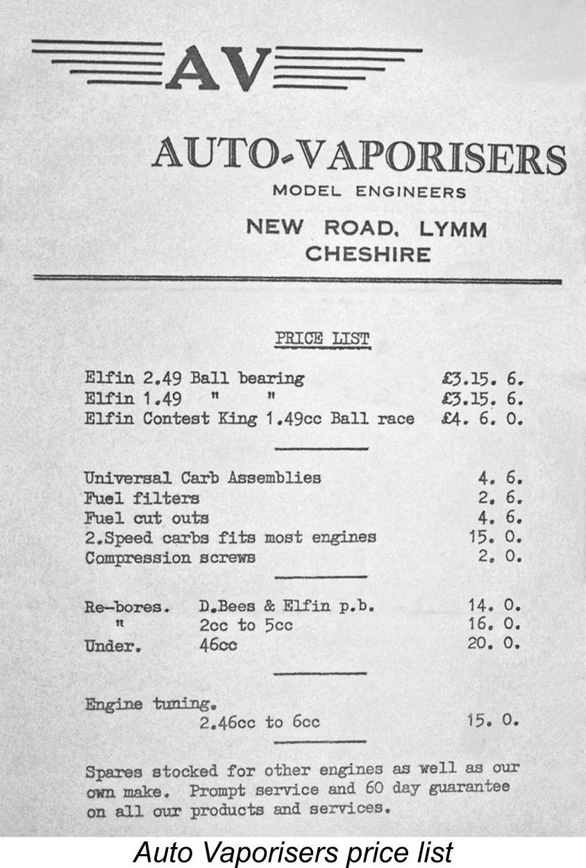 This statement suggests that production of the Elfin range had actually ceased as of 1957 pending the completion of the transfer of ownership and the elimination of the considerable backlog of servicing work which had accumulated over the preceding twelve months. It actually appears to be extremely unlikely that full-scale production of the Elfin range was ever resumed by the new owners. This view is supported by the fact that I can find no evidence that Auto-Vaporisers ever placed an advertisement for the Elfin range at any time.
 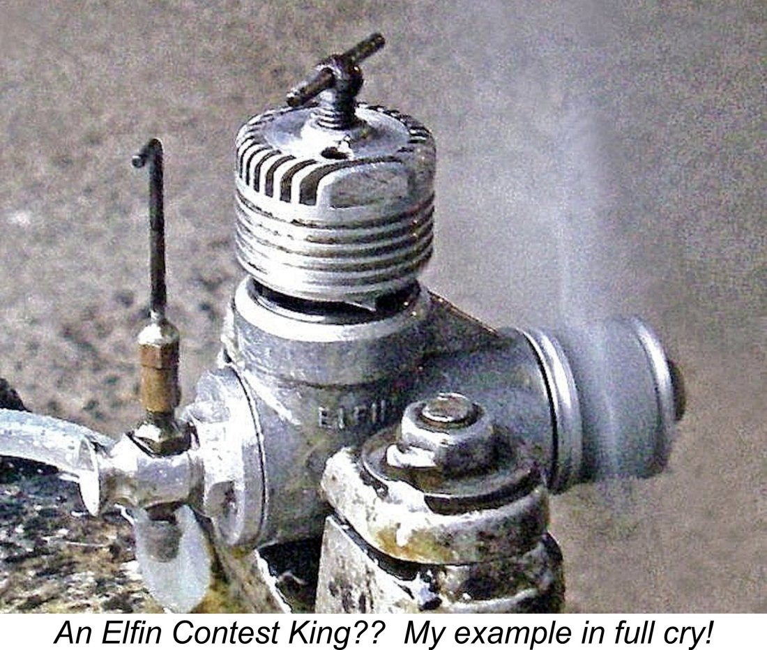 The reference to an "Elfin Contest King" 1.49 cc ball-race engine is interesting! Eric Offen had an engine identified as such in an Auto Vaporisers labelled box with papers, but it appeared to be a bog-standard Elfin 149 BR Mk. II with the four-port cylinder. Presumably these models were a high-graded batch of better-than-average examples of the second-model Elfin 149 BR. It's also possible that they were individually assembled by Auto-Vaporisers from parts acquired in the sale and were subject to an elevated level of quality control inspection and perhaps a little fine-tuning, the latter being a service which was offered by Auto-Vaporisers.
 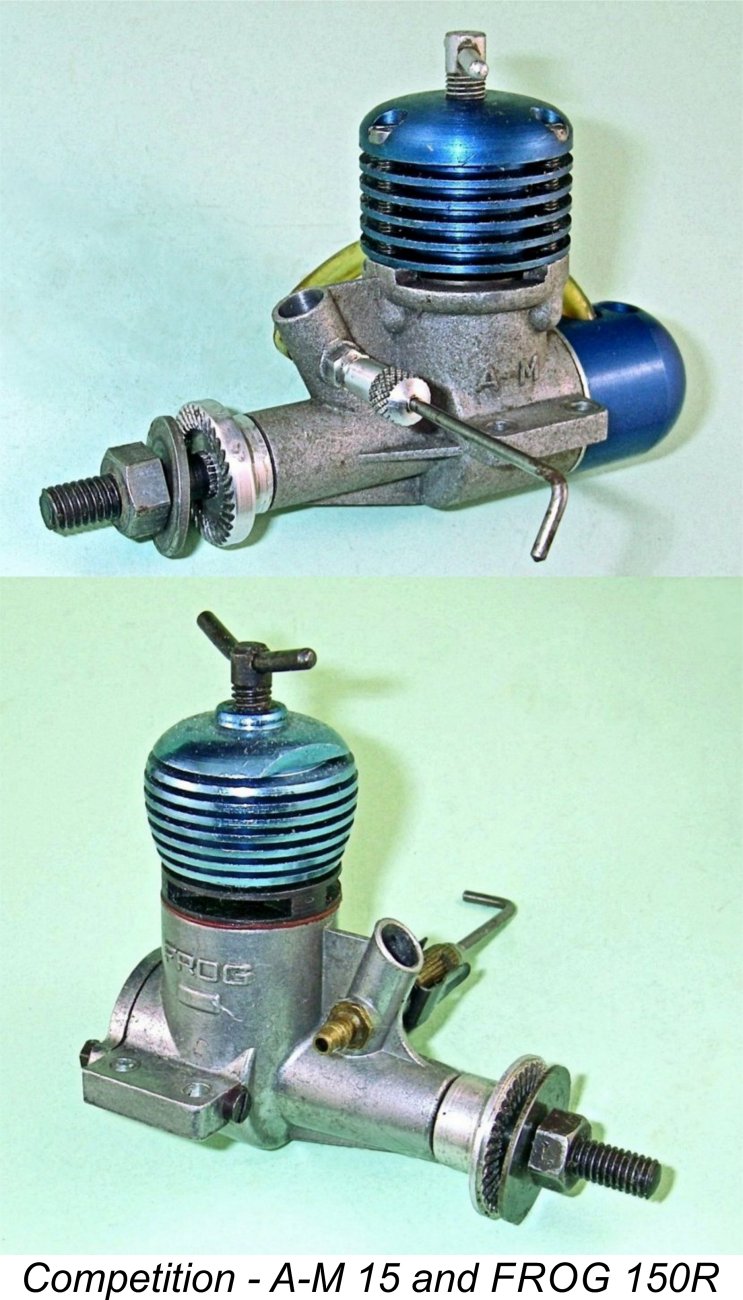 reflected in the price. As of the second half of the 1950's, the British modeller had a wide range of models to choose from in the 1.5 cc and 2.5 cc categories. Almost all of these competing models cost substantially less than their Elfin equivalents, and there was little that Aerol Engineering could do about this given the complexity of the designs.
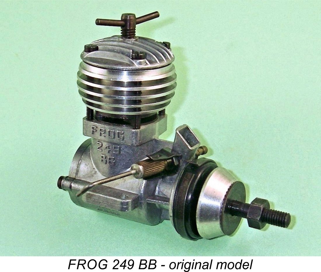 The situation was no better in the 2.5 cc category. The "consumer" market in that class was well served by such competing domestic models as the E.D. Racer, the
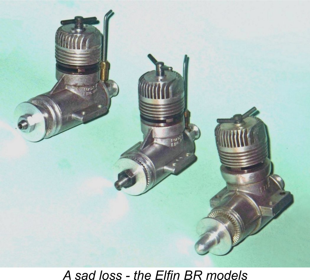
| |