
|
|
Unbekannt Deutsche Motor - der Rauch 3.2 cc Diesel
In the present case I’m able to fulfil the second and third parts of the process - the description and testing - but am unable to present any truly authoritative information about the origins of the unit under discussion. This is because my main subject here, the Rauch 3.2 cc diesel, appears to be more or less completely undocumented, even in its native Germany. Consequently, I’m actually putting this article up less to inform others than to express the very sincere hope that some kind reader(s) will be able to inform me! If you know more than I do, please get in touch!
Ronald is also one of the world’s leading authorities on German model engines. He told me that he had a number of the Rauch diesels, having evidently ended up acquiring the residue of the project at some point following its abandonment. However, even Ronald was unable to fully clarity some of the background details of this engine’s apparently short-lived manufacture, in particular leaving a few dating anomalies on the table. I’m hoping that some kind reader may know a little more and will be good enough to get in touch. All authoritative contributions will be added to this article with full acknowledgement! This was one of those purchases which I make from time to time for no better reason than the fact that I just like the look of the engine! The fact that I’d never previously so much as heard of this one added to its allure. It ended up on my workbench with me still knowing absolutely nothing about it!
Peter’s much-appreciated efforts turned up only two documentary references to the engine. One was found in a German-language book by M. Weidner of the Deutsches Museum Munich (German Museum in Munich), which is the world’s largest museum of science and technology. The other was the engine’s inclusion in a compilation booklet assembled by the late Holger Menrad. Unfortunately, the information derived from these sources was mutually inconsistent.
By contrast, the compilation by Holger Menrad cites a date of 1956 for the appearance of this engine, naming the manufacturer as being Ernst Rauch of Ackerstrasse 9, Nürnberg, Germany. He included the illustrated advertisement from Rauch which apparently appeared at an undefined date in the pages of “Mechanikus”, a German modelling magazine of the This is consistent with the information supplied by Ronald Valentine, who also cited Ernst Rauch as the manufacturer and quoted a 1956 introductory date. The large building which still exists at Ackerstrasse 9 in Nürnberg may well be the one formerly occupied in part by Rauch, although if so it has since changed uses. Ronald told me that Ernst Rauch is now long deceased.
The manufacturer's reference to this unit as a "toy engine" offers a valuable clue to the nature of its inspiration and purpose. Peter Rathke made contact with a friend of his in Nürnberg who reported that Rauch operated a small metalworking business from a garage at Ackerstrasse 9, primarily making products relating to the toy market. These included miniature sheet metal kitchen items for use in furnishing doll houses!
The engines were supplied in sturdy clearly-labelled cardboard boxes complete with printed instructions in three languages - German, Italian and French. Exports to English-speaking markets were evidently not envisioned! So far, we seem to have competing introductory dates for this engine! To confuse matters further after citing that 1956 date, Holger Menrad later injected a considerable degree of additional uncertainty regarding the dating issue in a comment on the engine which appeared in issue no. 108 for December 1993 of Tim Dannels’ invaluable “Engine Collectors' Journal” (ECJ). This was in response to a submission from ECJ reader Jerry Campbell, who sent in a few images of an example in his possession with a request for help in identifying it. Jerry’s submission appeared in issue no. 107 of ECJ for October 1993.
The Rauch stationary model was evidently one of these, seemingly dating it to the early post-WW2 “stationary engine” era despite the references to 1956. Holger stated that like others of its type it was not successful, partially because of the inherent limits to its potential application and also due to the prevailing economic conditions in Germany, which greatly constrained peoples’ discretionary spending. In addition, Ronald Valentine commented quite frankly that some aspects of the unit’s construction left something to be desired, an assessment which later examination has proved to be correct (see below). Both sources agreed that very few examples were made. Holger classified the engine as an extremely rare collector’s item.
The rather “primitive” design of the Rauch is completely inconsistent with an introductory date of 1956. With its very restrictive cylinder porting (see below), the engine is far more logically placed among the pioneering diesel designs of the early post-WW2 period when model diesel designers were still very much feeling their way forward. By 1956 standards, the design of the Rauch is a complete anachronism. There seems to be absolutely no economic logic in the concept of Ernst Rauch commencing production of this engine in either stationary or aero forms in 1956 - model engine design in Germany had moved far ahead of such technology. Weidner’s suggested date of 1951 makes far more sense, and even that date seems pretty late ……………
The other question relates to the originality of my aero model. When first consulted, Peter Rathke stated that he had never seen an aero version of the engine, nor had he heard of the existence of such a model. He thought that my example might be a stripped-down example of the stationary model with a few aero components fitted. In my view that is almost certainly true, but the question remains - who did the conversion? Just how “official” was it? Ronald Valentine stated that Ernst Rauch was a personal friend, from whom he had received the engine which I now own. This being the case, a very logical explanation presents itself immediately. It seems likely that the engine was indeed produced originally in stationary form but that Rauch created a few examples for himself and a select few friends which were re-configured as aero models. Ronald may well have been one of those friends. If so, the number of aero models could probably be counted on the fingers of one hand! A a result of his further inquiries on my behalf, Peter Rathke was able to confirm that my aero example is not unique - he learned that a similar unit was in the possession of a Swiss collector as of May 2021. It's thus clear that at least a few examples of this conversion were in fact produced. Further support for this notion comes from an old eBay listing for which I found a surviving on-line artefact in the form of some text. The images had long vanished, but the text specifically referred to the engine which was evidently being sold as a Rauch Aero model having a displacement of 3.42 cc. It's clear that a handful of such engines do exist, although there seems to be some ambiguity regarding the claimed displacement.
In this case, one of the associated images had survived, as seen at the left. The engine appeared to be missing its fuel needle. The exaggeratedly elongated tank was very different from that used with the “standard” stationary model, perhaps being an owner creation. The cylinder head appeared to be the standard transverse fin component which had been rotated 120 degrees in a counter-clockwise direction viewed from above. Overall, the engine looked like an example which had been converted to model boat use. Returning now to the question of the originality of the aero variant of this engine, I'm certain that my newly-acquired example of the Rauch is a purpose-built aero model, although I very much doubt that it started out in that form. Look at the head fins – the ones on the stationary engine are transverse, while those on my engine are axially aligned. Moreover, the transverse-finned head of the stationary model appears to be a casting, while that featured on my aero variant is very nicely machined from high-quality OK, how to make sense of this mix of often contradictory information? My valued friend Peter Valicek of the Netherlands has come up with the best reading that I’ve yet encountered. His view is that the engine was indeed introduced in the late '40's or early ‘50’s as a stationary engine during the "no-fly" era in post-WW2 Germany. It was probably originally designed and manufactured by Rauch, but may well have been marketed by a different company, as suggested by Weidner. However, it didn’t sell, for the reasons stated by Holger Menrad. The residual stationary engines remained in storage until 1956, when Rauch resumed his efforts to market them, perhaps hoping that the vastly improved economic conditions in Germany by that time would result in more sales attention. If so, he would have been very disappointed - the effort apparently met with as little success as before. The engines may have been kept on offer until 1962, as Ronald suggests, but it seems highly unlikely that Rauch manufactured any new examples during this period. He would have had no economic incentive to do so. Finally recognizing that the effort was going nowhere, Rauch or a successor converted a small handful of examples to aero models for a few friends (like Ronald) strictly as curios, subsequently allowing the project to die. The residue of the project appears to have ended up at some point in the hands of Ronald Valentine.
As a final comment, I'll just remind my readers that Rauch appears to have been primarily a maker of sheet metal items for the toy industry. The baseplate, engine mounts and tank of the stationary Rauch offering are entirely consistent with this line of production, while the actual engine itself is not - it required both foundry and machining skills. It seems possible that someone other than Ernst Rauch made the engine, while Rauch created the stand and assembled the final product. We'll probably never know whether or not this is true, but it can't be dismissed as a possibility. Having presented such information as I’ve been able to discover, I’ll leave it to you, dear reader, to make up your own mind! For myself, I’m inclined to believe that this engine dates from the late 1940's or very early 1950’s as its design architecture suggests; that it was produced in small numbers strictly as a stationary model; and that a very few aero variants were created by Ernst Rauch (or a successor) for himself and a handful of friends prior to the residue of the project ending up with Ronald Valentine. OK, time to move onto firmer ground! Let’s have a closer look at this evidently very rare engine! Description
I'm fairly certain that all of these engines were built to the above repeatedly checked bore and stroke dimensions. I believe that the various different figures quoted by others as reported above are the result of improper measurements, incorrect assumptions or honest mis-readings of figures recorded by others. Given the very small numbers in which this engine was evidently produced as well as its "toy engine" status, there's absolutely no logic in the concept of differing displacements being offered. The Rauch is based upon a pair of aluminium alloy gravity castings which appear to have been produced using permanent molds. In a European context, this implies an expectation that the engine would be produced in sizeable numbers, an expectation which was evidently not fulfilled.
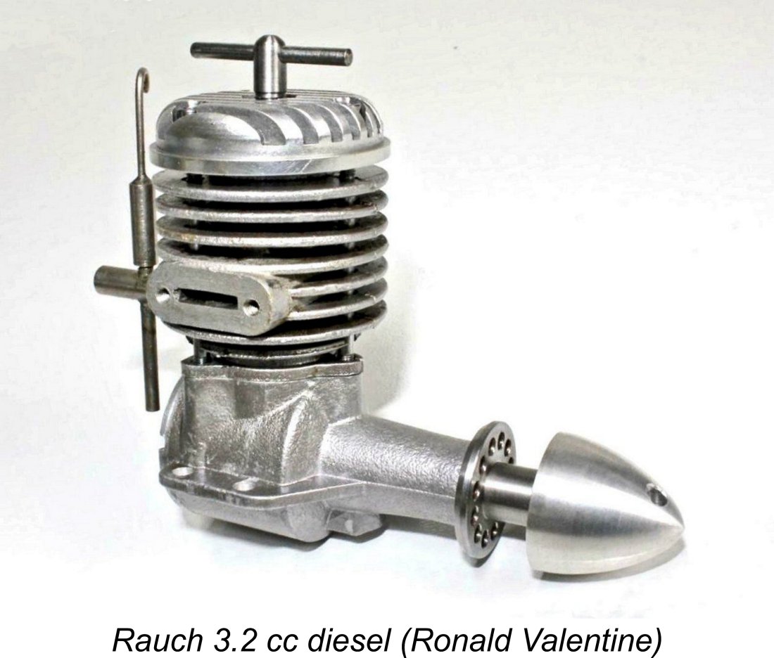
The cylinder barrel is closed off at the top by a deeply-finned cylinder head. As fitted to the stationary variants of the engine, this appears to have been another casting with transverse fins. By contrast, the aero model has a fully-machined head evidently created from bar stock. As previously noted, this was necessitated by the need to orient the head cooling fins in a fore-and-aft direction for aero service. This orientation could not be achieved using the standard cast transverse-finned head because of the three-stud hold-down arrangement The aperture provided in the upper casting for the exhaust is unusually small. This is one of the features which is strongly suggestive of an early date. Provision is made in the form of two tapped holes in the ends of the exhaust stack for the fitting of an exhaust conduit or muffler. This can be seen very clearly in the accompanying image. The sheet metal exhaust collector directs the exhaust discharge downwards. This appears to be missing on many existing examples. The top of the main crankcase features a triangular location flange which matches that at the base of the upper cylinder. This is drilled and tapped at three locations to accommodate the very long cylinder hold- The main crankcase also incorporates the integrally-cast main bearing housing and the beam mounting lugs. The latter features are notably skinny by normal model aircraft standards, likely because the stationary applications for which the engine was originally intended would not expose it to crash damage. In fact, the inadequacy of these lugs for aircraft service strongly supports the idea that such applications were never envisaged when the engine was designed. The cylinder liner is made of hardened steel. It appears to be shrunk into the surrounding cylinder barrel - I was unable to shift it by "fair" means. The bore is very nicely finished but appears to lack any of the taper which is highly desirable in a model diesel engine.
This is a real issue with this design, because the transfer flutes actually stop well short of the lower edge of the exhaust, providing a woefully inadequate transfer period of around 65 degrees. I say “around” because all four transfer ports don’t open quite simultaneously - the figure given is an average. The exhaust period of some 130 degrees is a far more rational figure which clearly implies that a longer transfer period would have been both possible and highly desirable. The induction period of around 70 degrees is also a little marginal, albeit somewhat closer to reality for such a low-speed engine as this one appears to be. The piston is an extremely heavy component made from cast iron. A great deal of reciprocating weight could have been machined out of the interior, but wasn’t. The piston is an excellent The conrod is of the familiar “dog bone” pattern which results in relatively short bearing lengths at both ends. It is a hardened steel forging, which seems likely to give rise to fairly rapid bearing wear, particularly at the small end - steel-on-steel is a poor wearing combination. In all honesty, the dimensions of its column appear to be rather marginal for service in a diesel engine of this displacement. That said, the component appears to be very well-made, with excellent bearing fits at both ends. The main downside is the reciprocating weight - the illustrated complete piston and rod assembly weighs all of 21 gm, almost 8% of the total weight of the aero version of the engine!
At the front of this example, a very nicely-machined steel prop driver is featured. This seems to be mounted on a shallow-angle self-locking tapered section of the main journal - I couldn’t remove it by “fair” means to check. Unusually, the prop driver face is drilled rather than being knurled to provide some measure of rotational security for the prop. The front of the crankshaft is internally threaded to accommodate a separate externally threaded stud. The prop is secured by a streamlined aluminium alloy spinner nut which mounts on this stud.
To characterise the fuel supply arrangements as rudimentary actually flatters them somewhat! The intake is a simple thin-walled steel tube which seems to be pressed or shrunk into the spigot at the rear of the upper cylinder casting - I didn't disturb it to check. The spraybar is another simple steel tube which is soldered in position in the intake tract. That said, a number of images exist of engines having more conventional spraybars which are secured by nuts. It seems that both styles were used - factory images exist showing both arrangements. The aero variant retains the very long fuel pickup which was originally associated with the tank mounted on the stationary model's stand. The needle itself has a thimble which is not provided with any kind of split to provide tension. Instead, an internal coil spring is used inside the thimble, rather like the needle valves used on many of the E.D. models of the 1950's.
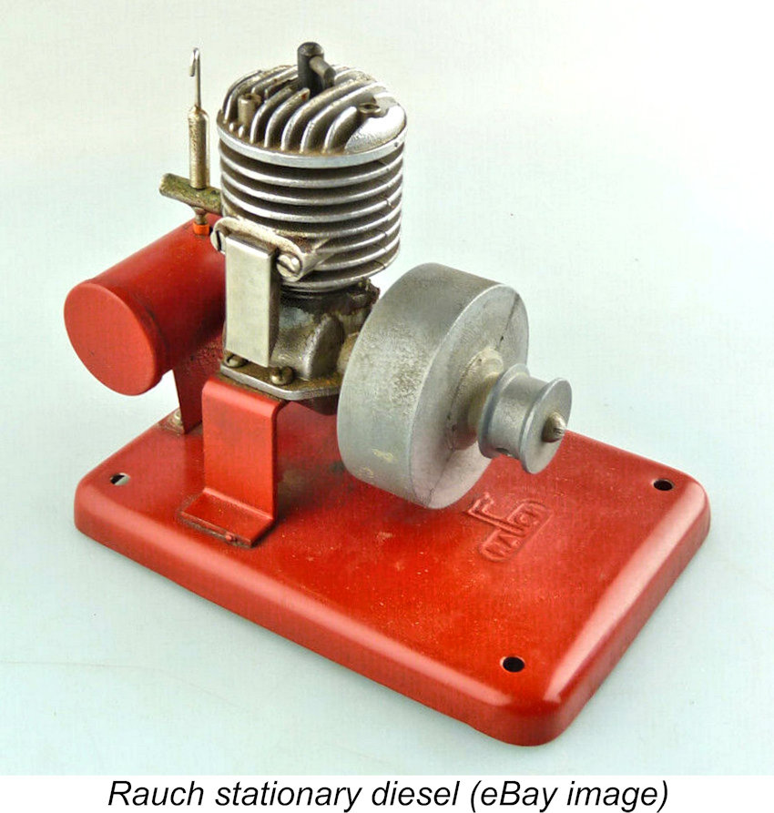
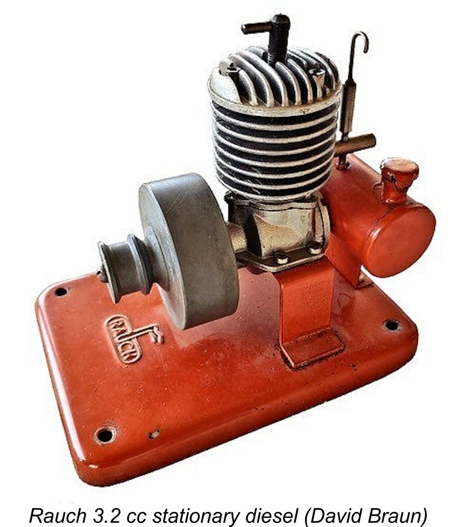
Being an “aero” variant, my engine is unaccompanied by a stand. When Jerry Campbell sent in the details of his previously-illustrated stationary example which appeared in issue no. 107 of ECJ for September 1993, he commented that the base, mounts and tank were all painted a nice bright red colour. The base of the stand had the Rauch name embossed in relief onto its surface. The attached later image by David Braun from ECJ issue no. 257 confirms these details. The above description should have clarified a number of serious design shortcomings in this engine which are completely consistent with Ronald Valentine’s somewhat unflattering assessment quoted earlier. In the context of the quality-oriented German model engine manufacturing industry of the 1950's, those same shortcomings argue eloquently against a date as late as 1956.
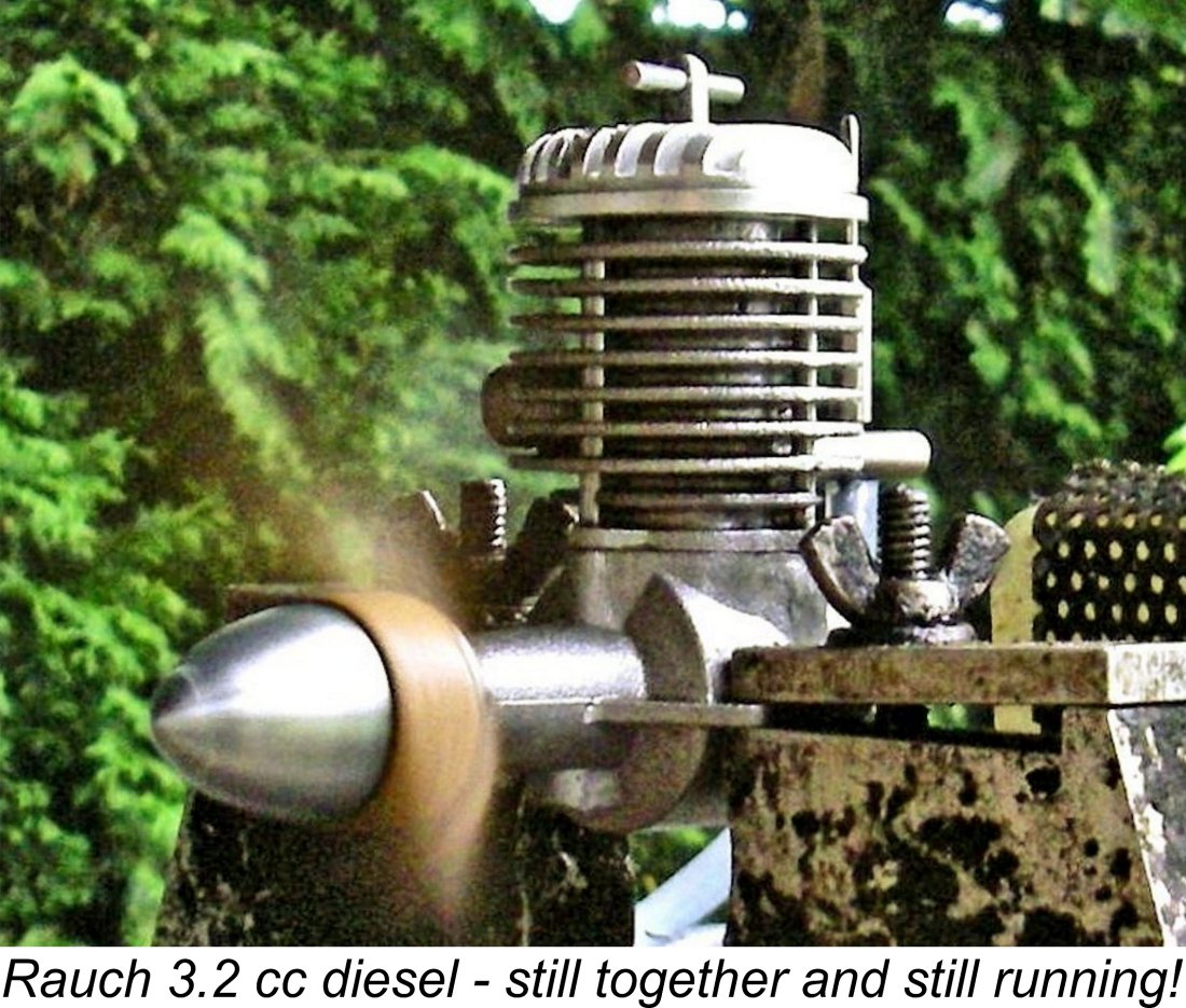
My overall comment is that I’ve seen far better-made and certainly better-designed engines from contemporary German manufacturers. By 1956, model engine design and manufacture in Germany had both moved far ahead of the standards embodied in this engine. The whole style and feel of this unit place it in the early post-WW2 period when designers were still feeling their way. The designer of this particular engine undoubtedly had a long way to go to gain a full understanding of many of the basic requirements of model diesel design. As stated earlier, I'm quite certain that my "aero" example of the Rauch 3.2 cc diesel started out as a stationary model like all the others, having been converted either by Rauch himself or by a successor more or less as a curio. The great advantage of this conversion having been undertaken is that it greatly facilitates efforts to actually run the engine. That inevitably brings us to the question to which you’ve all been waiting for an answer - how does it run? I’m as curious as you, so let’s find out ……… but cautiously! The Rauch 3.2 cc Diesel on Test In all honesty, I wasn’t expecting too much in the way of performance from this engine - the very restrictive cylinder porting, extremely heavy piston and unbalanced crankshaft all implied a relatively low operating speed with constrained torque development. The engine’s general design led me to believe that it might develop reasonable torque at the lower speeds but would not go very far up the rpm scale - indeed, its clear vibration potential would make this appear highly undesirable. I also anticipated some trouble establishing optimal needle valve settings. Moreover, the engine’s previously-enumerated structural deficiencies did not inspire confidence in its ability to stand up to much running. The undersized crankpin and wrist pin in particular presented concerns in this regard. In testing it at all, I honestly felt that I was taking a bit of a risk. Still, nothing ventured, nothing gained - I felt that I really had to see if the thing did actually run! If it broke, it broke ………….. Even so, I decided beforehand that I was going to limit both the amount of running and the maximum test speed to which I would subject the engine. The very heavy piston and unbalanced crankweb presaged a high level of vibration, while the very skimpy mounting lugs seemed pretty much guaranteed to fail due to vibration-induced fatigue at a relatively early stage. In addition, the crankpin and gudgeon pin both appeared highly susceptible to early failure. Accordingly, I planned to confine my ambitions to briefly experiencing the engine’s handling and running characteristics without worrying too much about establishing its peak power output with any precision.
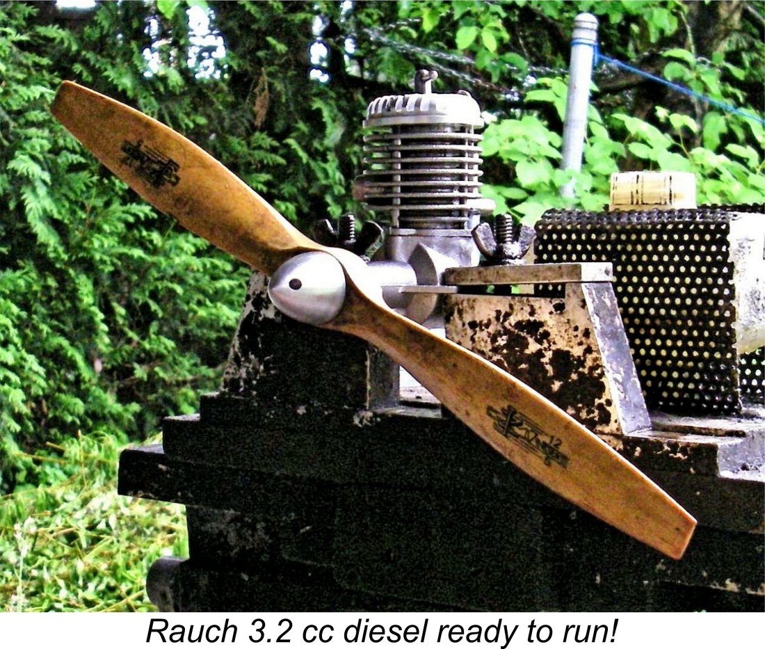
Before mounting the engine in the test stand, I conducted some experiments with a fuel bulb to establish what seemed by ear to be a reasonable needle setting for starting. Given the engine's primitive needle valve configuration, I was expecting a bit of a struggle with the fuel mixture, so anything that I could do to adjust the engine in advance would definitely be helpful. Set up in the stand with its 12x5 wood prop fitted, the Rauch felt pretty good when flicked over, with excellent compression. I started with the compression set at a very low level, figuring that it would be kinder to the seeemingly rather skimpy working components to approach the correct starting compression setting from below. My replacement contra piston proved to be perfectly fitted, making compression adjustments both smooth and secure. I gave the engine two choked flicks, noting the rate at which fuel was drawn along the fuel line as I did so. Since this looked OK to my experienced eye, I administered a small exhaust prime and started flicking in earnest, going for a start. The procedure was to flick four or five times at a stretch. If there was no response, the compression was increased a little, after which the flicking was resumed. Once in a while I administered another small prime to replace fuel shot out of the exhaust.
Correcting this condition immediately brought me face to face with the limitations of that flat-ended needle! As anticipated, the engine was unbelievably sensitive to the needle setting - a fraction of a turn took it from somewhat too rich to a lean cut-out. Getting to a really good setting was very much a matter of luck, aided and abetted by trial and error. If I was planning to use the engine to power a model (which I'm not!), I would definitely add a taper to the metering end of the needle. As things stood, I left well alone in the interests of maintaining originality. For any future bench running, I would use a remote needle valve installed in the fuel line. One factor that mollified my somewhat uncharitable view of the engine at this point was perhaps its greatest virtue - easy starting. Once I had the starting settings more or less sorted, a couple of choked flicks followed by one or two starting flicks were all that were ever required. Then came the challenge of getting that pesky needle set for best performance. That process never ceased to be a total pain in the neck! A fair number of restarts were necessary, making me very appreciative of the engine's easy starting. After finally managing to luck into a reasonable needle setting for the 12x5 test prop, the uncharitable views returned in force! I was brought face to face with another major issue - there simply wasn't much power being developed. The Rauch ran smoothly enough but turned the 12x5 Zinger wood prop at a lowly 3,600 rpm - around 0.036 BHP. Oh dear!! Hoping for better things at higher speeds, I switched to a 10x7 Top Flite Power Point wood prop, but could only get the engine up to 4,400 rpm (c. 0.043 BHP) on that prop. A further change to an 11x4 Zinger wood prop only allowed the engine to reach 4,900 rpm (c. 0.046 BHP).
For what it's worth, the power curve implied by this minimal amount of testing is reproduced here at the left. Given the small number of actual data points, this curve is a rough estimate at best, but it does give an accurate impression of this engine's rather astonishing lack of power. The average .049 cuin. glow-plug motor of the mid 1950's could develop more power, albeit at far higher speeds.
Mind you, it's probably that lack of performance that allows the engine to survive at all in operation with that 3 mm gudgeon pin, 5 mm crankpin, skimpy rod bearings and excessive reciprocating weight. At these speeds, ignition timing will be pretty retarded, minimizing compression ignition stresses upon the working components. Moreover, reciprocating stress reversals will likely remain within manageable limits despite the extremely heavy reciprocating components. If I was serious about using this engine to power a model (which I'm most definitely not!), I would begin by machining a whole bunch of weight out of the piston interior - reciprocating weight is a performance-killer. I would bore out the piston bosses to 6 mm and fit a larger gudgeon pin. This would of course require the making of a new light alloy rod, which would further reduce reciprocating weight. I would remove some material from the crankpin side of the crankweb to create a little counterbalance. I would enlarge the bypass channels to the extent possible, also raising the tops of the two channels opposite the exhaust to create some overlap. The two ports on the exhaust side can't be raised much, hence being reduced to the status of boost ports under this scenario. Finally, I would modify the needle to create some taper at the metering end, thus permitting the achievement of more precise fuel mixture settings. I have no doubt at all that these modifications would improve both performance and consistency very considerably. The skinny 5 mm crankpin would remain, but perhaps the reduction of reciprocating weight would allow the engine to rev somewhat higher without over-stressing that component. All of this having been said, I have no intention of destroying the engine's originality as it stands. It is what it is, and the record of the design's shortcomings as embodied in this example needs to be preserved. Summary and Conclusion The above comments should have highlighted the readily-apparent unsuitability of the Rauch 3.2 cc diesel for model aircraft service. These findings have convinced me completely that it was never intended for such applications. Quite apart from its excessive weight and bulk for the minimal power developed, it embodied a number of design shortcomings which would almost certainly have caused its early failure in aero service. In particular, the first crash would probably have fractured those very flimsy mounting lugs.
The engine's minimal performance strongly implies that it is best seen as an I/C expression of the "table-top" stationary model engine genre, of which numerous examples were manufactured as steam engines and Stirling Cycle hot air units both in Germany and elsewhere. Mind you, Mum would very likely have been extremely upset to find one of these things running on the kitchen table! My very accommodating Mum put up with my steam engines and hot air engines, but I'm sure that she'd have drawn the line with even a low-performing diesel unit! It actually seems possible that the very low performance of this engine was intentionally designed into it given its intended stationary operation. Even running unloaded with a flywheel, it's unlikely that much higher speeds than those that I achieved with a prop would have been reached, It appears that the undoubted existence of a very few aero models is due to a small handful of such variants being created either by Rauch himself or by a successor purely out of interest, probably in the late 1950’s or early 1960’s. Such variants almost certainly didn’t feature at all in the original design and manufacture of this engine. Moreover, the very few aero examples that were created were clearly not seriously expected to be used in actual service in the field - rather, they were created as curios or keepsakes. It must be said that both the design and construction of this engine leave a good deal to be desired - Ronald Valentine’s assessment was spot-on. However, fairness to Ernst Rauch requires us to view this assessment in context. Since the Rauch 3.2 cc diesel was never intended to be used as a hobby engine, judging its merits in that context is quite unfair. As a table-top engine for "recreational running", it was probably perfectly adequate. However you look at it, the Rauch 3.2 cc diesel is a fascinating example of a more-or-less forgotten aspect of model diesel design - the stationary "table-top" engine. As such, for all its shortcomings it remains a fascinating collectible. I’m certainly glad to have experienced my own example - at least I've proved that it runs! ________________________________ Article © Adrian C. Duncan, Coquitlam, British Columbia, Canada First published July 2023
|
 Dies ist ein Artikel mit einem Unterschied! In fact, its subject is an engine with a difference! Normally I write articles about engines which I’ve researched very thoroughly, thus being able to share a wealth of authoritative information with those interested. It’s my usual practise to present the background to the engine’s development and production; to describe the engine in detail; and then to summarize my own present-day test analysis of the engine’s performance.
 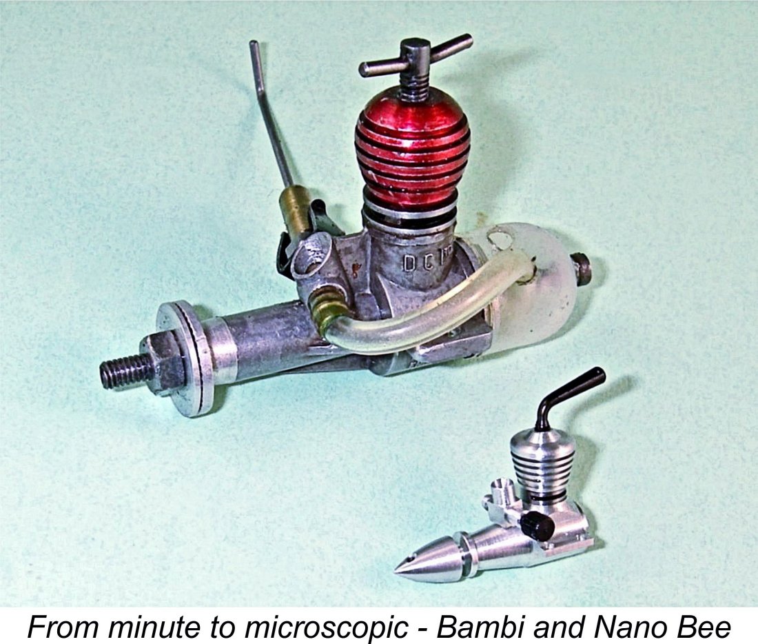 I acquired this engine from the collection of noted German-American model engine guru Ronald Valentine, who is best known for his amazing sub-miniature engines. Perhaps Ronald’s most noteworthy achievement was the creation of his truly remarkable Nano Bee diesel of only 0.006 cc displacement (and no, I did not skip a decimal point!). As you can see, this one makes an Allbon Bambi look like a large engine!
 Whenever I’m stumped on a German engine, one of the first people with whom I consult is always my valued German friend Peter Rathke. Peter was kind enough to check for possible German sources of information. However, he came up largely empty, while some of what he did uncover was contradictory.
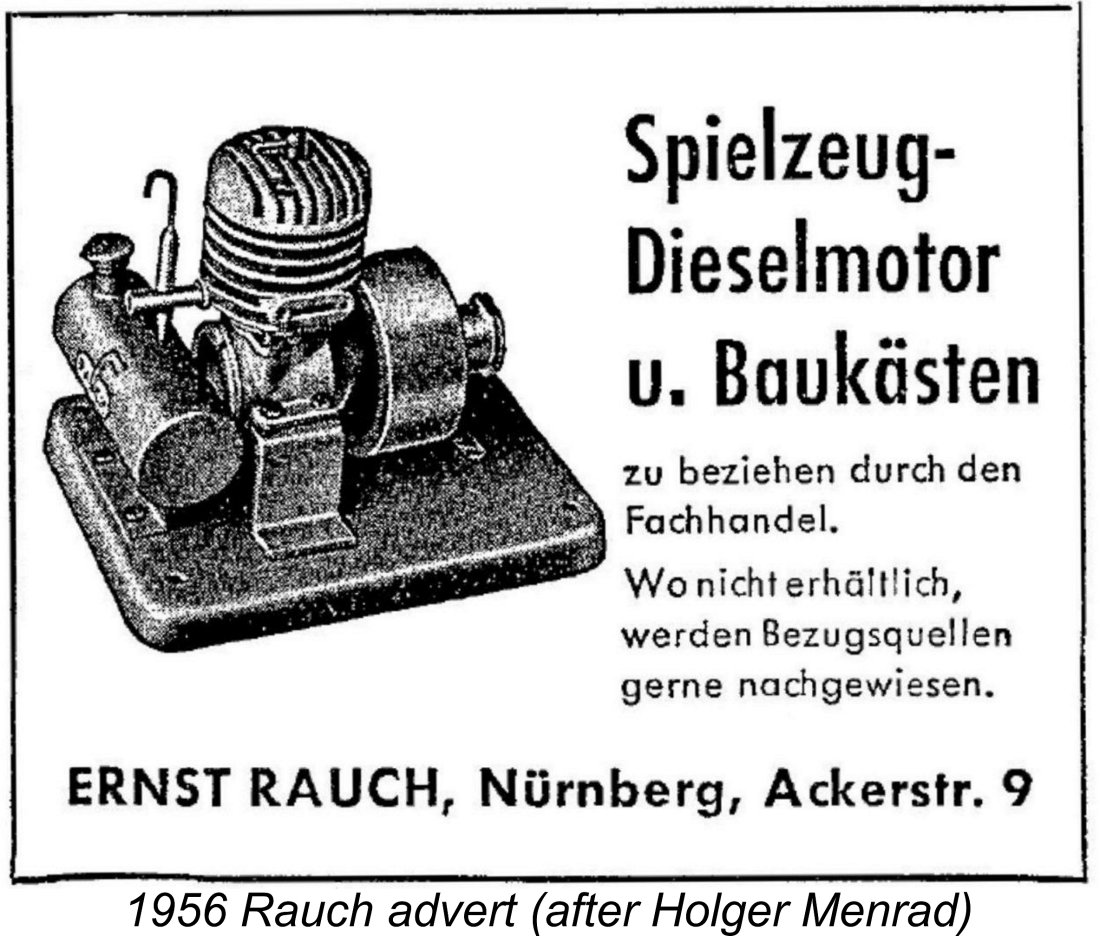 The first source reportedly claimed that this engine was developed and manufactured in 1951 by a Berlin company called "Der Spielkasten" (The Toy Box) as a stationary engine supposedly having a 3.7 cc displacement. I must say that this name looks far more like that of a toyshop than a model engine manufacturer! I’m not convinced …………although the date sounds about right. Perhaps they were the marketing agents for the engine as opposed to the manufacturers.
 period. The name “Rauch” means “smoke” in German, and you have to appreciate the Rauch trade mark with its burning cigarette (or spouting smokestack)!
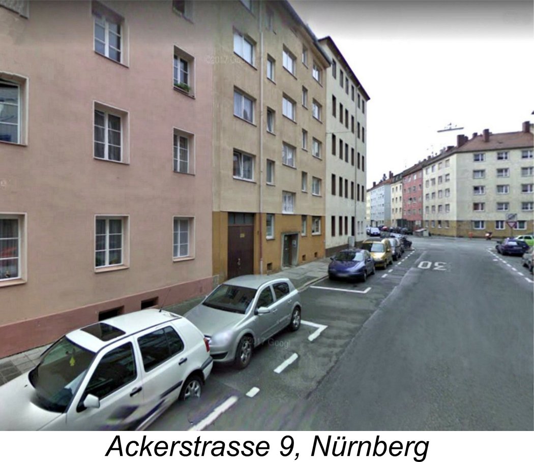 The text of Rauch’s previously-illustrated magazine advertisement translates to: “Toy diesel engine and construction kits are available from specialist dealers. Where not available, sources of supply can be identified”. This implies that the engine was marketed as illustrated in stationary form along with a range of models in kit form which it could be used to power.
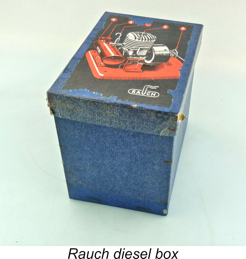 According to Peter's friend, the “Spielzeug Dieselmotor” (Toy Diesel Engine, as it was called by its manufacturer) was also aimed at the “toy” market, never being intended for use in serious hobby applications. Such a target market would make complete sense of the engine being marketed by "Der Spielkasten" (The Toy Box) as claimed by Weidner. It is probably the fact that it was never marketed as a "hobby" powerplant that has resulted in the engine being completely ignored hitherto by the modelling media.
 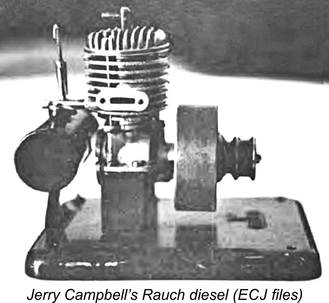 In his December 1993 response, Holger noted that during the early post-WW2 period, aeromodelling in Germany was officially banned by the occupying powers, since it was seen as a possible element of a pre-military education (as indeed it was in Russia and elsewhere behind the Iron Curtain). Accordingly, the manufacture of engines which could be used to power model aircraft was likewise forbidden. In consequence, a number of stationary (non-flying) and model boat engines were the first model powerplants to appear on the post-war German market.
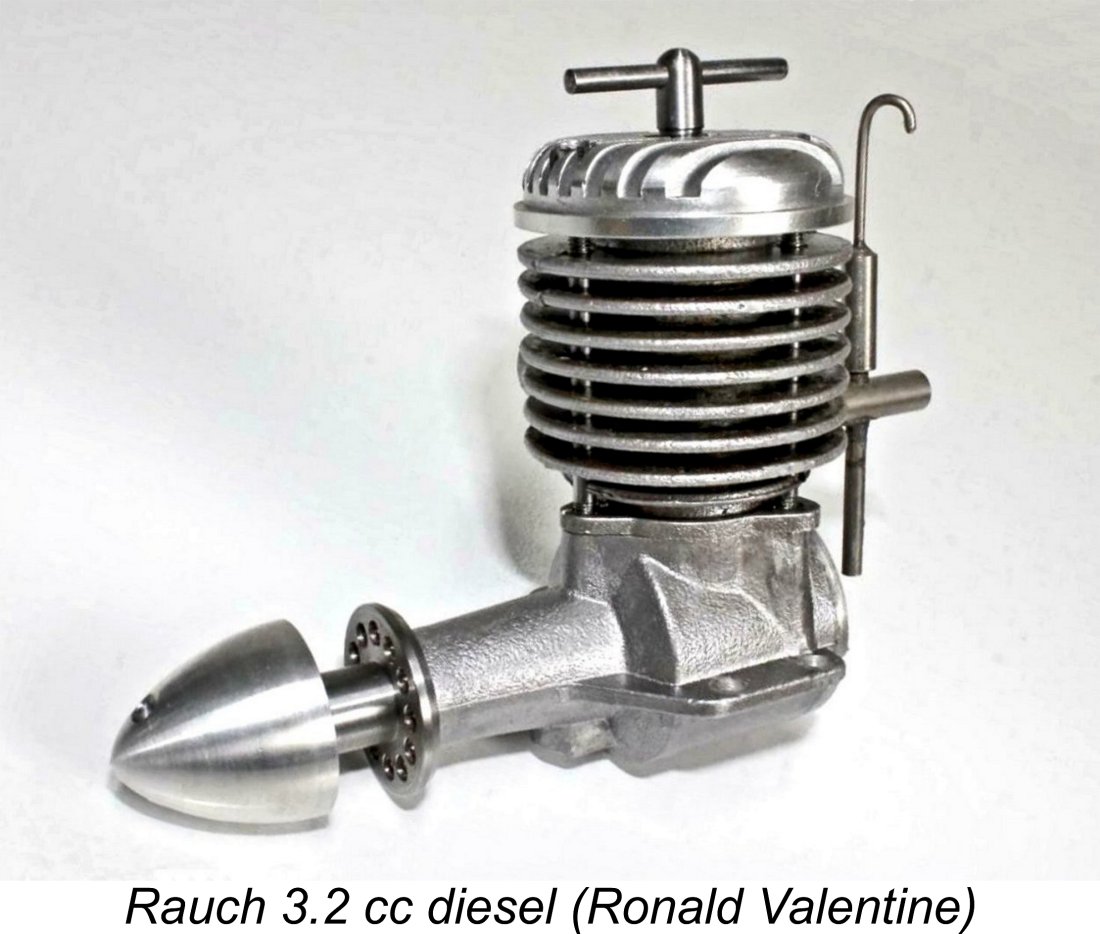 Holger’s comment flies very much in the face of his own suggestion that production of this engine commenced in 1956 - the early post-WW2 circumstances which he described actually seem to make a far earlier date appear highly probable. By 1956, Germany had been fully re-admitted into the fold of aeromodelling nations and had achieved a prominent position in the international model engine manufacturing field, with such well-known brands as Webra and Taifun leading the way.
 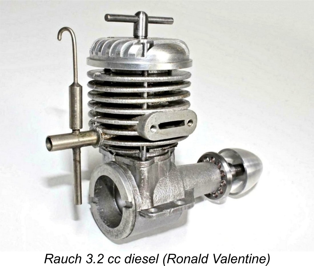 Ronald Valentine himself threw a further spanner in the works of this argument by stating that the Rauch diesel was produced by Ernst Rauch in small numbers between 1956 and 1962. With the very greatest respect to Ronald, I have to admit that this claim raises far more questions than it answers! First, a six-year production period implies an ongoing demand, however modest. Where would that demand have come from? Moreover, during those six years a reasonable number of engines should have been produced, even if monthly production was very small. This being the case, where are they all now?!?
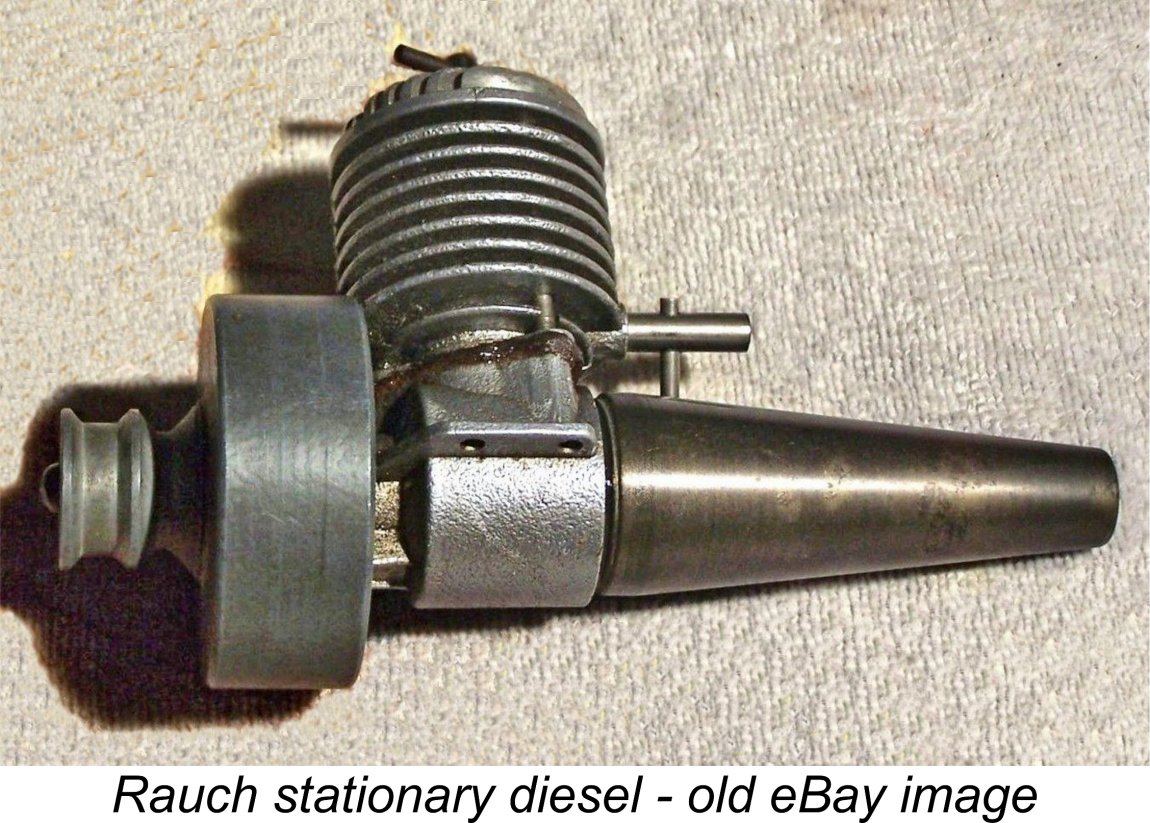 Speaking of displacement, the ambiguity doesn’t stop there - there’s also the 3.7 cc displacement figure quoted by Weidner. Could the 7 have been a mis-read 2?!? To confuse matters still further, I also found an artefact of yet another old eBay listing of a Rauch stationary engine for which the seller specifically claimed bore and stroke measurements of 16 mm and 14 mm respectively for a displacement of 2.81 cc. Weight was cited as being 650 gm including tank and flywheel but minus the stand, which was not with the engine.
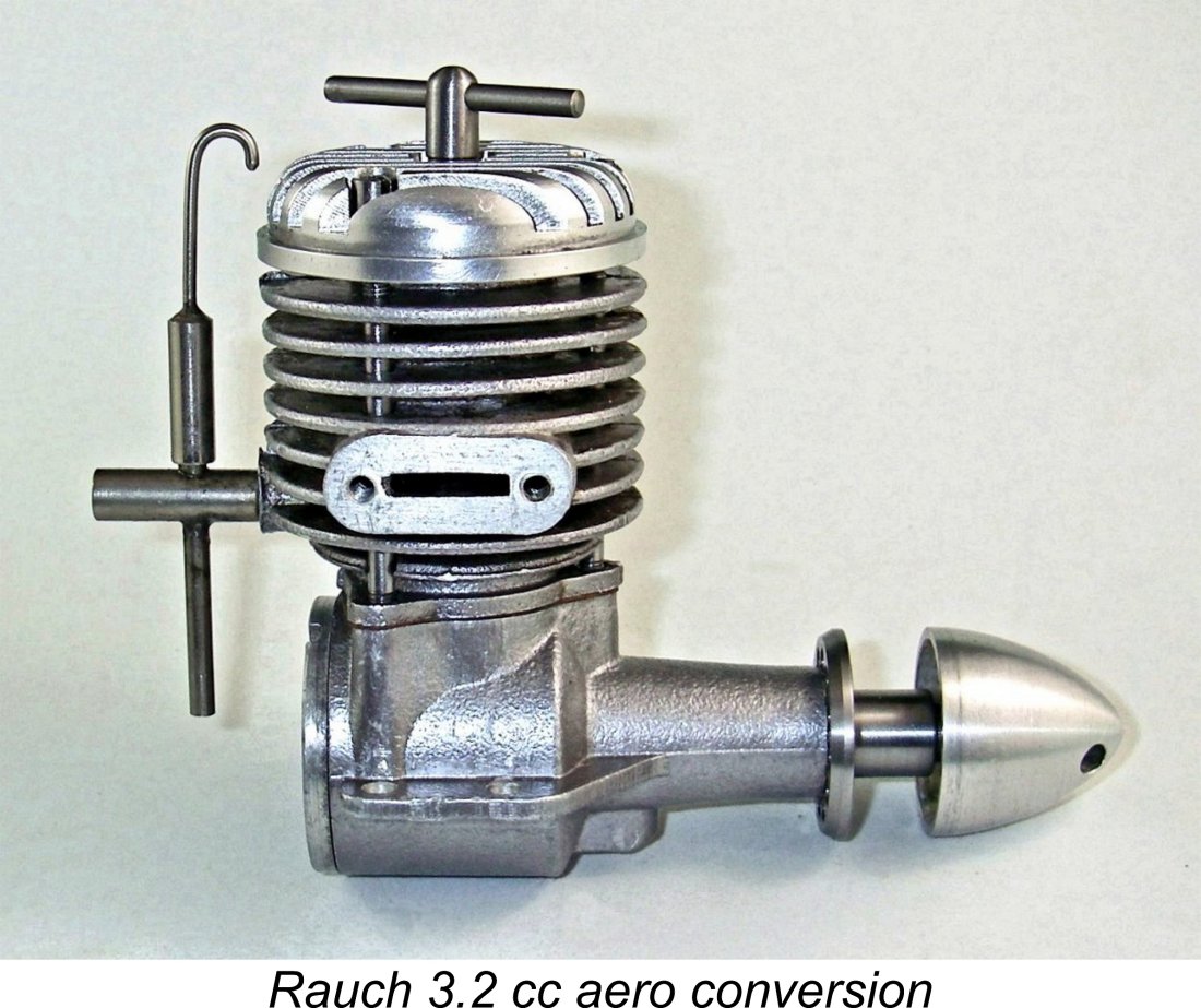
 I like Peter’s reading because it explains everything - the dating anomalies, the possibility of a different company being involved originally and the dates provided by Ronald. Of course, it may not be correct - has anyone out there got a better interpretation? If so, let’s hear it!
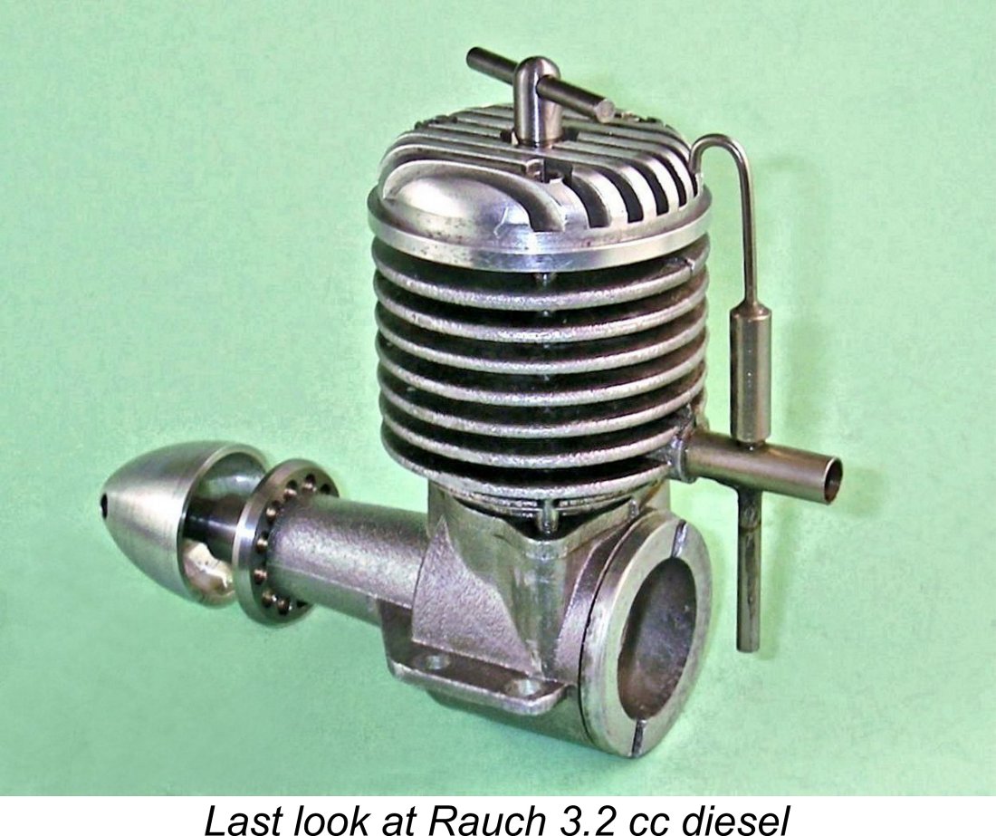
 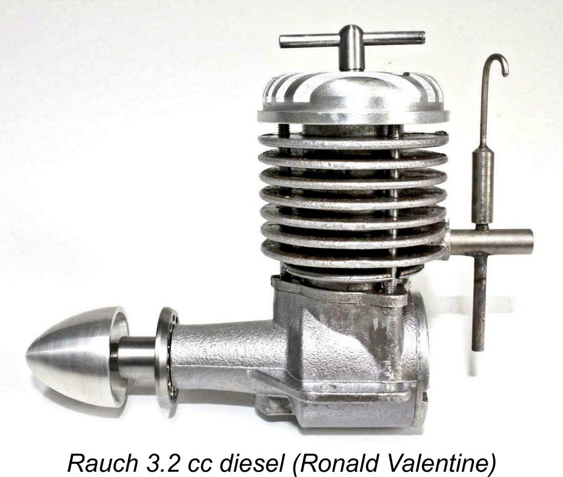 As the accompanying images will show, the Rauch diesel was a basically conventional side-port design of the early post-WW2 era. It was mainly distinguished by its greater than average bulk along with its unusual and rather striking styling. The illustrated aero-converted example has measured bore and stroke dimensions of 16 mm and 16 mm for a displacement of 3.22 cc (0.196 cuin.). It weighs a ponderous 272 gm (9.6 ounces) as illustrated in its aero form minus tank and flywheel.
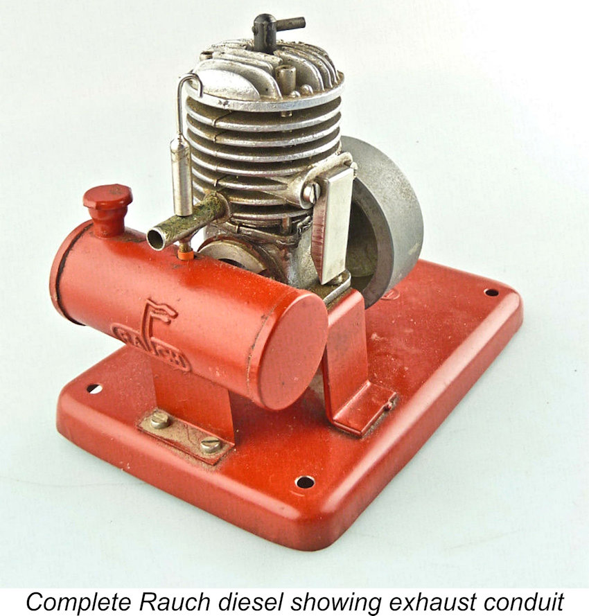 The massive upper casting comprises the cylinder barrel with integrally-cast cooling fins, stubby exhaust stack, induction spigot and triangular location flange at the base. The massive dimensions and very deep finning suggest an effort to promote adequate cooling i
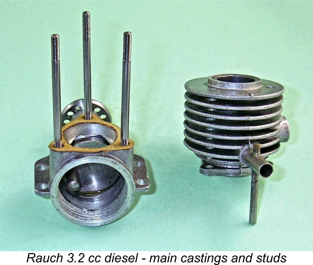
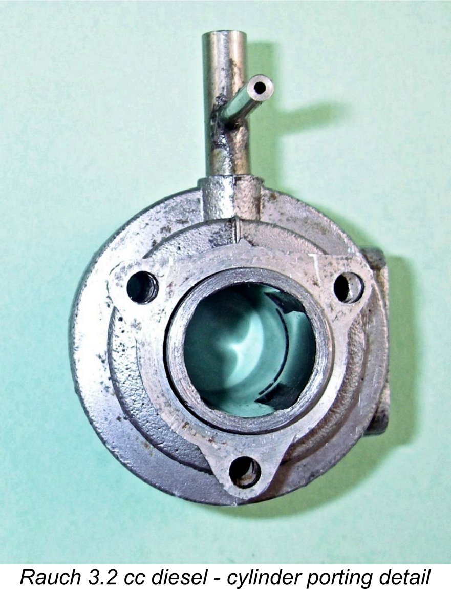 The cylinder porting is rudimentary in the extreme. The induction port is a simple round hole of modest diameter through the rear of the cylinder wall. The bypass/transfer arrangements appear to be totally inadequate for an engine of this displacement. They consist of four very small internally-formed flutes uniformly spaced around the bore which perform both bypass and transfer functions. The exhaust port consists of a single wide rectangular opening set above two of the bypass flutes. Because those two flutes align with the outer portions of the exhaust port, no overlap can be provided.
 The well-made crankshaft is a one-piece hardened steel component having an unbalanced plain disc crankweb. Coupled with the excessive reciprocating weight, this lack of counterbalance creates an expectation that vibration levels will be highly problematic. Crankpin diameter is only 5 mm, a dimension which once again appears somewhat marginal for effective long-term service in this engine.
 The rear of the crankcase is sealed in the conventional manner by a screw-in backplate. The thread is unusually coarse as well as being a fairly loose fit, leading me to suspect that keeping the backplate tight might be a bit of a problem. A fibre gasket is used to create a seal.
 Having then recently tested a replica of a 1946
 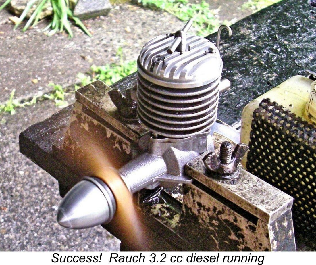 I soon reached a point at which my very experienced flicking finger told me that I should be getting close. At that point, I was rewarded with a few half-hearted firing strokes. Now at last I knew where I was, and a further small compression increase had the engine running in short order. I'd guessed about right on the needle for starting, although it was definitely on the rich side for running.
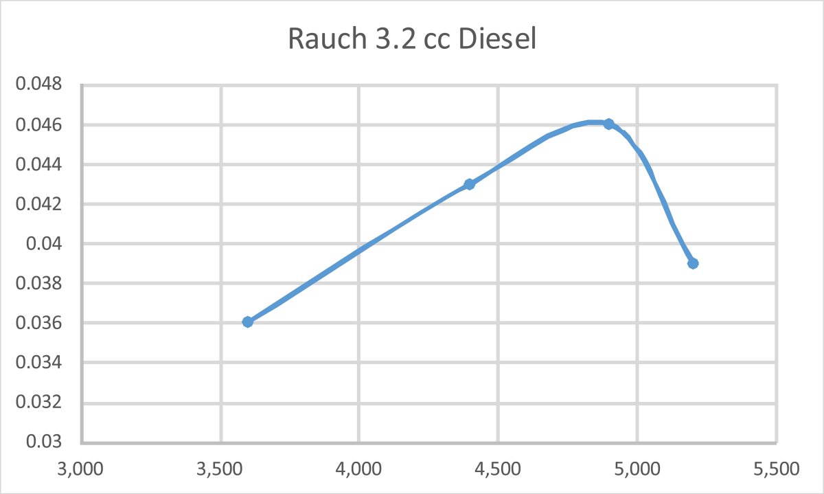
 For that reason, I’m convinced that this model belongs to the “stationary engine” period of the late 1940’s and early 1950’s rather than the middle and later years of the 1950’s, as suggested by some. The very rudimentary and excessively restrictive porting is very much consistent with an early date, as are the extremely heavy reciprocating components. Efforts to market existing stocks of the engine may have resumed during the latter half of the 1950's, but I very much doubt that any manufacturing was taking place by that time.
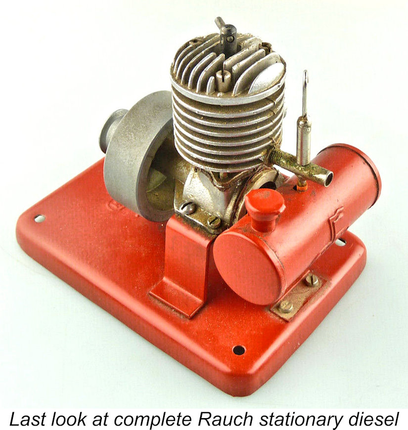
| |