
|
|
Arden Masterpieces - the Mighty Atom Engines
Few individuals have had a greater influence on model engine history than Thomas Ray Arden (who always went by his second name). A full biography of Ray Arden by Charlie Reich may be found on the AMA website. Another most informative article about Ray and his work may be found here on the Internet Craftsmanship Museum website. Finally, there's an excellent Ray Arden tribute page which may still be found on the late Ron Chernich's "Model Engine News" (MEN) web-site. There's no reason whatsoever for me to repeat any of this material here - I’ll just mention the relevant highlights. Born in 1890 (d. 1965), Ray built his first rubber-powered model airplane in 1901, following this up by constructing his first model aero engine in 1908 at the age of 18 years. This spark ignition unit weighed around 16 ounces and powered a six-foot wingspan model biplane of Ray’s own design and construction. A 14-ounce twin-cylinder model followed in 1910.
Ray went on to become a prolific inventor, creating a multitude of innovative designs which went far beyond the confines of model aviation. By the 1930’s he was focusing for the most part upon new toys, establishing his own company called Ultrad Products to develop his ideas into marketable products. It was a 1938 call upon Ray’s talents from the Polk brothers of New York that got the 48 year old inventor back into the model engine field in which he had started. The Polk brothers Irwin and Nathan had previously been involved with model trains and now wished to enter the model aero engine business. The result was the 1939 appearance of the first of what was to be a series of Mighty Atom piston valve .098 cuin. (1.605 cc) motors which were marketed by Micro-Dyne Engines of New York, a subsidiary of Polk's Model Craft Hobbies (as the brothers’ business was then called). This brings us to the point at which our examination of Ray’s first commercial model engine designs can begin. The Mighty Atom series was the subject of a painstakingly detailed earlier review by my late friend Ted Enticknap which appeared in issue no. 84 (May 1986) of Tim Dannel’s invaluable “Engine Collectors’ Journal” (ECJ). If you really want to get into the fine details of the Atom’s development, you should definitely read that article! I don’t plan to delve into the level of detail presented by Ted in his article - rather, my intention is to provide a handy on-line reference which will include some operating experience and testing results. I’ll begin by recounting the genesis of this very influential series. The Mighty Atom Takes Shape As the end of the 1930’s approached, the aeromodelling scene in the USA was in a period of rapid expansion following quite a slump during the core Depression years. Models and the engines which powered them still tended to be relatively large, creating transportation problems for the many modellers who had to rely on public transport to get to and from their flying fields. This was particularly true of the younger modellers who represented an increasing proportion of participants in the hobby. There was an obvious marketing incentive to develop smaller engines which could be used to power more compact models.
Two of the leading hobby dealers and modelling promoters in the USA at this time were the brothers Nathan and Irwin Polk of New York. Irwin Polk was a prolific and widely-read writer of articles on model engines, while his brother Nat (as he was generally known) was viewed as one of the real “movers and shakers” of the retail hobby business. By 1938 the brothers had recognized the marketing niche which stood wide open to a really small engine if such a design could be developed into a practical form. It was clear from the outset that in order to have any chance of success, any such engine would have to be built to extremely high standards of quality. As an engine’s displacement went down, the requirement for close tolerances went up. Only the best available materials and manufacturing technology would allow such tolerances to be achieved and maintained. Apart from this, the engine would have to have to be designed for minimum weight. It would also have to develop higher-than-average power for its size in order to handle the extra flying weight imposed by the unavoidable presence of the ignition support system. Finally, it would have to possess excellent handling qualities given its anticipated use by many younger and inexperienced owners. A tall order indeed! As it happened, the Polks knew exactly who to turn to in order to make their dream a reality. Ray Arden was already a legend in the US modelling community, both as a master model engineer and as an experienced engine designer. The Polks were well aware of his experiments in pursuit of ever-smaller model I/C engines. There could be no-one better qualified to bring a new miniature engine into commercial production with the required attention being paid to both design and quality.
All castings used in this original model were made from magnesium alloy. Although expensive, difficult to work and potentially dangerous to machine, this material contributed greatly to meeting the goal of weight reduction. Although the engine used a crankshaft front rotary valve (FRV), that valve was supplied with mixture by an underslung induction system which used a fixed fuel jet having a diameter of only 0.008 in. - there was no needle valve. The mixture was adjusted by varying the amount of air entering the system - the opposite of the usual approach of varying the amount of fuel. The lever which regulated the admission of air was located at the lower rear of the crankcase. The steel cylinder featured ten radially-disposed 0.100 in. dia. holes to serve as exhaust ports. It threaded into the top of the crankcase. Cooling was provided by a separate screw-on finned jacket made from aluminium alloy. This was centrally drilled and tapped for a V-3 spark plug. The backplate too was a screw-in component. The avoidance of the use of assembly screws was another weight-saving measure.
In this system, the conrod and gudgeon (wrist) pin are carried in a shuttle piston of smaller diameter than the main bore. The main working piston is nothing more than a thin shell which is closely finished both inside and out. The shuttle piston is accurately fitted to the secondary bore formed within the working piston shell. It is retained by an internal circlip around the base of the working piston shell, which also limits its range of relative movement. Within those limits, it is free to slide up and down within the working piston. Venting is provided to allow gas to pass freely through the shuttle piston at all times.
Thus as the piston rises against compression, the hole is securely closed and the composite piston is able to provide the required seal both on the compression and power strokes. The pressure on the top of the working piston naturally increases the closure pressure on the piston valve - the higher the pressure, the tighter the seal. The seal is maintained on the power stroke until the exhaust ports open and the gas pressure above the piston is relieved. Even then, However, the internal shuttle piston continues to follow the con-rod by descending inside the working piston, thus opening the valve and allowing the vertical passage of transfer gas past the shuttle piston and thence through the central hole in the crown of the working piston. As the rod and attached shuttle piston pass through bottom dead centre and begin to move upwards on the compression stroke, the shuttle moves up within the working piston to first close the piston valve and then cause the working piston to rise again with the valve now closed and ready to resist compression and combustion pressures. Thus the cycle is repeated. Sounds complicated, but it works surprisingly well! The illustrated TOP 23 is an excellent starter and runner. The original Mighty Atoms used a steel working piston having an oil retention groove near the top and a fairly long annular section of diametric relief in its vertical centre. The shuttle piston (which Micro-Dyne referred to as a sub-piston) was made of aluminium alloy. Two milled cutaways at the sides allowed the passage of gas past the shuttle piston. The steel conrod was connected to the shuttle piston by a ball-and-socket joint.
Some have questioned the design of this assembly, but the reality is that as with all of Ray Arden’s work there was sound reasoning in play. When considering the design of a spark ignition engine of this ground-breaking displacement, Ray clearly took note of two overriding imperatives, with which I'll deal in turn. The first of these was the need to minimize the drag imposed on the engine by the operation of the timer. At such a small displacement, there would be no torque to spare! In my personal opinion, the manner in which Ray addressed this issue was nothing short of brilliant! The moving point was mounted on an inflexible L-shaped bracket which was pivoted below the right angle at its centre. It was acted upon by two coil springs set at right angles to one another and working in mutual opposition. The smaller horizontal spring acted to keep the points open in the absence of pressure from the cam follower. The cam follower was pivoted on the same pin that formed the bearing for the moving point. However, it did not act directly upon the moving point bracket. Instead, it transmitted its motion through the more powerful vertical second spring. When the cam lifted the follower, the vertical spring was compressed to the point that it overcame the opposing pressure of the smaller horizontal spring, causing the points to close quite firmly. They remained closed as long as the cam remained in contact with the cam follower, keeping the vertical spring compressed. However, the cam terminated abruptly rather than being ramnped down, at which point the pressure on the vertical spring was instantaneously released. At this point, the tension from the horizontal spring opened the points instantly in a powerful “snapping” action. The cam follower returned to its stop to await the next ignition cycle. It's worth mentioning in passing that the abrupt termination of the cam's trailing edge prevents the engine from being turned in the opposite clockwise direction (viewed from the front). Don't try - you'll only damage something!
The second imperative with which Ray had to deal was the need to minimize the engine’s drain on the flight battery during operation. He understandably foresaw that models built for this little engine would be both small and light by then-prevailing standards, hence being unable to carry much additional weight in the form of flight batteries. Reducing the dwell period was an obvious way of reducing the required capacity of the flight batteries and hence their size. It would also support the achievement of the low-drag imperative by minimizing the contact time between the cam and the follower. The function of the point closure during the dwell period is to complete the primary ignition circuit and thus initiate the flow of current through the ignition coil’s primary winding for a sufficient period of real time during each revolution to allow the coil to approach electromagnetic saturation. I’ve covered this parameter in greater detail in my separate article on spark ignition engine operation. The shorter the dwell period, the less time for coil saturation to become fully established. However, a relatively short dwell period conserves the life of the flight batteries, since it minimizes the proportion of running time during which the points are closed and current is flowing to the coil from the batteries. Hence less electrical energy is required for each flight. Atom enthusiast Bill Schmidt has noted that the Mighty Atom .098 has about the shortest dwell period of any engine that he ever came across, having a figure of around 30–35 degrees. Ray Arden clearly understood the implications of such a short dwell period in terms of coil saturation, but evidently reasoned that his unique timer design with its extremely forceful “snapping” action would not be prone to problems like point float and hence could operate dependably with a reduced dwell period. He seems to have been right - in Bill Schmidt’s extensive experience, the design works fine up to the Atom’s top operating speed of around 8,000 rpm. The engine was designed to use the newly-introduced Dyna-Flash lightweight coil which was specifically designed for use with this engine, being able to provide sufficient spark energy with just a single pen-cell battery. Using such a combination, the flying weight of the engine plus ignition support system could be kept below 4 ounces - a perfectly appropriate figure for the power developed. The cam which activated this very clever timer was combined with the steel prop driver. A one-piece spinner bolt was used to secure the prop - yet another weight-saving measure. In addition, the bolt would bend sacrificially during a hard impact, hopefully preventing the shaft from doing the same.
The Atoms were manufactured for the Polks by a respected Danbury, Connecticut firm named Bard-Parker, who had previously been best known for producing high-quality surgical instruments. The castings were produced by the Magnesium Corporation of America. The completed engines were delivered to the Polks in New York, where they were tested and then packaged. Much of this work was apparently undertaken for the Polks by the well-known aeromodeller Louis Garami, who also flight-tested the design as seen in the attached image. The engines were marketed by the Polks under the brand-name Micro-Dyne Engines Early purchasers of the original Mighty Atom soon learned a number of things. It started and ran very well indeed, being easy to adjust for best performance. And there was plenty of that on tap - for an engine of its tiny size (by 1939 standards) the power output was little short of phenomenal. As an added “bonus”, the noise produced by this little powerhouse was well in excess of what might be expected from such a small engine - it sounded powerful! Consequently, the engine immediately became a best-seller. All engines bore a serial number stamped on the back of the crankcase just below the cylinder. The known range for the first model Mighty Atom extends from 00001 all the way up into the 07000 bracket. An impressive total for the first year’s production of the new model, representing a production rate of over 500 engines per month. The Second Model Mighty Atom
The changes which gave rise to this second model were largely centred upon the cylinder assembly. However, the result was a very different-looking engine. Bore and stroke remained unchanged, but the revised steel cylinder dispensed with the separate screw-on alloy cooling jacket in favour of a set of integrally-machined cooling fins formed directly onto the cylinder. These had an essentially parallel side profile. The external diameter of the revised cylinder was considerably less than that of the former composite assembly. The cylinder was topped by a screw-in alloy head having a ring of 8 tiny holes to facilitate the use of a pin spanner for tightening. The former ring of drilled exhaust ports was now replaced by four milled slots. Internally, the piston assembly was drastically revised. The oil retention groove near the top was retained, but the length of the diametrically-relieved annular portion of the external wall was reduced, resulting in a shorter piston. The shuttle piston now had five cutaways to permit the passage of gas during the transfer phase rather than the former two, thus improving the efficiency of the transfer stage. The timing of the rotary valve was also revised to facilitate greater induction efficiency. It was anticipated that these changes would produce an engine having a greatly enhanced performance.
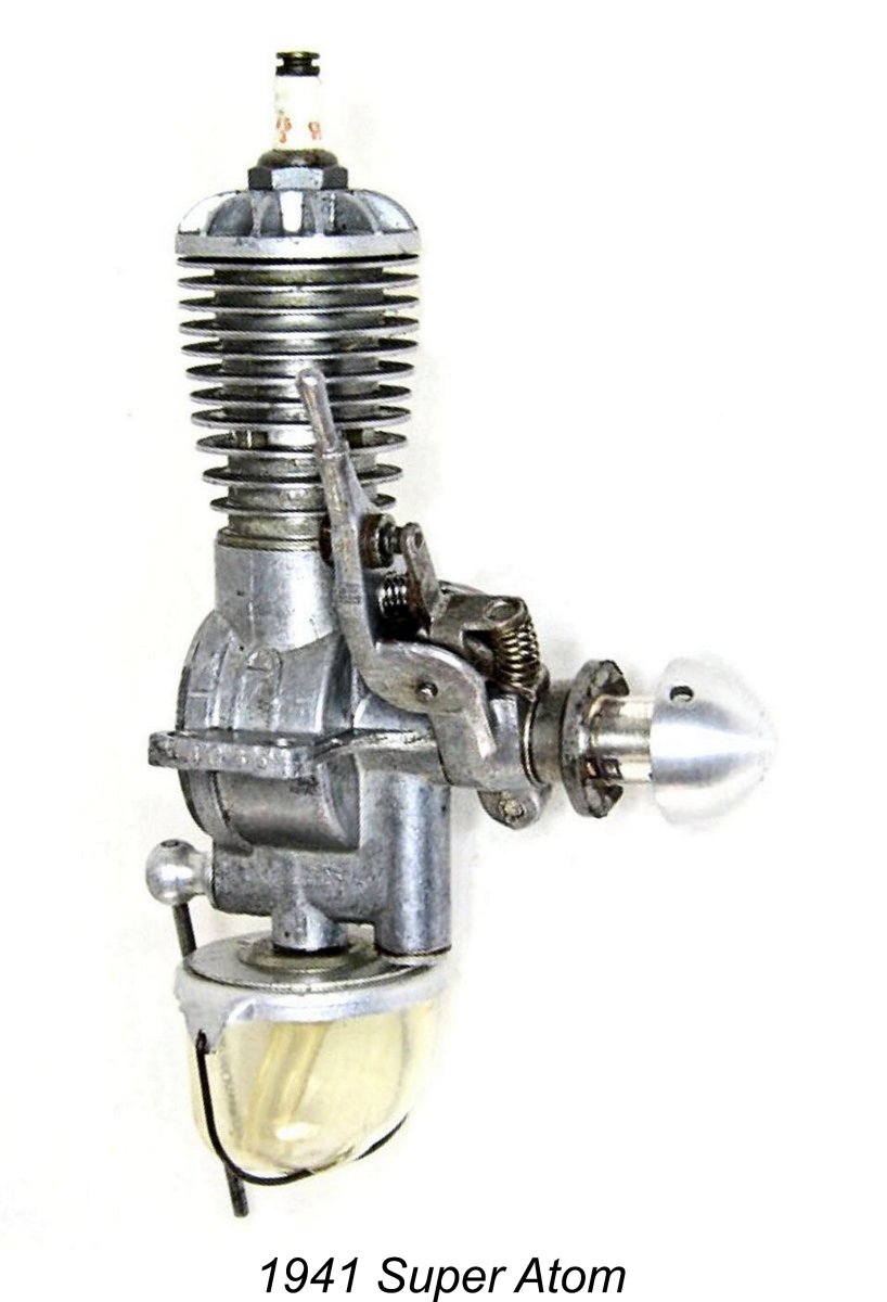
Ted learned that Ray had been consulted by the Polks in early 1941 to try to solve the problem of the under-performing 2nd model Mighty Atoms. It turned out that an error had crept into the tooling for the crankshaft, resulting in the timing of the induction port being significantly retarded. In order to salvage a sizeable inventory of pre-machined crankshafts, Ray revised the crankpin index and re-machined the induction ports. The result was touted as a “factory hop-up” as opposed to what it really was - a fix of a production error! That said, the resulting engines turned out to be the “hottest” Mighty Atoms of them all - quite literally, because the minimal cylinder finning allowed them to reach extremely elevated temperatures. For reasons to be discussed later, production of the 2nd model Mighty Atoms was relatively brief, only continuing until mid 1941. The serial numbers stamped on the rear of the case went from the 07000 range up to around 10000, at which point the numbers were relocated to the outer edge of the right-hand mounting lug. In that location, they carried on up to around 12000. It thus appears that fewer than 5,000 examples of this model were manufactured. The Third Model Atom - the Super Atom By mid-1941 the winds of change were blowing strongly in the American industrial sector. The war in Europe had heated up, while US/Japanese relations were becoming increasingly strained. It had become obvious to most clear-thinking participants in the governance of the USA that the country’s entry into WW2 as a combatant was inevitable. This resulted in a definite shift of the American industrial economy towards war-related production. The Lend-Lease program was being expanded, while military aircraft production was being ramped up in anticipation. Supplies of magnesium were diverted almost wholesale into the manufacture of aircraft and the production of munitions such as incendiary bombs. Consequently, magnesium alloys were no longer available for such non-military purposes as model engine manufacture.
Although these changes in combination represented a styling improvement which many modellers viewed positively, they were driven primarily by an operational issue which had become apparent with the 2nd model engines. They were quite “hot” runners, particularly the examples with the improved crankshafts developed by Ray Arden. The extra cooling surface provided by the new head and revised cylinder fins helped to alleviate this issue. A further change arising from the same problem was the omission of the oil retention groove and the annular relief portion of the working piston’s outer wall. The working piston was now a perfect cylinder externally. The higher operating temperatures had resulted in accelerated piston wear, and the omission of these features provided a greater compression sealing area. The prop driver/cam component was also revised, now being formed by forging as opposed to being a fairly complex machining challenge.
The revised design used a far sturdier cast plastic tank which was secured by a wire clip. A rotary sliding cover was now provided to allow refuelling without removing the tank. This revised assembly was designated the “Streamlined Tank” by the manufacturers. The air control shaft now had a ball end which accommodated the control arm. This change was apparently made to create clearance for the revised tank assembly. The 3rd model Mighty Atom was designated the "Super Atom" to distinguish it from its predecessors. It was extremely successful, probably being the best Atom of them all. Serial numbers for this model start at around 12000 and go up to around 20000. Almost as many examples were sold during its 6-month production period as had been sold for both of the previous designs together! However, this happy trend was comprehensively derailed in December 1941 by the Japanese attack on Pearl Harbour. The Super Atom During WW2 The wholesale switch of American industry over to war-related production was a game-changer. A War Production Board was quickly established to oversee this diversion of materials and manufacturing capacity. Model engines were not high on their priority list! Consequently, by early 1942 the manufacture of model engines was grinding to a halt.
Owners of the 2nd model Mighty Atom of 1940 could return their piston/cylinder/rod assemblies along with a payment of five dollars to receive a complete 3rd model replacement assembly including the revised cylinder head. In addition, the Super Atom’s “Streamlined Tank” assembly could be bought for a dollar to upgrade an earlier engine which still retained the earlier snap-on celluloid tank. The attached advertisement from the March 1942 issue of "Model Airplane News" confirms these details. This has led to the appearance of quite a few Atoms which look like 3rd model Super Atoms but use magnesium castings and sport serial numbers below 12000. If you care about such details, it’s important to realize that these are not factory productions - they’re owner upgrades. After new production began to wind down due to the wartime situation, the company evidently used up whatever parts they had on hand to assemble complete engines. Consequently, one may encounter such anomalies as Super Atoms having the 1940-style grooved pistons, for example. As a result of the manufacturer’s efforts, limited availability of the Atom was maintained for some time, although the engine’s distribution was essentially restricted to participants in the Air Youth programs who were considered to be preparing for later roles in military aviation. Even so, examples of the engine remained in fairly widespread circulation throughout the war years, doing much to keep the hobby alive during that period. The Post-War Super Atoms The reappearance of the Super Atom following the conclusion of WW2 was somewhat confused, to say the least! The first post-war advertisement by Micro-Dyne appeared in November 1945, announcing that the Super Atom would soon be reappearing on hobby shop shelves. A number of dealers subsequently began to list the engine as being available, but strangely enough Polks was not among them!
It turned out that Ray Arden was once again at the centre of it all! It seems that in 1945 Polks had been quick to request that Bard-Parker resume production of the Super Atom. However, in the interim Ray Arden had come up with the design for his Arden .099 model and had actually contracted with Bard-Parker to produce the engines, having convinced them that the Arden designs were the engines of the future. Bard-Parker had focused their energies on Arden production, setting the Super Atom to one side despite the request from Polks. Although they showed considerable patience in the face of this situation, by late 1946 the Polks’ patience had run out. They had now reached the conclusion that something was wrong. At that point they began to press the issue more forcefully with Bard-Parker, the result being that Super Atom production did finally resume in early 1947. However, it’s very clear that Bard-Parker saw the Super Atom as a second-class product by this time, consequently putting far less care and effort into its production than they had formerly.
Otherwise, the 4th model units were fundamentally similar to the pre-war 3rd model Super Atoms. The main problem was that they were far less well-made. Ted Enticknap commented that it was really hard to believe that the Arden engines and the post-war Atoms came from the same Danbury workshop! If the delay in its post-war re-introduction didn’t doom the poor little Atom, the post-war quality issue certainly did. The final nail in the coffin lid came yet again from Ray Arden, whose November 1947 introduction of the commercial miniature glow-plug doomed the spark ignition Super Atom to more or less immediate extinction. Production evidently ended at that point or very soon thereafter, with no attempt ever being made to develop a glow-plug version. As a result of the quality issue plus the direct competition from the admittedly superior Arden .099, the post-war Super Atoms failed to sell. Relatively few of them were produced by comparison with the pre-war models. Serial numbers on the 4th model engines cover the range from 30000 up into the 34000 bracket, implying that only some 4,000 examples were manufactured during a production period of well under a year. The Polks reportedly wound up with a stash of over 10,000 unused sets of magnesium castings when production ceased in late 1947. We shall hear more of these castings later .............. The Stanton Atoms
In their advertising flyer of July 1969, the major hobby retailer Stanton Hobby Shop Inc. of 4734 North Milwaukee Avenue, Chicago, Illinois announced the “discovery” of a sizeable stash of New-in-Box Super Atoms, which they were offering for sale at a price of $34.95 plus postage. These were characterised as 3rd model Super Atoms. Similar advertisements appeared in the January and February 1970 issues of “Model Airplane News” (MAN). Unfortunately, no-one connected with Stanton ever clarified the circumstances surrounding this discovery. It’s clear that someone had taken the trouble to preserve a sizeable collection of completed engines and components, but who this might have been and where the components had been stored for over 20 years was never revealed. Indications are that it must have been someone who was directly involved with the manufacture or marketing of the post-war Atoms, but there’s no evidence whatsoever to suggest an identity. The situation is greatly complicated by a consideration of the degree of variation to be observed in these Stanton Atoms. In Ted Enticknap’s well-informed view, the claim that Another problematic matter is the fact that many of these Stanton Atoms have aluminium heads and backplates, seeming from the pre-war 3rd model Super Atoms. Some even have aluminium timer frames - the example pictured in the Stanton advertisements is an example. This is a major inconsistency, since Micro-Dyne never mixed magnesium and aluminium components at any time during their manufacture of the engines. Someone other than Micro-Dyne was responsible for these “hybrids”, most of which do not carry serial numbers. At this distance in time, it seems highly doubtful that we’ll ever discover the full background story behind these Stanton Atoms. They are included here because Stanton apparently sold over 200 examples, many of which remain in circulation today. It’s important that collectors be able to distinguish them from the originals. Having now traced the production history of the Mighty Atom/Super Atom series, it’s now time to go in search of some definite answers to the question - how did these engines handle and perform in reality? Let’s begin by examining their media reception. The Atom Engines in the Media As far as I can discover, the Atom engines were never the subject of contemporary published tests. The engine’s outstanding performance characteristics evidently spread very effectively by word of mouth. Coverage of the Atoms was confined to a number of appearances in engine-related articles in the contemporary US modelling media. The Atom was first listed in the 1940 Model Airplane Engine Directory published by MAN. It made repeat appearances in both the 1941 and 1942 Directories from the same publication. The first actual commentary on the Mighty Atom came through the appearance of the 1st model of the engine in the May 1940 issue of “Flying Aces” magazine in the magazine’s regular “Logging the Motor Market” feature. This was followed up by the inclusion of the 2nd model Mighty Atom in the same feature of the magazine’s August 1941 issue. The 3rd model Super Atom was similarly covered in the November 1941 issue. The Mighty Atom was also included in Irwin Polk’s article entitled “Gas Engine Census” which appeared in the April 1941 issue of “Air Trails” magazine. The variant dealt with in that article was the 2nd model which had been introduced in December 1940. Polk made much of the revised cylinder design in that model, also commenting that the “seemingly complicated” timer placed “no load on the engine” and was “easy on the battery”. Both were completely valid claims, as we saw earlier. The continued availability of the Super Atom despite the onset of WW2 was confirmed through its inclusion in the “Logging the Motor Market” feature in the August 1942 issue of “Flying Aces”. However, that was it until after the conclusion of WW2. The Super Atom’s first post-war media appearance came with its inclusion in Edward G. Ingram’s article entitled “Construction Features of Model Engines” which was published in the June 1945 issue of MAN (while the war in the Pacific was still ongoing). Ingram devoted a fair amount of text to a very clear description of the manner in which the piston valve worked.
The final media appearance of the Super Atom that I can find came though its inclusion in the data tables which accompanied Ingram’s article entitled “Model Motors for 1948” This article was published in the January 1948 issue of MAN but was clearly compiled in late 1947, allowing for editorial lead time. We’ve seen that the Super Atom had finally reappeared in early 1947 but had failed to re-establish itself in the marketplace. Nonetheless, Ingram clearly expected it to remain available in 1948, hence its inclusion. The article appears to have been compiled prior to the November 1947 appearance of Ray Arden's commercial miniature glow-plug, since the only “hot coil” ignition engine which was included was the H&H .45 model which had appeared earlier in 1947. It’s possible that Ingram failed to fully appreciate the significance of the late 1947 appearance of Arden's new product, but I feel it to be far more likely that the article was compiled prior to the appearance of the Arden innovation. All indications are that the Super Atom went out of production in late 1947, not to begin re-emerging until the appearance of the Stanton Atoms in 1969. All of which leaves the performance question unanswered! This being the case, I’ll just have to do the best that I can using my own resources. The Super Atom on Test
My other example appears to be one of the original 4th model post-war Super Atoms made rather belatedly by Micro-Dyne, since it bears a serial number which falls into the appropriate sequence. The number appears to be 32637, although this is a bit difficult to read - the number has been eroded through a combination of use and corrosion, leaving only the final digit “7” clearly visible. Still, I’m pretty sure that the number is correct.
When setting out to actually run an engine having relatively unfamiliar design characteristics, one may reasonably anticipate some differences in the operating procedures. In such cases, reference to the manufacturer’s instructions is a very logical first step - since it’s very much in the manufacturer’s best interests that purchasers of their products meet with immediate success when first attempting to start their engines, their advice is likely to be quite sound.
Part 5 consists of reprints of the manufacturers’ instructions for most of the principal engines then in widespread use, including the Atom. Those instructions are reproduced here for the benefit of other potential operators of these highly individualistic designs. I found them very helpful when planning my own tests. I did notice one error, though - advancing the timing as per paragraph 6 is accomplished by moving the timer arm clockwise when viewed from the front! In accordance with what the instructions stated elsewhere to be a common practise, I elected to remove the standard tank and use a separate tank of greater capacity. I felt that this would greatly simplify the testing process given the number of stops and starts potentially involved. Airscrew recommendations back in the day were often quite vague - the Atom instructions said that “any 8 to 10 inch propeller” could be used. Not very helpful! The attentive reader may recall that Edward G. Ingram’s December 1946 article in MAN entitled “Model Motor Symposium” cited a range of suitable airscrews in the range of 9-10 in. diameter and 6-7 in. pitch. After due consideration, I decided that a BY&O 9x5 wood airscrew should make a good initial test prop. It seemed like a lot of prop for an engine of this displacement, but it was actually at the lower-torque end of the recommended range. The manufacturer’s general recommendations specified the use of a fuel consisting of 3 parts of white gas to 1 part of SAE 70 mineral oil. Since my usual sparkie testing brew is a 3:1 blend of Coleman Camp Fuel (white gas) and SAE 60 mineral oil (AeroShell 120), I had the manufacturer’s sanction for its use on this occasion! Thanks to advances in lubrication technology since WW2, present-day SAE 60 oil is a far better lubricant than any SAE 70 oil from over 75 years ago! The sparks were supplied as usual by one of my Larry Davidson solid state triggering systems. I have always found these systems to be both completely dependable and foolproof in operation. All that’s necessary is to ensure that the batteries are well charged beforehand. I’ve discussed these systems in detail in my separate article on spark ignition engine operation. I elected to begin my testing efforts with pre-WW2 aluminium case Super Atom no. 18100. AAT-21 Super Atom no. 18100 running L AAT-22 Super Atom no. 32637 running R
The Atom Replicas and Specials Although my primary goal in writing this article was to present the full story of the “original” Micro-Dyne Atoms, I feel that it would be remiss of me not to include at least a mention of a few Atom replicas and “Specials” which have appeared in later years. In 2003 the late Roger Schroeder commenced a 5-part series in ECJ detailing his efforts to construct an Atom from a set of original magnesium castings that he had somehow obtained. His associated research into the origin of these castings revealed that back in the late 1970's, some ten years after the Stanton effort, an individual named Ted Crouss had obtained about 10,000 sets of original castings. Presumably these were the residual castings reportedly retained by the Polks after production of the last original Atoms ceased in late 1947. Ted made extensive drawings (17 sheets, labeled "SKA"), taking his measurements from actual examples of the engines - no reference was made to original drawings. Ted then advertised and sold sets of castings along with plans and a fuel tank for $15.50 under the name TAC Aero. However, at some point after he first offered these sets, he accepted an offer to sell his remaining inventory to a firm reportedly intending to build complete engines overseas at low cost. This put an end to the TAC Aero effort. Enter Morrill-ADC. In 1984, new production Atoms were advertised at $69.95 and advance orders taken. However, Morrill-ADC seemingly never delivered any engines. In early 1986, their patient customers who Perhaps the most commonly-encountered Atom “replicas” are those manufactured by Profi in Ukraine at the instigation of the late and much-missed Woody Bartelt. They were probably made during the 1990’s, although I can’t be certain. They were reportedly constructed using original castings, presumably drawn from the 10,000 sets which Ted Crouss had obtained from the residual stocks held by the Polk brothers after the original production ceased in late 1947. The Profi replicas were generally similar to the post-WW2 Type 4 units, but were far better-made and featured a number of significant changes which demoted them from replica status to that of look-alikes. One was a switch to a conventional needle valve as opposed to the air intake control used on the originals. The other was a completely different tank which threaded onto a metal cap. The An engine about which far less seems to be known was a very well-constructed copy of the Atom built with a displacement of 0.60 cuin! This makes it a derivative rather than a replica. As the attached image will demonstrate, this one completely dwarfed the original 0.166 cuin. model. It was generally based upon the design of the Type 1 Mighty Atom of 1939. The quality of its construction was very high, but I have been unable to discover either who was responsible or how many were made. All I know is that it is mega-rare today. If any reader knows more, please get in touch!
Four such units were built by George Conrad from slightly modified original wood patterns, while Ted Belcher constructed no more than six additional examples. It thus appears that perhaps ten examples of the reproduction Atom Twin are floating around out there. Some of them have evidently been offered for sale as Arden originals by unscrupulous sellers - buyer beware! The two originals reportedly built by Ray Arden do not appear to be in circulation. Conclusion The above account of the Mighty Atom and its descendants should (I hope!) have convinced you that we’re looking here at an unusually significant model engine design. Quite apart from its technical innovation, it opened up entirely new fields of power model aircraft design. Its construction required the consistent achievement of a very high standard of precision, a challenge which its manufacturers met admirably, at least with the pre-war variants. It also demonstrated for all to see that even a sub-miniature engine (which the Atom certainly was as of 1939) could perform at a level which made it a completely practical powerplant to use. Although the Polk brothers deserve commendation for their vision in seeing a market niche and pursuing the design and manufacture of such a small engine, most of the credit for its success undoubtedly belongs to Ray Arden. This being the case, it’s a fascinating twist of fate that made Ray largely responsible for the Atom’s post-WW2 eclipse, first by submarining its post-war production in favour of his own Arden designs and then by bringing out his commercial miniature glow-plug, which spelled the end not only of the Atom but also of the spark ignition engine in general. I hope that you’ve enjoyed this review of one of the most interesting and influential model engines of the pre-WW2 era. Examples still show up fairly regularly on eBay and elsewhere, and anyone acquiring one of these little gems is assured of hours of fun! If you do acquire one, don’t just let it sit on a shelf - give it a go!! _______________________ Article ©Adrian C. Duncan, Coquitlam, British Columbia, Canada First published |
 In this article we’ll be sharing a close look at a well-known series of technically unusual model engines from the pre-WW2 era in America which broke new ground in the field of model engine design and manufacture, also expanding the scope of aeromodelling as it then stood. These were the 0.098 cuin. (1.61 cc) Mighty Atom engines which were the first commercially-produced models to be designed by the mega-talented Ray Arden. My late friend Ted Enticknap commented quite rightly that “any serious list of the 10 most influential ignition engines built in the world should include the Atom”.
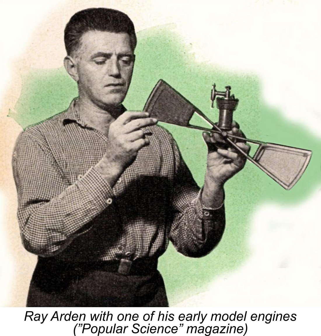 Interestingly enough in view of what was to come, Ray’s very first model engine featured a glow-plug in addition to the usual spark plug! This was not a true glow-plug engine since it still relied mainly on the spark plug for ignition. However, the rather primitive jump-spark ignition system used in the engine was inclined to misfire at the higher speeds. The glow-plug smoothed this out considerably.
 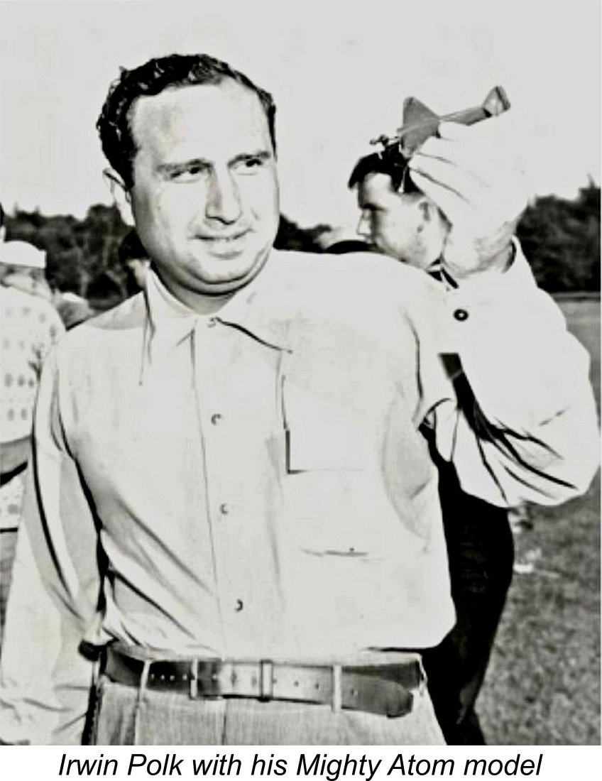 An issue which confronted anyone contemplating the design of a really small I/C engine at the time was the inescapable fact that the spark ignition units which were then the only game in town had to carry their ignition support systems along with them in the model. The weight of these systems could approach or even exceed the weight of a small powerplant. For this reason, it was obvious that any really small spark ignition engine would need to develop a specific power output (BHP/cuin.) which was significantly higher than average. It would also have to contribute minimal weight to the complete model.
 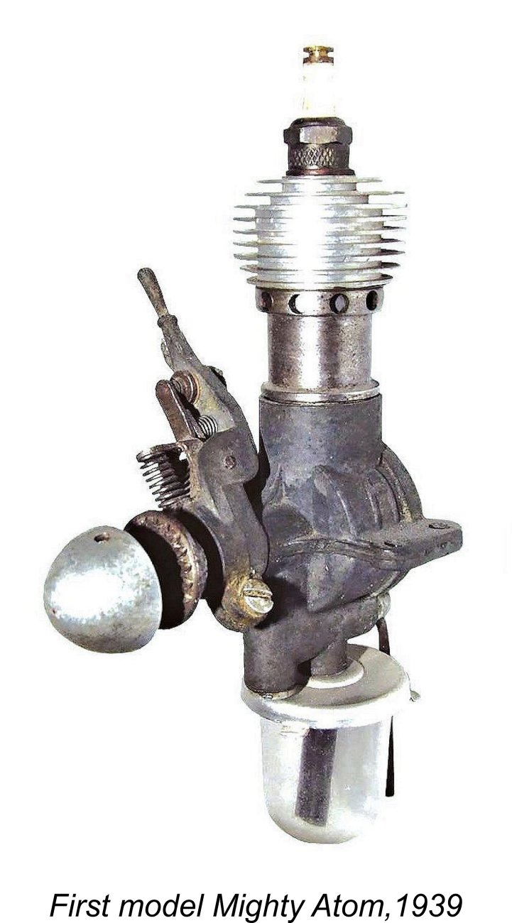 Accepting the Polks’ challenge, Ray set to work designing the new model. The engine that he came up with fairly bristled with novel features. To begin with, its “square” bore and stroke dimensions of 0.500 in. (12.70 mm) apiece gave it a displacement of only 0.098 cuin. (1.609 cc), an almost unprecedentedly small displacement for a commercial spark ignition engine, although Ray had previously constructed far smaller one-off units. The little motor weighed only 2 ounces (57 gm). However, this did not include the weight of the necessary ignition support system.
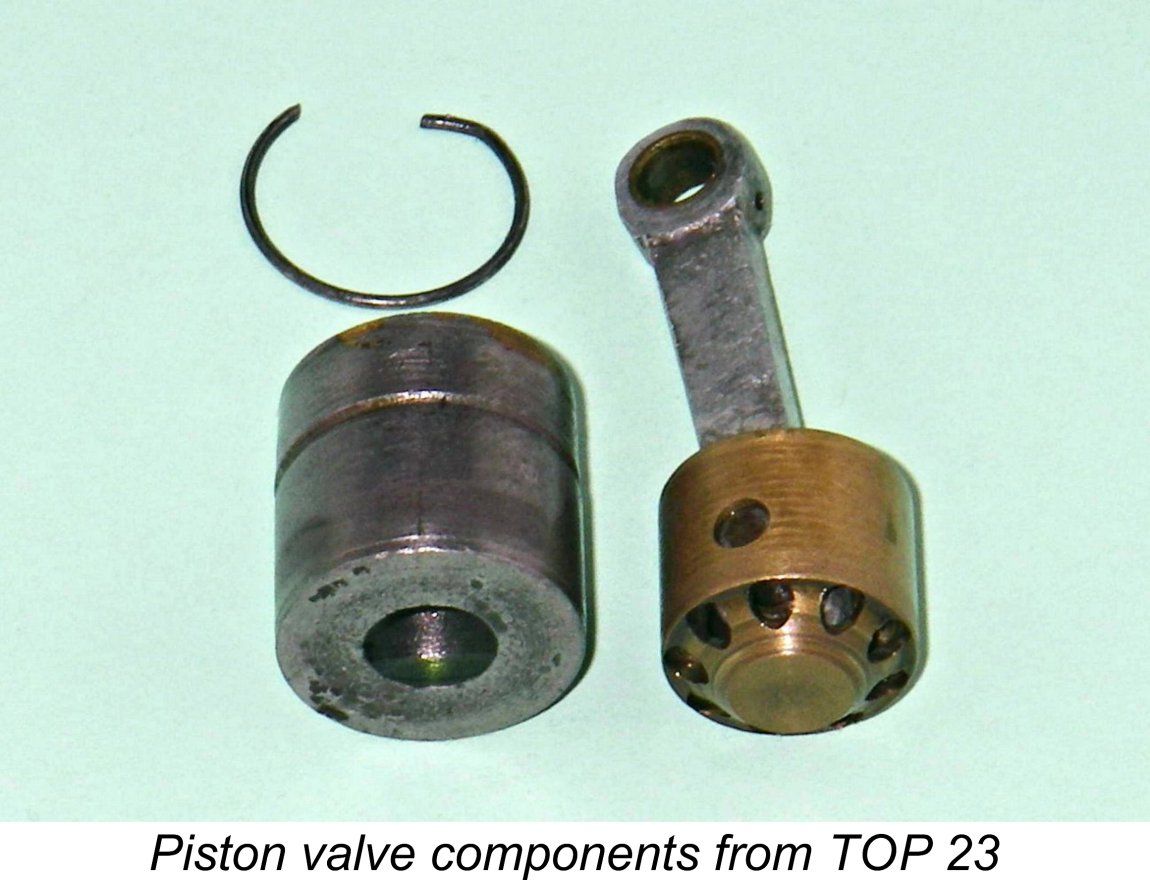 The real heart of the engine was the transfer system. The Mighty Atom used the piston port arrangement, a rather complex system which nonetheless worked very well. I’ve chosen not to dismantle my examples of the Atom, but the attached images of the similarly-designed TOP 23 from Japan should help to clarify this description as we go through it.
 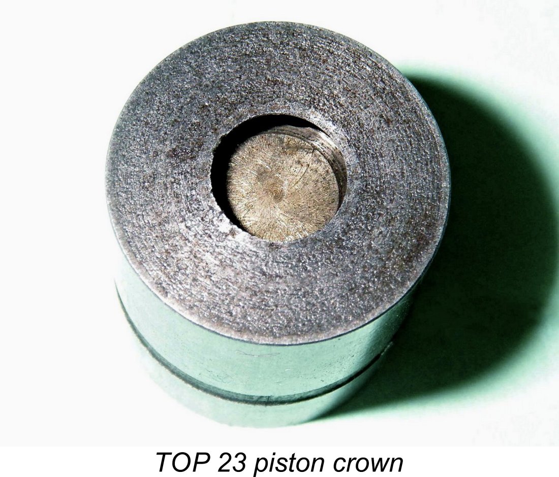 The crown of the working piston is provided with a centrally-located hole which is closed by the shuttle piston when it is pushed up within the working piston to seat against the underside of the crown. A seal is encouraged through the use of a conoidal interface similar to that used in the valves and seats of full-sized four-stroke automobile engines. Once the seal is established, further upward movement of the rod naturally causes the two piston components to rise as a unit.
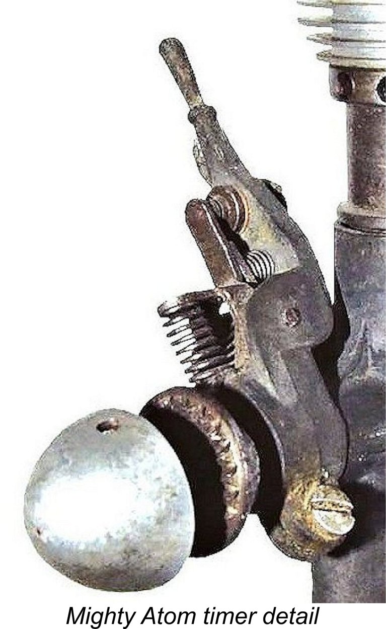 The timer was unusually complex, especially for an engine of this size. The components were assembled on a long cast base which also served as the timing adjustment arm. The main drawback to this feature was its obvious vulnerability to crash damage - the neat little handle at the outer end was frequently broken off in such incidents. One of my own examples has suffered in this way.
 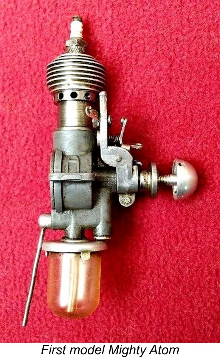 The result was a timer that only imposed operational drag during the dwell period when the points were closed and the coil was being saturated. For the balance of each revolution, the cam follower rested against its stop, imposing no drag at all upon the cam surface. Clever, or what?!? The best answer to the critics of this design is the fact that it works perfectly! The one legitimate criticism that could be levelled against it was its susceptibility to crash damage.
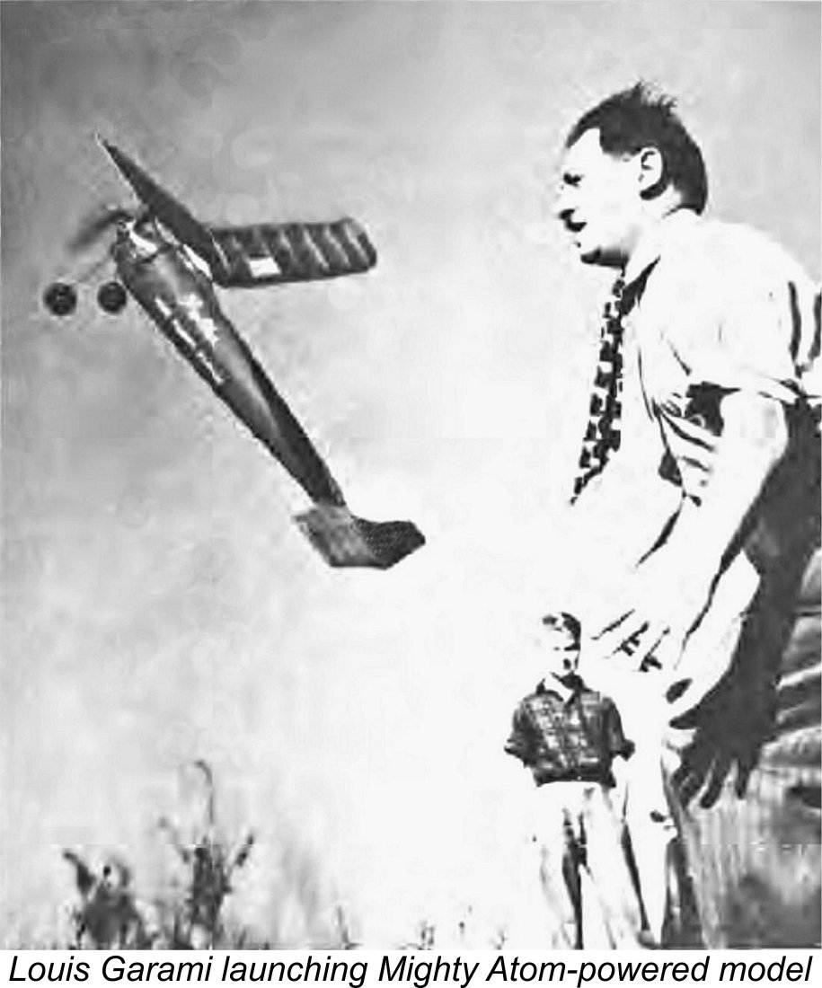 The tank supplied fuel to the underslung horizontal induction tube through a tiny 0.008 in. dia. fixed jet which also served to retain the rotary air intake valve. The tank was formed from celluloid, a somewhat unstable and highly flammable material which later fell from favour. The tank snapped into position beneath the stamped aluminium alloy top, being held there by three tabs. There was no filler hole - rather inconveniently, the tank had to be removed for filling.
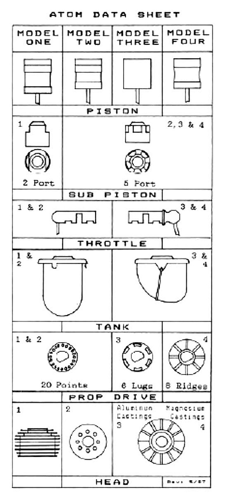 Although the original Mighty Atom was a great success and served its many owners well, the Polks could see room for improvement. The result of their further deliberations was a revised second model Mighty Atom which appeared in December 1940. This initiated a series of detail improvements to the basic design. The attached data sheet extracted from Ted Enticknap’s ECJ article provides invaluable details of many of these changes. It should be referred to frequently when reading the following material.
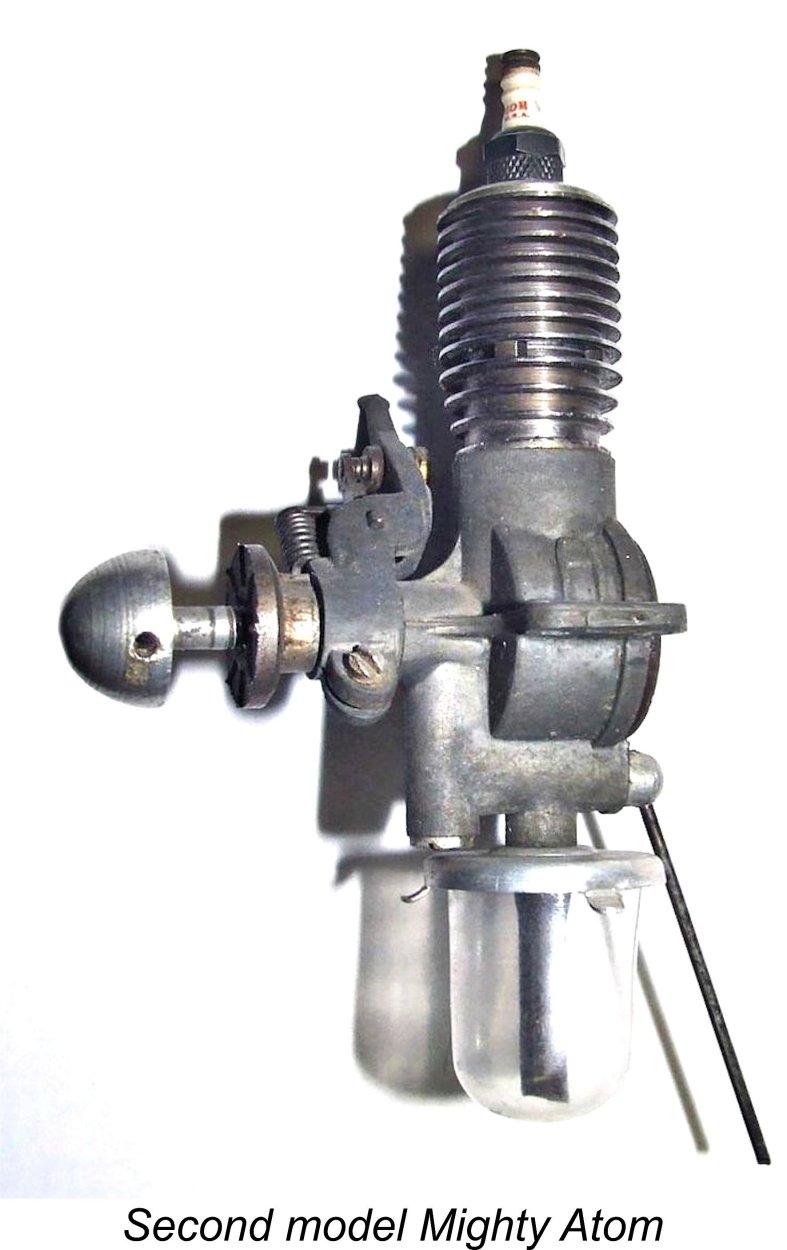 It appears that the Polks didn’t see it as being necessary to involve Ray Arden in the detailed design of this update. Perhaps as a result, a very large fly was soon found to be swimming about in this particular ointment! Expectations to the contrary, the earliest examples of the 2
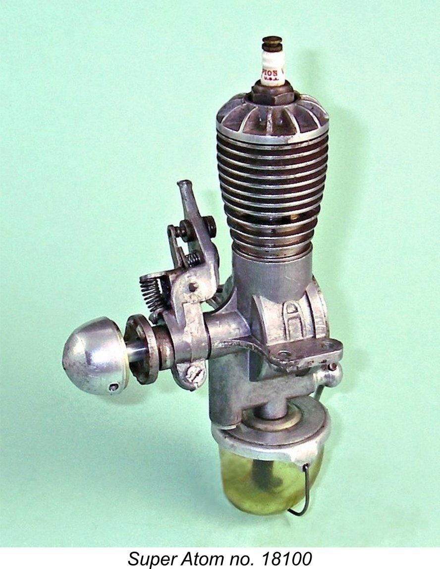 This explains the fact that the 3
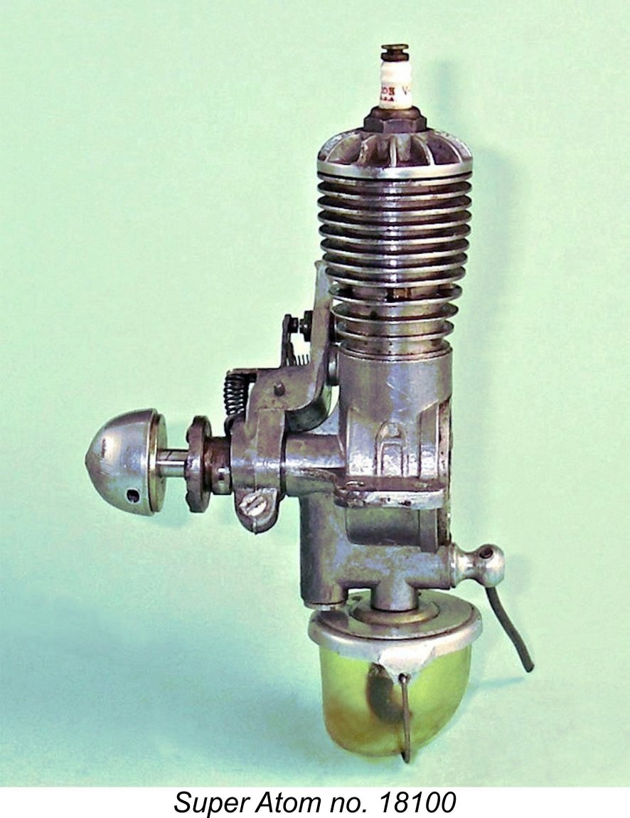 One very significant set of changes centred on the fuel supply system. As mentioned earlier, the first and second models had used a snap-on celluloid tank which had to be removed each time for filling. Given the slippery character of a gas/oil mix, this requirement led to many tanks winding up in the dirt during refuelling - not good for an engine having a 0.008 in. dia. fuel jet!
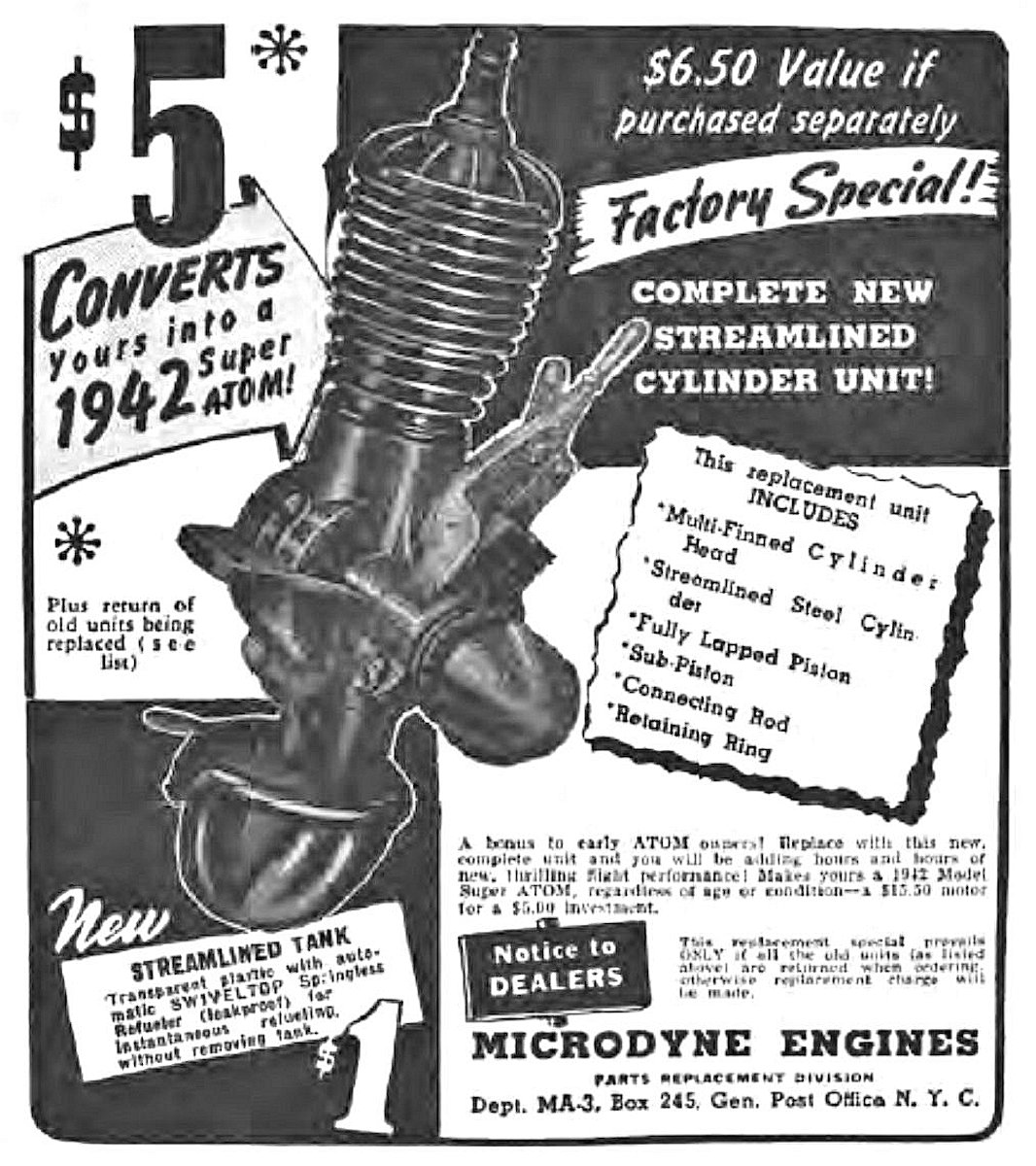 In the face of this challenge, Micro-Dyne were far more successful than most in maintaining a market presence, showing considerable foresight. Prior to the manufacturing squeeze taking effect, they seem to have built up a stockpile of finished components for the Super Atom engine. In January 1942, after America’s entry into the war, they were able to offer a conversion assembly for the engine which allowed owners of previous models to upgrade their engines to Super Atom specification.
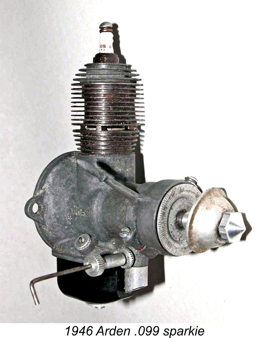 In May of 1946 the
 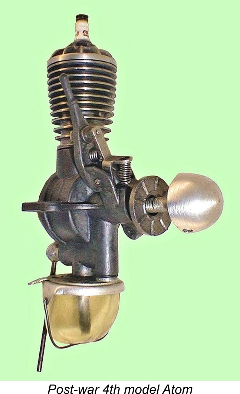 When the post-war 4
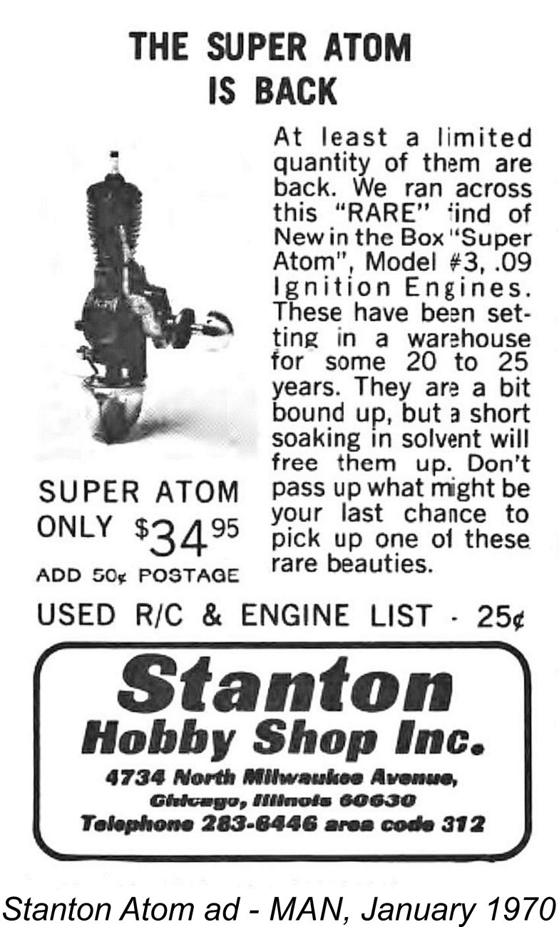 The end of Atom production during the late 1940’s wasn’t the engine’s last hurrah by any means. The engine was destined to make a further appearance, the circumstances surrounding which remain unclear even today. This was the emergence of what have become known as the Stanton Atoms.
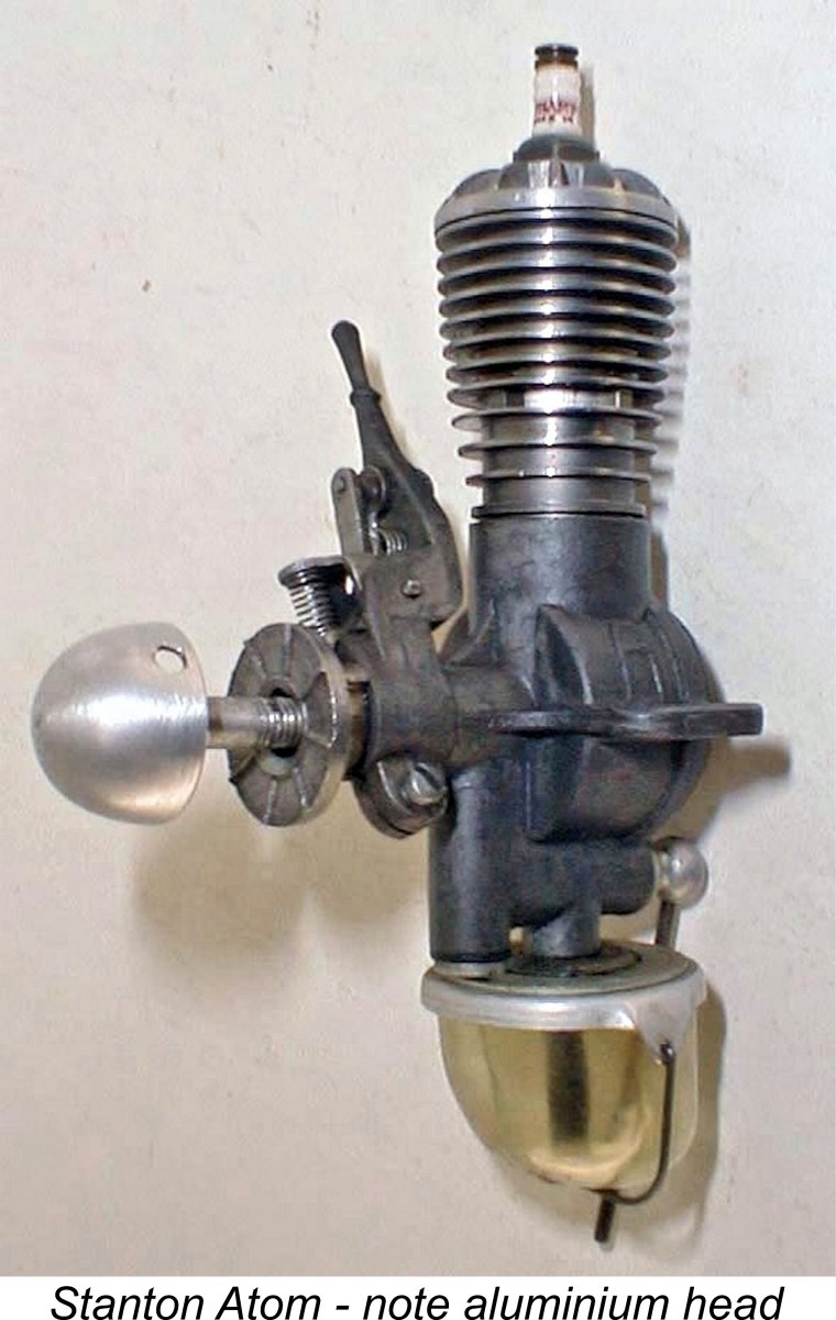 they were all New-in-Box seemed highly doubtful. They were basically 4
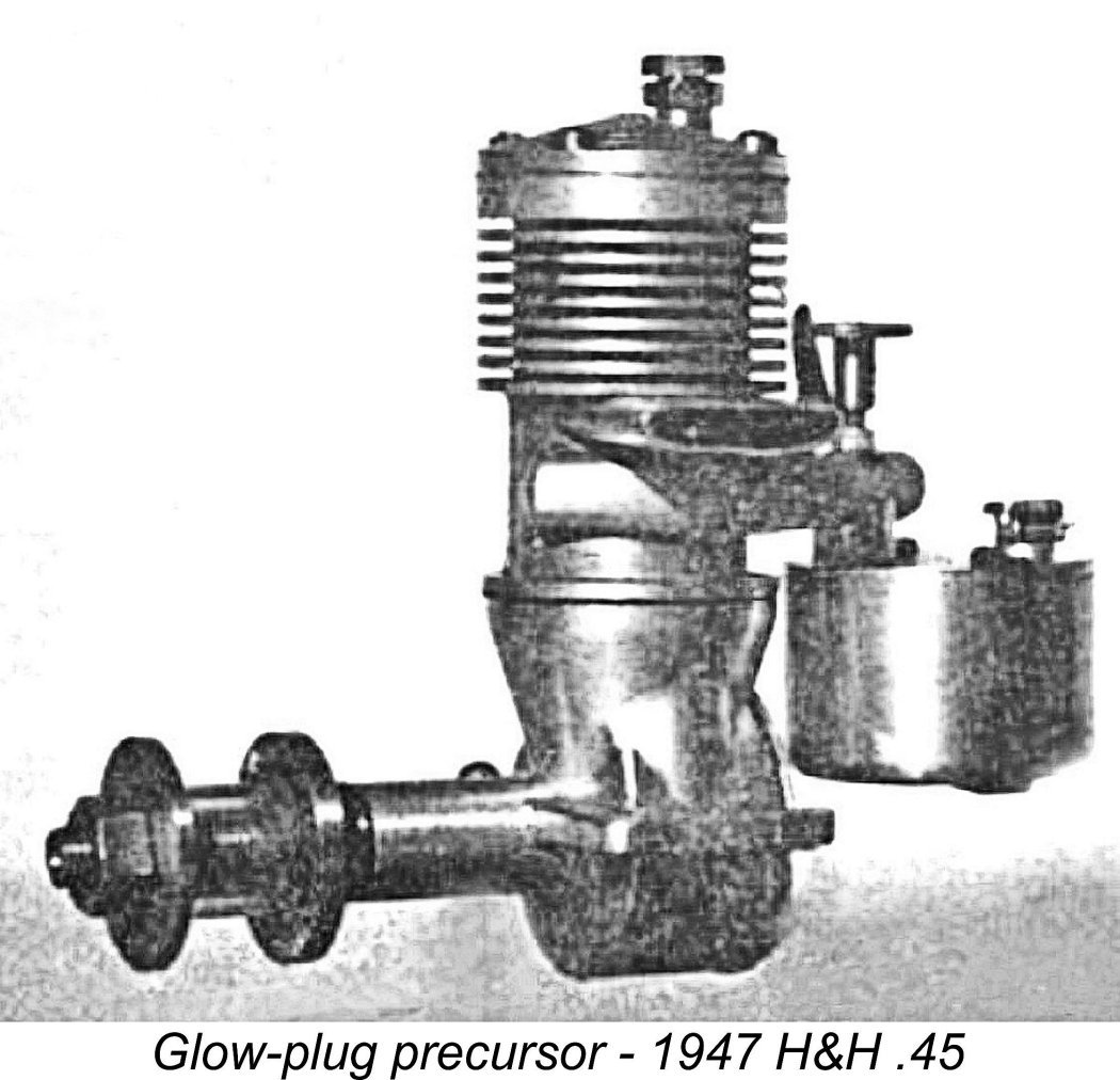 The Super Atom appeared once more in Ingram’s article entitled “Model Motor Symposium” which was published in the December 1946 issue of MAN. The performance table which formed part of this article cited a propeller recommendation of a diameter of 9-10 in. with a pitch of 6-7 in. Seemingly a pretty high level of torque development for the engine’s size was anticipated! However, the Atom was not mentioned in the main text.
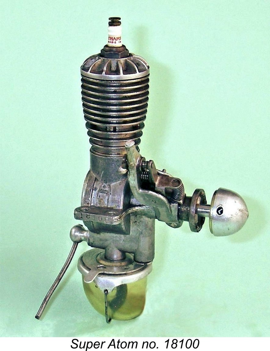 I have two examples of the Super Atom on hand. One is a very nice used example of the original aluminium-cast pre-war 3
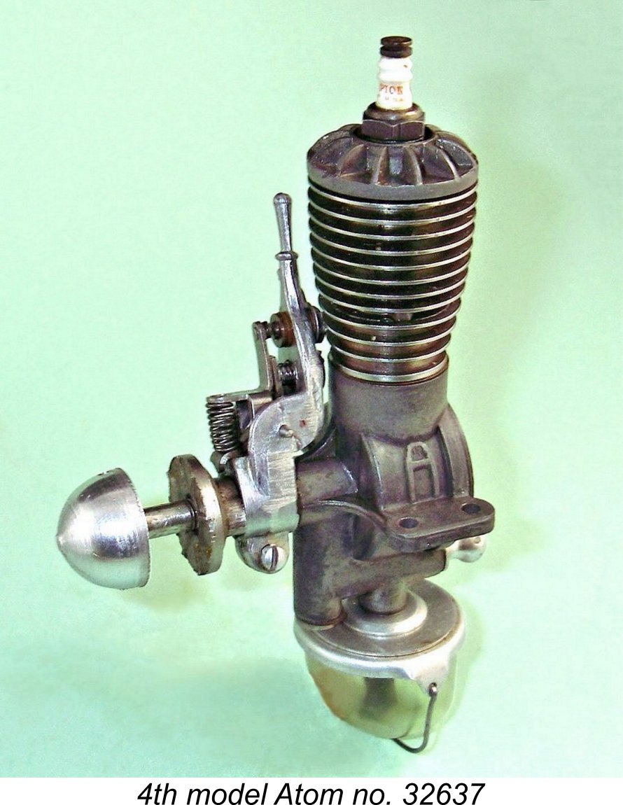 The engine has an aluminium alloy timer frame, suggesting that the original magnesium component had been broken in service and replaced by an aluminium component. It must either be one of the better post-war examples or have been subject to some expert fettling, since it's in first-class operating condition, with excellent compression. It has clearly seen some previous use, but appears to be all ready for more!
 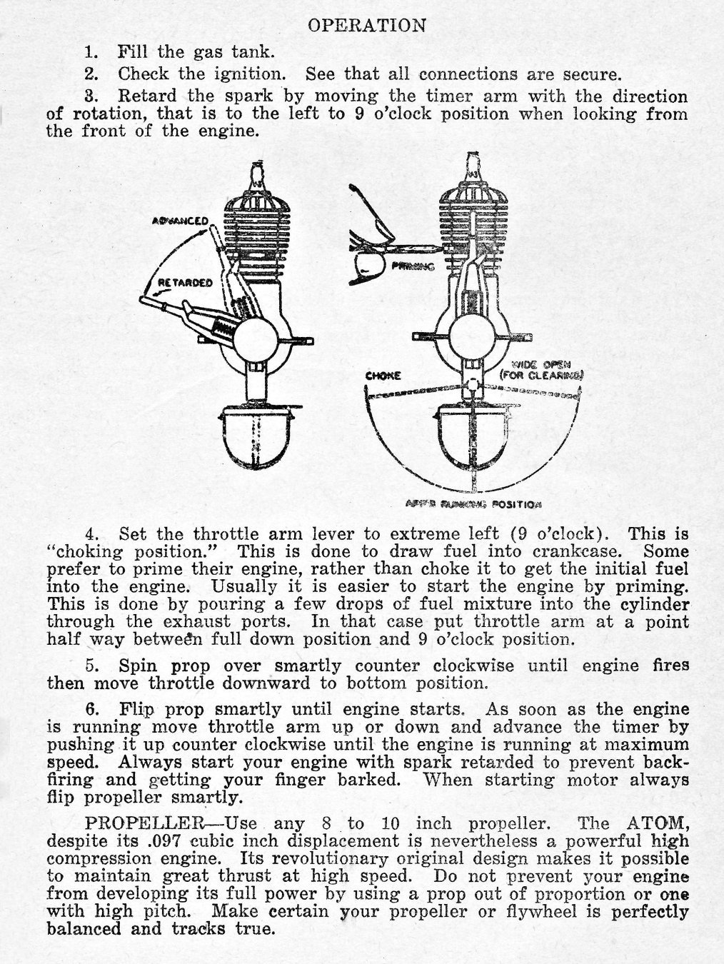 I actually have access to a set of the original Atom instructions, but there’s a very helpful reference available for those who are less fortunate. This is the invaluable little book by the late Bernie Winston (of AHC fame) entitled “
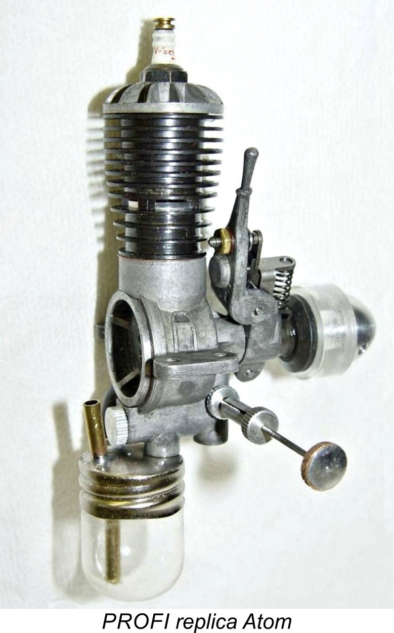 had placed advance orders were notified of delays, with an offer of a full refund in lieu of continuing to wait for an engine. This offer was repeated later the same year. However, as far as is known, no refunds were actually issued. Roger was careful to note that while his good name was used in the venture, John Morrill was neither an owner nor partner in the venture, simply acting as an unpaid technical consultant.
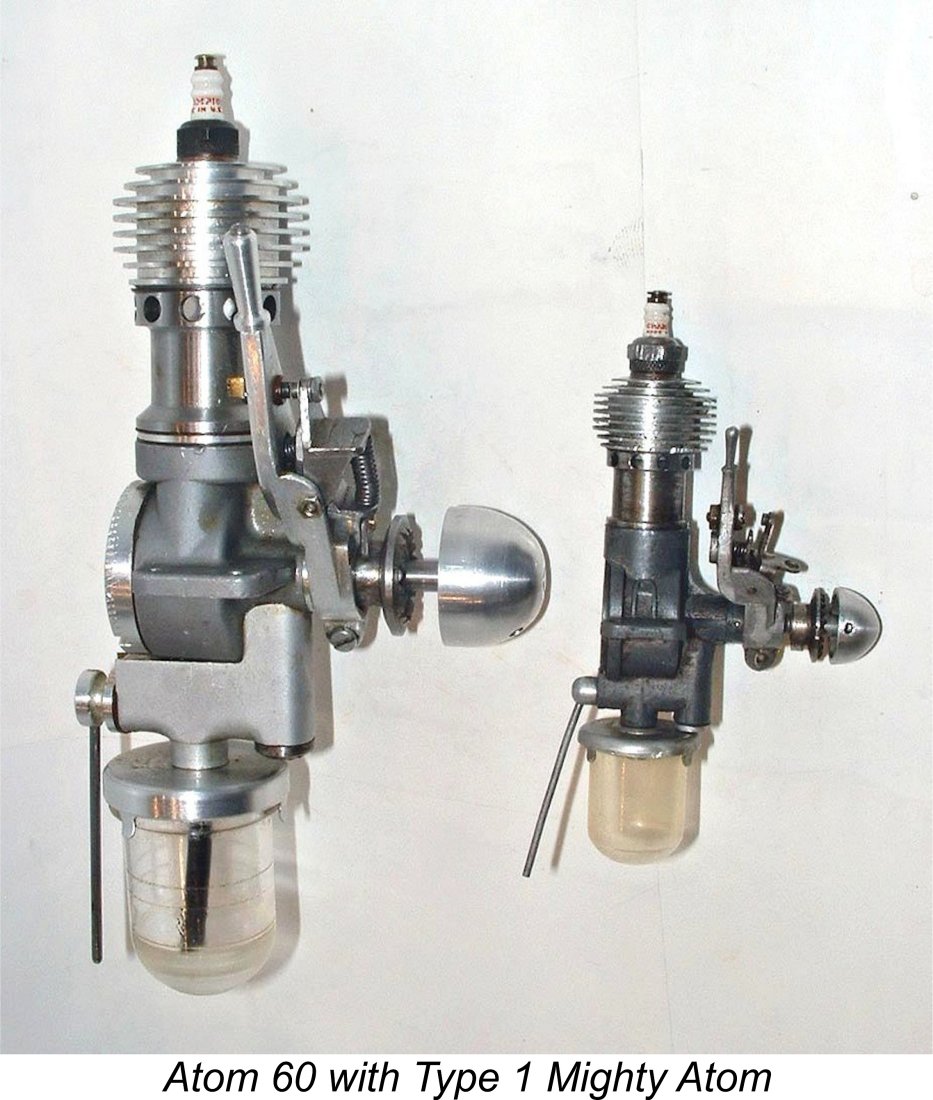 engines were extremely well made and gave a good impression of the original Atom, but there was no possibility of their being mistaken for original examples. They are nonetheless legitimate collectibles in their own right - just not true Atom replicas.
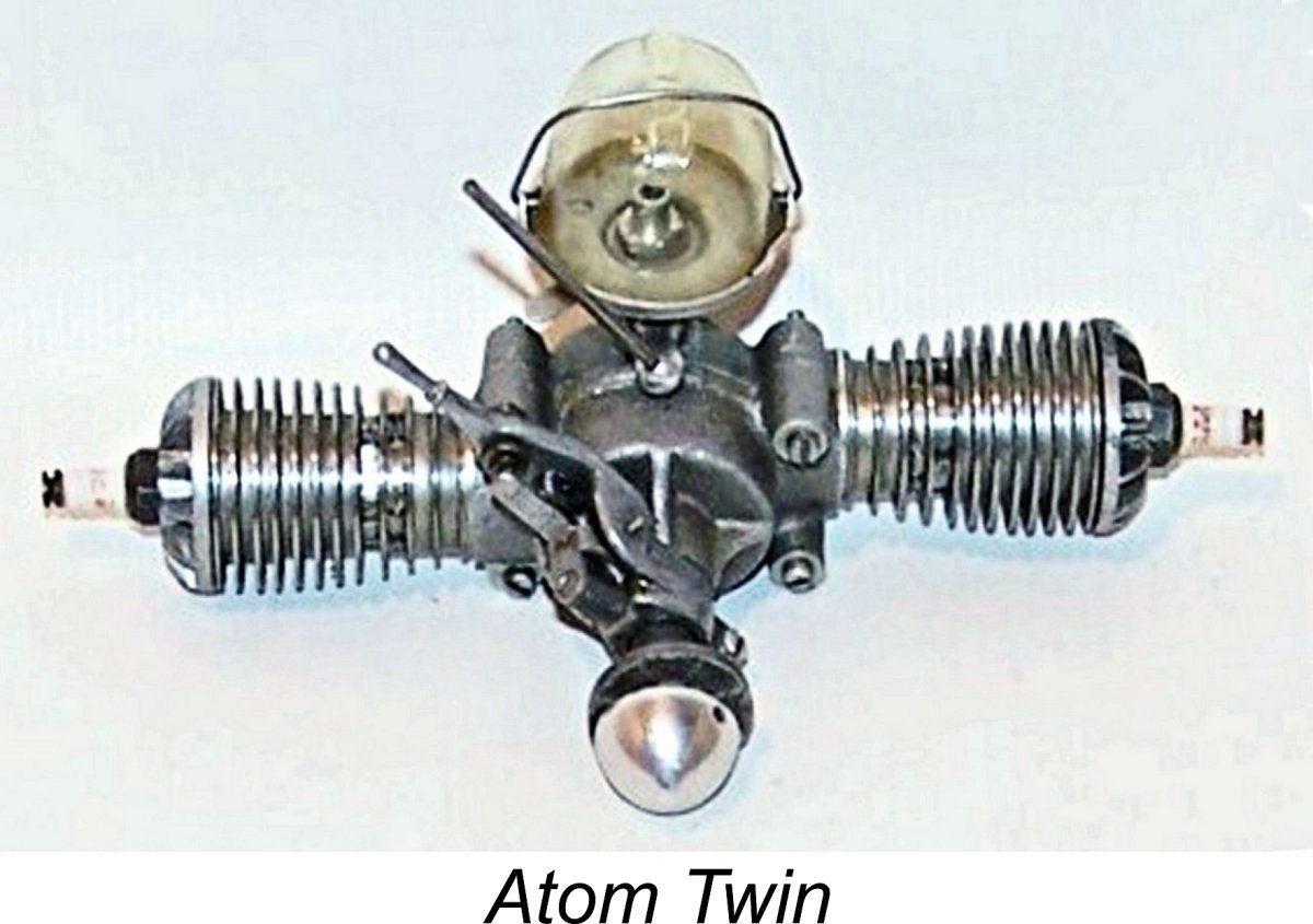 Finally, the odd example of an Atom Twin shows up from time to time. Ray Arden is believed to have built two Atom Twins back in the day, although if these engines still exist they almost certainly remain in the possession of Ray’s descendants. The twins that show up very occasionally are latter-day reproductions.
 | |