
|
|
Spark Ignition Operation De-Mystified
During the intervening decades, the collective body of knowledge regarding the operation of classic model spark ignition engines from the pioneering era was steadily eroded as their general use faded into the increasingly distant past, eventually attaining something akin to the status of legend. An enthusiastic community of old-timers and Society of Antique Modellers (SAM) members kept the spark ignition flame burning, but their numbers have steadily dwindled as the years have taken their inevitable toll. High time to do what can be done to reverse that trend and keep these fascinating old powerplants doing what they were created to do as opposed to merely collecting dust on shelves or in boxes! I suspect that many people who share my fascination with model internal combustion engines of all types are intrigued or at least somewhat curious regarding the operation of these units. After all, they ruled the aeromodelling roost for several decades, being the only game in town for power modellers prior to the advent of the model diesel during the early 1940’s. Even then, they held on to their share of the available turf until Ray Arden‘s late 1947 intervention upset the applecart. What was it like using them to power one’s models, as many people did very successfully? A tantalizing question for sure! However, it seems that relatively few present-day enthusiasts translate their curiosity into attempts to actually run one of these fascinating powerplants. In large part this is evidently due to a lack of readily-available knowledge regarding what’s involved as well as a widespread impression that the whole process is very complicated Why this should be so is a complete mystery. After all, the majority of us use spark ignition engines every day when we go places in our cars! We also think nothing of running gas-powered motorcycles, ATV's, lawn-mowers, roto-tillers, string trimmers, outboard motors, leaf blowers, snow blowers, snowmobiles and chainsaws, all of which are powered by small spark ignition engines. The common attitude towards the operation of model sparkies is a great pity, because the majority of those little powerplants from the pre-glowplug era were (and are!) perfectly serviceable units which served their owners very well in their day. If the average power modeller “back then” was somehow able to get these engines to perform effectively, as so many of them clearly did, is there any reason why today’s model engine enthusiasts can’t do the same? Of course not – what could be done then can still be done now! Indeed, the application of modern technology has actually rendered the operation of these engines far easier and more dependable than it was back in the day. Much more of this in its place below. The purpose of this article is to provide an in-depth review of the basic factors involved in the operation of a spark ignition engine as well as to dissipate some of the apprehension which seems to surround this topic. In pursuing this goal, I’ll look at both the traditional and modern approaches to this challenge. My other reason for tackling this project is to promote the preservation of these little marvels - they're far more likely to be valued and conserved if they're seen as practical operating powerplants as opposed to mere static curiosities. However, before proceeding with my self-imposed task I’d like to acknowledge the assistance provided by a number of my predecessors in this area. First, I’d like to recognize the work of my valued colleague Bill Schmidt, who in 1985 published the design of the “Schmidt trigger” which forms the basis for the majority of the technologically-enhanced spark ignition systems in use today. Bill has been unstinting in providing me with a number of highly informative comments, images, sketches and the like. Second, I’d like to thank well-known SAM competitor and former equipment supplier Larry Davidson for his invaluable assistance in helping me to assemble my own bench-testing ignition support system as described below in its place. Larry’s support made the business of creating my own very practical spark ignition test system completely painless. Last but by no means least, I’d like to acknowledge the earlier work of my much-missed Aussie mate, the late Ron Chernich, who published a highly informative “how to” article on this subject which may still be found on his superb “Model Engine News” (MEN) website. Thanks for the help, mate! Now, on with the show ………….. Some General Comments
The plain reality is that a spark ignition engine is fundamentally no different from a glow-plug model in terms of its basic mode of operation. Both types operate on the same fuel induction/transfer/combustion/exhaust cycle, and both rely upon a point source of ignition in the cylinder following pre-heating of the fuel mixture by compression. The only differences are the fuel typically used (although that too may be the same) and the means by which the point ignition source is created. This being the case, the fact that many sparkers will run quite well using glow-plug ignition should come as no surprise. The only real limitations on this interchangeability are as follows:
Another advantage is fuel cost. A sparker uses considerably less fuel (by volume) than a glow-plug unit. Moreover, it can be run on white gas or gasoline, both of which are readily available at relatively minimal cost by comparison with methanol and nitromethane. For both reasons, these engines cost very little to run by comparison with other types, assuming that rechargeable batteries are used for ignition support. The one real disadvantage of spark ignition operation is of course the need for the engine to be accompanied at all times by its ignition support system. Although the size and weight of this can readily be kept within practical limits for installation in a model, it nonetheless adds cost, bulk, weight, complexity and potential unreliability to the engine installation taken as a whole. However, if (like me) your interest in operating spark ignition engines is mainly confined to bench running (I The main point that I wish to make here is that once you have the required “box of tricks”, the business of starting a spark ignition engine is no different from the procedure applicable to a glow-plug unit. Connect the fuel line, fill the tank, set the needle, set the timer so that the points open just before top dead centre (TDC), give it a few choked flicks, switch on the ignition (as opposed to lighting the glow-plug), flick it and away it goes! The only difference is that the ignition support sytem remains connected instead of being removed after starting, as with a glow-plug. Once running, the operation of these engines is very analogous to the operation of a diesel – the needle functions in exactly the same manner to regulate the fuel mixture strength, while the timer arm performs the same function as the diesel’s compression screw by adjusting the ignition timing. Advancing the timing of a sparker using the timer arm has exactly the same effect as increasing a diesel’s compression, and vice versa. Consequently, the spark ignition engine shares the diesel's operational flexibility, being useable over a very wide range of speeds. So what’s to be apprehensive about here? Answer – nothing!! On the contrary, my good mate Maris Dislers, who has quite a bit of operating experience with spark ignition engines, has characterized spark ignition operation as being "almost as much fun as running a diesel"! High praise indeed coming from a die-hard etherhead like Maris! However, an understanding of how this unfamiliar ignition system works may be helpful in convincing the reader of that view of the matter. So let’s review the basics by working our way through Spark Ignition 101! Don't be nervous - this is very far from rocket science!! Spark Ignition Fundamentals
For many, this diagram will be all that's required to get started - you just need a coil, a condenser (aka capacitor), some wire, a switch and a battery. However, if you didn't grow up in the spark ignition era, the system may look rather mysterious and the manner in which it functions may not be readily apparent. This impression may be compounded by the fact that there is considerable variation in detail between spark ignition components. This being the case, it seems worthwhile to examine the various elements which go into the creation of a classic spark ignition circuit as depicted in Westbury's diagram. In summary, these are:
Let’s look at these elements in turn, focusing on the manner in which they contribute to the functioning of the overall system.
One point is electrically insulated from the rest of the engine, while the other is generally connected to the engine's crankcase, which serves as the “ground” for the system (also sometimes called the "earth", as in Westbury's previously-reproduced circuit diagram). The angle of crankshaft rotation during which the points are closed and hence in direct electrical contact with each other is known as the "dwell" period. The purpose of the point closure is to complete the primary circuit, thus allowing the battery to initiate the flow of current through the ignition coil’s primary winding (see below). The physical separation between the points when they are fully open is generally made adjustable so that the dwell period can be adjusted to some degree. This adjustment is made possible by making one of the points movable with respect to the other. This is usually (but not invariably) the point mounted on the timer frame, which is commonly (albeit somewhat misleadingly) referred to as the “fixed point”. The smaller the point gap, the longer the dwell period and hence the longer the duration of current flow to the coil for each revolution.
At high speeds, this delay may be enough to prevent the points from closing for a sufficient period of time to fully saturate the coil, causing a misfire to develop. This phenomenon is called “float”, which in effect turns the timer into a rev limiter. The remedies are either a smaller point gap, a cam having a longer dwell period or a stronger spring on the moving point – possibly all three. Generation of the high voltage necessary to create the ignition spark is initiated by the opening of the points to terminate the flow of battery current to the coil's primary winding. This may seem counter-intuitive, but the way in which the coil generates this high voltage will be clarified below. In almost all cases, the whole timer assembly can be rotated in relation to the crankshaft cam, allowing the crankshaft position at which the contacts open and the spark occurs in relation to top dead center (TDC) to be adjusted. This allows the operator to adjust the timing of the spark in relation to the point of maximum fuel mixture compression in the cylinder.
However, such a setting can make the engine difficult to start, since it will promote low-speed pre-ignition and consequent kick-back. Thus for starting, we rotate the timer in the direction of crankshaft rotation to cause the spark to occur later (only just before TDC), making the engine far easier to start but robbing it of power once it does start. This is called "retarding the spark". Once the engine is running, we rotate the timer assembly in the opposite direction to the engine’s rotation, thus “advancing the spark”. The optimal setting is found by ear, just as when setting the compression of a diesel. In part to ensure maximum stability of their ignition timing during operation, many racing engines of the 1940's used non-adjustable timers which were firmly clamped at all times at their running settings established by testing. Since this setting was inevitably relatively advanced, starting of engines equipped in this manner required that they be spun up to a reasonable speed using an inertia starter or equivalent before the ignition was switched on. To do their job effectively, the points need to offer low electrical resistance when closed. A downside to the provision of advance/retard adjustment as described above is that the interface between the mechanism and its mounting on the crankcase may introduce undesirable electrical resistance or even ignition failure, especially when dirt and oil are added. This was another reason why many racing sparkers from the 1940's used firmly clamped non-adjustable timers - the clamping inherently promoted an excellent electrical connection between the timer body and the grounded crankcase. This factor actually makes it desirable to connect the wiring as closely as possible to the actual points themselves, as such an arrangement reduces the system's reliance on electro-mechanical contact between the crankcase and timer assembly for the points ground connection. However, a good ground connection is still required for the high tension circuit. In the above context, an insidious factor which isn’t often mentioned was pointed out by Bill Schmidt. If you encounter a high speed misfire that isn’t attributable to any obvious cause, just look very carefully at the riveted points on your timer. Is there a bit of black residue around the riveting? If so, very close examination of the riveting will almost certainly disclose a loose joint that results in poor electrical continuity at different speeds. A word of warning – do not place the offending tungsten point on a piece of steel to pound the rivet tight again! The tungsten is extremely brittle and will shatter into many pieces. Bill tells us that he cleans the assembly with lacquer thinner and places the tungsten face down on a soft aluminum plate to reset the riveting. He then solders the rivet joint carefully and again cleans the part with lacquer thinner. You can also use a lathe tailstock to apply the required pressure to re-set the riveting without any impact being applied.
Bill Schmidt tells us that the Atom .099 with its unique "snap action" timer has about the shortest dwell period of any engine that he’s ever come across, having a figure of around 30 – 35 degrees. Atom designer Ray Arden understandably foresaw that models built for that engine would be small and light, hence being unable to carry much weight in the form of flight batteries. Reducing the dwell period was an obvious way of minimizing the required capacity of the flight batteries. In Bill Schmidt’s extensive experience, the design works OK up to the Atom’s top operating speed of around 8,000 rpm. Dan Calkin had the same thought regarding his small and relatively low-power Elfs, going so far as to wind his own special ignition coils designed to operate on a single pen cell. However, this can be carried too far! Insufficient dwell time results in a high speed stutter when the engine is peaked out because the coil doesn’t have time to become fully saturated in an If you foresee operating your engine above around 10,000 rpm, it will become necessary to increase the dwell period and hence the duration of point closure to 90 – 120 degrees of crank rotation. Some racing engines such as Doolings and McCoys which operate in the 15,000 plus rpm range will require upwards of 180 degrees of dwell to provide sufficient coil saturation time to avoid high speed stuttering or misfiring. Battery draw-down with these engines will inevitably be high, since 3 to 5 amps of current will be drawn from the battery for over 50% of the engine's operating time. The coil will also tend to run hot in consequence. Some designs went too far in this direction. The later Arden engines have a neat cam that gives a completely unnecessary 180 degrees of dwell! This really eats up your flight batteries! Why Ray Arden dropped the ball so badly here is a real mystery considering his mindful earlier design with the Atom. Arden engines do nicely in the 8 – 11,000 rpm range with 90 – 120 degrees of dwell. Bill Schmidt reports having made new cams for his Arden engines to decrease the dwell period, with very positive results in terms of battery life and no adverse impact upon performance.
The spark coil - "coil" for short, and "induction coil" for long - can take many forms, and has done so in the past. It relies for its operation upon the principle of electro-magnetic induction, whereby the establishment of an electrical current through a coil of wire wrapped around a suitable magnetically-responsive core gives rise to (“induces”) a magnetic field surrounding it. Even more importantly, this works both ways - a change in an established magnetic field enveloping a coil of wire induces an electrical current in that coil. This is the principle upon which electric generators, dynamos and alternating current transformers depend for their operation.
The coil comprises two windings (primary and secondary) of enamel-insulated copper wire wrapped concentrically around a bobbin, through the center of which passes a soft iron core. The core almost inevitably consists of a laminated stack of thin iron plates, but is sometimes formed using lengths of magnetically-responsive wire. The use of either laminations or wire is intended to prevent the core from becoming a permanent magnet. The primary winding carries a relatively high current (in the range 3 – 5 Amps) at the low voltage supplied by the battery, so it is wound using a low number of relatively thick wire turns. When switched on, this current combines with the iron core to induce the establishment of an electro-magnetic field which envelops the coil. Incidentally, the term Amp and its associated abbreviations are correctly capitalized because they represent a person's name (André-Marie Ampere, the father of electro-dynamics). The secondary winding will carry only a relatively small current, albeit at very high voltage, so it uses a very high number of thin wire turns. The ratio of turns between the primary and secondary windings will generally be in the region of 1,000:1, or more. You can make your own coil, but it's a major undertaking which is fraught with pitfalls – I strongly recommend that you buy one or scrounge one ready-made, thus saving yourself a lot of hassle! Larry Davidson used to sell an excellent compact coil which works very well indeed. However, he was forced by circumstances to cease offering these coils in 2025.
In theory, it should not matter which battery terminal - positive or negative - is connected to the coil. However, some authorities assert that it does make a difference in practise. They recommend that you try both to determine which is best, although how you measure “best” is not completely clear since the "difference" is not defined. From my point of view, either the engine runs or it doesn't .......... I've tried both orientations with equal success. The negative ground arrangement seems to be the most commonly-used configuration, as described here and as shown earlier in Westbury's diagram. That said, reader Neil Kaminar has noted that while the coil and points don't care about the polarity of the battery connection, the spark plug may do so! This is because electrons flow far more readily from a pointed electrode than from a flat one. Since electrons flow across the air gap from negative to postive plug electrodes, it follows that if one of the plug's electrodes (typically the central one) is pointed, it should be connected to the negative side of the circuitry. However, since both electrodes of a typical antique model engine spark plug are pointed, this is probably a moot point in most cases. Note also that one of the coil's two low-tension terminals is shown going directly to ground by way of the points, serving as the ground for both windings. However, the coil should work with either low tension terminal connected to ground - if connected in the reverse polarity to that shown in the above diagram, the 0.7 - 1 ohm resistance of the primary coil will have no effect on the operation of the high tension circuit since it will be on a dead end leading to the open points and will pass no current anyway. The high tension energy will still reach ground by way of the plug gap and the engine case - it has nowhere else to go.
You may also encounter a coil having two high-tension terminals. These are designed for use with twin-plug engines like the Super Cyclone. Apart from the fact that they simultaneously supply high-tension energy to two plugs rather than one, they function in exactly the same way as the more usual three-terminal components. Coils have a property known as "inductance", which is measured in Henrys (after the American scientist Joseph Henry, who did pioneering research in this field). The symbol representing this unit is the simple letter H. Without going into too much technical detail, this property causes the coil to resist a change in current flow due to an applied voltage. Consequently, when the contact points close to connect the battery to the primary circuit of the ignition coil, it actually takes a while for the current, and hence the induced magnetic field, to develop fully even though the full battery voltage is immediately applied across the primary winding.
When the points are closed, the current flowing in the primary winding induces a magnetic field which of course envelops the coil's secondary winding as well. However, the coil's inductance constrains the rate at which this current and associated magnetic field develop, keeping the rate of change well below that required to induce sufficient voltage in the high-tension winding to create a spark at the plug. There will be a voltage spike, but not enough to create a spark. By contrast, at the moment the points open, the primary current stops immediately since there is no voltage to drive it. This causes an instantaneous collapse of the magnetic field (a very rapid change indeed!) which will induce an equally instantaneous voltage spike in both windings. That in the primary winding with its relatively small number of turns will only be in the region of perhaps 150 volts with a 3-4 volt battery. However, the far higher number of turns in the secondary winding means that the induced voltage is several orders of magnitude higher – up in the region of the required 20,000 volts, in fact. This is what generates the spark.
When mounting a coil, never place it on or near a ferrous metal sheet or component, since this will interfere with the fluctuations in the coil’s magnetic field upon which its functioning depends. Also put some distance between it and the batteries. Bill Schmidt noted some years ago that the plans for the Cleveland Playboy Jr. and Baby show the coil banded tightly with the batteries. Oops …..!!
This component of the classic system is also widely referred to as a condenser. The terms capacitor and condenser are in fact synonymous – use whichever you like, and let’s not waste time debating the issue! By either name, this is in effect an electrical energy-storage component which works on the principle that when two electrically conductive surfaces in close proximity are separated by an insulating medium (called a "dielectric"), they exhibit an electrical energy-storing property called “capacitance”, which we can measure. An important point to remember is that current cannot pass through a capacitor – if it does so, the capacitor has broken down and has become a conductor. All that the capacitor can do is store and later release electrical energy – it can’t pass it.
The normal abbreviations for a micro-Farad are "μF", "uF", or "mF". The F is always a capital letter because once again it represents a person's name. The lower case "m" is an abbreviation for "micro", which may be represented using the Greek letter "mu" (μ). The use of the lower case "u" is strictly a convenience for representing μ using typography that lacks Greek letters.
As noted earlier, the induced voltage in the primary coil will be of the order of 150 volts. Without the capacitor, sparking at the points would almost certainly occur even at this relatively low voltage, since they’re still very close together immediately after opening and moreover are separated by air at atmospheric pressure. Any such sparking would erode and pit them very quickly, while running would become rather erratic. The capacitor absorbs this energy, preventing any unwanted sparking at the points. When the points close once more, the energy stored in the capacitor is released back into the primary circuit, leaving the capacitor ready to receive its next dose of induced energy when the points re-open. The optimum capacitance value required will vary with coil design and characteristics, but it is not particularly critical; any value between 0.1μF and 0.5μF should be fine. However, another manufacturer-defined property of a capacitor is its design working voltage. This is the maximum voltage that can be safely applied across it before the insulating dielectric breaks down, turning it into a conductor. For reasons lost in the mists of time, the working voltage is represented as "VW" (volts, working). For our requirements, we’ve already seen that a component rated for about 150 VW is required to deal with the induced voltage in the primary circuit when the points open. A higher rating does no harm but, as we would expect, a higher working voltage imposes a thicker or different dielectric material, requiring more plate area for the same capacitance. This will of course result in an increase in the size and weight of the component.
The spark plug, or "sparking plug" as some Brits still follow Westbury's lead by calling it, has an insulated central electrode to which the coil's high tension terminal is connected by an insulated lead. A second electrode is attached at one side to the plug body (which is of course connected to ground through the engine's structure) and is set at an appropriate gap from the central electrode. It is this gap between the electrodes which accomodates the spark when sufficient voltage is applied. The recommended spark gap varies between makers, but 0.020 in. (0.5 mm) is a reasonable ball-park figure which generally works OK with a good battery and coil combination. At least it’s a good starting point. Since twenty thousand volts is nothing to be sneezed at, the high tension wiring and the spark plug deserve some respect. The very small current involved won’t (indeed, can’t) kill you, but it certainly may tickle a bit! I recall a mate of mine who once took a dislike to his troublesome motorcycle and took a leak against the cylinder head while it was running ………….once tried, never repeated! Urine is highly conductive ………..
The spark is generated when the insulation provided by the vapor gap between the insulated central electrode and the “ground” electrode attached to the spark plug body breaks down under the application of sufficient voltage between the two electrodes. This raises a very important point to bear in mind. The distance a spark will jump in free air for a given voltage is inversely proportional to the air pressure. That's to say, you may observe a nice enough spark with the plug outside the engine, but that's no guarantee that you'll get the same (or any) spark under the increased pressure resulting from compression of the mixture in the cylinder. Only way to confirm that is to suck it and see............ Note also that the body of the plug is in intimate contact with the main engine structure which acts as the ground for the system, thus forming the second half of the electrical high tension circuit. If like many people you are connecting your ground wire to the engine mounting lug, the ground portion of the circuit starts at the spark plug thread and washer. It then travels across the cylinder head, down through the cylinder liner (often by way of the cylinder head hold-down screws) and hence down to the crankcase and the ground connection, with some gaskets thrown in for confusion in most cases. Any electrical resistance along the way robs you of high tension volts, so good, clean connections are the order of the day. The use of a multimeter to measure the electrical resistance between the plug body and the ground connection should confirm an essentially zero resistance figure if all is well. If it isn’t, you have a problem requiring resolution! Modern spark plugs for model engines use the same ¼-32 thread as that used for glow plugs. You may also encounter a 3/8-24 thread on very old engines – this If you wish to use standard ¼-32 plugs in all your engines but have some that call for the larger 3/8-24 thread, that's no problem. If you have a lathe plus the required tap and die, it's easy enough to make an adaptor that threads into a 3/8-24 cylinder head socket and is in turn centrally threaded to take a ¼-32 plug. Many model engineers have successfully made their own spark plugs, with threads cut to suit the application – the truly amazing sub-miniature sparkers of Ray Arden come immediately to mind as examples of this. The illustrated example (which appears here larger than actual size!) had bore and stroke dimensions of 0.125 in. (3.175 mm) apiece for a displacement of 0.025 cc (0.0015 cuin.)! While there have been smaller diesels, I doubt that anyone else got anywhere near that figure with a sparker! Reportedly the little jewel turned its custom-made prop at 5,000 rpm!
If you check out old magazine plans from the Good Old Days, you’ll find designs using a 4.5 volt "cycle battery". You'll also see the use of two 1.5 volt dry cell batteries wired in series for 3 volts. Westbury's previously-reproduced circuit diagram shows a 4 volt battery. Today, you might see reference being made to wiring three rechargeable NiCad (nickel-cadmium) or NiMH (nickel metal hydride) batteries in series for a total of 3.6 volts. That's the set-up that I use myself for bench-testing. But NiCads are actually becoming hard to find as various lithium-based cells have become all the rechargeable rage. Confused? There's no reason to be! The truth is that there's no magic involved here - with typical miniature coils designed for model use, any voltage between 3 and 4.5 volts will work just fine with a well-built system having solid connections. It's just a matter of finding a battery combination within that voltage range that meets your specific needs and can deliver the required 4 Amps or so for a sufficient period of time.
Bill advises that the CR123 battery seems to work OK with a well-connected system and a good coil. A 3.7 volt 4-600 mAh Li-Po (lithium-polymer) battery works even better with that extra 0.7 volt and is about as light as you can go. However, Li-Po batteries do have a downside, which is the risk of fire if the charging process is not carried out absolutely correctly. In addition, an inadvertent short-circuit can also create a fire hazard. It was this incendiary tendency of Li-Po batteries which caused the cell phone fire scare of a few years back - the things can burst into flames for no apparent reason! One of my modelling acquaintances lost his garage to a fire caused by one of these batteries in his R/C model. Information on this topic can be found here. Use with caution! Personally, I won't touch them. In a classical system such as we are describing here, the decisive voltage requirement is dictated by the coil, which will have been designed to operate at a specific primary voltage and whose resistance governs the maximum current generated through the application of that voltage. Apply too much voltage and you risk burning out the coil. This can also happen if the correct voltage is continuously applied for too long, since the flow of current through the coil also generates heat in the winding. Coils are intended to receive intermittent current from the battery rather than a continuous flow. We've previously covered the topic of a coil's inductance, which causes the coil to resist a change in current flow due to an applied voltage. We saw that when the contact points close to connect the battery to the primary circuit of the ignition coil, it actually takes a while for the current, and hence the induced magnetic field, to fully develop even though the full battery voltage is immediately applied across the primary winding. Once the current and associated magnetic field are fully developed, the coil is said to be electro-magnetically “saturated”, hence being ready to provide its best spark. At that point, further application of the primary voltage has no effect whatsoever other than to drain the battery and heat the coil windings – not a desirable situation. What this means to us is that at the engine’s running speed, the real time during which the points are closed (set by the dwell period, remember?) needs to be long enough for the primary coil current to build up to something approaching the maximum, ensuring that the associated electro-magnetic field also approaches the maximum. However, additional time beyond that point is not desirable, since it accomplishes nothing other than to drain the battery by heating the coil, which we don’t want. During hand-starting by flipping the prop, the points will inevitably remain closed for a considerably longer period of real time during each revolution than they will when the engine is running at a far higher speed than that achieved by hand-flipping. Consequently, the time during which our battery will be supplying current to the coil for each revolution during starting is going to be way longer than is necessary for saturation of the coil. This is good in one sense in that the coil will always be fully saturated for spark generation during starting, but the situation is not good at all for battery life since the inevitable battery drain beyond that required to achieve saturation represents wasted energy which achieves no purpose. Our objective is to get as much energy into the coil's electromagnetic field for each cycle as its design allows without wasting battery power. As we approach the flattening top of that exponential curve of current verses time through an inductance, the coil’s electro-magnetic field is fully developed - exactly the condition which we wish to achieve. At that point, the application of additional current simply represents a waste of battery power which does nothing to improve the coil’s readiness to supply the necessary spark voltage. In fact, all we’re doing is heating the coil, which does neither it nor the battery any favors. This is the situation which will inevitably arise during starting with its relatively lengthy dwell time for each revolution. Because of this extra starting drain on the battery, you will often see provision made in a model for a "booster" battery to be plugged into the circuit for starting purposes. This is simply a higher capacity battery of the same voltage which is connected in parallel across the normal battery so that the applied voltage does not change (which would damage the coil). Its purpose is purely to reduce the load on the lower-capacity flight battery while starting, thus extending its airborne life. Once the engine is running and has been set, the booster is disconnected and the flight battery takes over. Some have written that the current drawn is less when the engine is running. This is not strictly accurate. It would be far truer to say that the average coil current draw is lower when the engine is running because the dwell duration is closer to optimal and we are not wasting nearly as much energy simply heating the coil at maximum current draw as we are during starting. Another misconception that should be laid to rest is the notion that demand on the battery rises with increased engine speed. This is simply not true - the proportion of engine running time during which current is drawn from the battery is set by the dwell period, hence remaining the same regardless of speed. At higher speeds the current is certainly drawn more frequently since there are more revolutions in a given time, but this is balanced by the fact that the time over which current is drawn for each revolution goes down proportionally with increasing speed. So power draw from the battery is essentially unaltered by changes in engine speed.
This is an essential item for several reasons. First, the point actuating cam assures that the contact points are open most of the time, preventing current from continuously flowing from the battery to the coil. However, if the engine should stop with the points closed (as they very well may in a model on the glide), the battery will send a continuous current to the coil. Not only will this drain the battery, but the coil will be in danger of overheating and potentially burning out. So the switch should be open at all times when the engine is not running – the first thing that one should do after retrieving the model is open that switch!
However, the use of such an automatic switching arrangement does not eliminate the need for a manual switch! On the contrary, the switch retains two very important functions which a timer or auto-switch will not supersede. First, it provides an instant means of shutting the engine off if a problem unexpectedly develops while the engine is running. Signs of developing mechanical distress or indications that the engine is coming loose in its mounting both call for an instant shut-off, which the switch facilitates. And secondly, in a bench-testing situation in which one will be trying different props, etc., it’s obviously a huge advantage to be able to stop the engine at will without changing any settings once a particular run has yielded the required information. The switch can be placed in a couple of locations within the low-tension circuit - either between the coil and battery or between the battery and the ground. In a classic circuit, the switch must obviously be capable of passing the full primary coil current, which will be in the vicinity of three to five amps at battery voltage. Many people use a toggle switch for this purpose. Bill Schmidt strongly recommends the use of a pull-on, push-off automotive switch rather than a toggle. Apart from the fact that this is far less easily triggered by accident, it also allows for an instantaneous knee-jerk reaction to any developing problem. You don’t have to think about which direction to flip the toggle – just slap that switch!
As mentioned above, the primary circuit of a classic spark ignition setup is going to have to carry three to five amps at battery voltage. The high tension lead will be at 15,000 to 20,000 volts above ground and will be vibrating like crazy during operation, so good insulation and flexibility are both essential. For the high-tension wire, you can't beat the sort of stuff used for electronic test equipment leads. Test-leads spend their entire life being bent, tugged, pulled, tied in knots and stepped on while quite possibly being exposed to some rather inhospitable working conditions. Accordingly, they are made with lots and Today, this insulation is generally silicon-based and so will be unaffected by exposure to a variety of oils and solvents, hot or otherwise. Naturally, there is an extra cost involved, but it is not prohibitive and you can buy this wire by the meter at any reasonably stocked electronics warehouse in black and red at the very least. While modern materials are fantastic in functional terms, old sparkies were hooked up with a wire whose insulation was woven and impregnated. There are virtually no advantages to using this, except that it looks cool! The modern equivalent is called "push-back wire" and amazingly it is readily available as it is used extensively for wiring and rewiring vintage electric guitars. Its major advantage is that you don't have to strip the ends to solder it up. You just push back the insulation to expose some bare wire, solder up, then if necessary push the insulation back down the wire. All very neat, and it really looks the part on a vintage sparkie! You can buy it by the roll or by the foot from luthier supply houses like Stewart-MacDonald. Operation OK, we’ve now looked at all the elements of a classic spark ignition system as used back in the day. How do they all work together? Pretty simply as it turns out, once you’ve grasped the individual functions of the various components as set out above. Let’s take a walk through one complete cycle, using the following diagram of a classic battery-and-coil system as our road-map. Remember that "ground" is the engine crankcase.
If we start at top dead centre (TDC) just after the ignition of the fuel mixture in the cylinder, the points are open and no current is flowing to the primary circuit of the coil. The magnetic field surrounding the coil has all been dissipated and the secondary coil has been discharged to ground through the spark plug. The coil is therefore "resting". The expanding gasses in the cylinder drive the piston downwards, just as in any other two-stroke internal combustion engine. The exhaust ports open to discharge the exhaust gas, after which the transfer port opens to re-charge the cylinder with fresh mixture. The cylinder ports close and the rising piston begins to compress the fuel vapor in the cylinder. So far, it’s all completely familiar. At some point, generally well after bottom dead centre (BDC) is reached and the piston has begun to rise once more, the points close to initiate the dwell period. This triggers the flow of electrical current from the battery to the primary winding of the coil, which in turn causes the progressive establishment of an electro-magnetic field in the coil. Because of the coil’s inductance, it takes much of the engine’s upward compression stroke to bring the current up to somewhere near its maximum and establish the coil‘s full electro-magnetic field. Remember, we're talking milli-seconds here! As the piston compresses the fuel mixture in the cylinder and approaches top dead centre once more, the points open, instantly terminating the flow of current from the battery through the primary winding of the coil. This causes the equally instantaneous collapse of the coil's electro-magnetic field. The consequent very rapid change of magnetic flux (from maximum to zero) surrounding the secondary winding of the coil induces an instantaneous high voltage spike in that winding which can only be discharged to ground by the completion of the secondary circuit. The design of the coil is such that the induced voltage in the secondary coil is sufficient to break down the resistance of the vapour gap between the spark plug electrodes. The accumulated electrical energy reaches ground by jumping the gap in the form of a spark which ignites the compressed fuel mixture. And there we are back at TDC with combustion initiated, the points open and the system all ready to begin another revolution! Of course, the collapse of the electro-magnetic field in the coil when the points open also creates a voltage spike in the primary circuit. That circuit has far fewer turns than the secondary coil, so the induced voltage is far lower. Nonetheless, it would be sufficient to cause arcing at the points, which are still in very close proximity at this stage immediately after beginning to open. This is where the capacitor earns its keep – it absorbs the electrical energy which would otherwise try to jump the gap between the points and cause arcing. The stored electrical energy is released back into the primary circuit as soon as the points close once more during the following cycle. Modern Transistor-Based Circuitry Hopefully, the above discussion has answered most questions about how it was done in prehistoric times. At the time when I began the research for this article, my only previous spark ignition operating experience dated back to over four decades ago, when curiosity led me to get an old O&R sparkie going using the above classic technology, capacitor and all. Since then, I'd been primarily a diesel user, with some glow-plug time thrown in. So what has changed since then? Well, actually quite a lot - I was amazed! I was well aware of the long-standing general agreement that the timer/ignition points are the weak link in the classic spark ignition system. This is because they are so susceptible to dirt, oil, contact pitting and other aggravations which tend to increase their electrical resistance when closed. This in turn reduces the primary coil current and associated induced electro-magnetic field, leading to a weak or unreliable spark. Because of the constant hammering to which the points are subjected, tungsten has been the material of choice, and it is not a great conductor to start with. Clearly, the points were the system element upon which the search for improvements should be focused. It was recognized almost from the beginning that the ideal fix for the above problems would be to somehow isolate the points from the primary circuit. However, for many years there seemed to be no way of accomplishing this. The seeds of the breakthrough were eventually sown during the 1960's as cheap compact transistors became increasingly available. It was realized that it should theoretically be possible to keep the engine timer assembly as-is, along with all its challenges, but minimize the adverse effect of those challenges by using a high-speed power-switching transistor to directly control the battery current to the primary winding, employing the points to do no more than switch the transistor on or off. Confining the points to this switching function would require that they pass a current of only a few mA as opposed to the 3 to 5 Amps involved with the classic circuit. Consequently, conductivity limitations would be far less of an issue as long as there was some level of conductivity. In theory, the effect of dirty points, oil, etc, should be greatly reduced or even almost totally eliminated. The developing idea was that the sole function of the points would now be to bias a power switching transistor either "on" or "off". When "on", the transistor (as opposed to the points) would pass all the current required by the ignition coil's primary circuit. When "off," no current could pass through it. This arrangement would completely isolate the points from the coil's primary circuit, thereby protecting it from the previously-discussed 150 volt "spike" from the primary winding when the points first open. Consequently, the capacitor would no longer be needed to protect the points - the primary winding would simply discharge directly to ground.
Bill's accompanying sketch above at the left shows the main features of the system. The presence of the 18-22 ohm resistor keeps the current through the points down to the few mA required to perform the transistor "tickling" function. The 10K ohm resistor in the high-tension lead is only required if R/C operation is envisaged. It acts as a suppressor to minimize interference with the radio transmissions which control the model. It must be located very close to the plug itself in order to perform its function.
Of course, the passage of time may result in the disappearance of some of these equivalents from the market and their replacement by others. You'll need to research the equivalency question at the time when you're planning to construct your own system. It's important to use quality components. Bill comments that the "clone" items formerly sold by Radio Shack (now The Source) and made who knows where were failure-prone and hence not really recommended. Best to go to a reputable speciality electronic component supplier. The things only cost a few dollars, so why cheap out?!? The functioning of the system is extremely simple. The E (emitter) terminal of the transistor is connected to the positive pole of the battery, supplying both the points circuit and the primary coil circuit. When the low-amperage circuit through the points is completed by their closure, the resulting flow of a very small amperage current from the B (base) terminal in Bill's drawing triggers the simultaneous flow of current at far higher amperage from the C (collector) terminal and thence through the primary winding of the coil. When the points open, the cessation of current flow through the B terminal also terminates the flow of current though the C terminal, thus instantly eliminating the current in the coil's primary winding. The ignition process then proceeds exactly as in the case of the classic system. The 150 volt spike in the coil's primary winding simply discharges to ground, bypassing the points completely. The utter simplicity of this design, requiring only one transistor and one resistor as well imposing far lower demands on the points, quickly made it the system of choice for the majority of those who were still running spark ignition engines. Bill deserves great credit both for designing this system and for sharing it so freely with the rest of us! With a small resistor of around 20 ohms on the base terminal of the transistor, the points experience only about 50 mA of current flowing through them at battery voltage. The previously mentioned coil-induced 150 volt "spike" in the primary winding no longer affects the points when they open because they are no longer part of the coil's primary circuit, which simply discharges to ground. Consequently, burning and pitting of the points are virtually eliminated, making the inclusion of the bridging capacitor unnecessary. Better yet, Bill tested the design during the development phase, finding that the points “tickle” circuit would actually tolerate up to about 95 ohms resistance (read dirt and oil!) before it would cease to switch the transistor off and on. Evidently the amount of current necessary to activate the switching function is very low indeed! In terms of system reliability, this represents a major improvement - the system can tolerate a significant amount of dirt and oil before it ceases to function. Since 1985, there have been some further improvements to the system as originally designed by Bill Schmidt. Perhaps the most notable of these was Larry Davidson’s SSIGNCO (Solid State Ignition & Cut-Out) module. This functioned pretty much along the lines of Bill Schmidt’s original design but included added circuitry built in that opened the primary circuit automatically after the engine had been stopped for more than 2 seconds. This of course completely eliminated the potential problems of excessive battery drain and coil overheating if the engine should stop with the points closed and the transistor accordingly left "on". The action of cycling the points by re-starting the engine automatically switched the circuit on again. Very elegant!
A number of approaches to the complete elimination of the points have been tried successfully, including the use of a Hall effect power-switching transistor, which works like the points-based system but is switched by a current generated by the crankshaft-timed movement of a small magnetic field and associated coil rather than by the direct establishment of a primary current by the points. Moreover, an increasing number of more recently-manufactured engines (including some replicas) are being produced with Capacitor Discharge Ignition (CDI) systems. However, I’m sure that most serious enthusiasts would want to use the points which were supplied with their classic spark ignition engines. My intention here is to help owners to run their old classic sparkies just as they were delivered all those years ago, points and all! That having been said, I realize that some readers may well end up operating sparkies which use CDI ignition - I have done so myself! This being the case, it seems worthwhile providing a little basic information on such a system, a schematic of which appears above at the left.
The opening of the gating transistor (Silicon Controlled Rectifier, or SCR) to initiate the capacitor discharge is triggered electronically by a separate coil (the trigger coil in the accompanying diagram) in which a voltage is induced by a small magnet rotated by the engine's crankshaft. The trigger coil thus assumes the role of the points, albeit with no contact being involved. Most full-sized CDI systems use a magnetic rotor to charge the capacitor (the excitor coil in the accompanying diagram). Systems used with smaller model engines use a battery for this purpose, eliminating the need for a magnetic rotor. The superb near-replica of the 4 cc Kratmo 4A sparkie produced by the highly-respected German maker Armin de Vries is supplied with such a system. In my personal view, the CDI system presents a few disadvantages compared to the classical points system. For one thing, the spark produced by such a system is of relatively short duration. For another, trouble-shooting is quite problematic - either the system is working, or it isn't! Problem diagnosis is far more challenging - it's more of a "black box" arrangement than the traditional set-up, in which each and every component is readily amenable to testing. That said, CDI systems are normally extremely reliable in service - once working, they generally keep on working!
By contrast, in a CDI system the pulse rotor attached to the crankshaft actually triggers the spark as it approaches the trigger coil from either direction, not at a precise location directly opposite the trigger coil. Hence there's a fairly wide range within which the spark will be triggered, regardless of direction. This means that with the timing One upside of the CDI system is that such systems are generally set up to accept a plug-in digital tachometer. Such units are readily available from a number of sources. Since these accessories count the pulses from the engine's trigger circuit (one pulse per revolution), they're extremely accurate and monitor the engine's speed continuously. I found one of these tachometers to be quite convenient when testing my example of Armin de Vries's Kratmo 4A replica. Now laying out all of the above information is one thing – making practical use of it is quite another! Time to practise what I’ve been preaching ………… A Spark Ignition Test Setup
It was Tim who suggested that I contact Bill Schmidt, which I promptly did. Bill was most generous in providing me with a great deal of practical information based upon his many years of experience. He also put me in touch with Larry Davidson, who was then selling solid state spark ignition components along with a number of related accessories. After chewing my requirements over with Larry, I decided that my needs would best be served by purchasing an SSIGNCO unit from him, together with one of Larry's own matching coils and a suitable high tension lead. I also bought a few of the excellent Rimfire spark plugs at the same time. My order arrived promptly in first-class condition. The instructions were perfectly clear, leaving me in no doubt that even a complete electronics klutz like me would be able to get the system up and running with little difficulty. The only required skill would be the ability to make good soldering connections. However, it was obvious that I needed a number of additional components to complete the system. These included the following:
I had decided up front that although this system was not going to be used for flying, I still wanted it to be fully self- These batteries have improved considerably in recent years - the high-capacity items that I selected each have a power storage capacity of 2300 mAh. However, Neil Kaminar pointed out correctly that while connecting batteries in series increases the voltage of the combination in proportion, it does not increase the useable storage capacity. The power storage capacity of the 3-cell battery pack thus remains 2300 mAh, although the voltage is increased to 3.6 volts. Consequently, the system should be able to deliver 4.00 Amps (4,000 milli-Amps) continuously for around 35 minutes. However, it only has to deliver current while the points are closed. With a 60 degree dwell period (fairly typical), this would translate into all of 3½ hours of actual running time. I reckoned that this should give me quite a few test runs between battery charging sessions! To hold the batteries in a compact configuration while keeping them conveniently removable for recharging, I elected to use a small battery pack which was designed to hold four AA cells in series. Since I was only using three such cells, I had to machine a "dummy" battery from aluminium alloy to take the place of the fourth battery and complete the circuit with minimal added resistance. One could of course use a wire with soldered connections instead of this dummy battery. To contain the overall system, I elected to use a sturdy snap-lid plastic food container having a good liquid-resistant seal around its rim. This would protect the components from the elements and from oil spray, The rest was just a matter of carefully wiring the system up in accordance with Larry's very clear wiring diagram, making sure that all soldering connections were completely sound and testing each connection with a multimeter as I went. Where necessary, I used heat-shrink plastic tubing to protect the joints and guard against unintended short circuits. Apart from the switch mounted in the lid, the components were left loose in the container, merely being kept well padded and separate from one another through the use of some scrap foam inserts. Note that I positioned the coil about as far from the batteries as it could get! Moreover, there's not a piece of ferrous metal in sight!
Upon completion, my own system performed perfectly using this test. Quite apart from proving the functionality of the ignition system itself, this is also a very good way to test the electrical integrity of a spark plug once you have an ignition support system that is known to work well. If there's an internal break in the central electrode (a condition which is occasionally encountered with used plugs), the plug won't spark no matter what you do. Conversely, if an appropriately-gapped plug performs well under these test conditions, it should be OK to use for running purposes provided that the integrity of the seal is not compromised.
Accordingly, I purchased an NTE 242 PNP power switching transistor, which I mentioned earlier as being equivalent to the SK3189 component recommended by Bill for his original trigger circuit. Using this component along with an old but still functional coil which I had lying about, a scrounged push/pull switch and a "borrowed" 22 ohm resistor, I created my own inexpensive scratch-built "Schmidt Trigger" system, which I housed in another snap-lid plastic food container. This of course is a basic system with no automatic shut-off, but it too functioned perfectly, thus proving that the NTE 242 transistor is indeed a fully satisfactory substitute for the SK3189. Its construction took only a couple of hours and involved very little cash outlay. If I can make it work, anyone can! A brief word of advice - if you're trying to save money by using an old coil that you have lying about, as I did with my "Schmidt Trigger" system, fair enough, but it's best to check first that it's functional. A certain proportion of old coils have problems due to having been overheated in the past, having a bad internal connection or suffering from internal insulation breakdown. It's easy to check a coil. Maris Dislers drew my attention to an excellent article on coil testing that is available online. Here I'll go through the process that I've been using myself for years. A good way to start is to use a multimeter to measure the electrical resistance of both primary and secondary windings. Obviously, if the measured resistance is infinite, the winding has broken somehow and the coil is useless. Although there's no hard and fast rule, a good coil will typically show a resistance of around 0.7 - 1 ohm on the primary (low tension) winding and a minimum of around 4.5K ohms (4,500 ohms) on the high tension winding, possibly going as high as 8K ohms. If the measured resistances are significantly out of these ranges, then there may well be a problem with the coil. If the coil checks out in terms of its electrical resistances, chances are that it's OK. However, the ultimate test is to confirm that it will actually produce a spark at the plug electrodes. To do this, simply connect one terminal of the coil's primary winding to the positive pole of your 3.6 volt battery pack and connect the other terminal of the primary winding (the ground terminal) to the body of a good spark plug. Connect the high tension terminal of the coil to the plug's central electrode. Nothing will happen because the ground portion of the circuit is incomplete. Now connect a wire to the negative pole of your battery pack and then touch the other end of the wire briefly to the plug body (or to the ground terminal of the coil), thus completing the ground portion of the circuit and establishing the primary current in the coil. Quick removal of the test wire from contact with the coil's ground terminal (or the plug body) breaks the circuit, simulating the function of the engine's points when they open. If all connections are sound and both coil and plug are good, you'll see (and hear!) a spark jump across the plug electrodes as the coil's high tension winding discharges. If there's no spark despite repeated attempts with solid electrical connections throughout, you need a new coil!! The procedure set out in the previously-referenced online article is a bit more comprehensive, but my test procedure seems to work well enough. Old coils from the "classic" era are regularly offered for sale on venues such as eBay, generally selling for prices in the US$30 - $40 range, with some of the more "collectible" coils selling for much more. The problem with buying such a coil on line is that there's no guarantee that it will work - the manufacturer is long gone, so there's no warranty. It may even have been discarded back in the day following a failure in service. In my view, unless you have an opportunity to test the replacement coil, it's better to begin with a new coil if you can find one. The use of one of Larry Davidson's "Larrycoils" eliminated this potential problem - the $40 cost was about the going rate for a classic original. However, Larry's fine coils are no longer available. System Checks OK, so we've confirmed that we have an ignition support system that delivers the goods in the form of a nice hot spark. The final proof of the pudding is of course to hook the system up with an actual engine and give it a run. For your first attempt to run a sparker, it's highly advisable to choose an engine which is known by reputation to be equipped with a dependable timer having good mechanical action. Even so, it's essential to ensure that the timer is functioning correctly as a switch - even the best timers can fail for a variety of reasons. Dirty, pitted or oily points are the usual culprits, although smooth and consistent cam action is also very important. A breakdown of the insulation between the fixed point and the timer body is another potential cause of failure.
To check the timer's switching action, the engine should be mounted in the test stand with a prop fitted, the timer points open and the spark plug removed for easy turning of the crankshaft. Connect the tester wire to the timer's insulated fixed point using the alligator clip and then touch the end of the probe firmly to the crankcase or test stand. If the light bulb comes on despite the points being open, the insulation between the fixed point and the timer body has failed. This is a surprisingly common fault with older engines that haven't been run for years, and one which must be rectified right away - the engine will never run in this condition. Assuming that the system passes this first test, the next step is to start turning the engine over very slowly by hand, keeping the probe firmly in contact with the crankcase (or test stand). Eventually the points will close, at which point the tester's bulb should light up. If it doesn't do so, the points are evidently not making a proper electrical connection. The cause of this needs to be identified and rectified. Usually a good cleaning will deal with any such problems, but you also need to check the mechanical action of the points. If all is well, the bulb will light up on cue, thus confirming that there's a good electrical contact between the points. The bulb will remain lit until the points begin to open, at which time it will of course be extinguished. It's at this point in If the timer passes these tests, you're ready to try hooking the ignition system up to the engine. It's always advisable to check that everything is working correctly by conducting a visual check of the spark. Before commencing this test, ensure that the plug is correctly gapped. Around 0.020 in. (0.5 mm) is a good starting point. To conduct this "plug out" test, I find it best to "strap" the plug body to the cylinder using a rubber band, as seen in the image at the right. This ensures that you'll have a good "hands off" metal-to-metal connection between the plug body and the rest of the engine while also providing an excellent view of the plug's electrode gap where the spark should appear. When connecting the high tension lead to the plug's central electrode, make sure that the alligator clip is kept well away from the body of the engine. With the system switched "off" using the built-in switch, connect the green wire to the timer's fixed point and the black (ground) wire to the crankcase or test stand. Switch the system "on" and turn the shaft over by hand. You should see (and hear!) a strong spark at the gap between the plug elecrodes, once for every revolution of the shaft. If all is well, it's all systems go! Switch off (always the first thing to do), re-fit the correctly-gapped plug to the engine, make sure the timer is set at the pre-determined starting position, hook up the high tension lead once more and you're finally ready to go for a start! Well ........ almost ready! You're still missing one essential ingredient - fuel!! Fuel for Spark Ignition Engines Spark ignition engines can be successfully run on either gasoline (petrol) or methanol. However, it's important to understand that these two base fuels have very different characteristics. For starters, the explosive limits for gasoline (the lower and upper percentages of gasoline vapour in air which will burn) are far lower than they are for methanol. Gasoline has explosive limits of 1.4% - 7.6% in air, while the corresponding figures for methanol are 6.7% - 36%. This makes sense of the comment which appears in the 1958 publication "Model Aero Engine Encyclopaedia" that spark ignition engines operating on gasoline "run on a smell of fuel" - with a lower explosive limit like that, it doesn't take much gasoline to create a combustible mixture. Gas-fuelled engines also run within a somewhat narrower range of needle settings. Looking at these figures, we would expect an engine running on methanol to require a considerably more wide-open needle valve setting than the same engine operating on gasoline. Actual experience confirms this expectation. This is a point to note if Experience over many decades has shown that some classic spark ignition engines were fitted with needle valve assemblies which are simply unable to pass sufficient liquid fuel to allow operation on methanol. Even with the needle wide open, a sufficiently rich mixture cannot be established. The Bantam .19 is an example of an excellent design which is prone to this issue unless modified. The only fix is to modify the needle valve assembly by drilling out the jet holes. However, this may then compromise the engine's performance on gasoline if a switch back is ever contemplated. It also affects the engine's originality. Probably best to make (or have made) a replica spraybar with appropriately-sized jet holes. Better yet, run on gasoline as designed! Another significant difference between the two base fuels is their respective latent heats of evaporation (the amount of thermal energy required to vaporize a given quantity of liquid fuel). Gasoline has a very modest figure of 150 BTU/lb, far lower than the corresponding value of 506 BTU/lb for methanol. What this means is that atomization of a given weight of methanol (which is what happens in a model engine carburettor) requires over three times as much thermal energy as vaporizing the same weight of gasoline. Most of the required thermal energy has to be extracted from the incoming air, thus cooling it. Factor in the increased amount of methanol required, and it's obvious that the use of methanol will cool the incoming mixture to a far greater extent than gasoline. It's a widely under-appreciated fact that so-called air-cooled two-stroke engines are actually fuel-cooled for the most part - the cool incoming fuel mixture does much to cool the engine from within, particularly thermally-stressed components such as the piston which are not directly exposed to the outside air. As a result, engines operating on methanol generally run considerably cooler than those running on gasoline, even when producing more power. In very cold weather, this can actually give rise to problems with icing in the intake venturi when running on methanol. Warming the engine up with a heat gun or car exhaust may be necessary to achieve a start in such cases. Gasoline is more or less immune from this difficulty. The cooler incoming mixture also means that engines operating on methanol generally benefit from more compression-generated pre-heating of the mixture in the cylinder prior to ignition. In practical terms, this means that the engine's compression ratio generally needs to be at least 6 to 1 (and preferably higher), while the piston seal has to be pretty good. Worn engines or those having lower compression ratios generally don't do well running on methanol. In terms of potential performance, gasoline has a significantly higher calorific value than methanol - the amount of energy released by burning a given quantity. The figure for pump gasoline is 18,659 BTU/lb, well over double that of 8,568 BTU/lb for methanol. Camp fuel (white gas) has a slightly lower figure of 17,900 BTU/lb, but the performance difference between this and pump gasoline would be barely noticeable in the field. So either form of gasoline releases a lot more energy when a given quantity is burned. However, the fact that a given charge of combustible fuel mixture in the cylinder typically contains well over double the amount of methanol due to its significantly elevated range of explosive limits means that engines operating on methanol generally develop substantially more power in addition to running cooler.
Both methanol and gasoline are used by spark ignition operators today. Looking first at gasoline, the general recommendation back in Until recently, the majority of latter-day gasoline users tended to stick with the lowest octane alcohol-free pump gas available. However, an increasing number of vintage spark ignition operators are now switching back to so-called white gas (camp fuel). Camp fuel has a very low octane rating of 55 compared to the typical figure of 85-90+ for pump gasoline. However, this is probably not much of an issue in the typical classic spark ignition model engine, which generally has a very modest compression ratio of 7 to 1 or less. There are a number of good reasons for considering the use of camp fuel. First, camp fuel has very little odor compared to pump gasoline, which may be seen as an advantage for after-use transportation and storage of the model and engine. Secondly, camp fuel evaporates at a lower temperature than gasoline, which can help to promote easier starting in cooler weather. Thirdly, camp fuel is far more stable in storage than pump gas, having a shelf life measurable in years rather than months. Finally, the ever-increasing use of additives in modern gasolines has been found to give rise to gumming problems in storage as well as accelerated rates of combustion residue deposition in the combustion chamber. By contrast, camp fuel is specifically formulated to burn very cleanly and creates almost no storage residues. A further factor requiring serious consideration is the fact that much of the gasoline sold today in Canada and elsewhere has up to 10% ethanol, which will cause degradation of the plastic tanks fitted to so many classic sparkies. If you're using a metal tank (or a separate tank), it's not really a problem. If on the other hand you're running an original engine with a plastic tank, you're stuck with white gas, which contains no alchohol. In summary, despite its very low octane rating, today's camp fuel "white gas" is a perfectly useable fuel for non-racing model spark ignition engines having modest compression ratios. However, high-compression racing engines are definitely best run on methanol. If you choose to use methanol as your base fuel, be mindful of the significantly increased fuel flow requirements noted earlier. Also, be aware that methanol will begin immediately to degrade a classic plastic tank. If your classic sparkie has such a tank, you'll have to use a separate tank made of metal or some methanol-resistant plastic in order to run on methanol. The plastic tank on the previously-illustrated Bantam 19, for example, will be degraded very rapidly by contact with methanol. Finally, remember that your model will now have to be appropriately fuel-proofed. OK, if you're still set on using methanol, what about adding some nitro?!? Well, my mate Maris Dislers recalled that when testing his Australian-made Winner sparkie, he did try a fuel containing 25% castor oil and 5% nitro, the balance being methanol. However, he was quick to remind us that since nitro didn't come into general use until 1948 following the experiments of the Dooling brothers, very few original sparkies other than post-1947 all-out racing engines were structurally designed to run on fuels containing nitro. He recommended strongly against the use of significant proportions of nitro unless the engine is known to have been specifically designed to accept such fuels. Most methanol users wisely run on standard FAI fuel with no nitro. Even this blend imposes somewhat increased operating stresses on the engine due to the elevated power output which it releases.
Some people have cited the difficulty of obtaining SAE 70 oil as a potential show-stopper for spark ignition operation on gasoline. In fact, it's nothing of the kind - such recommendations from way back are not cast in stone, nor is there anything magic about them! The recommendation originated back in the 1930's for no better reason than the fact that many full-sized aero engines of the day used SAE 70 oil - what was good for them must surely be good for models, right?!? Moreover, SAE 70 oil was readily available at most airstrips and airports due to its extensive use in full-sized aero engines.
That said, reader Jim Conery wrote in to tell me that SAE 70 oil is still available as Lucas High Performance Motorcycle Oil. The Lucas website confirms this to be true. Jim gets it from R & R Motorcycle in Manchester, New Hampshire, USA but is certain that other motorcycle shops must carry it as well. It is expensive, but evidently does the job very capably indeed. A lot of present-day old-time fliers use Coolpower Blue Synthetic oil. This has a number of advantages - for one thing, there's never a problem with things like gummed rings. Moreover, post-flight model clean-up is far easier. Finally this oil mixes with both methanol and gasoline. It's certainly an option, although I have no independent information regarding its relative lubricating qualities in a model engine application. I still add some extra castor oil to my Coolpower glow fuels! Of course, if you decide to run on methanol, you can use good old castor oil. For my money, there's still no more dependable lubricant - see my separate article on model engine lubricants to learn why I maintain this opinion. It does however present a gumming and clean-up challenge. That said, it's still the best protection for an engine - I won't run any of my classic diesels and glows on anything else. So there you are - that's everything that I know about fuels for model spark ignition engines. Let's now turn at long last to putting that fuel to good use! An Actual Running Test
The Queen Bee has a very well-made enclosed timer which exhibits excellent mechanical function. These superior-quality powerplants have a long-established reputation for performing in a highly satisfactory and dependable manner. This being the case, the locally-made Queen Bee seemed to be a very appropriate subject for the first practical test of my new spark ignition support systems. This engine's dwell period is relatively short - of the order of 50 degrees or so. Such a period suggests that the Queen Bee was not expected to operate at ultra-high speeds. However, it also means that battery life should be well conserved, since the primary current will be flowing for less than 14% of the total running time. The tension of the flat leaf spring that closes the points is relatively high, meaning that float should not be an issue at the kind of speeds which might be expected. Ignoring my own advice regarding the desirability of using a new "modern" plug, I elected to go with the vintage Champion V-2 plug with which the engine was fitted as acquired. This appeared to me to be in excellent condition, with the correct 0.020 in. gap. It checked out as fully servicable on an open "plug out" function check as described earlier, sparking enthusiastically on demand. I began by putting the engine through the previously-described series of system checks. It passed all of these with flying colours, confirming that it was all ready to run. In the absence of a manufacturer's instruction leaflet, I had no airscrew recommendations to guide my choice of props. I settled on an APC 10x6 which I felt would represent an appropriate load for a 5 cc sparker of 1946 vintage running on white gas (Coleman camp fuel). Wishing to experience that 1940's feeling to the maximum extent possible, I dispensed with a preliminary test run on glow-plug ignition, jumping right in with the spark ignition system hooked up. Again, I had no guidance in the form of a manufacturer's fuel recommendation. I simply brewed up a mixture of 3 parts of Coleman camp fuel (white gas) to 1 part of oil, using some SAE 60 Aeroshell 120 mineral oil that I happened to have lying about. Most sparkers will run just fine on such a blend.
Everything that I've read in the past suggests that the only preliminary to starting should be two or three choked turns of the prop (with the ignition switched off). The volatility of camp fuel coupled with the very small amount of gasoline vapour required in the cylinder to achieve a start means that an exhaust prime should never be necessary. As a general rule, this is true of all spark ignition engines, although there are certainly exceptions. I used a bungee cord to hold the ignition support system container in position on the test stand just behind the engine, as seen in the accompanying image. To minimize oil deposition, I positioned it on the opposite side to the exhaust stack. After ensuring that all ignition connections were secure, I set the timer at the pre-determined starting position in which the points opened just prior to top dead centre, administered two choked turns of the prop on a full fuel line, switched on the ignition system, and was all set!
My first move was to close the needle down until the engine was right on the break between four-stroking and two-stroking. I then tried the effect of the timer control lever. Advancing the spark resulted in a very marked increase in speed, after which I could close the needle down a little more to get the engine two-stroking. A final adjustment of the timer in two-stroke mode soon found the sweet spot - exactly like adjusting the compression setting of a diesel. Too far advanced and the engine started to lose a little speed. Too retarded, and the same effect was noted, eventually causing the engine to start misfiring. The optimum setting was extremely well defined.
After a few runs using the ignition support system described above which was created using Larry Davidson's SSIGNCO module, I switched to the second unit which I had subsequently built up by following Bill Schmidt's original "Schmidt Trigger" circuit diagram reproduced earlier. The engine performed equally flawlessly using this unit, confirming beyond all doubt that the NTE 242 transistor is indeed a fully satisfactory substitute for the RCA SK3189. To offset my satisfaction at having finally got on top of this spark ignition operation lark, I actually have to confess to a certain feeling of anti-climax - after all my First up was another Canadian engine - a 1946 Super Hurricane .24 from Toronto. I'd never run this one even on glowplug since acquiring it quite a few years ago now. Following a bit of a clean-up to remove long-term storage residues, it passed all its system checks with no problems other than a need to tighten the fixed point, which had come a bit loose. Once mounted in the test stand, and using its own back tank, it started up just as easily as its Queen Bee compatriot and ran very well indeed, albeit not as powerfully as the Queen Bee due to its lesser displacement.
At the end of the Cannon test, I'd estimate that the SSIGNCO ignition system had supported at least 40 minutes total running time together with multiple re-starts, and the batteries still checked out as fully charged. It's clear that as constructed, these systems incorporate more than ample battery capacity for bench testing purposes, especially when testing engines such as these which have relatively short dwell periods. I thoroughly enjoyed conducting this very successful series of tests. Another quite distinctive exhaust aroma to add to the menu! I have to agree with my good mate Maris Dislers that running a sparkie is indeed almost as much fun as running a diesel! In addition, this is a far higher and better use of camp fuel than cooking hot dogs!! My experiences in researching this article confirmed one important thing - I was through with testing sparkies on glow-plug ignition! From this point onwards, there would be sparks in their cylinders! And indeed, I've made good on this resolution, testing literally dozens of sparkies very successfully since writing this article in early 2019. Others, please copy ....................! Trouble Shooting The tests described above were completely trouble-free. However, there's no escaping the fact that spark ignition engines are more prone to operational issues than either glow-plug or compression ignition engines. This is down to the fact that there's simply more to go wrong with a sparkie. They're basically the same as the others in terms of their mechanical structure, so by far the majority of problems which may be encountered centre upon the ignition system. That said, a spark ignition engine using an up-to-date transistorized ignition support system of the type described earlier is pretty reliable. There are just a few potential reasons why the engine may succumb to operational woes. We'll begin by assuming that the engine is in good mechanical condition. If it either won't fire at all during attempts to start it or suddenly stops while running with fuel still in the tank, the first thing to do is always to hit that kill switch to open the trigger circuit, thus preventing any undue battery drain and also ensuring that none of the electrical components become overheated. I'd do this even if your system has a built-in auto cut-out. Only then should the cause of the problem be investigated. Pehaps the first thing to check is the timer. Use the continuity tester to ensure that it's still performing its switching function properly. A timer failure has actually been known to cause a stoppage in my own experience - I was testing a 1946 O.S. Type 10 sparkie when it suddenly stopped dead in its tracks. It turned out that the moving point had suffered a metal fatigue failure! Not a common ailment, but it can happen! There's an old adage among spark ignition users that 90% of all ignition problems are down to faulty wiring connections. There's no doubt that the vibration and occasional impacts to which an airborne system will be subjected can progressively lead to such a failure. However, in assembling a bench testing ignition support system of the type described earlier, there's absolutely no excuse for making failure-prone connections or using excessively flimsy wire. Such a system should therefore be relatively immune to such failures. That having been said, it's an easy matter to check all connections using a continuity tester of the type mentioned earlier. With a well-constructed ignition system, a poor contact between an alligator clip and its point of attachment is the most common issue. However, problems can also arise if the alligator clip used to make the connection with the timer's fixed point swivels to the extent that it makes contact with another part of the engine. This will of course short out the points. This actually happened to me once during the course of the above test session. It's mainly an issue with smaller and medium-sized engines where there are space constraints. Assuming that all connections check out as sound and there are no short circuits, the next most common problem is low battery power. Generally speaking, you'll get plenty of warning that this condition is developing, since the engine won't stop dead in its tracks - rather, it will begin to sputter and misfire, continuing to do so for quite some time before actually stopping. If an engine that has been running well suddenly develops such symptoms, the batteries are the first things to check. Their replacement with fully-charged batteries will generally effect a complete cure. The next most prevalent issue is fouling of the spark plug electrode gap either with oil or carbon deposits. If the ignition system is known to be functioning but the engine won't fire or suddenly coughs and then stops while running with fuel still in the tank and well-charged batteries, that's the most likely cause. After ensuring that the timer is functioning as a switch, that all connections are sound and that your batteries are well charged, it's certainly the next thing to check. It's always wise to clean the plug electrodes and check the gap before any running session. This will keep the gap clear and discourage the build-up of combustion residues which could eventually cause fouling. One should also avoid extensive running on an excessively rich mixture, which can result in oiling of the plug to the point that the electrode gap becomes oil-fouled. Abnormally rich running will also increase the rate at which other potentially fouling combustion residues accumulate. Running on camp fuel will minimize such issues, but they can still occur. If the plug seems OK when examined but still won't spark when subject to the "plug-out" system check outlined earlier, the next possibility is that the plug itself has failed somehow. To test this possibility, try a different plug (preferably new) in the same test. If it sparks but the original doesn't, you have a bad plug. Not a very common occurrence with a good quality plug, but definitely something to check. If neither plug will spark with well-charged batteries, the ignition support system has somehow failed. As stated at the outset of this section, by far the most likely cause is a bad electrical connection. However, if all connections check out, the problem may well be some form of contamination of the points, either by oil or dirt. Although the required current-carrying capacity of the points is not that high using a transistorized trigger system, they do have to pass a certain amount of low-tension current. If they cease to do so for any reason, the engine will stop. In many instances, simply cleaning the points will restore happiness. It's easy to check the switching function of the points using a continuity tester, as described earlier. If things still don't work, the next suspect is the coil. If for any reason it has failed (and coils can do so very suddenly), the system instantly becomes non-functional. You can easily check the coil by bypassing the solid state trigger arrangement and performing the coil test described earlier. Alternatively, you can check the electrical resistances of the primary and high tension windings, as previously described. If none of the above checks resolve the problem, then the transistor trigger system may have somehow failed. Again, a bad connection is the most likely cause, so check all electrical connections very carefully using a continuity tester or a multimeter. If they are all good, it's down to the transistor circuit. The only remedy for this highly unlikely occurrence is component replacement. However, in 99.9% of all cases, one of the earlier possibilities will have been found to be the cause of the failure. Moreover, such occurrences are relatively infrequent with a well-constructed and properly maintained system. A more insidious issue of which to remain aware is timer creep. The operation of the engine will have the effect of applying a small torque to the timer body in the direction of rotation as a result of the inevitable drag of the cam follower against the cam surface when in the "open" position. The engine will have a means of adjusting the clamping tension of the timer body in relation to the crankcase, so that it can be rotated as necessary using the timing lever but will retain its setting once established. If the clamping tension is insufficient, the timer will tend to "creep" in the running direction. This will not cause any damage since the effect will be to retard the ignition timing, but it will cause a progressive drop-off in power output. The fix is of course to tighten the timer body's clamp tension just sufficiently, and no more. Not usually a problem, but a point of which to be aware. Conclusion Well, there you are! I've now shared with you everything that I know about running spark ignition engines. My intent in writing this article has been to encourage more people to give spark ignition operation a fair trial. I hope I've convinced at least a few of you that there's no magic involved here - merely a methodical approach to the creation of a dependable ignition support system followed by careful attention to a few basic operating principles. These engines run just as well as their diesel and glow-plug counterparts and are a lot of fun to operate. I sincerely hope that a few of you will take the plunge and will have as much fun in doing so as I did! I actually see this as being something of an imperative from a conservation standpoint. These engines will only continue to be viewed as having a value if they become seen once more as the practical operating model powerplants that they are, as opposed to mere inoperable curiosities. The more of us who rise to the challenge of operating them and thereby keeping them alive, the better their chances of preservation! I'm all for that ........... ____________________ Article © Adrian C. Duncan, Coquitlam, British Columbia, Canada First published April 2019 Updated March 2026 |
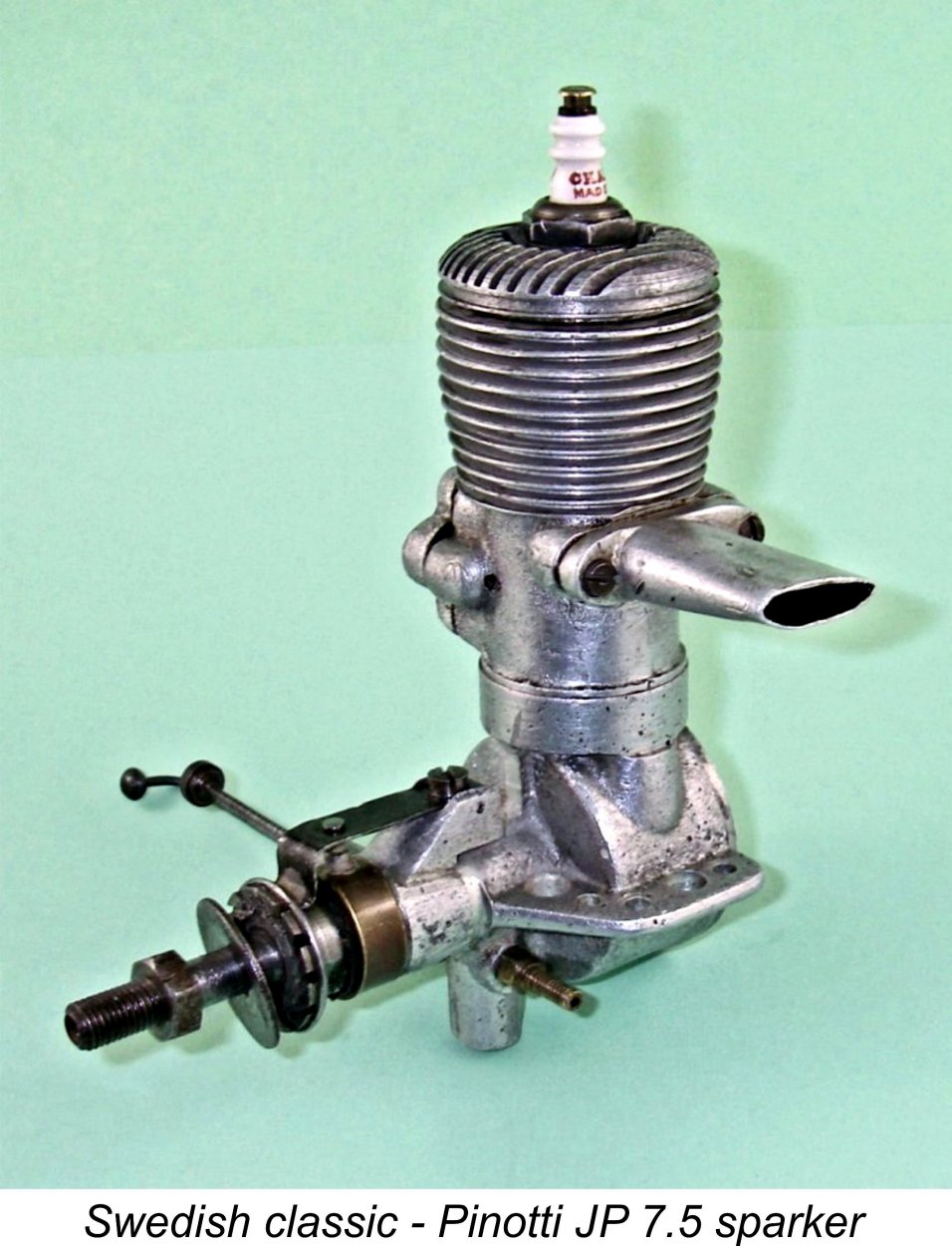 Many of today’s engine collectors – perhaps the majority – own at least a few examples of the old spark ignition units which were effectively the only game in town until the early 1940's, subsequently vying with compression ignition (“diesel”) units for power modelling supremacy prior to late 1947, when Ray Arden changed the game forever with his introduction of the commercial miniature glow-plug. Within a few years of this watershed event, model spark ignition engines had pretty much fallen out of mainstream use, not to return in any numbers until the late 20
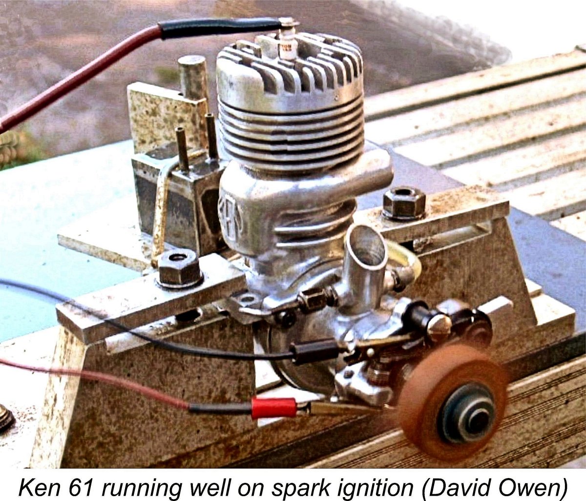
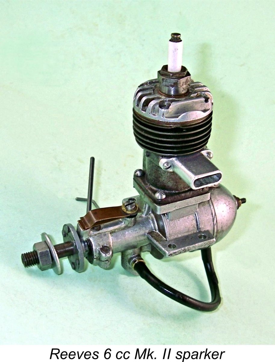 As noted above, classic model spark ignition engines seem to be widely viewed today as anachronisms which are vastly different from latter-day powerplants, presenting near-insurmountable obstacles to their successful operation which modellers of the pioneering era struggled to overcome. It’s this perception which seems to put many people off the idea of trying one out. This being the case, it seems best to start by laying this particular ghost to rest!
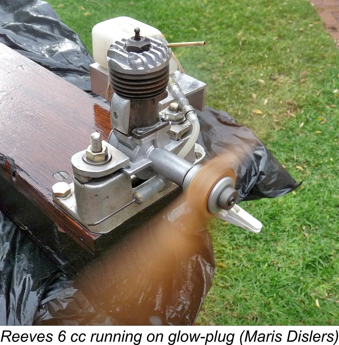 This highlights another of the real advantages of spark ignition operation - flexibility. The ignition timing of a sparker can be very precisely adjusted to suit pretty much any speed. This is a very useful characteristic which the sparker shares with its variable compression diesel counterparts. It allows both sparkers and variable-compression diesels to operate effectively over a far wider range of speeds than glow-plug units, particularly at the bottom end of the speed range.
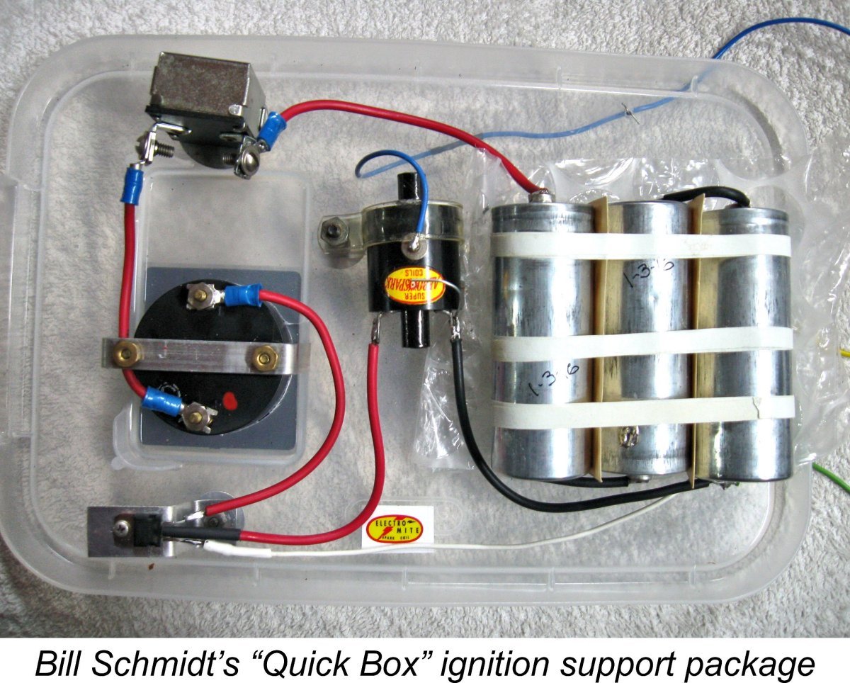
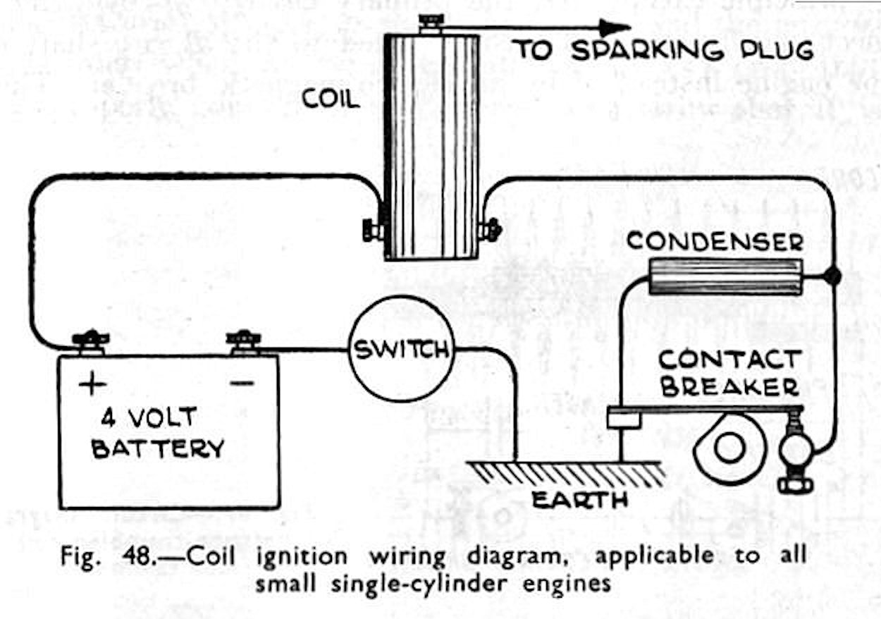 The "classic" circuit used for model spark ignition engines is an adaptation of the one invented by
 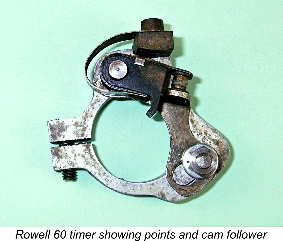 Model spark ignition engines are provided with a set of electrically-conductive "points" (variously referred to as the "contacts", “contact breaker” or "timer assembly”) which are closed by a strong spring and re-opened once per crankshaft revolution (in a two-stroke engine) by a cam attached to the shaft. This cam acts upon an element of the moving point called the cam follower. The sole function of the points is to act as a simple switch controlling the flow of battery current to the primary winding of the coil (see below). Nothing mysterious here - it's just an engine-activated on-off switch!
 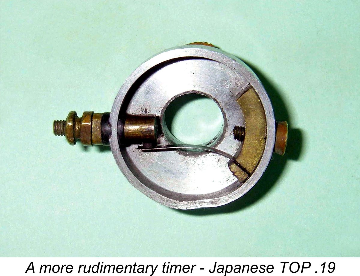 Of course, a very wide point gap is not desirable. The inertia (mass-related resistance to a change in position) of the moving point means that there is always some delay (lag time) in that point responding to the retreat of the cam surface from the cam follower by closing under the action of the spring associated with the moving point. A wider gap will increase the lag time between the withdrawal of the cam surface and the full closure of the points, since the moving point has further to travel under the action of its spring.
 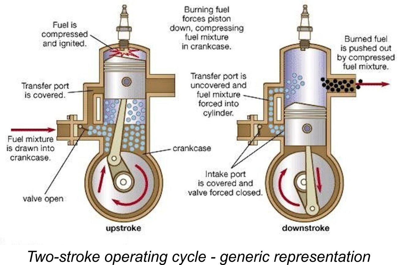 To achieve maximum power, we want the spark to occur at some time before TDC to allow the full build-up of combustion gas pressure in the cylinder by the time the downward power stroke commences. The left-hand image of the attached pairing shows this point very clearly - ignition has occured, but the piston is still rising. The higher the operating speed, the more advanced the optimal ignition timing.
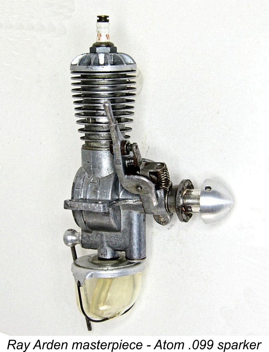
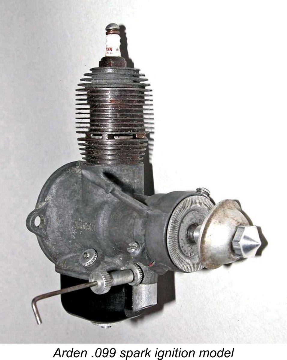
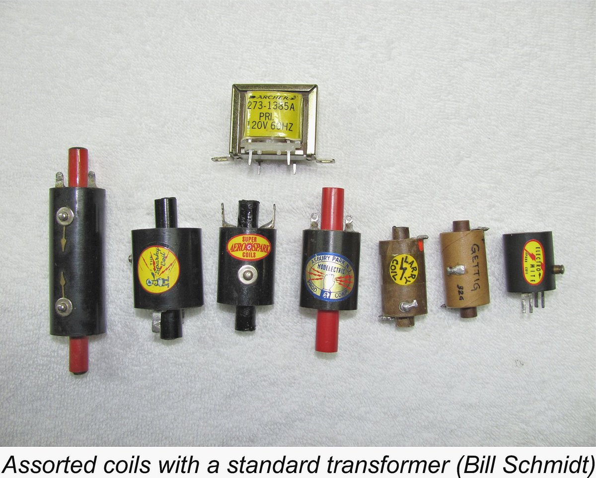 In effect, the coil may quite properly be viewed as a small alternating current transformer. Its basic purpose is to convert the low battery voltage - typically 3 to 4 volts - into a very high voltage which is sufficient to ionize air and cause a spark to jump across an air gap of 0.020 in. or more under several atmospheres of gas pressure in the cylinder. The creation of such a spark requires a voltage (more properly referred to as electrical “tension”) of around 15,000 to 20,000 volts. The current variations and associated induced magnetic field variations are of course produced by the switching on and off of the battery current in the coil's primary winding through the opening and closing of the points.
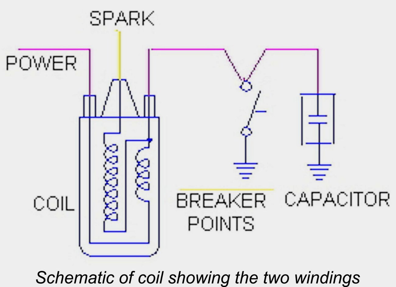 An ignition coil as shown schematically at the left will typically have three connections: a high tension connection which supplies the 20,000 volts to the spark plug; a low tension terminal which is wired to the insulated contact point (and via that, to ground when the points are closed) and carries only the battery voltage; and a battery terminal which is connected to the battery's positive terminal either directly or through the ignition switch. The other battery terminal is connected to ground.
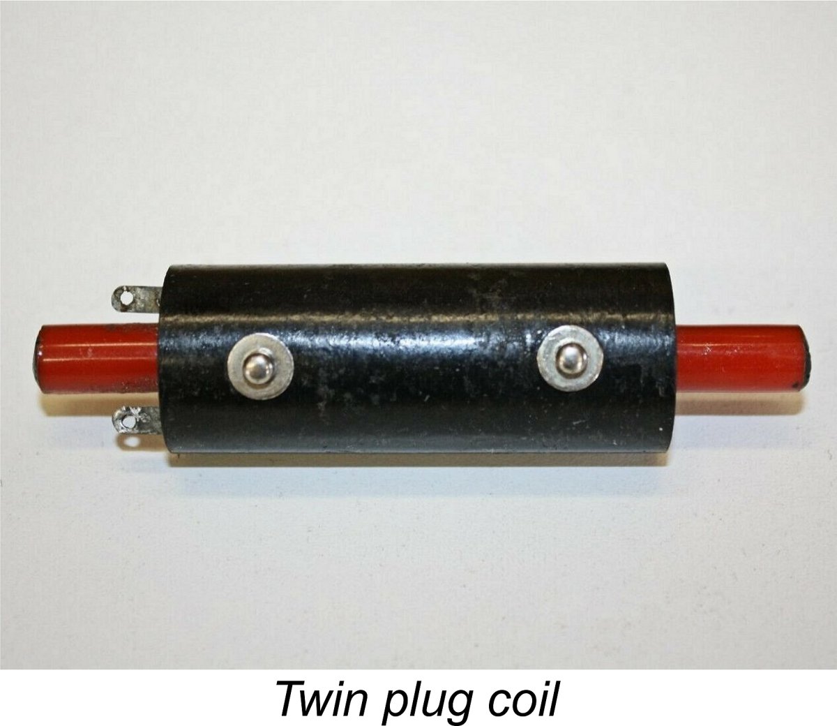
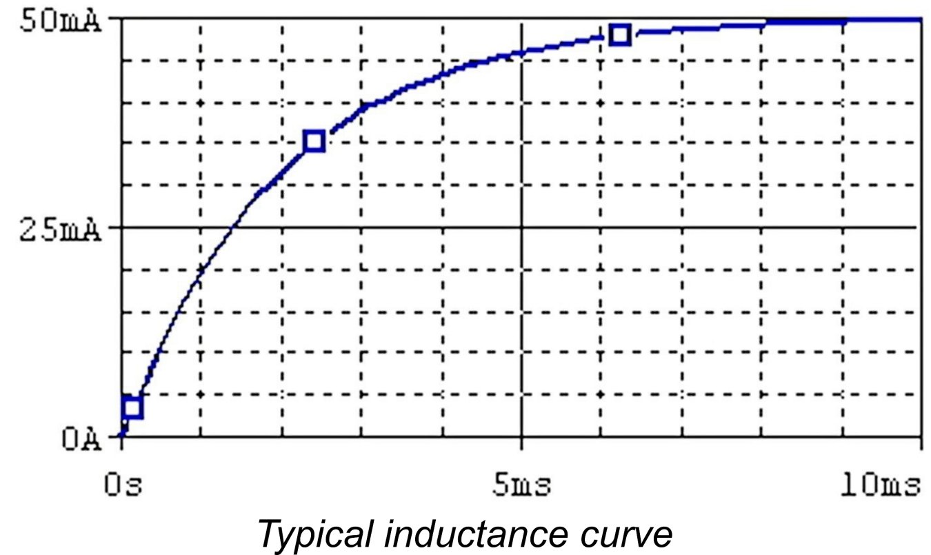 For a given applied voltage, the current approaches the maximum exponentially with time. A typical current versus time curve is shown here as an example, with current in milli-Amps (mA) on the vertical axis and time in milli-seconds (ms) on the horizontal axis. The term “milli” stands for one-thousandth, so a millisecond is one-thousandth of a second. In this example, the voltage applied to the coil is constant but, as can be seen from the graph, the current takes some 4.5 ms to reach 90% of its ultimate stable figure of 50 mA. It actually takes around 10 ms for that maximum to be reached.
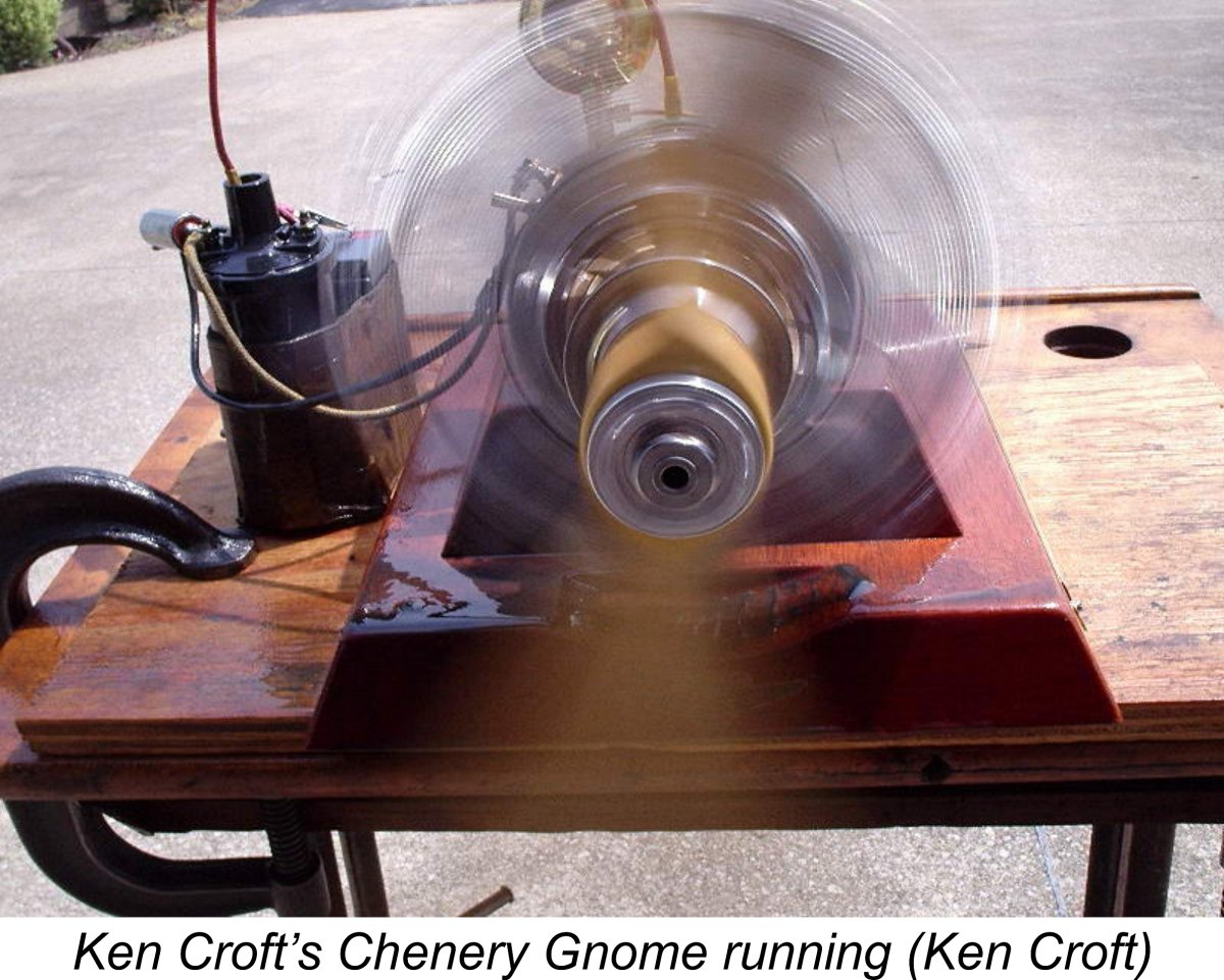 Coils made for model airplane use are necessarily small, to keep weight down. This makes them sensitive to even relatively small departures from their design voltage (and hence current), so for test-running purposes on the bench many model engineers outfit themselves with a motorcycle or automotive coil. This is way too heavy to fly in a model but is reliable and robust, providing a good, hot spark. The accompanying illustration shows Ken Croft’s remarkable Chenery Gnome rotary running nicely with just such a coil supplying the multitudinous sparks.
 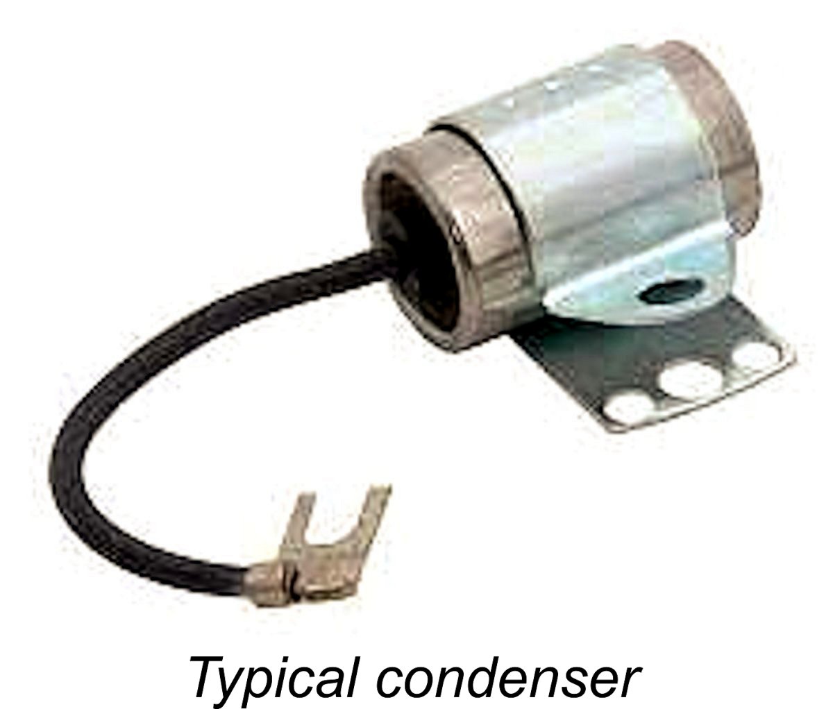 The property in question is measured in Farads (named after the noted British electrical pioneer
 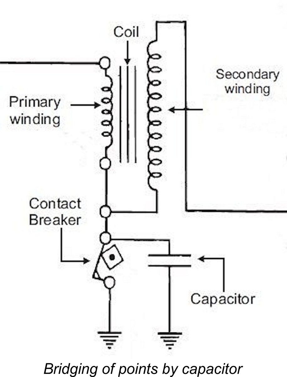 The capacitor is wired so that it effectively bridges the points, as can be seen in the accompanying partial circuit diagram. Its function is to absorb the previously-mentioned self-induced electrical energy which is generated in the primary circuit by the instantaneous collapse of the coil’s electro-magnetic field when the points open and the battery current to the primary coil is consequently switched off instantaneously.
 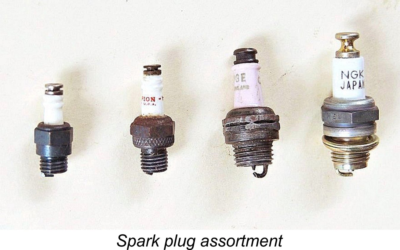 Spark plugs for model use were once as common as dirt. There were still plenty of them about when the glow-plug more or less put them out of business, so vintage examples in good condition remain readily available on eBay and elsewhere. Newly-manufactured plugs are also offered by specialist present-day suppliers. The quality of today’s plugs is actually quite a bit better than that of their ancestors, leading me to recommend the use of a current plug for test running. The Rimfire plugs formerly sold by Larry Davidson are very good indeed.
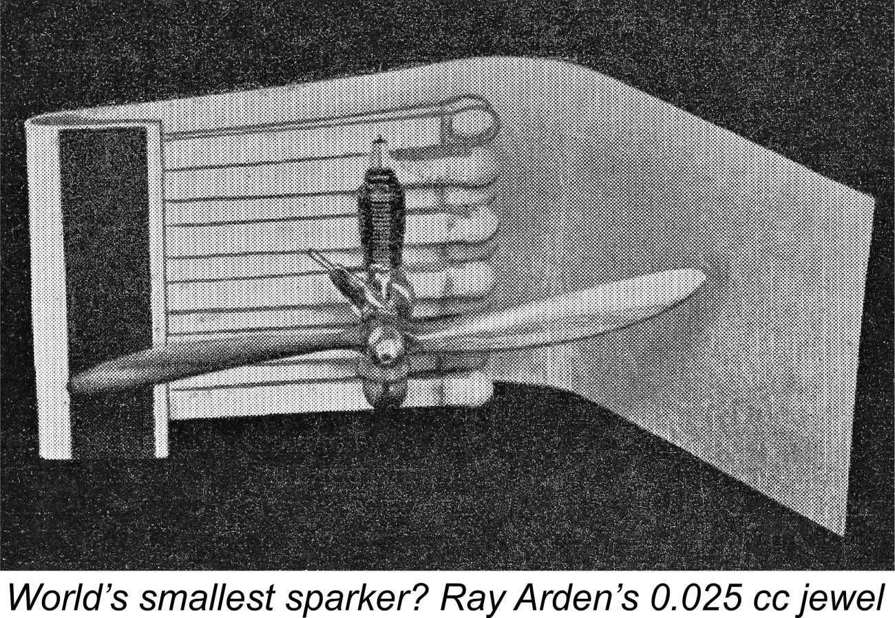
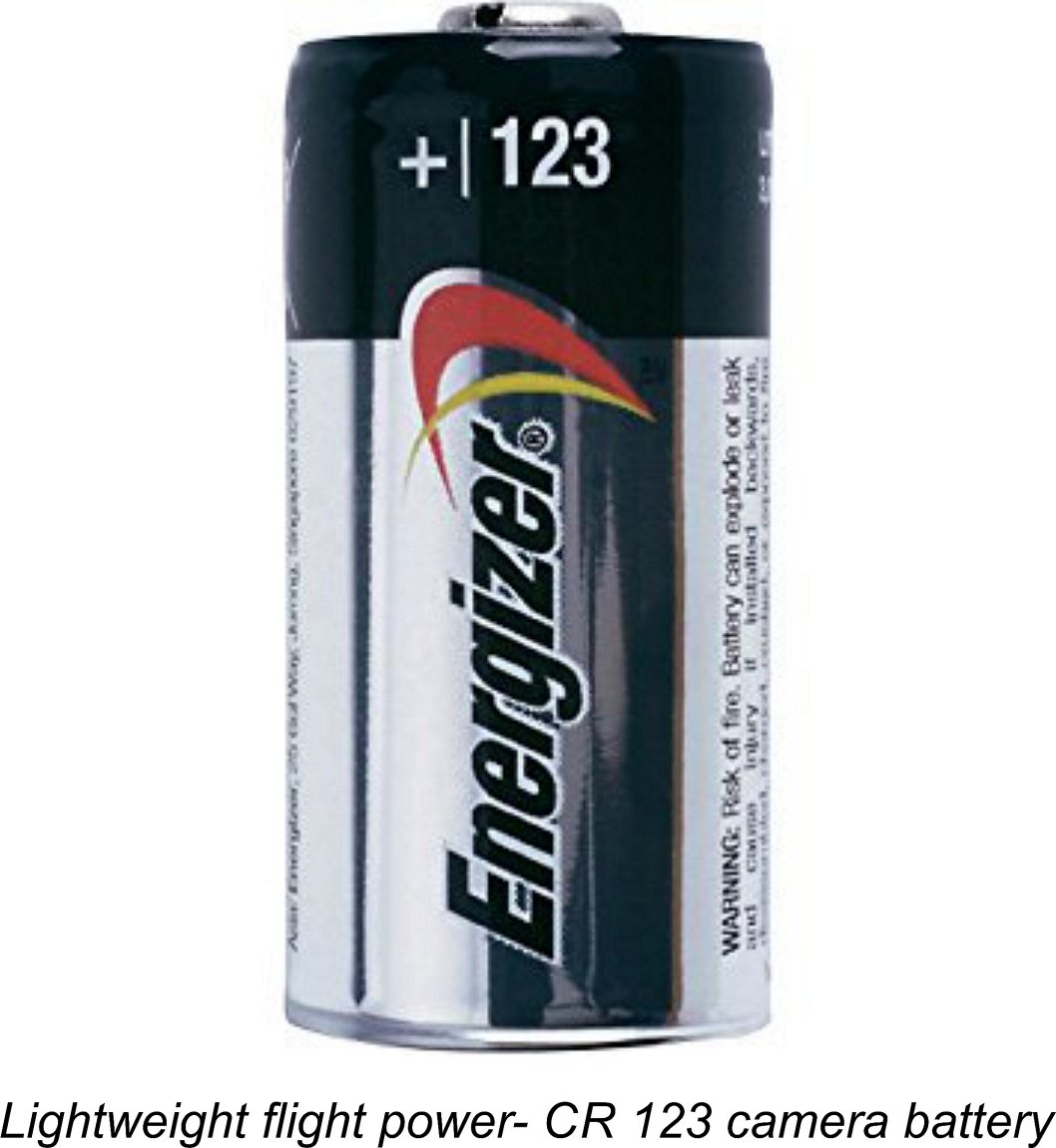 Bill Schmidt advises that he has been successfully using a 3 volt CR123 rechargeable lithium camera battery as a flight unit. Weighing a not-unmanageable 0.60 ounces (17 gm), this has a capacity of 400 mAh (milli-Amp hours). The battery capacity is basically a multiple of the anticipated current draw and the time over which that current can be continuously drawn before the battery is depleted. So a 400 mAh battery can theoretically deliver the expected 4.00 Amps (4,000 milli-Amps) for around 0.1 hours (6 minutes). The fact that the points are only closed for a relatively small fraction of the engine's running time will of course extend this time considerably. Hence the capacity of this battery should be more than ample for flying purposes - in fact, it should be good for a number of flights.
  Of course, if an ignition-interrupting flight timer is included in the system, as it generally would be in a free-flight model, this is not an issue since the timer actually works by opening the primary circuit independently from the points, thus performing the same function as the switch. Such a circuit is shown on the accompanying classic "Gismoe" plan. There are also state-of-the-art ignition systems (see below) which perform the switching function automatically when the engine stops. This would be very useful indeed in applications such as control line in which the engine typically stops by running out of fuel, with the glide-induced torque of the airscrew pushing the piston up against compression in the operating direction in a potentially "points closed" position.
 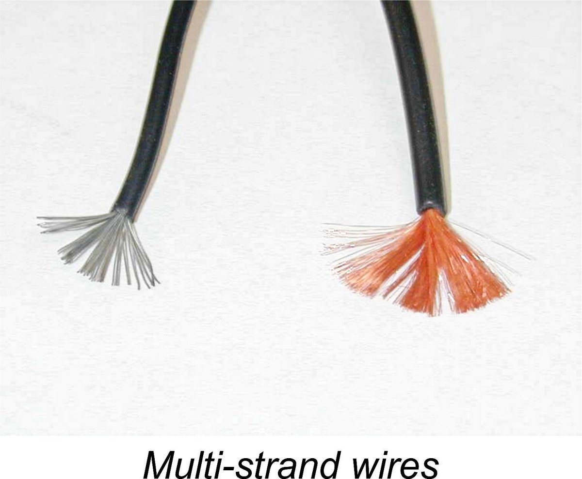 Connecting all the above components requires good quality insulated wire of some form. Today, PVC-covered multi-strand tinned copper wire is generally used. It is going to be exposed to heat and oil, not to mention vibration, so good quality solder joints and top quality wire are called for throughout. Never use unsoldered wrap-around connections! Alligator clips can be used to make the basic engine connections in a bench-testing situation, but they too need to be connected to their wires with high-quality soldered junctions.
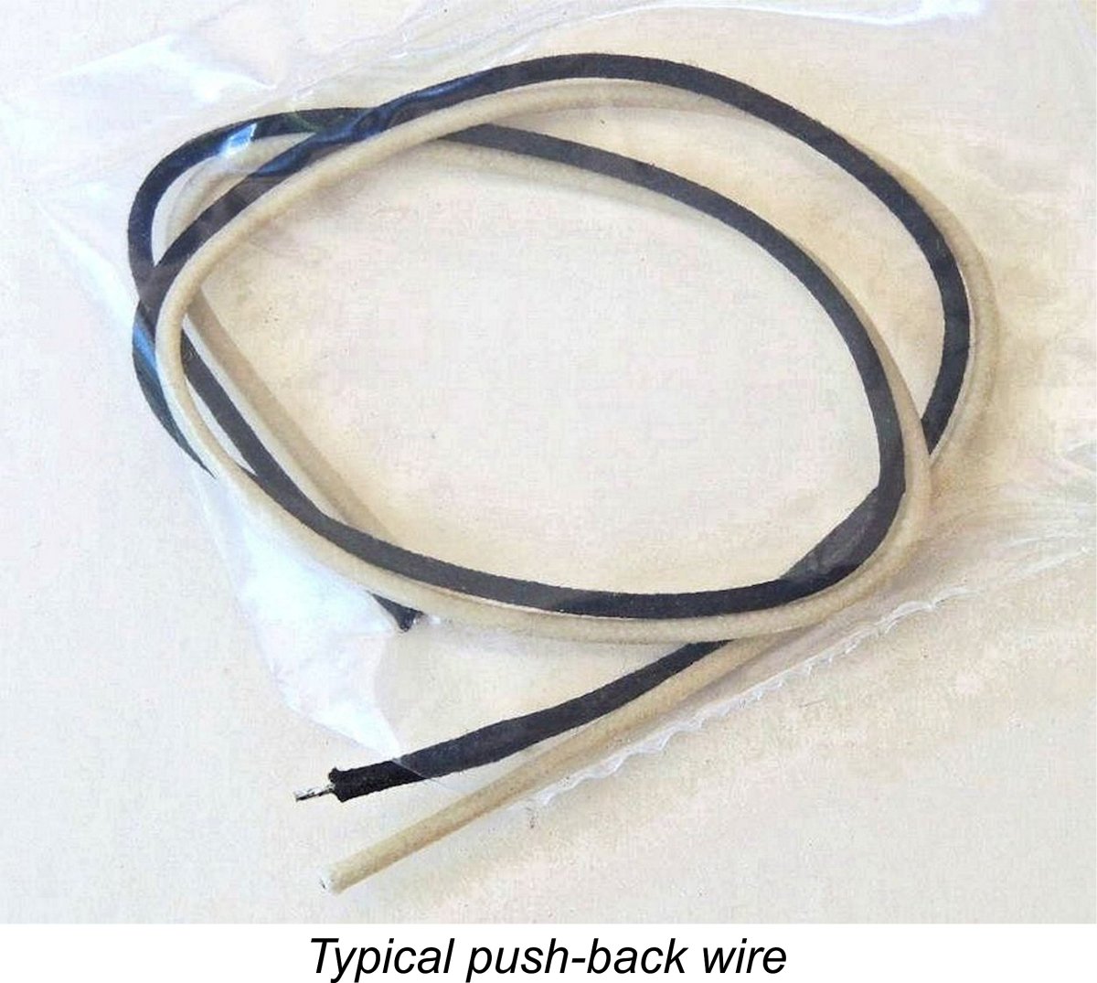
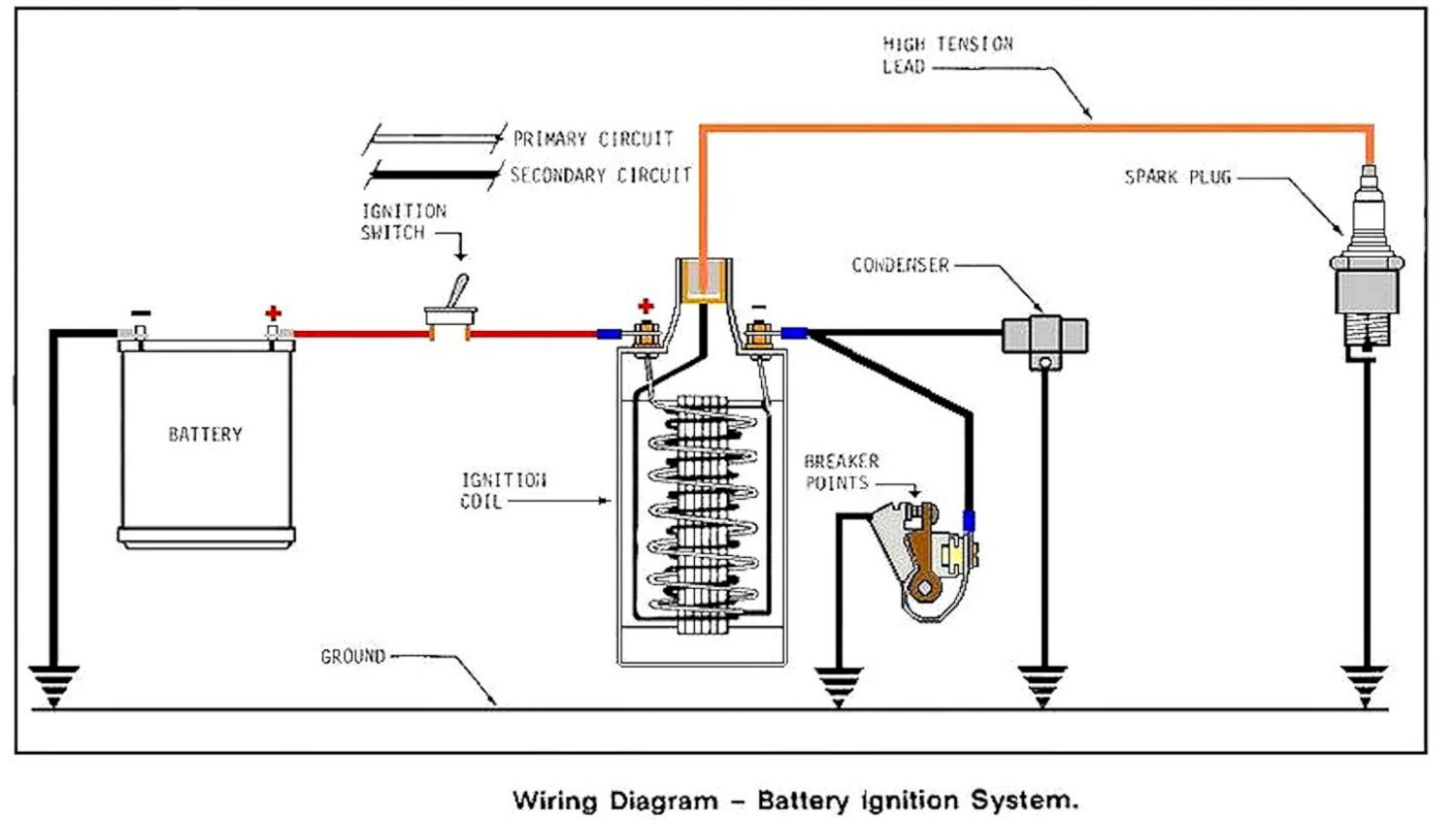
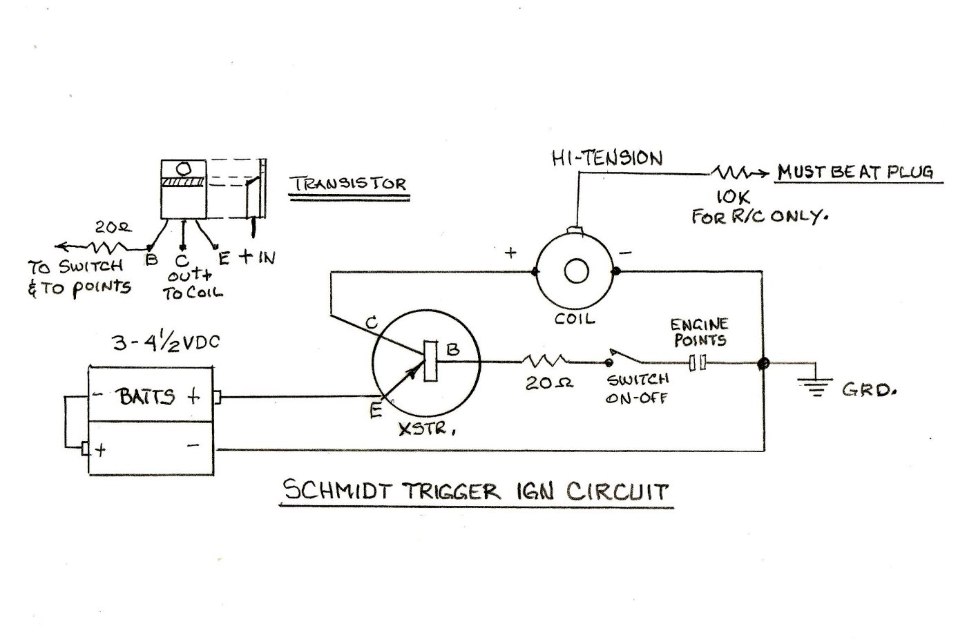
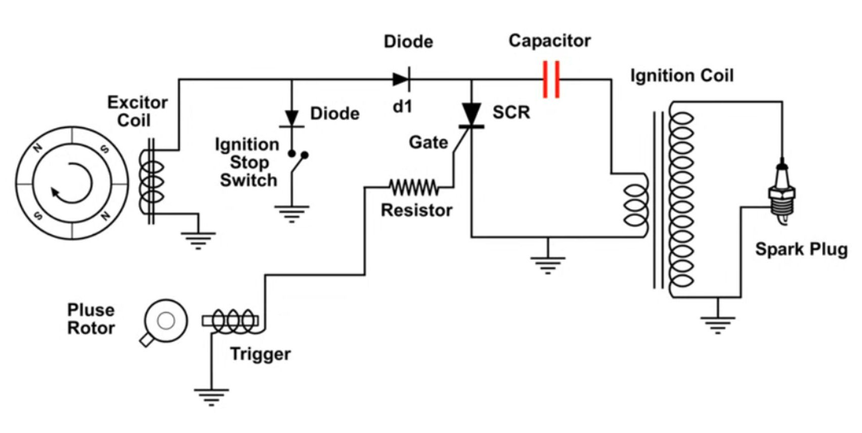
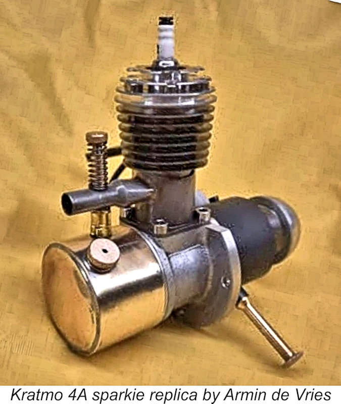
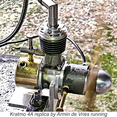 Another sometimes-annoying characteristic of the CDI system that sets it apart from the conventional points-based arrangement is that fact that engines equipped with it can start in reverse! A points 'n cam timer can't do this because if it's set to open (triggering the spark) near Top Dead Centre with the engine being started in the intended direction, if the engine backfires and spins in reverse, everything will happen in reverse - the points will close just after Top Dead Centre (in the reverse direction, remember) and won't open (triggering the spark) until the shaft has turned in reverse through the dwell period - far too late for a start to be achieved.
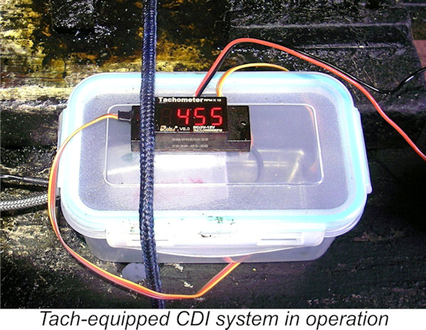
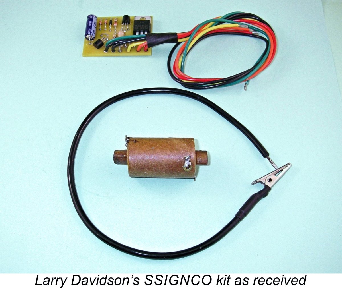 When I first decided to write this article, I accepted at once that doing so would require me to establish some credibility by getting serious about creating my own spark ignition test set-up. To start that ball rolling, my first move was to contact my late valued friend and much-missed colleague Tim Dannels, former publisher of the indispensable “
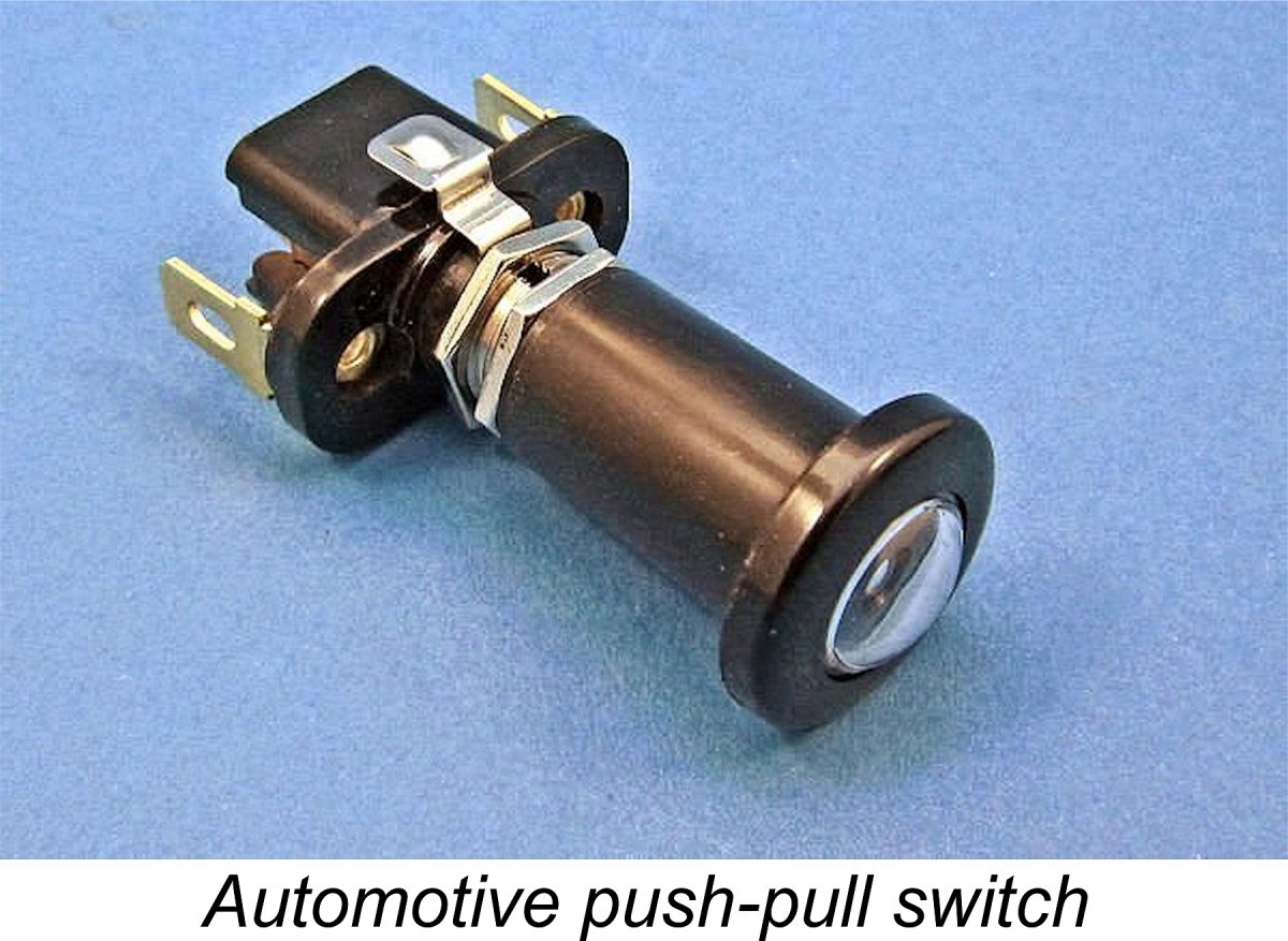 Beginning with the basics, I went to a local automotive parts supplier and bought an automotive pull on/push off switch as recommended by Bill Schmidt. Like many such switches, this was fitted with a small 12 volt light bulb which would confirm that it was in the "on" position when pulled out. Obviously, my lower-voltage power supply would not be sufficient to light the bulb, besides which I didn't need its extra power draw. Fortunately, the bulb is connected in parallel with the main circuit, so removing it doesn't affect the operation of the switch - it simply eliminates the redundant parallel circuit.
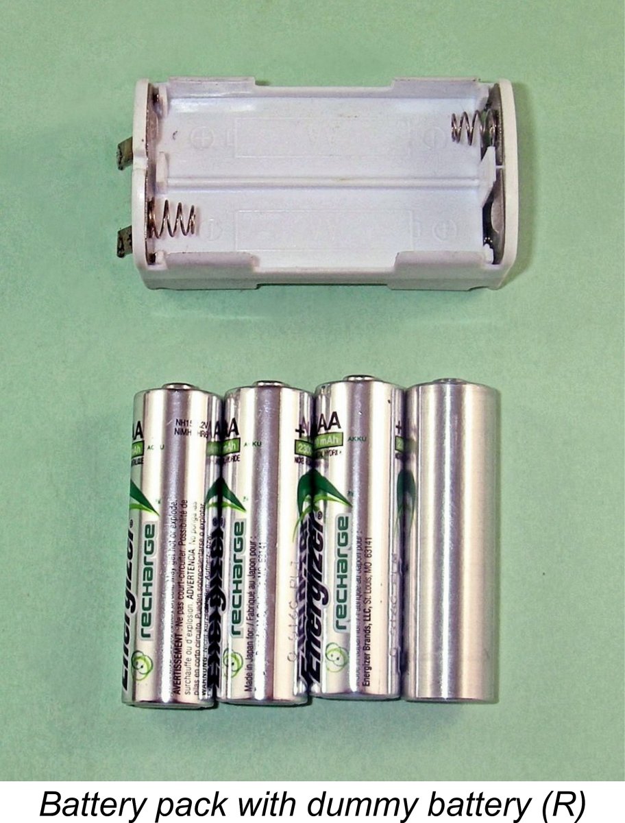
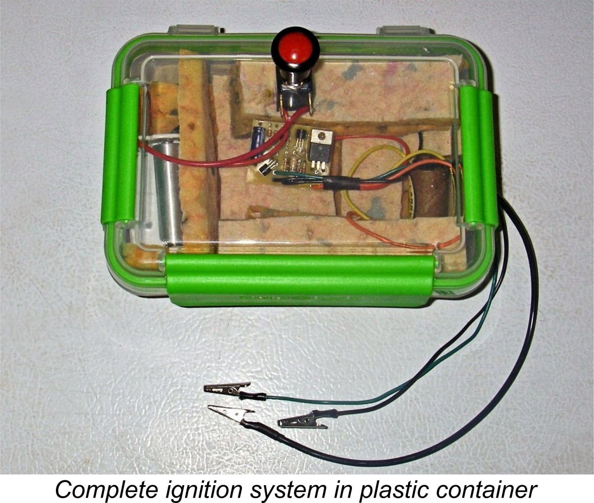
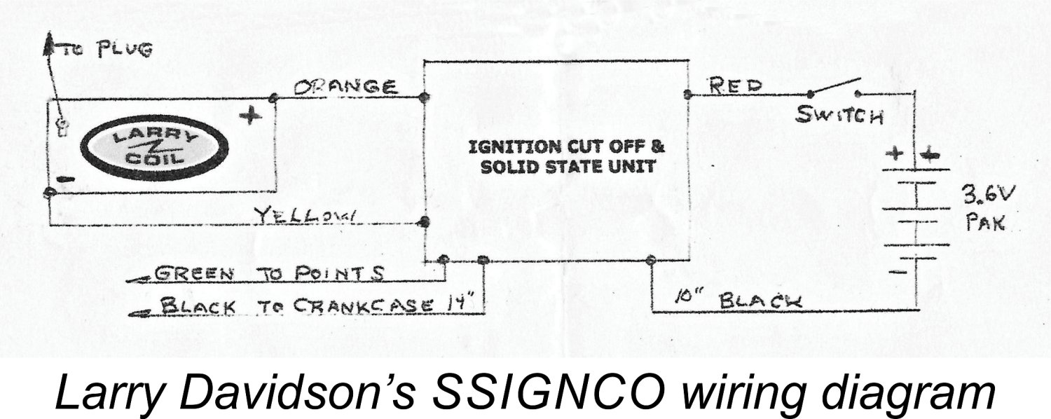
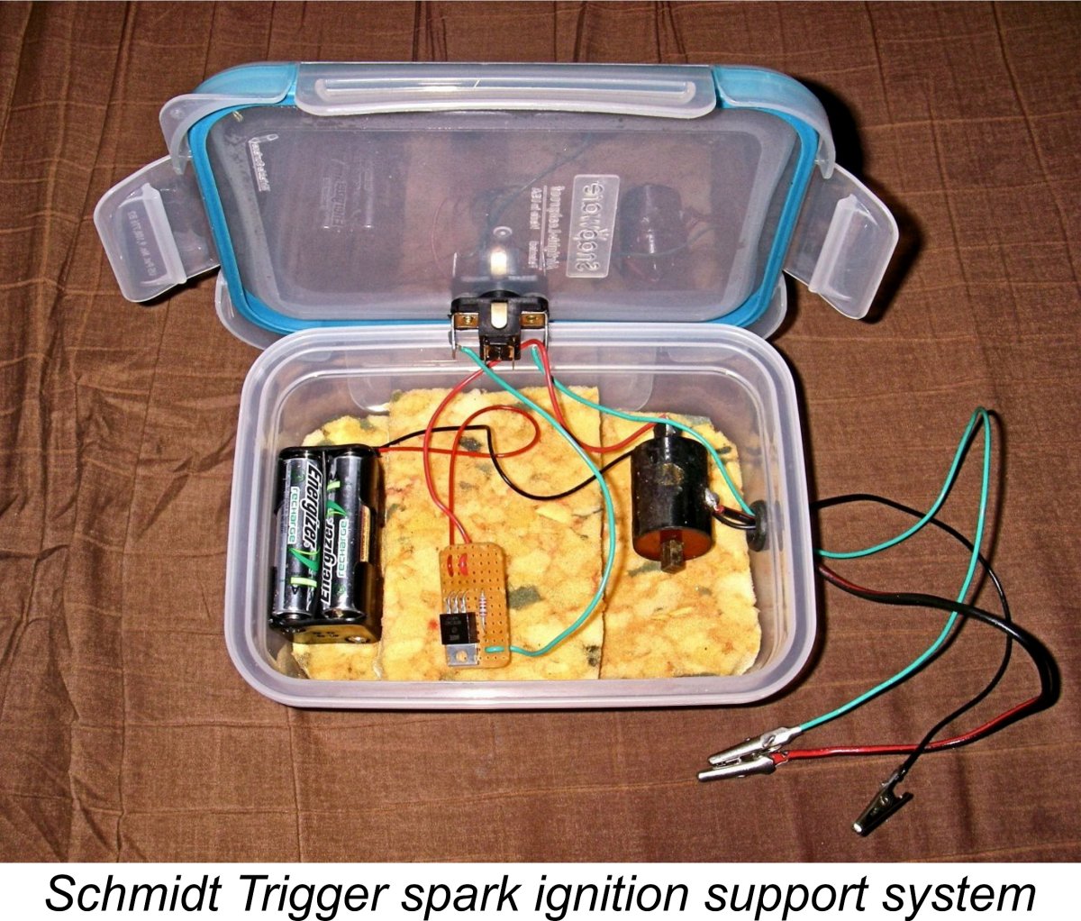 Following the successful completion of the system just described, I decided that I should also check out the original "Schmidt Trigger" system by constructing my own unit based upon Bill Schmidt's original circuit diagram reproduced earlier. Some prospective spark ignition users may wish to save money by adopting this low-cost alternative. I therefore felt that I should check it out myself for the sake of completeness.
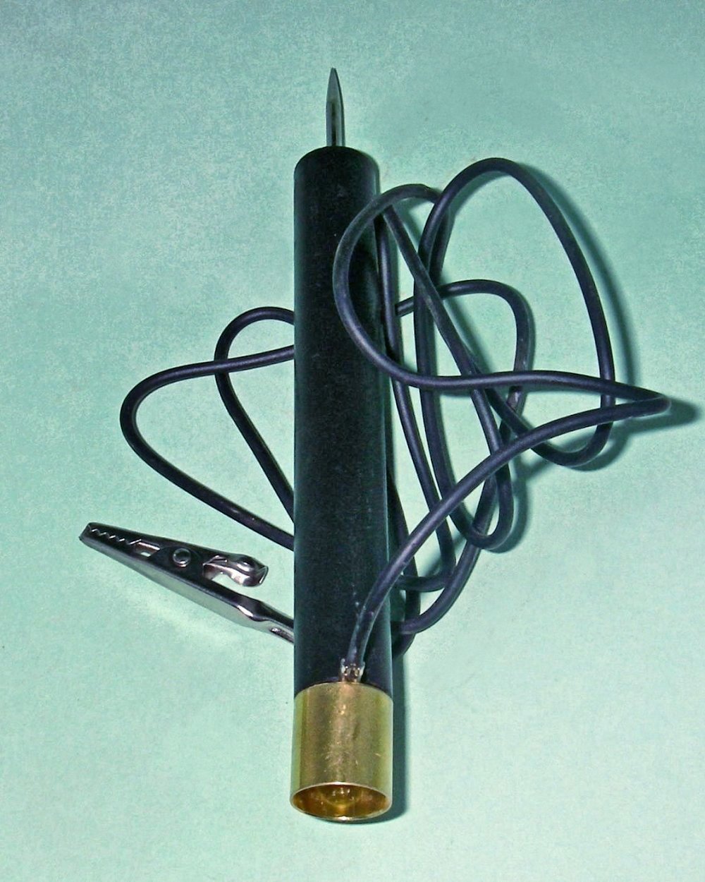 A convenient device for carrying out a timer check is a small battery-powered circuit continuity tester of the type readily and cheaply available at any hardware/electrical store. A typical example is shown at the left. This unit contains two AAA batteries and a 3 volt light bulb which is exposed at one end. The other end is equipped with a pointed metal probe. A wire with an alligator clip at its far end is connected to the opposite pole of the light bulb. When the alligator clip is electrically connec
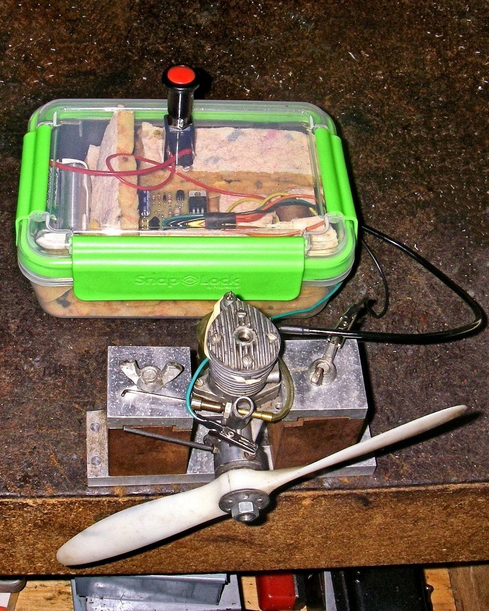
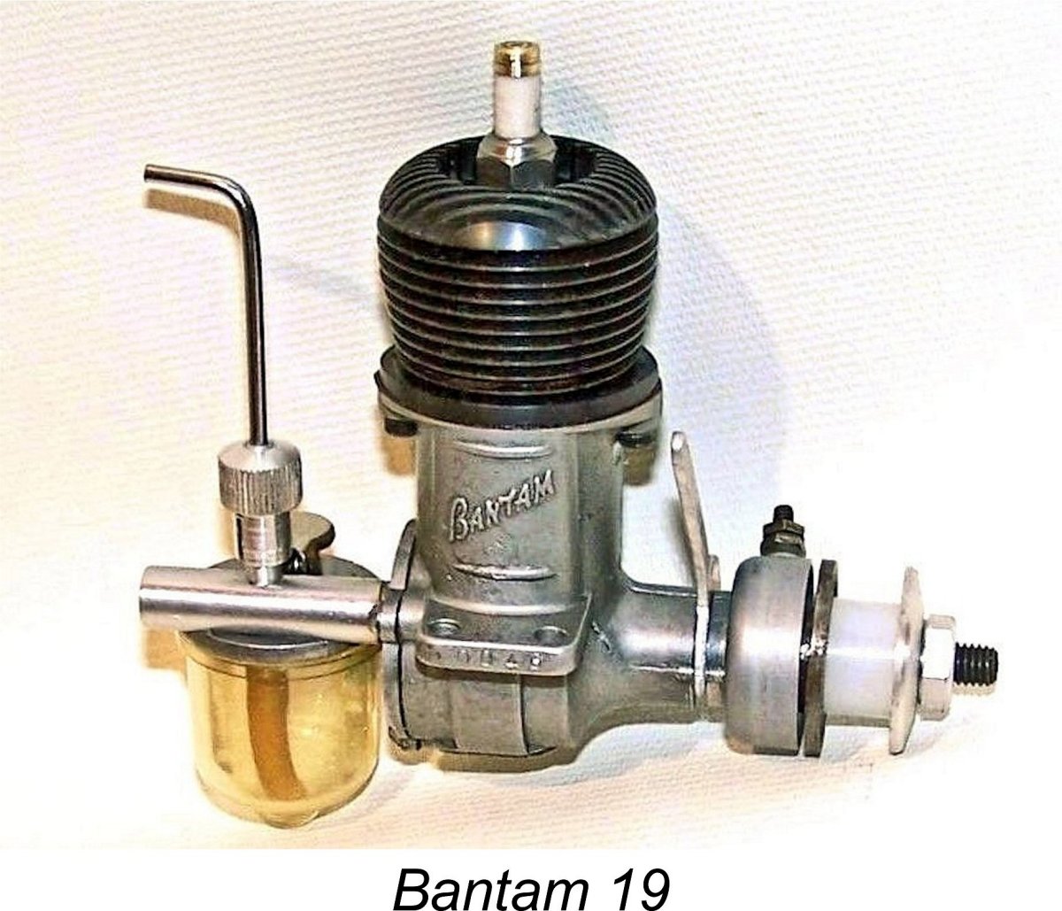
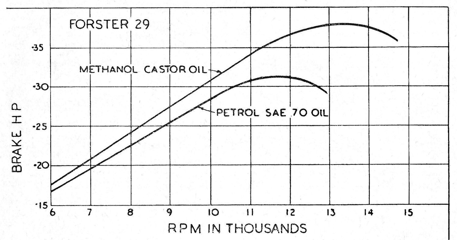
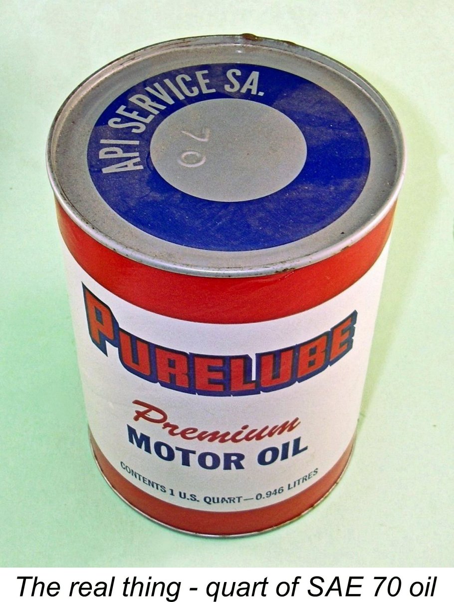 Turning now to the lubricant in the fuel, the general recommendation way back then was of the order of 3 parts gasoline to 1 part of heavyweight mineral oil (unblended castor oil doesn't mix with gasoline). The usual oil recommendation was SAE 70, but that's no longer readily obtainable. Fortunately, there are present-day alternatives which seem to work just as well. Both Maris Dislers and I have used SAE 50 Harley Davidson motorycle oil in both sparkers and classic sideport diesels with complete satisfaction. An available alternative that is closer to the old-time recommendation is AeroShell 120, which is an aircraft-grade mineral oil having a viscosity of SAE 60. It seems to work well. Multi-grade oils need not apply - the dilution factor greatly affects their performance in a two-stroke engine.
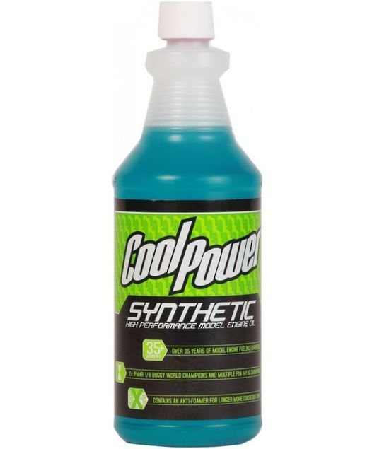
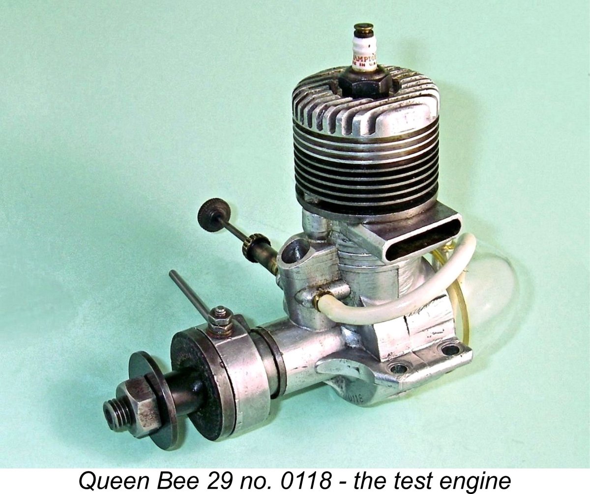 As my first test subject for my two new ignition systems, I elected to try a used but still highly servicable example (engine no. 0118) of the relatively rare 1946 Queen Bee 29 sparker from Vancouver, British Columbia, only a few kilometres from my present-day home in Coquitlam. A test of this engine was very timely since I had just completed a detailed article covering the history of the
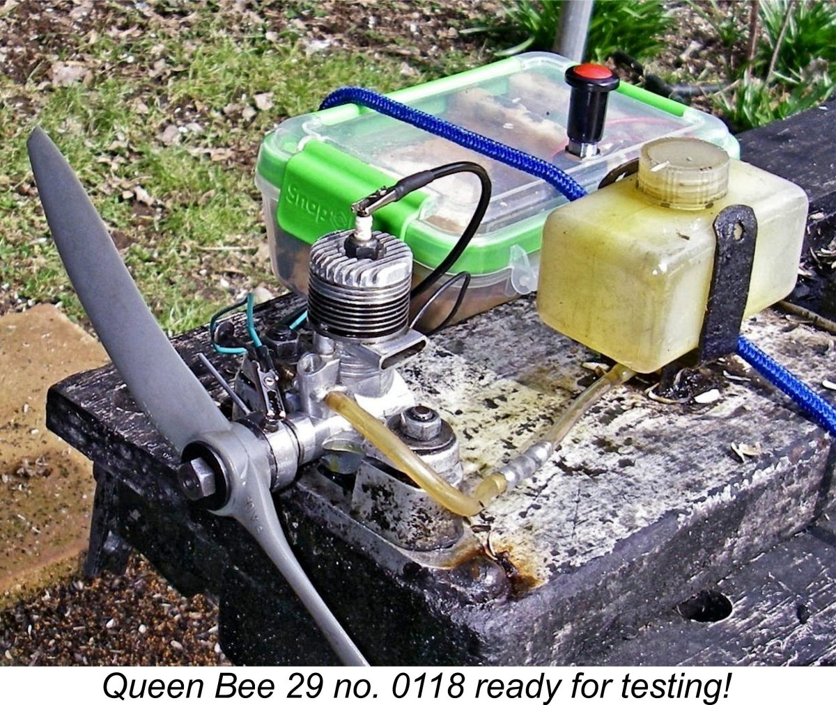
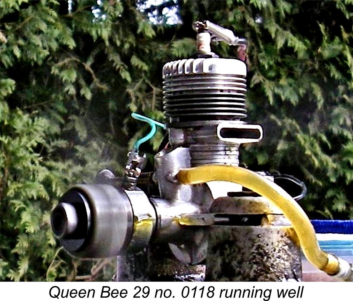 I have to say that both the engine and its spark ignition system lived up to their respective reputations - the engine fired on both the first and second flicks and started on the third! Can't ask for much better than that! Once running, the Queen Bee settled into a nice smooth 'n smoky four-stroke operating mode, waiting patiently for me to set it for best performance. Just like an over-rich glow-plug motor, in fact. I had all the time in the world to take stock.
 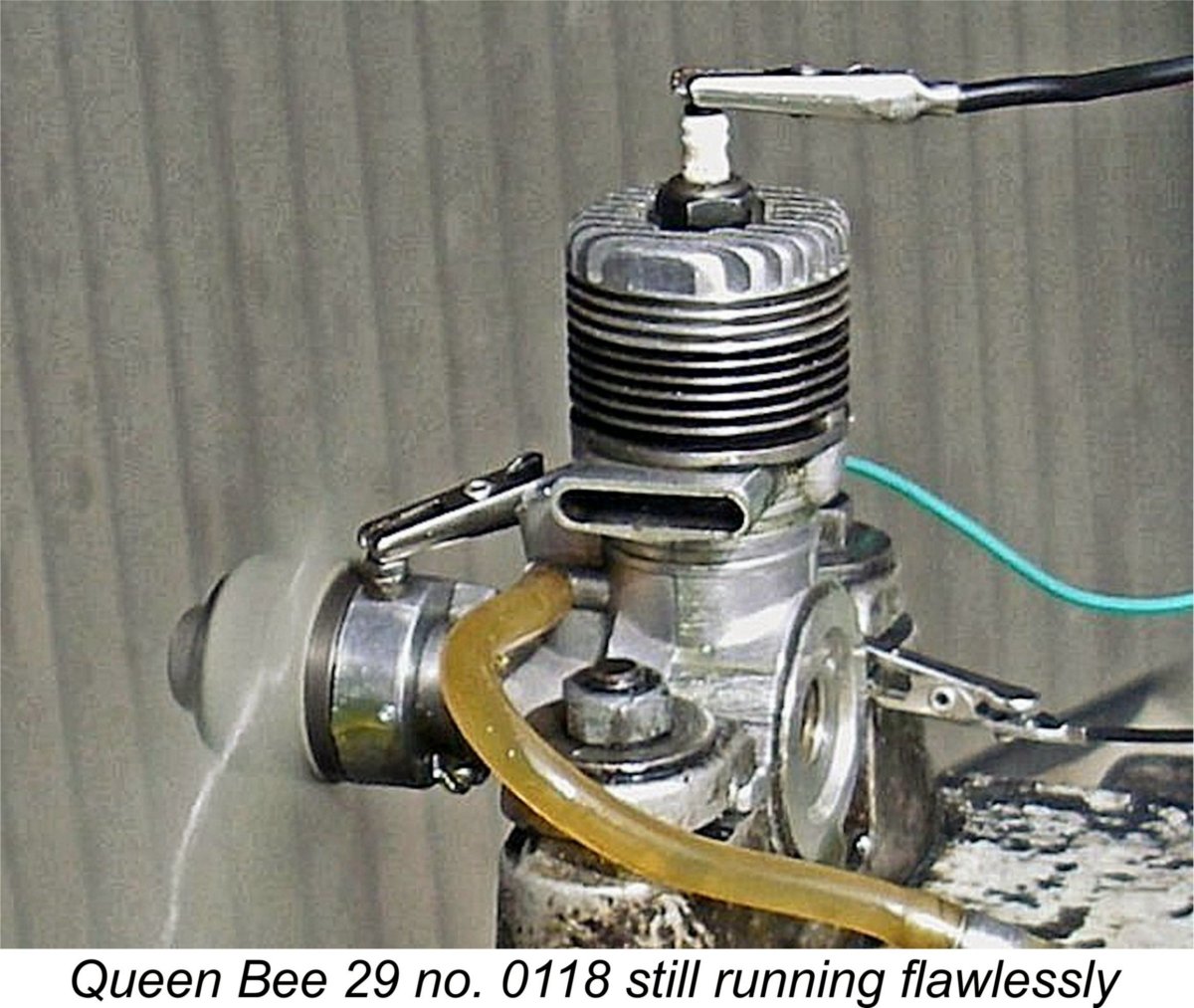 The engine ran the tank out cleanly, with no signs of distress at any time. After allowing it to cool down, I tried a re-start, which was just as easy as the first attempt. I took a little more care over the final settings this time, getting the APC 10x6 prop turning at 8,600 rpm with very smooth running. Clearly the timer is still functioning well at this speed despite its relatively short dwell period. The implied power output was around 0.240 BHP - by no means a dismal figure for an engine of this specification and vintage. However, it seems likely that the Queen Bee was approaching its peak on this prop using the white gas fuel.
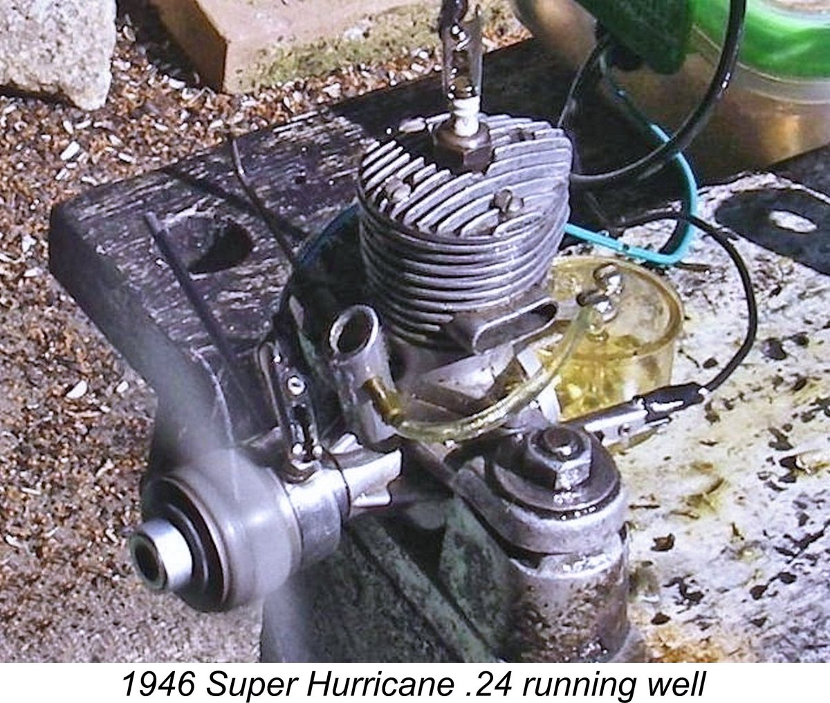
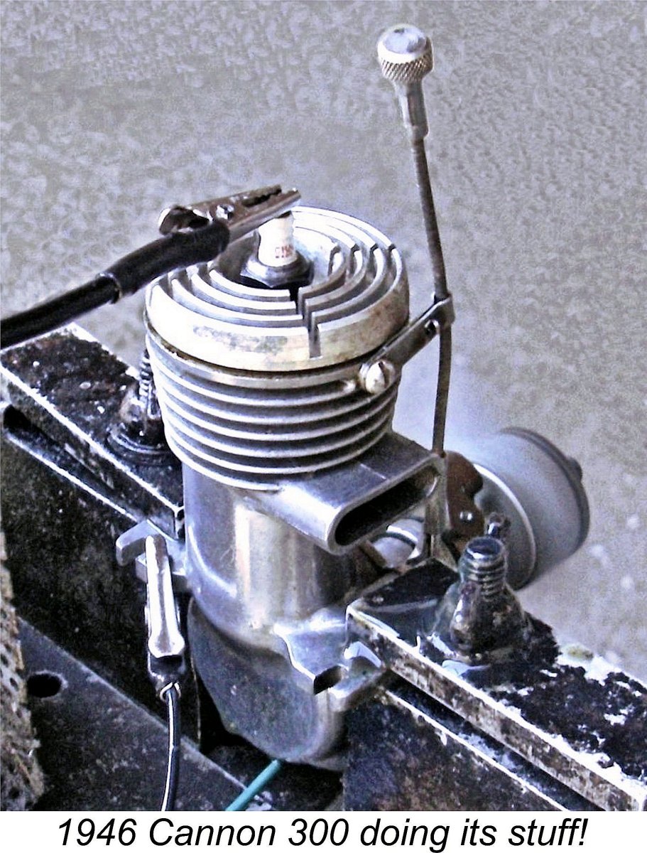
| |