
|
|
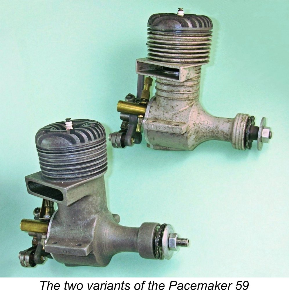
Class C Classic - the Pacemaker 59
In truth, I see extreme rarity on its own more as an argument against the investment of time in covering a given engine, because very few people will ever be able to experience such engines for themselves, making commentaries on them far less practically relevant. People want to know about what they have or may aspire to have, not what they will probably never have! Accordingly, it’s actually far more relevant and hence important to cover the more common ranges, examples of which may very well end up in the hands of many of my fellow collectors. Another powerful motivation is the technical originality displayed in a particular design. I’ve always been attracted to engines which display a degree of design originality. The central subject of this article, the 1946 Pacemaker 59 sparkie from New York, certainly falls very much into that category.
It thus came as something of a surprise to me to learn from Tim himself that the Pacemaker 59 is one of the relatively few commercial American engines which was never the subject of a focused article in ECJ! Tim’s previous coverage of this engine was confined to a couple of brief entries in AMEE. This identified an information gap which I saw as being well worth filling. This provided the primary motivation for developing the present article. I hasten to add that it was undertaken with Tim’s full knowledge, blessing and material assistance! With that as my justification, I’ll get right into summarizing such information about this interesting engine as can be shared authoritatively with my valued readers. Here goes ………….. The Pacemaker 59 - Historical Overview
The Pacemaker 59 was first advertised in the pages of “Model Airplane News” (MAN) in March 1946 at a price of $24.95, subsequently being included in Edward G. Ingram’s article entitled “Recent Model Engines” which appeared in the June 1946 issue of MAN. Ed Ingram was MAN's regular writer on model engines during the latter half of the 1940's, hence being more or less an American counterpart of Lawrence H. Sparey or Peter Chinn in Britain. Ingram's June 1946 entry for the Pacemaker read as follows: “Details of the Class C Pacemaker have just been disclosed and are included in the table. The cylinder and crankcase are cast in a compact unit of magnesium alloy and the crankshaft is mounted on ball bearings. A detachable aluminium alloy cylinder head is provided. A very thick Meehanite iron cylinder prevents the possibility of distortion from heat. The cylinder bore is 0.930 in., the stroke 0.875 in. and the piston displacement 0.594 cuin.”
A number of earlier passing references have placed Bill Siedler’s manufacturing activities in Brooklyn, New York. However, the Pacemaker was introduced under the auspices of the Capitol Manufacturing Co. Inc. of New York City. The sole advertisement from this company was that first-ever placement in the March 1946 issue of MAN, as reproduced here at the right. The New York City address wouldn't necessarily rule out a Brooklyn location for the actual manufacturing - it might reasonably be supposed that the engines could have been produced at an unknown address in Brooklyn and marketed from the New York City location. However, that March advertisement appears to confirm beyond argument that the Pacemaker engines were actually manufactured To me, this looks as if Bill Siedler had set up his manufacturing operation at Mott Street and reached an agreement with the Capitol Manufacturing Co. of nearby Centre Street to market the engines. If this was what happened, the arrangement didn't last long. The advertisement (left) which appeared in the following month's April 1946 issue of MAN was placed in the name of a company calling itself Pacemaker Engines Inc. of 199 Mott Street, New York The same advertisement appeared again in the May 1946 issue of MAN. However, advertisements in MAN appear to end at that point, with the promotional effort being re-directed towards the rival "Air Trails" magazine. The only advertisements from that publication that I've been able to find so far are those which appeared in the issues of June 1946 (right) and August 1946 (below left). Both were expensive-looking multi-coloured placements. The August 1946 advertisement shown below at the left occupied the entire rear cover of the August 1946 issue of "Air Trails" magazine. Thanks to David Burke for providing this scan! A close review of these advertisements brings up an interesting side-issue which merits discussion here. Many model engine ads from the period (not only those for the Pacemaker) cited an address which included a Department number. Many people have wondered why such relatively small and narrowly-focused companies required sub-division into Departments in this way.
The Pacemaker advertisements placed in MAN used the M designation for the Department, while those from "Air Trails" employed the letter A. The number which followed the publication indicator corresponded to the month of the issue in which that advertisement appeared. Thus an inquiry directed to Department M-4 resulted from the prospective customer having responded to the advertisement in the April 1946 issue of MAN. If directed to Department A-6, the inquiry resulted from the customer responding to the advertisement which appeared in the June 1946 issue of "Air Trails". This system allowed Pacemaker Engines to monitor the effectiveness of their advertisements placed in different publications from month to month. The Departmental designation B appeared on the box and the literature which it contained. An inquiry bearing this Departmental designation would indicate that the prospective customer got the address from an examination of the packaging and literature which accompanied the engine. For obvious reasons, no month designation could be included in such cases. These advertisements highlight another noteworthy point. All of them are full-page placements featuring quite expensive-looking coloured artwork. Moreover, the artwork seems to have changed more or less from month to month. Taken together, these characteristics imply a substantial ongoing promotional budget. It's clear that Bill Siedler promoted the engine quite vigorously, at least during the first six months of its manufacturing lifetime.
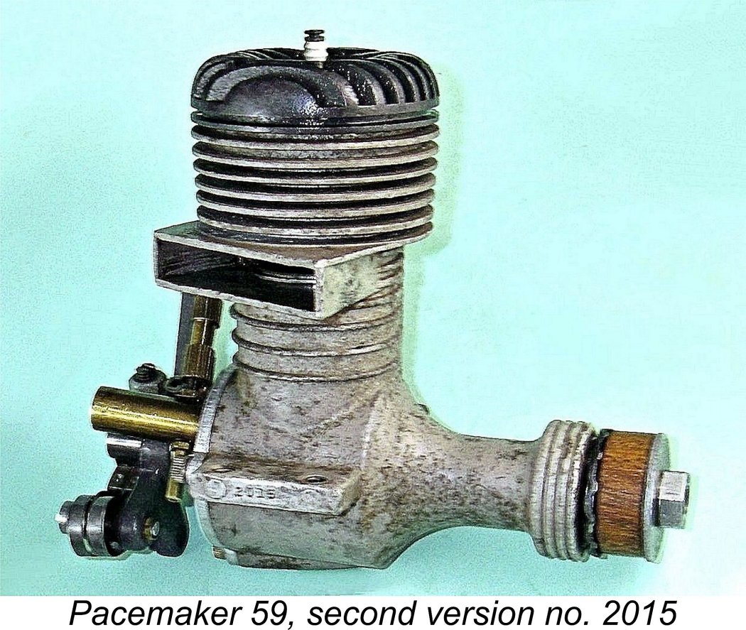
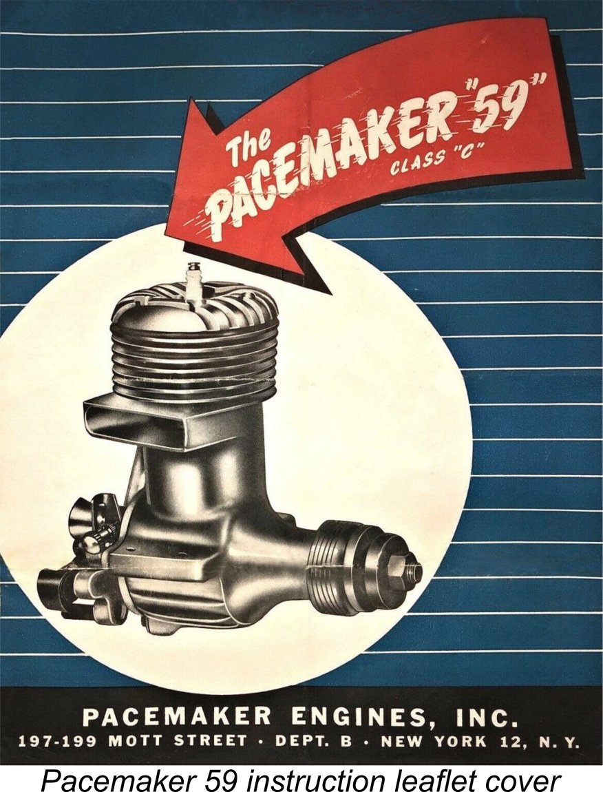
It appears that this advertising effort paid off - the initial response to the Pacemaker was sufficiently encouraging that plans were soon made to increase production. This involved a switch from sand-castings to die-castings for the main crankcase, still magnesium-based. The new casting featured ribs around the cylinder below the exhaust stack as well as ribs around the front ball race housing. The surface treatment of the casting alloy was also changed, resulting in a lighter coloration of the die-cast cases. Oddly enough, it would seem that the die-cast version of the engine was never advertised despite the indications from reported serial numbers that it was made in significantly larger numbers than the original sand-cast variant. The Pacemaker was sold with a 60-day warranty provided that the guarantee card supplied with the engines was promptly returned to the manufacturer. A strikingly-decorated folding instruction leaflet was also included.
The engine evidently continued to be well received - reported serial numbers appear to confirm that the number manufactured went well over the 2,500 unit mark during the year or so during which the engine evidently remained in production. The Pacemaker was listed once again in the tables forming part of Ed Ingram’s article entitled “Model Motor Symposium” which appeared in the December 1946 issue of MAN. However, no text was included - Ingram clearly felt that his earlier June 1946 comments remained sufficient when taken together with the information in the tables.
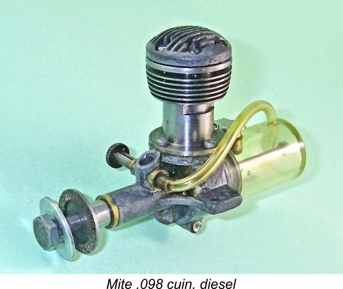
The trigger was pulled in 1946 by Howard Manderville, who designed an innovative .099 cuin. fixed-compression diesel called the Mite. A detailed article about the Mite .099 diesel appears elsewhere on this website. Seeking a manufacturer for his design, Manderville approached Walt Schroeder, one of the true pioneers of the model airplane industry who was a former partner of Ben Shereshaw and a future Editor of MAN. At the time in question, Schroeder owned an operation called the Eagle Manufacturing Company of Brooklyn, New York. The primary business of this company was kit manufacture, but Schroeder nonetheless agreed take on the production of the Mite diesel. However, he needed experienced help to do so.
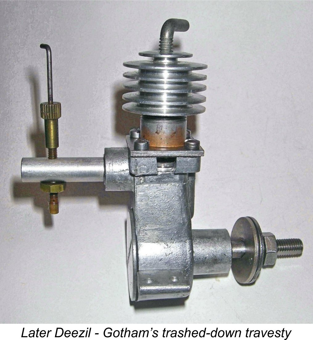
Regardless, Bill brought a wealth of machining and model engine production know-how to the Mite venture, which enjoyed considerable success prior to the complete take-over of the American power modelling scene by Ray Arden’s glow-plug beginning in late 1947. More of that story elsewhere. Returning to the Pacemaker, Bill Siedler had too much invested in that project to simply walk away from it. He looked around for a buyer and was unfortunately successful in finding one in the shape of Gotham Hobby of 107 E. 126th Street in New York City, who assumed ownership of the Pacemaker project in mid 1947.
It thus seems likely that Gotham merely took over the rights and residue of the project, marketing any complete engines which could be assembled from the acquired material. This impression is reinforced by the fact that they offered fully assembled examples at a bargain price of only $12.50. In 1948 they muddied the waters even further by advertising the engine in kit form for only $7.50. The advertisement which is reproduced below at the left was run three times by Gotham during 1948.
For whatever reason, the evidence strongly suggests that production of the Pacemaker ended at some point during early to mid 1947. It’s probable that without Bill Siedler’s enthusiasm and expertise, continued production wasn’t feasible. Whatever the reason, by late 1947 Ed Ingram had clearly become aware that the Pacemaker was no longer in production, since the engine was omitted from both the text and associated tables included in his article entitled “Model Motors for 1948” which appeared in the January 1948 issue of MAN. He apparently discounted the Gotham Hobby offerings - that company's reputation clearly preceded it, even at this early stage! The Pacemaker 59 thus seems to have enjoyed a production period of perhaps a year at most. Did it deserve such a sorry fate? Let’s find out, beginning with a description of the engine. The Pacemaker 59 - Description
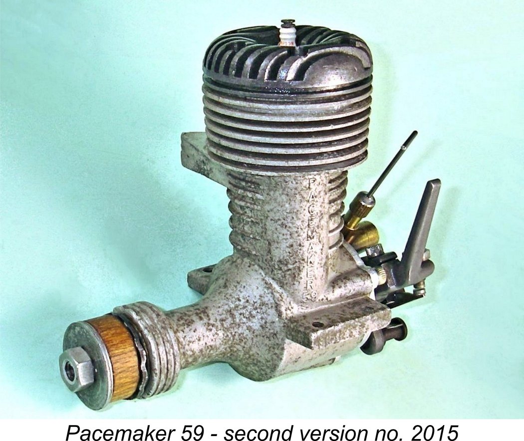
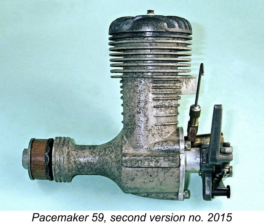
Beginning with the tale of the tape, the Pacemaker sports bore and stroke measurements of 0.930 in. (23.62 mm) and 0.875 in. (22.23 mm) respectively for a displacement of 0.594 cuin. (9.73 cc). An engine intended for all-out performance applications would undoubtedly take full advantage of the class displacement limits. The engine reportedly weighed in at only 13 ounces (with plug and timer) - unusually light for a twin ball-race engine of this displacement. The use of magnesium castings doubtless contributed to this low figure. That said, my own illustrated second model example no. 2015 weighs in at a checked 14.25 ounces (404 gm). I have no explanation for the discrepancy. Even so, this is still relatively light for a twin ball-race sparkie of this displacement.
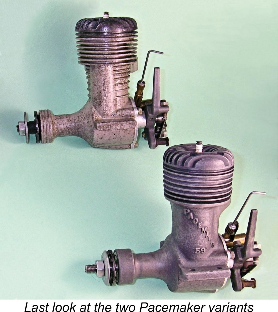
The head is attached to the cylinder barrel by six 6-32 Allen-head screws - a quality touch. A matching Allen wrench was included with each motor. The manufacturers cited a compression ratio of 10 to 1. My example actually checks out at exactly this relatively high figure, and it certainly feels like it when flicked over! The engine is built up around a main casting formed in magnesium alloy which incorporates the cylinder barrel, cooling fins, bypass bulge, exhaust stack, beam mounting lugs and main bearing housing in a single unit. The earliest examples featured a sand-cast case bearing the Pacemaker name cast diagonally in relief onto the bypass, while later units progressed to a die-cast component with the name cast vertically.
It has often been stated that the two case styles were formed from different alloys, but the reality appears to be that the alloy remained the same - only the surface treatment changed. The die-cast cases undoubtedly display a lighter coloration externally, but this evidently arises from the fact that the die-cast cases were given some kind of corrosion-resistant surface treatment which imparted a lighter coloration with just a hint of yellow in it. The untreated interior surfaces retain the dark blue/grey colour of the untreated magnesium alloy - check the view of the crankcase interior which appears below.
One of the most unusual features of the Pacemaker’s design is the orientation of its cylinder porting. The rearward angle of the exhaust stack’s outer edge is immediately obvious, but what is less obvious is that the entire exhaust stack is angled, not merely its end. In fact, all of the cylinder porting and gas flow arrangements, including the piston baffle, are oriented to match the exhaust stack! To accommodate this arrangement, the integrally-cast bypass bulge is necessarily located well forward of its usual location at the centre of the main casting on the transfer side. The liner is ported quite conventionally, with transfer and exhaust ports facing each other directly, but the liner is installed rotated 15 degrees in a The result is a completely conventional cross-flow loop scavenging system rotated by 15 degrees - most unusual! The manufacturers claimed in their advertising that this arrangement constituted "a new method of porting for easy flow of gases", although how the arrangement enhanced this attribute is unclear ………….. perhaps Bill Siedler just wanted to be “different”! A relatively heavy ring-less lapped steel piston is used - another feature which implies a non-racing design application. Steel-in-cast-iron (as opposed to the more usual cast-iron-in-steel) can be a problematic combination due to the fact that the thermal coefficient of expansion of steel is very slightly greater than that of cast iron. Coupled with the fact that the piston tends to run a little hotter than the cylinder, this can cause a steel piston to tighten in a cast iron cylinder when hot unless the initial fit is well chosen and the as-built finish is exceptionally good. The fits and finishes in the Pacemaker are unquestionably excellent - only a good deal of running would confirm or refute the effectiveness of this combination. If appropriately fitted, the arrangement should wear well.
The shaft runs in two ball bearings with a long plain bearing section between them. The extension forward of the front ball-race has a flat on one side which engages with an appropriately-shaped opening in the centre of the stamped steel prop driver. For an engine of this displacement, it must be said that this has a pretty mickey mouse look to it - such single-flat combinations have a well-documented tendency to develop a "wobble" and eventually strip in service. If I was planning to use this engine extensively, I would make a new prop driver which engaged with a split collet. A ¼-28 UNF nut and washer are used to secure the prop. The length of thread provided is insufficient to mount any but the thinnest-hub props - for most purposes it would be necessary to fit a sleeve nut. Easily made if required ............ At the rear, the backplate is a casting in aluminium alloy as opposed to the magnesium used elsewhere. It is secured to the crankcase with three Allen-head machine screws. Bill Siedler appears to have favoured asymmetry, because the spacing of the three backplate retaining screws is highly irregular - look again at the above crankcase interior shot, which shows these holes to perfection.
A common problem with disc valves made to such a design is the difficulty of supplying adequate lubrication to the long bearing - in some designs, seizures were not uncommon. The Pacemaker gets around this very nicely by incorporating a sizeable central bore in the spindle interior. This is visible in the accompanying image. This penetrates part-way along the spindle, at which point it communicates with a transverse hole which penetrates to the bearing surface. End of lubrication problem! The timing provided by the disc valve is very much on the conservative side, again contradicting any high-performance ambitions. The intake opens at 45 degrees after bottom dead centre and closes at 30 degrees after top dead centre for a total induction period of 165 degrees. Moreover, the fact that the kidney-shaped aperture in the disc engages with a perfectly round register in the backplate results in relatively slow opening and closing of the system, with a consequently limited full-open period. This is scarcely a racing engine specification!
The cam which controls the timer is formed in the rear end of the disc valve shaft. This cam activates a conventional open-frame automotive-style timer of very sturdy construction. The cam provides a generous dwell period (points closed) of some 90 degrees, implying an expectation by the designer that speeds in excess of 12,000 RPM might reasonably be expected. The dwell period provided is certainly adequate to ensure full coil saturation at such speeds, even up to the manufacturer's claimed 15,000 RPM maximum speed under load. A completely valid selling point which the manufacturers mentioned in their advertising was the safety of this arrangement from the operator's standpoint. The fact that both needle valve and timer were located at the rear well away from the prop certainly minimised the possibility of injury through inadvertent contact with the spinning airscrew. I have the scarred knuckles to prove that such contacts can happen!
It would seem that at least 2600 or so examples were manufactured in total, the majority of which were die-cast models. If anyone has confirmed numbers which extend these figures or help to establish a break point between the two variants, please share them! The general quality of the engine is well up to the best accepted standards for commercial model engine manufacture as of 1946. Overall, I would rate the Pacemaker as a well-designed and well-made engine which should have proved extremely satisfactory in service. Next question - how strongly does it run? Let’s examine that factor next! The Pacemaker 59 on Test
The “Air Trails” review of the Pacemaker as reproduced at the left was no exception to the above observation. The comment was made that “at all speeds, the engine was absolutely steady and did not float (hunt?) or speed up or down”. The only prop/RPM data provided were somewhat questionable-sounding figures of 13,000 RPM on a “standard” 10x9 prop (whatever “standard” meant) and 9,600 RPM with a “standard” 14x8 airscrew. In the absence of more precise information either on the airscrews concerned or the fuel used, these numbers don’t provide much guidance. The engine's structural integrity is well attested by the statement that it survived a test run at 19,000 RPM using an 8 ounce flywheel with no other load! Why such a figure was considered relevant is quite beyond me........... The manufacturer’s performance claim offers no credible guidance either. The makers recommended a 10x10 airscrew, which Ed Ingram's December 1946 table claimed that the engine would turn at a cool 15,000 RPM!! Call me a skeptic if you like, but I beg leave to doubt this very much - by my calculations, turning a presumably faster Top Flite Power Point 10x8 prop at 15,000 RPM requires the generation of no less than 2.19 BHP at that speed!! I don’t think so ……………….
The instruction leaflet specified the use of white gas as the base fuel. As of 1946, it’s unlikely that many modellers other than all-out racers would have used a methanol/castor blend in their engines. White gas and mineral oil were both cheap and readily available, so that's what most of them would have used. The use of nitromethane still lay in the future - the Dooling brothers and Ray Arden didn’t commence their experiments with that wonder ingredient until the latter half of 1947. I therefore decided to test the Pacemaker on my usual sparkie blend of 75% white gas equivalent (Coleman Camp Fuel, which is mainly naphtha) and 25% SAE 60 mineral oil (AeroShell 120). I have yet to encounter a problem with a sparkie operated on this fuel. I used a standard Champion V-2 spark plug for this test, energized by one of my ever-dependable Larry Davidson transistorized ignition circuits. In terms of a suitable load to begin with, I chose a Zinger 12x5 wood prop to give me plenty of flywheel. It would take the development of some 0.78 BHP to turn this prop at 10,000 RPM. In all honesty, I couldn’t see the Pacemaker doing any better than this. Indeed, doing even this much would represent a commendable performance by 1946 standards.
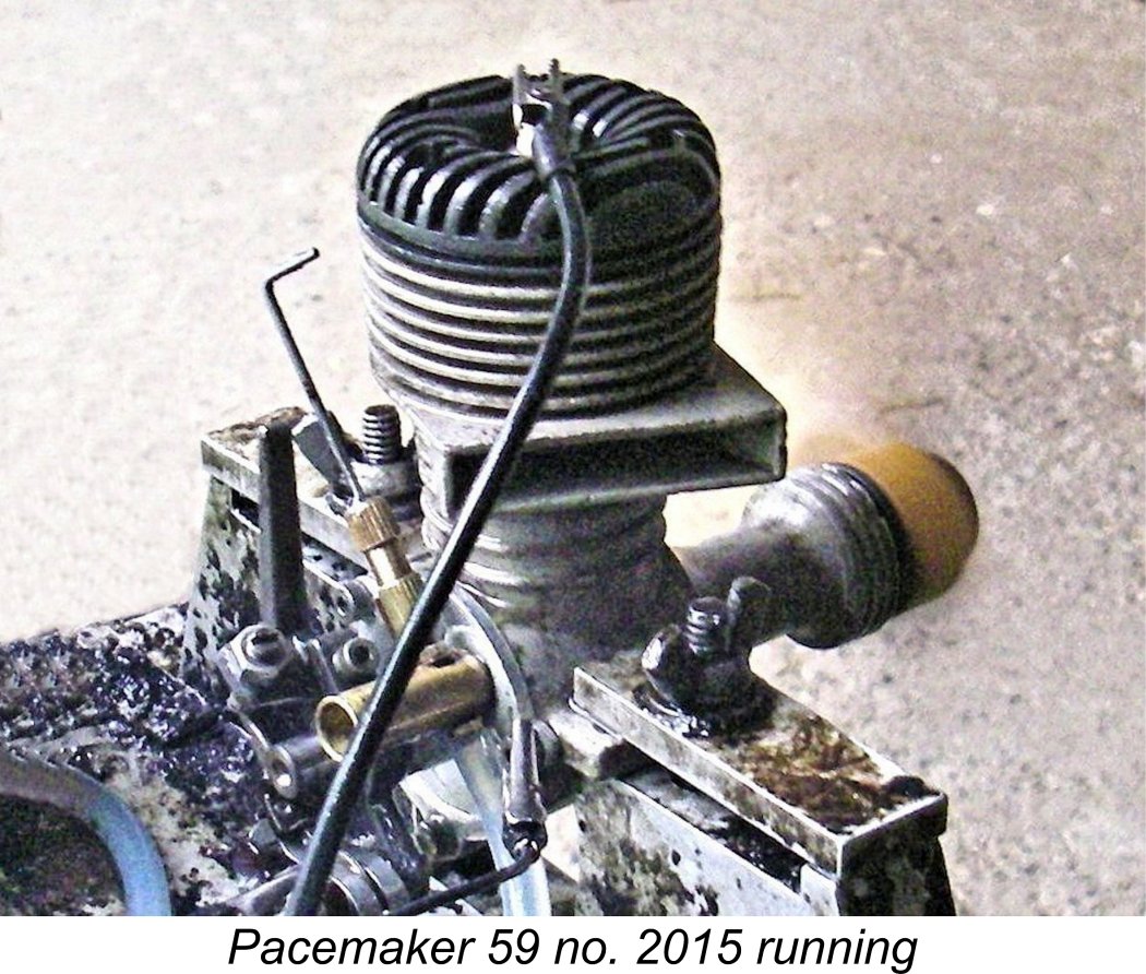
Apart from the anticipated noise level, I was actually looking forward to conducting this test! The rearward location of both needle valve and timer control arm offered a level of safety With the engine securely mounted in the stand, I tested the plug and ran my usual timer function check. Having confirmed that everything checked out perfectly, I re-installed the plug, filled the tank, set the timer for the points to open around ten degrees before top dead centre, opened the needle some 4 turns, administered a couple of choked flicks plus a prime and switched on the ignition. The commendably free feel imparted by the ball races made the engine very easy to flick despite the rather high compression ratio coupled with a sizeable displacement. However, unlike most of the sparkies which I've tested, this one proved to be a bit of a challenge to start, at least initially. Indeed, it seemed very reluctant to fire at all, and when it did the resulting firing stroke was pretty weak. I re-checked the plug and ignition system, finding nothing wrong. Having done this, I went back to flicking. Eventually persistence paid off - I got lucky and the engine burst into vociferous life. As it turned out, this was one of those classic cases in which adherence to the instructions provided by the manufacturer would have saved me a lot of trouble! Those instructions specify 2 or 3 choked turns of the prop as the only required preliminary - no mention of a prime. Experience soon taught me that this was indeed the way to go. The Pacemaker does not like to be "wet" for starting - a bit of fuel in the case is all that's required. Once I figured this out, subsequent starts became quite straightforward, with only a few flicks being required.
With the timer advanced as necessary to give optimum speed and the mixture setting established, the engine ran perfectly - no trace of a misfire, and no tendency to sag. The compression seal was very well maintained when checked by hand with the engine at full operating temperature immediately following a leaned-out run - it appears that the piston/cylinder fit was perfect for the steel-in-iron combination employed. The one issue that I noted was a certain tendency towards above-average levels of vibration. The relatively high reciprocating weight resulting from the use of a big-bore steel piston and a rather heroic bronze alloy rod was doubtless responsible for this characteristic. A ringed light alloy piston and a bushed light alloy rod would probably have alleviated this issue quite significantly. It was actually the vibration factor which induced me to terminate the testing in the vicinity of 13,000 RPM. The Pacemaker turned the 12x5 Zinger prop at 9,500 RPM - a little below the anticipated 10,000 RPM figure cited earlier, but not unduly so. Since it was clear that the engine had more to give, I tried a number of lighter loads in a search for the peak. The following data were recorded.
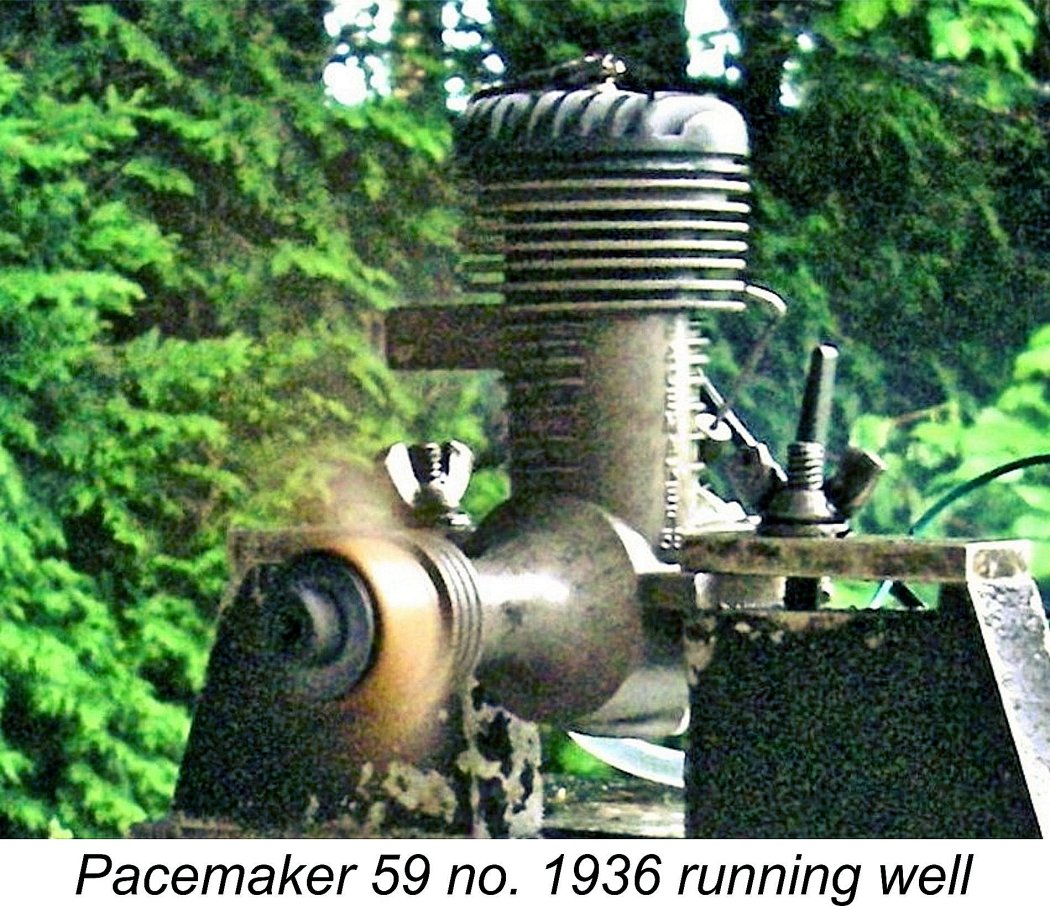
Although the above data are really too scanty to provide more than a rough indication of the engine's performance, there is a very clear implication that this example peaked at around 12,500 RPM, at which speed it was developing some 0.865 BHP. This is actually a very good figure for a general-purpose 1946 design of this displacement running on white gas - indeed, it comes close to matching claimed During the research for this article, I had an opportunity to try another example of the die-cast Pacemaker - engine no. 1936. This example proved to be just as good a performer as its twin tested earlier, starting easily and running flawlessly. It matched the figures measured for the first example almost exactly.
Just for fun, I tried the Pacemaker on glow-plug ignition using a 10% nitro fuel. It started very easily and was 600-800 RPM up on all props tested, with implied peak output pushing up towards the 1 BHP mark @ 13,000 RPM. However, the miniature glow-plug was not available when the Pacemaker was in production, nor had the use of nitromethane been adopted by the power modelling fraternity at large. Accordingly, these observations are of academic interest only. Even so, it's clear that the Pacemaker was one of the better Class C performers of its early post-war generation. Conclusion
Thanks entirely to that circumstance coupled with a relatively low level of ongoing promotional effort, the Pacemaker was produced in far smaller numbers than its sterling qualities might otherwise appear to have have justified. It was a little too large to simply “lose”, while its many positive attributes would have made people reluctant to throw it away even after they had moved on to other powerplants. Moreover, it performed very well in glow-plug guise, in which form a number of examples doubtless remained in use for some time. As a result, many of the engines that were produced have survived down to the present day, some of them in excellent condition. The vast majority of these are the later die-cast variants, which appear to have been made in considerably greater numbers than the original sand-cast models despite their lack of advertising. Nice examples of the Pacemaker seem to show up on eBay and elsewhere quite frequently. Oddly enough, they tend to sell for what I would consider to be far lower prices than the engine's qualities would seem to merit. Perhaps this is because so little information about them has previously been generally available. Whatever the reason, anyone interested should be able to acquire a nice example relatively inexpensively. Anyone doing so will find that they’ve received excellent value for money! __________________________ Article © Adrian C. Duncan, Coquitlam, British Columbia, Canada First published July 2025 |
||
 As all of my regular readers should know by now, my motivations for researching and writing these articles vary considerably. It may seem surprising to some of you that the rarity of a given engine is not among the major criteria upon which my selections are based. Some of my subjects are indeed rare, but that’s not the primary reason for their appearance in these pages.
 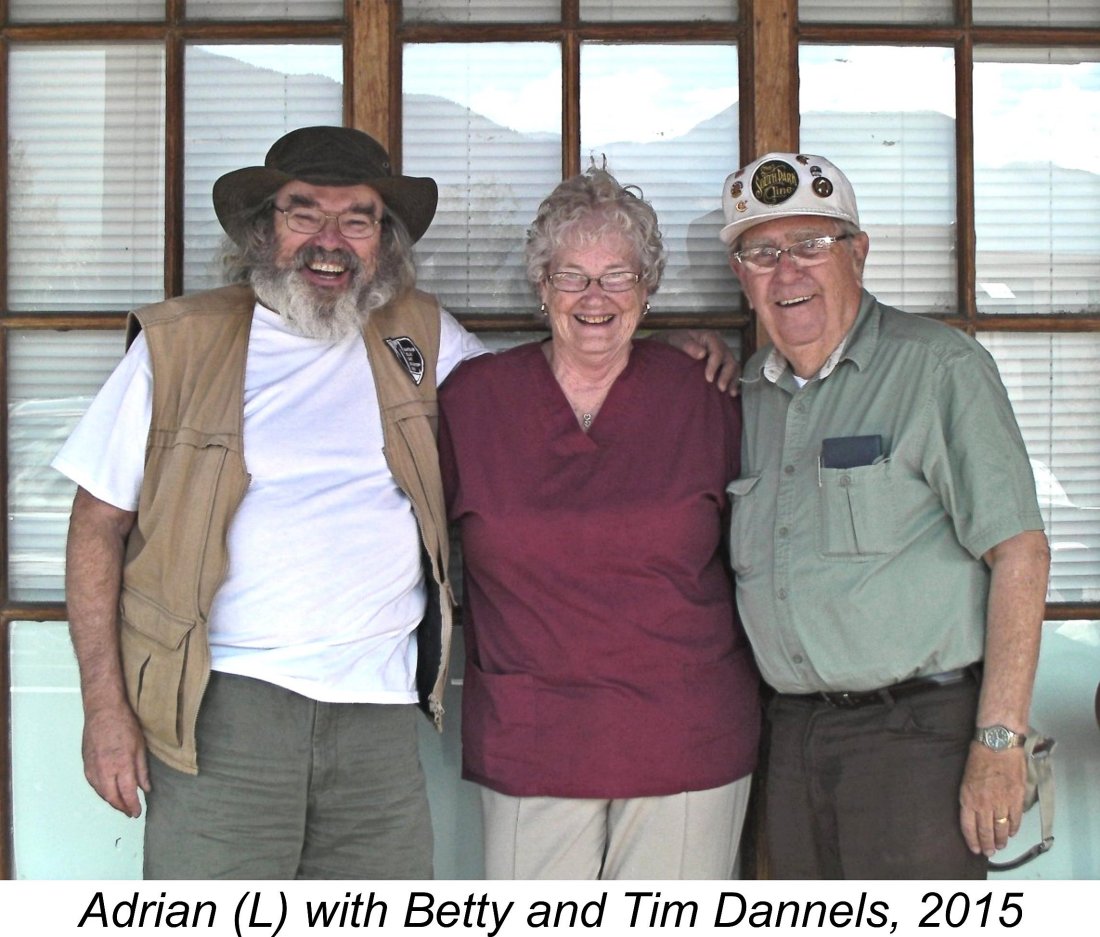 Normally I steer well clear of writing about American engines unless there’s a well-documented and previously-untold human interest story attached to them. This is because the vast majority of American production engines have been amply covered by my late and much-missed friend and mentor Tim Dannels, either in his invaluable “
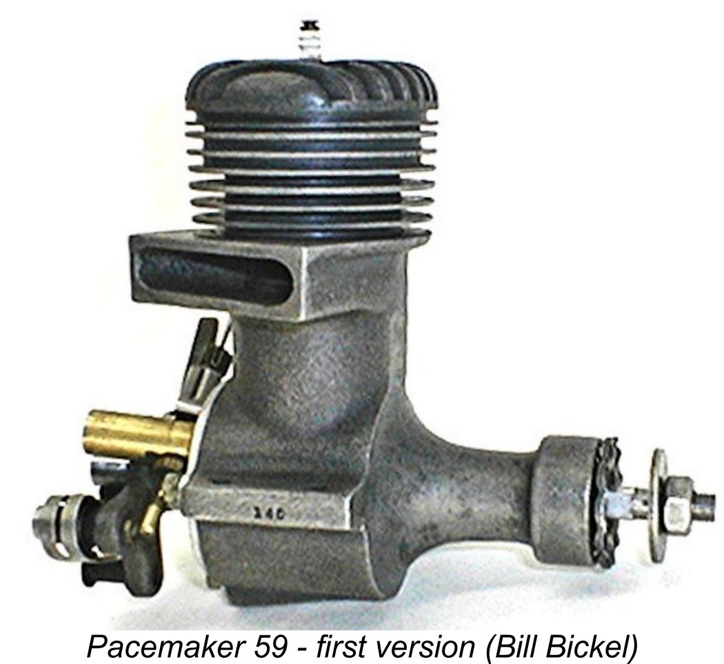
 The table which accompanied this text added little to the above description. Reading between the lines, it seems likely that Bill Siedler had previously been engaged in war materiel production and that the Pacemaker represented his initial effort to establish himself independently in the post-war US economy.
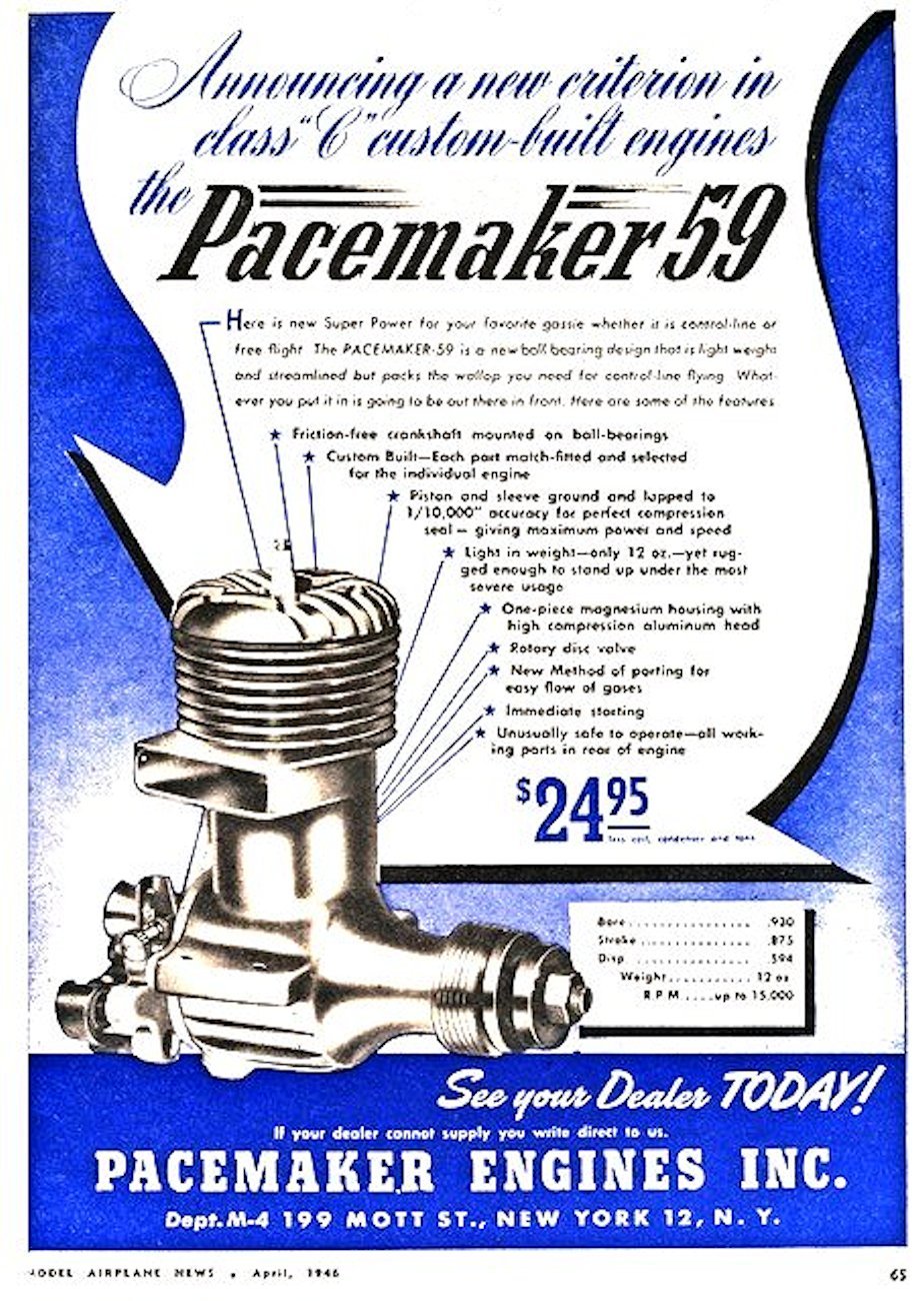
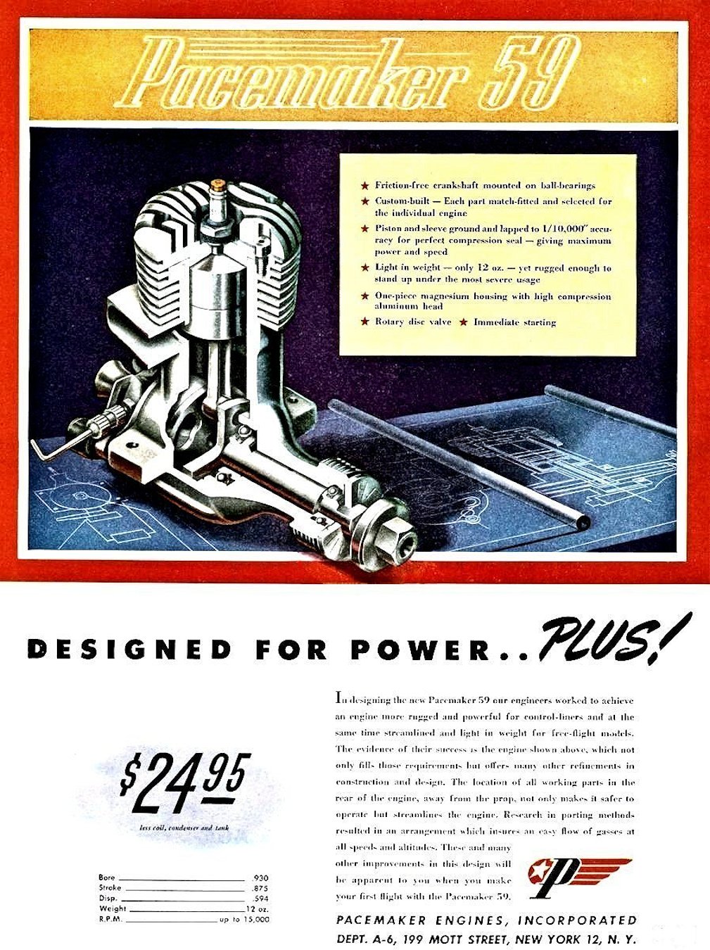
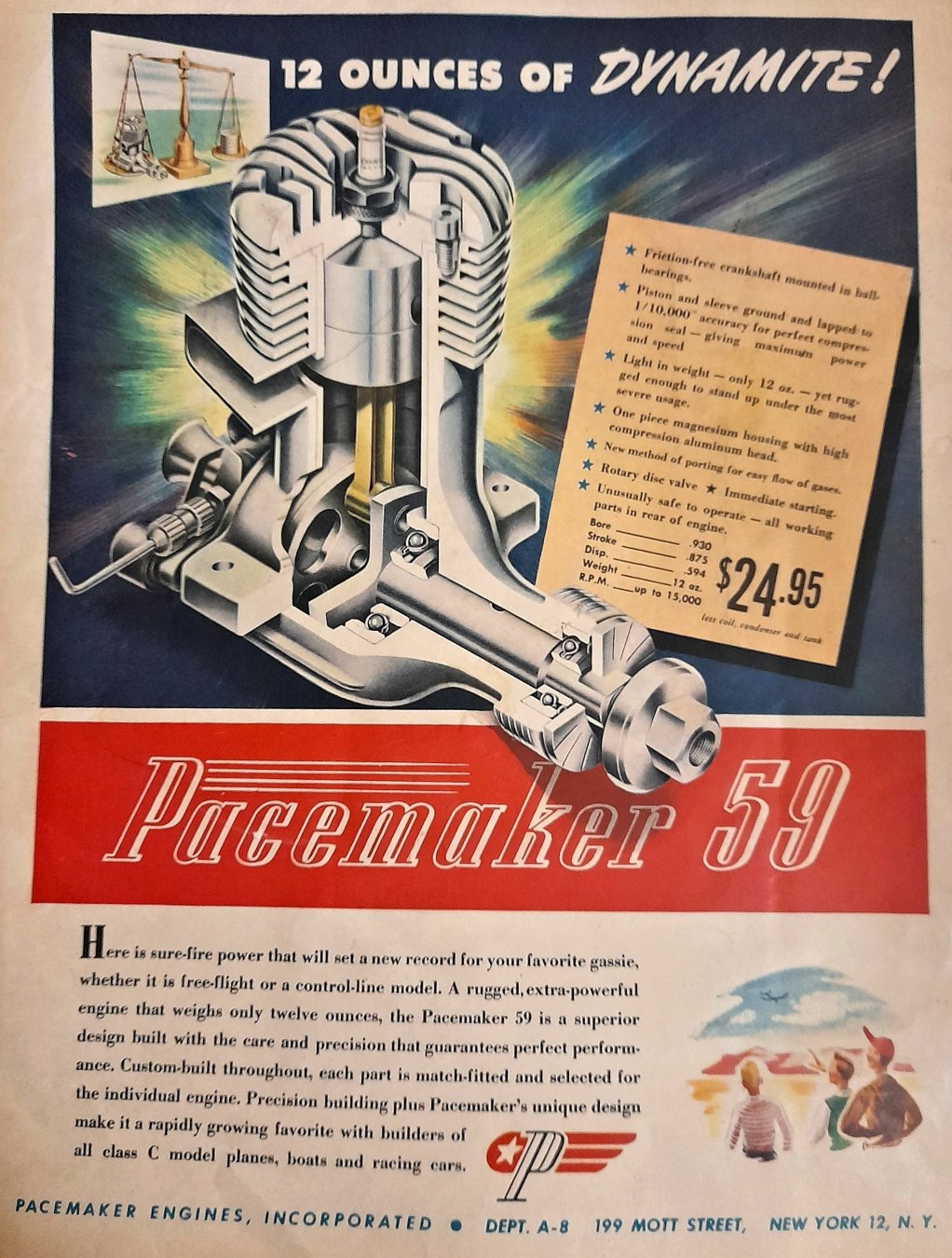
 The Pacemaker engines as originally marketed featured smooth rib-less sand-cast crankcases formed in magnesium alloy as illustrated above. All of the cited advertisements featured this version of the engine. I have yet to come across a Pacemaker advertisement featuring the ribbed-case die-cast version of the engine.
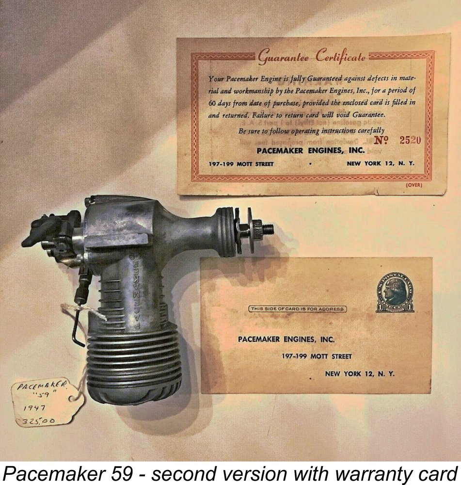
 It’s unclear whether or not Gotham actually resumed production of the Pacemaker in their own right. Given the devastating effect of their more or less concurrent takeover of the
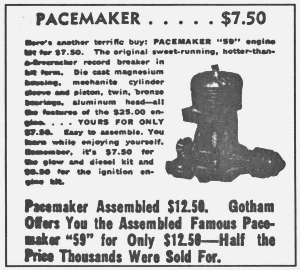
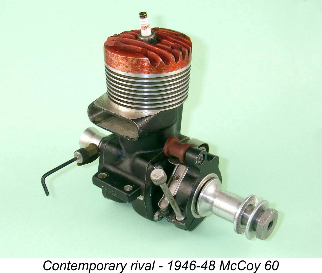
 It only takes one look to confirm that we’re dealing here with an engine displaying considerable design originality along with a healthy helping of ambiguity. I use the latter term because when set down on paper the engine’s use of cross-flow loop scavenging; a twin ball-race crankshaft; a short stroke; a high compression ratio; an automotive timer; metal-to-metal assembly without gaskets; and a disc rear rotary valve would normally be taken to place it in the “racing engine” category in a 1946 context. The use of a rear-mounted timer driven by the disc valve spindle would not contradict such a designation. However, in other respects the engine’s specification appears to point more towards general-purpose use - we’re not looking at a proposed McCoy-beater here!
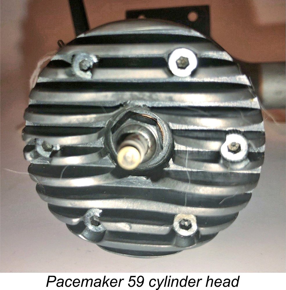 Starting at the top, the Pacemaker features a black-anodized cylinder head which is plentifully provided with cooling fins. According to the manufacturers, this component was machined from an aluminium alloy forging. The ¼-32
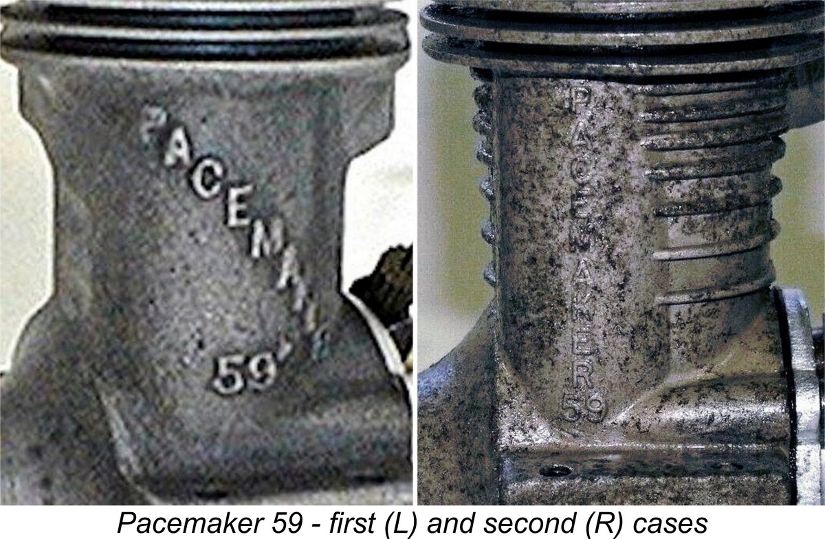
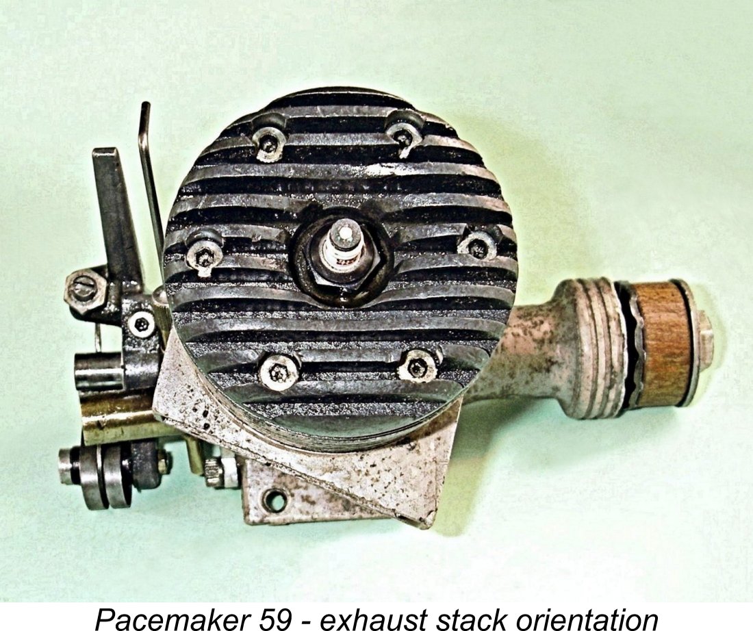
 clockwise direction (viewed from above) to bring the ports into alignment with the visible bypass and exhaust passages. The piston baffle is cut at a matching angle.
 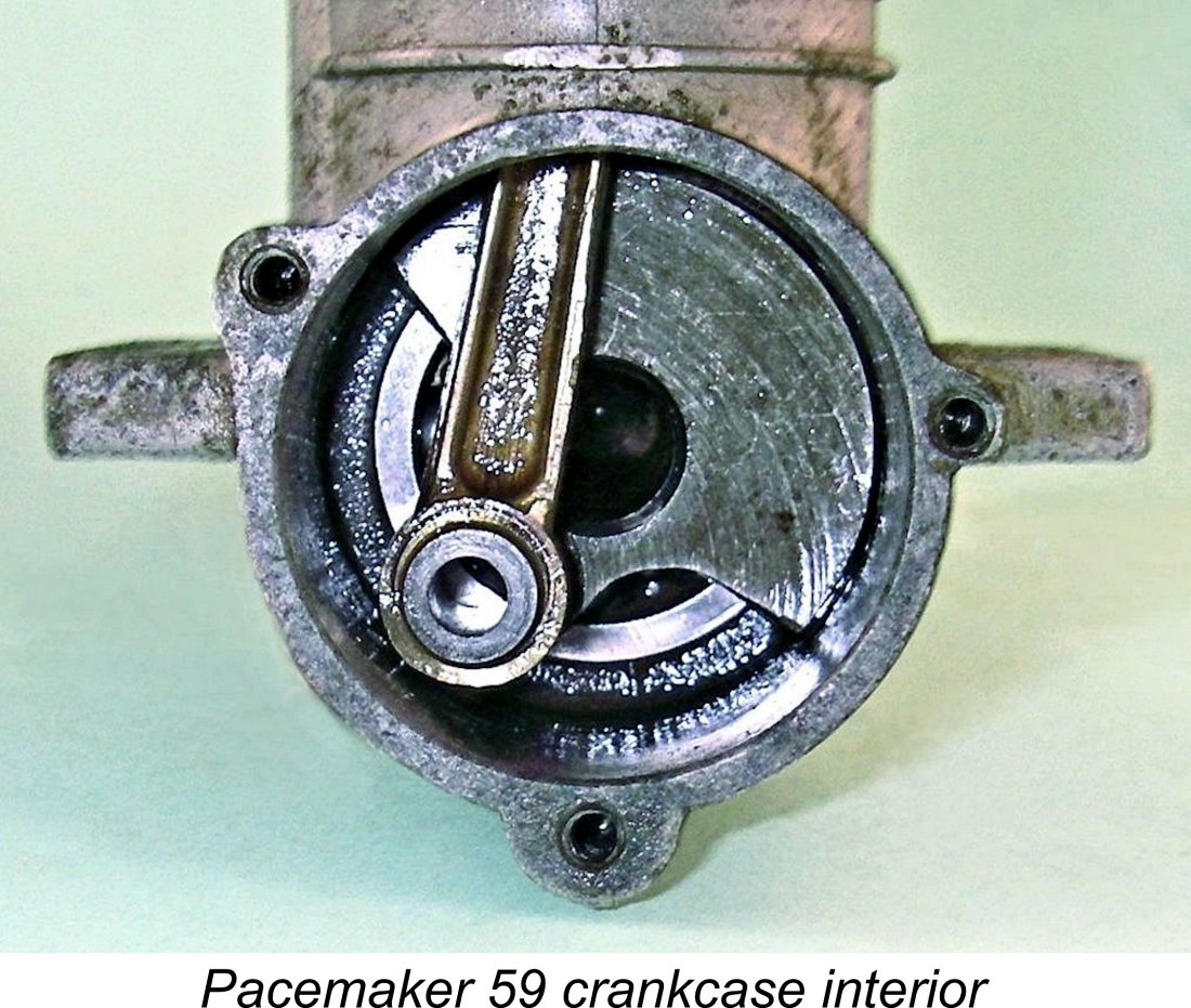 The conrod is a very sturdy forging in a bronze-aluminium alloy which was claimed by the makers to eliminate the need for bushings in either bearing. The one-piece steel crankshaft is another forging which is provided with a heavily counterbalanced crankweb. It is drilled out internally for lightness to a degree which I would have considered unwise. That said, the fact that this is a sparkie may keep the stresses down to a manageable level. The central hole does perform a useful function by supplying lubricant to the front portion of the main bearing through a hole drilled transversely into the main journal to communicate with the central hole.
 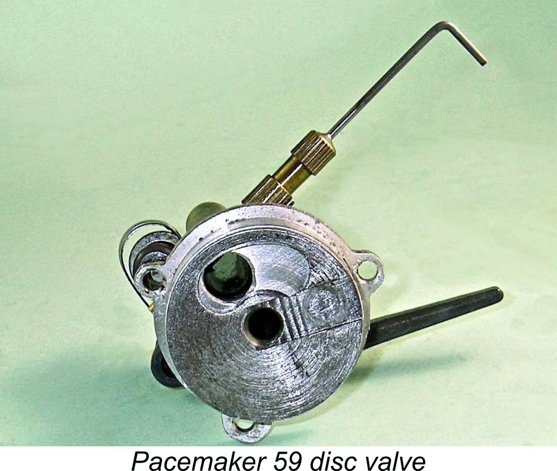 The rotary disc valve itself is machined from steel, with an integral shaft for support - almost like a second crankshaft without the crankpin. This shaft runs in a plain bearing formed in the backplate. It must be said that this is a very good design - apart from the excellent wearing properties of steel-on-alloy, disc alignment is very well stabilized. A 0.002 in. thick steel shim washer is fitted to minimize direct rubbing contact between the disc and the backplate.
 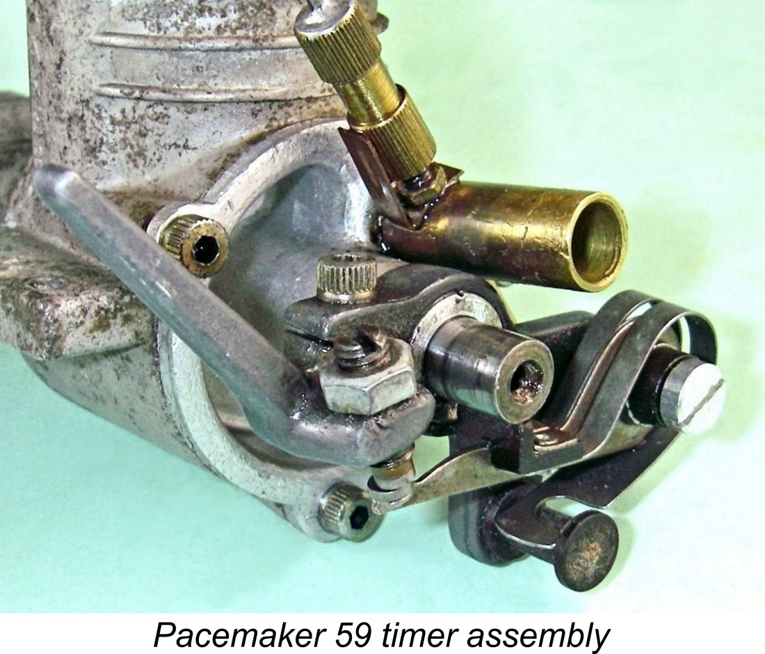 The valve draws mixture through a brass intake venturi which screws into the backplate at an unusual angle - another asymmetrical feature! At first sight this angle looks like a manufacturing error, but in fact it is made necessary by the need to provide clearance for the timer components. Venturi bore
 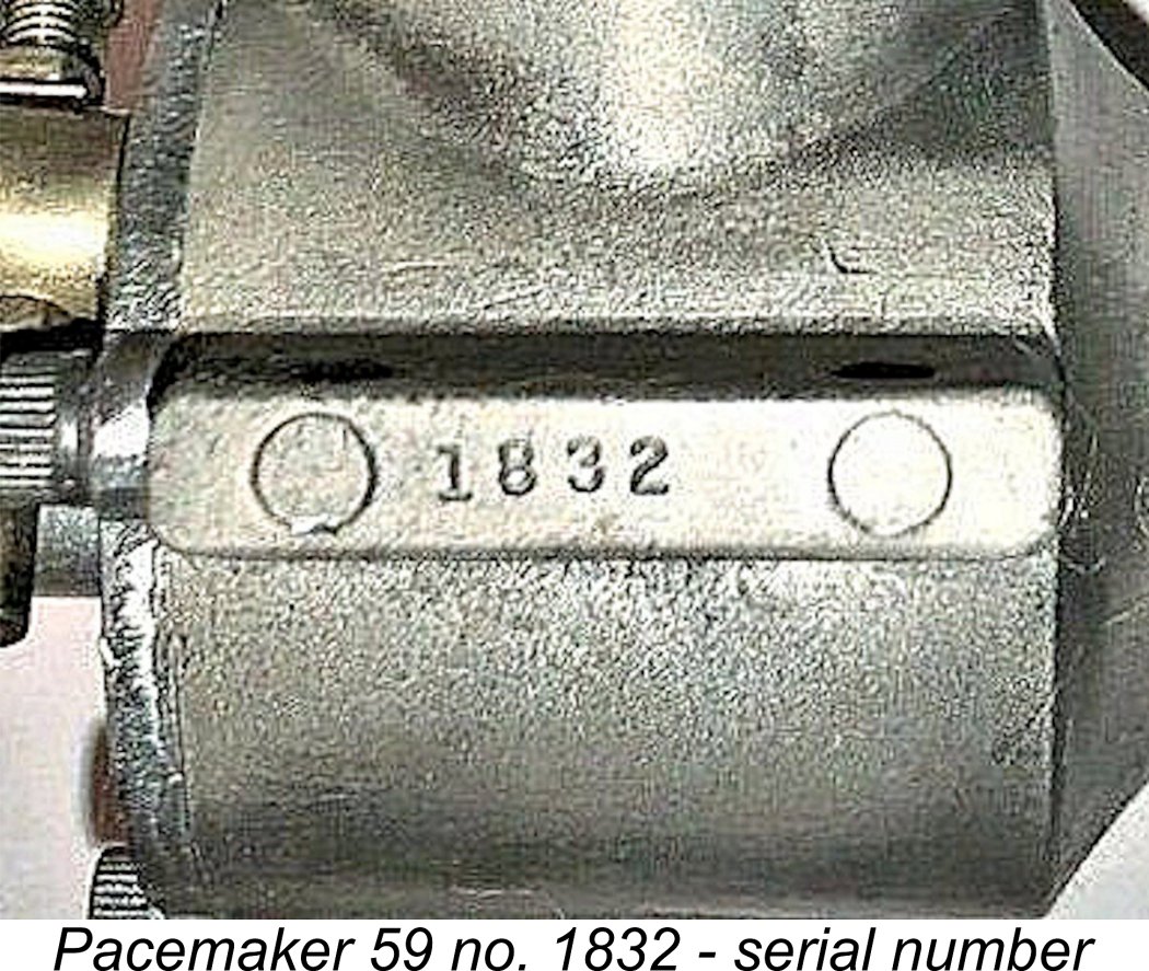 The engines all bore serial numbers which were neatly stamped into the outer end of the right-hand mounting lug (looking forward in the direction of flight). Presently-confirmed numbers for the original sandcast version cover the range from 140 up to a high of 851, while reported numbers for the later die-cast versions currently go from a low of 1250 up to a high of 2575. The implication is that the series started at engine no. 1 and that the sequence was continued uninterrupted through the introduction of the die-cast variant.
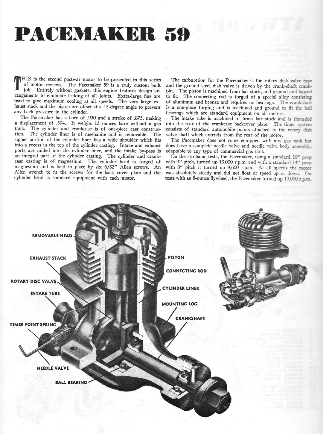 The Pacemaker 59 was the second engine to be featured in the series of engine reviews published by “Air Trails” magazine beginning in mid 1946. Unfortunately, these reviews provided relatively little performance data, concentrating for the most part on the construction features of their subjects. That said, the excellent sectioned views of the engines are quite informative as regards their construction.
 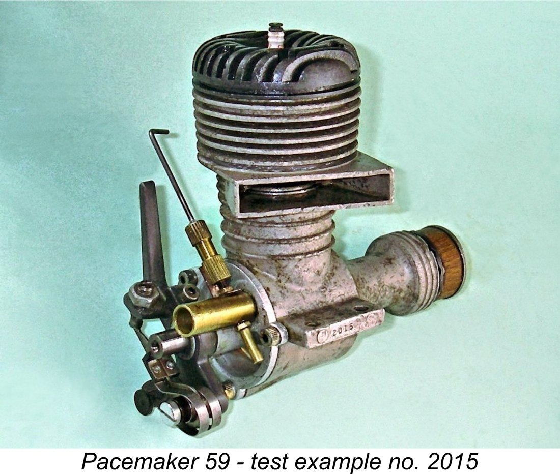 This brings us to the point where we have to drag fantasy back into the realms of reality! Only one way to do that - give the engine a chance to speak for itself (literally!). Fortunately, I had a suitable candidate example on hand in the shape of die-cast

 The 4 turns of the needle that I had applied proved to be just about perfect for a somewhat rich setting. I soon found that although suction appeared to be first rate, the needle setting was quite critical - since the taper is relatively coarse, only a small movement of the needle control made quite a difference to the mixture. Care was required to avoid a lean cut-out while going for that perfect run.
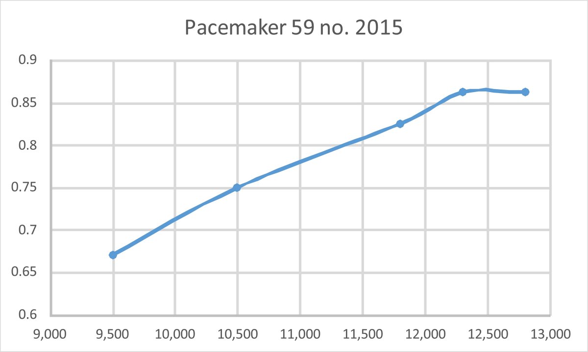
 The Pacemaker 59 was a highly original and well thought-out model engine of more than acceptable quality and well above-average performance for a 0.59 cuin. general-purpose model powerplant of its 1946 vintage. Its very short market tenure was not down to any design, manufacturing or performance shortcomings, but rather due to its instigator being deflected away from its production in favour of involvement in a completely different model engine manufacturing initiative.
| |