
|
|
Barstock Beauty - the Speed Demon 30 Diesel
The Speed Demon 30 was a 4.85 cc (.296 cuin.) American side-port diesel engine produced to very high standards in relatively small numbers for less than a year beginning in late 1947. Although it made little if any impression upon the contemporary marketplace, it is a very interesting motor indeed in technical terms. Furthermore, a number of aspects of the history of this engine have been the subject of debate among engine aficionados over the years. All of this makes the Speed Demon a particularly rewarding subject for research. My initial study of the engine and its background led to the January 2011 publication of the original version of this article on the late Ron Chernich’s “Model Engine News” (MEN) website. So why the article’s re-publication here? Mainly because my mate Ron left us in early 2014 without sharing the access codes for his heavily-encrypted site. Because no maintenance has since been possible, the MEN site is slowly but perceptibly deteriorating as the various links and shortcuts fail progressively - an inevitable process which can have only one ending in the long run. Some of the information on the Speed Demon could no longer be gathered if I was starting today from scratch today, making this article the sole record of certain aspects of the engine's story. I was unwilling to risk the loss of reader access to this information, hence the article’s re-publication here. Perhaps equally importantly, I’ve since become more broadly aware of the background against which this engine made its brief appearance. I’ve also been able to come up with a few additional illustrations in addition to improving upon many of those already included in the earlier article. Finally, a number of key links associated with the Speed Demon story were omitted from the original article, while many of those that were included have since been updated or replaced. All of these issues required addressing through the publication of a revised version of the article. Let's begin by considering a few of the previously-mentioned debatable points associated with this very unusual model engine. Origin and Numbers
In my personal view, two factors argue very strongly against this notion. Firstly, there is no record of the engine ever appearing on the European market or even being the subject of commentary in the European modelling media. If it was produced there, we would surely expect to find some evidence of a European marketing effort, or at least of some awareness of the engine in Europe? The fact is that we don’t. Secondly, the observation that all measurements and threads are based upon US (as opposed to metric) standards argues very strongly against a European origin, as does the use of what appears to be a made-in-USA prop driver from an OK 29 on the later examples.
The address in question is located at the oblique intersection of 83rd Street with Baxter Avenue, now being included in the The New York State location plus the fact that the later examples of this engine sport the apparent OK 29 pressed steel prop driver noted previously combine to suggest some kind of tie-in with the OK factory at Herkimer, which was also located in the State of New York. In addition, the bore and stroke measurements, the use of compression ignition and certain other data to be discussed below imply a degree of influence from the contemporary Drone fixed compression diesel manufactured in nearby New Jersey. Now the town of Herkimer is nowhere near Long Island (or New Jersey), being located well to the northwest, albeit still well within the New York State boundaries. So the geographic connection with OK appears to be rather tenuous. Nonetheless, the late Bert Striegler recalled reading somewhere that the Eastern Model Engineering Co. first became involved with the model trade as suppliers of parts to OK under contract, subsequently looking at the Speed Demon as a potential new cash-flow generator. This seems quite credible to me, albeit completely unproven. Overall, I believe that the notion of a possible European origin for this engine isn't really defensible when all the surrounding evidence is considered. Quite apart from the issue of the engine's origin, there has also been some debate regarding the number of these motors that were actually made. The late O. F. W. Fisher claimed a figure of 2,000 to 3,000 examples, but I've always been highly sceptical - on what basis did he make this claim? Moreover, if he was anywhere near correct, where are they now? The Speed Demon is a far rarer engine than we would expect if that many were actually produced.
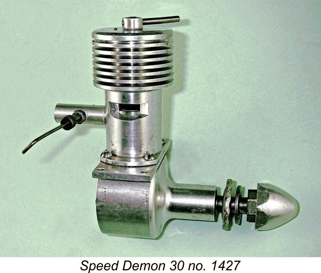
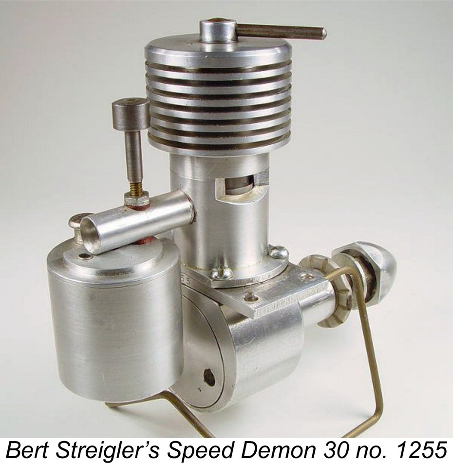
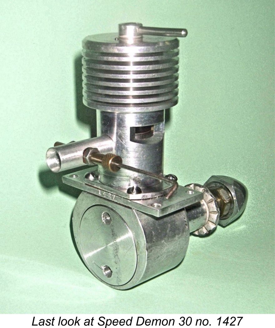
I have two of these motors - nos. 1008 (a very early example, assuming that they did indeed start at 1000) and 1427. The one illustrated by Fisher was reportedly no. 1355. Bert Striegler's example is right in the middle at 1255, while New-in-Box engine no. 1192 appeared some years ago on eBay. All of these numbers are consistent with the serial numbering sequence having started at 1000. OK, so how many were made?? Well, I am presently unaware of any reported examples with serial numbers under four figures, so it seems highly likely that they started at 1000 as claimed by my various informants. Furthermore, no. 1427 is the highest serial number that I have yet encountered, so I would guess that only about 500 examples were actually made, if that. The relative rarity of the engine today is certainly consistent with such a low figure. Still, the production of 500 engines of this quality was an achievement that commands respect! Now that we seem to have come to a few provisional conclusions regarding the US origin and relative rarity of our subject, it's time to take a closer look at the engine itself. Description
In a number of ways, the Speed Demon seems very much out of step with its time and place - it's an American-made side-port diesel engine which was competing in a marketplace which had by and large resisted the advent of the model diesel and was then poised to abandon it altogether. The most notable exception to this was the Drone fixed-compression FRV diesel A notable feature of the engine is the fact that it was constructed entirely from bar stock - no castings were used at any point. Furthermore, the engine used the "moving liner" system of compression In the case of the Speed Demon, the compression screw doesn't move up and down with changes in compression setting in the conventional manner. Rather, its vertical location remains fixed. Its threaded end engages with a The moving liner system is effective enough as far as it goes - it certainly allows for changes in the compression ratio, but a few seconds' thought will lead to the realization that this system of control inevitably changes the port timing along with the compression ratio! Faster running of course requires that the ignition timing be advanced. In a model diesel this is accomplished by increasing the compression setting. However, as you increase the compression ratio by lowering the cylinder in a design of this type, thus advancing the ignition timing, the ports necessarily move downwards also.
In any event, this probably wasn't much of an issue with the Speed Demon given the relatively low and narrow speed range within which the engine was at its best. Because of this factor, the required range of compression adjustment wasn't that great. In fact, as the Drone, Micron, Bonnier and Owat diesels proved, at such low speeds you can get away with fixed compression and still obtain a useful performance! Regardless, the fixed openings in the outer cylinder casing of the Speed Demon are suitably enlarged vertically so that they don't blank off the cylinder ports at any particular compression setting.
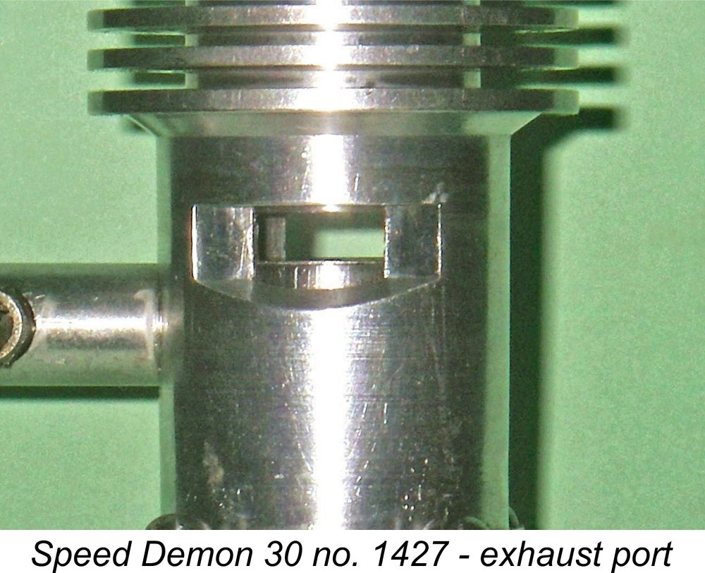
The Speed Demon gets around this problem by having a vertical hole drilled off-centre through the top of the outer casing to the rear of the comp screw. This hole is aligned with a similar hole drilled part-way through the actual cylinder head itself - in fact, the two holes were almost certainly drilled at one setting with the engine part-assembled. A 1/16 inch diameter metal dowel is fixed in place in the hole within the inner cylinder head. This dowel passes through the corresponding hole in the outer casing in which it is free to move up and down. It thus prevents axial rotation of the cylinder liner while leaving it completely free to move up and down as the compression setting is adjusted. The tip of the dowell is clearly visible in the attached close-up image. The compression screw is threaded 10-32 UNF below a flange which locates the screw vertically in the top of the outer cylinder casing to resist operating forces. This flange also serves as a stop to limit the degree to which the compression can be reduced by contacting the top of the internal cylinder "head" as the cylinder rises. Above the flange, the compression adjusting shaft is smooth, with a diameter of ¼ inch. This smooth section protrudes through a ¼ inch diameter hole in the top of the outer cylinder casing. An alloy collar fits over this smooth section to maintain the vertical location of the comp screw in the outer casing, thus creating a positive push-pull action. The adjusting lever is a 1/8 inch diameter piece of good-quality steel. This is threaded 5-40 on the end that passes through the alloy collar and threads into a hole drilled and tapped transversely through the compression adjusting shaft, thus securing the collar in place.
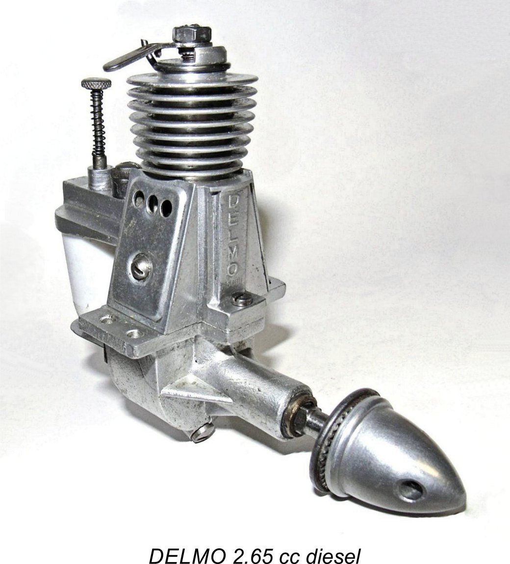
The one practical operating problem is the need to use some kind of friction lock on the comp screw, because there's no "stiction" in the system and the setting doesn't hold at all in actual operation. I used a bit of thick plastic tubing on the arm - this compresses between the arm and the head with sufficient friction to hold the setting, and it doesn't mar the surface of the head. The DELMO used a very neat tensioning spring to get around this problem - the makers of the Speed Demon could have emulated this with some advantage. Ken Croft came up with a somewhat similar device when making his superb 2 cc Speed Demon "replica" (see below).
The latter component incorporates the cooling fins. The crankcase, mounting plate and upper cylinder casing are secured together as a unit by four screws, with thin paper gaskets being used to ensure a seal. A screw-in backplate is employed, and this requires a pin spanner for its removal - please use the correct tool if you ever have to take one of these engines apart! The main crankshaft bearing appears to be a stock 1/2 inch O/D oilite bushing which is pressed into the main bearing housing. Turning now to the working components, the cylinder is made from a straight piece of what appears to be leaded steel tubing with a 5/16 inch deep "head button" pressed into the top and secured there in place of the more usual contra-piston. The upper surface of this "head button" has a blind central hole that is 1/4 inch deep and is tapped for the 10x32 UNF comp screw thread. It also has a 1/8 inch thick flange at the top which locates it vertically on top of the cylinder. This flange has the same 3/4 inch outside diameter as the cylinder. Two rectangular exhaust ports are cut in the cylinder wall, one on each side, with single transfer and induction ports being cut fore and aft respectively in the cylinder as well. The transfer port at the front of the cylinder is fed by a bypass channel which is internally milled into the front of the outer cylinder casing using a 1/2 inch diameter milling cutter. The induction port at the rear is fed by a straight venturi tube which screws into the outer cylinder casing on a tapered thread which maintains the orientation of the needle without a lock-nut. A conventional spraybar and needle are used for mixture control. The piston, crankshaft and con-rod are all massive affairs. The heavy piston is made of cast iron, with little attempt having been made to lighten it. The steel gudgeon (wrist) pin is pressed in, as it has to be to avoid fouling of the induction and transfer ports. The crankpin and gudgeon pin are 7/32 inch and 3/16 inch diameter respectively - very respectable sizes indeed! The steel rod has a massive look about it, having a column diameter of 7/32 inch. Basically, this engine is so over-built that you'd have to kill it with a sledge-hammer!
The crankweb is a full 1/4 inch thick - more massive strength! The crankshaft journal has a diameter of 3/8 inch, while the prop-shaft is 5/16 inches in diameter with a 5/16-24 UNF thread for the prop nut. The early models used a conventional split collar system on a round prop-shaft extension for mounting a "normal" centre-hub prop driver. Quite early on, they seem to have got hold of a supply of OK prop drivers, presumably by arrangement with the Herkimer factory - perhaps components manufactured for OK that turned out to be in excess of their requirements. Certainly, at that point they started machining a flat into one side of the prop mounting portion of the shaft and fitting what appears to be a standard OK 29 driver. No. 1008 (above at the right) is The engine was supplied with a double set of prop mounting fastenings. One is a conventional nut and washer, while the other is a spinner nut machined from hexagonal bar stock. This is recessed on the rear face to accommodate the nut, so it's clear that both fixtures were intended to be used together. It's my impression that the nut and washer were the main fixtures, with the spinner nut being more for show - although it may have served a secondary safety function as a lock-nut. My own engine number 1427 is little used, even retaining its guarantee certificate and spare parts list (left) along with the neat little separate plastic fuel tank with which these motors were originally supplied. I've actually never seen a mounted metal hang tank like the one on Bert Striegler's However, I have seen other examples which were accompanied by plastic tanks just like the
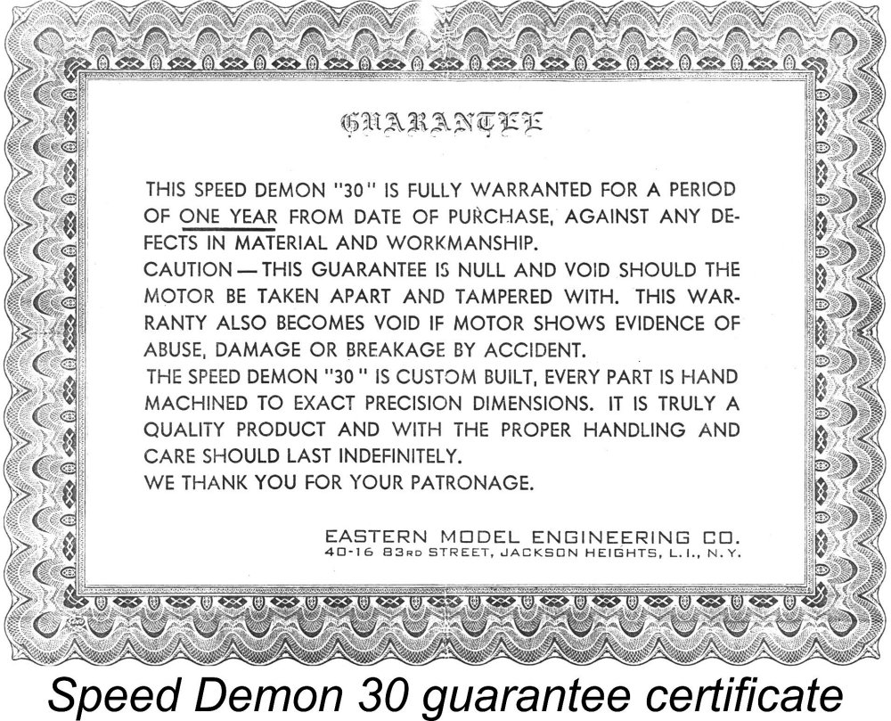
The plastic tank is interesting in that it doesn't mount on the motor at all - it has to be mounted elsewhere in the model. Just an accessory that was supplied as an extra as opposed to being an integral part of the motor. Note that the cost of the tank The quality of construction of these engines was superb - right up to the best "model engineering" standards. All fits and finishes in my examples are beyond reproach. The manufacturer's claims that they were "custom-built" and were "truly a quality product" are well supported by an examination of an as-new unit. The engines were guaranteed for a period of one year provided that they were not taken apart or damaged in a crash, but the manufacturers claimed that if well cared for and respectfully used they should last "indefinitely". In the context of a normal "modelling lifetime", I see no reason to doubt this claim. The Speed Demon in the Contemporary Media All right, now we know quite a bit about what it is, where it was made and how many were made. So, on to the next question - when wuz it made? Here the contemporary modelling media constitutes our best source of information. Having said this, it must be admitted that the dating issue remains somewhat clouded.
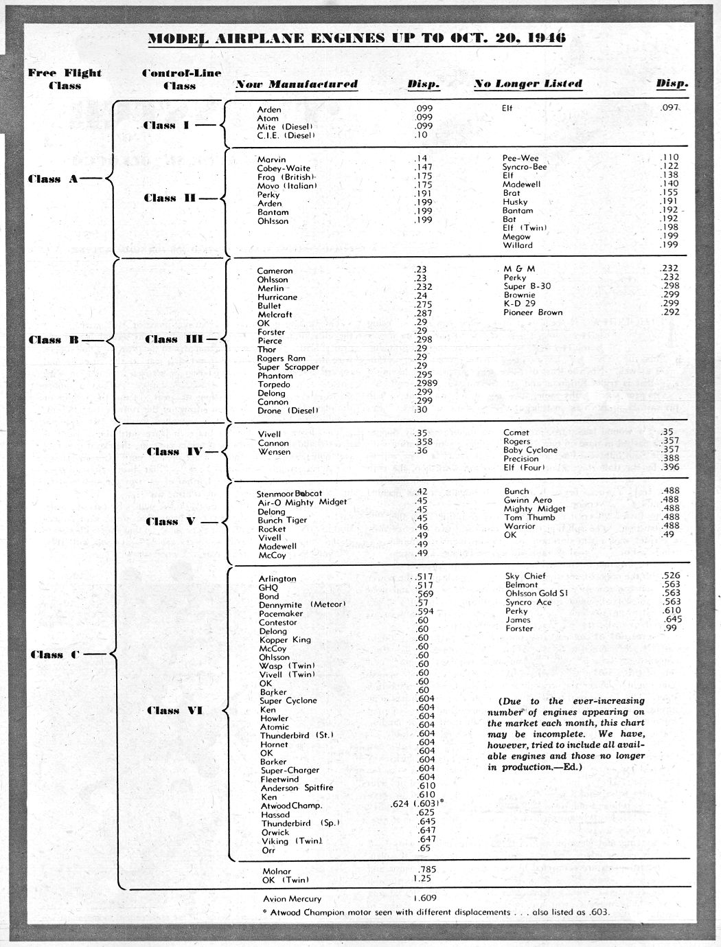
The table of engines (right) which was attached to this article was headed "Model Airplane Engines up to October 20, 1946". The Speed Demon was not included in this table. However, the engine was included in the photograph of a miscellaneous collection of engines with which the article was illustrated (below left). This appears to prove conclusively that the Speed Demon was in existence by April or May 1947 in time to be included in that June 1947 illustration. The photograph was clearly taken some time after the writing of the article. The Speed Demon is clearly visible at the extreme left of the image. Despite this, the Speed Demon was not mentioned in the article by Jack Bayha entitled "Care and Feeding of Diesels" which was published concurrently in the June 1947 issue of “Model Airplane News (MAN)“. It also failed to appear in the later piece by the same author entitled "Diesels Grow Up" which appeared in the December 1947 issue of MAN.
Reviewing the above evidence, it would seem that the first examples of the Speed Demon had made their appearance by April or May, 1947. However, it appears that neither Jack Bayha nor Jim Noonan had become aware of the engine when they wrote their respective articles in mid to late 1947. The release of the engine thus appears to have been a relatively low-key affair. The Speed Demon was included in the January 1948 article by Edward G. Ingram entitled "Model Engines for 1948" which appeared in MAN for that month. However, that article was published immediately following Ray Arden's November 1947 introduction of the commercial miniature glow-plug. That event must have had an instant dampening effect upon the sales prospects for the Speed Demon. By the time Ingram's subsequent 1949 survey was published in the June 1949 issue of MAN, the Speed Demon had disappeared from the scene without trace. Taking the above evidence as a whole, it would appear that production of these motors began in April or May 1947 and that essentially all of the engines were likely made in that year, with a few possibly being made in early 1948. Given the very small numbers produced, I'd guess that production had probably ceased by late 1947 or early 1948 after it was found that the engine couldn't compete either with the Drone Diesel or with the emerging glow-plug models, accordingly failing to attract any sales interest. Assuming that production carried on until, say, January 1948, the implied average monthly production rate of only some 50 engines confirms that we're not talking about a major factory production line operation here. Production rates may in fact have been considerably less than that, since a fair proportion of the engines produced may well have been part of the pre-release stockpile which any prudent maker would have on hand before launching a new design onto the marketplace. Such a short production life isn't really all that surprising - the engine is very heavy and lacking in power by comparison with the emerging glow and even diesel opposition as of 1948. Rather a boat anchor in many ways! I really can't see it ever having gained much traction in the contemporary US market, while there's presently no evidence to suggest that it was ever exported on a commercial scale.
If this was the case, the individuals concerned were presumably model engineers who earned a living in other ways, perhaps working for a larger business at the same location, while they developed and manufactured the Speed Demon in their spare time or as a business sideline. Possibly the supply of parts to OK as suggested by Bert Striegler was their main business during the Speed Demon's reported one-year development phase. Unless someone with first-hand knowledge of these long-ago events steps forward, we'll probably never know. Ingram's article describes the method of compression adjustment in considerable (and accurate) detail - old Edward clearly found it highly intriguing! He then does some bragging about the close limits to which the engines are constructed (with some justification, if surviving examples are anything to go by). The rod and main bearings are correctly stated to be oilite items. A subtle advantage claimed by Ingram for the engine which I hadn't previously thought about but which is undoubtedly true is the fact that the engine is mounted using a flat "plate" which separates the upper and lower halves of the main case and incorporates the beam mounting lugs at its outer ends. This arrangement is clearly visible in the attached images. If the lugs are damaged in a crash, all that is required is to replace the plate rather than replace the entire case. Perfectly true - and a very good point! The manufacturer's recommended fuel given in the write-up is 4 parts S.A.E. 30 oil, 4 parts ether and 2 parts "steam-distilled wood turpentine"! Wot, no kerosene?! The late George Aldrich commented that the use of turpentine as a component of diesel fuel would probably tend to gum things up a bit. I have no intention of finding out the hard way! Might have an interesting exhaust aroma, though ............ Since the commentary by Ingram appears to represent the Speed Demon's sole starring appearance in the contemporary modelling media, it's worth reproducing here in full. This commentary appeared as one paragraph in a much longer article entitled "Model Motors for 1948" which appeared in the January 1948 issue of MAN. The paragraph on the Speed Demon reads as follows: "A unique feature of the Class B Speed Demon Diesel, placed on the market by Eastern Model Engineering Co. after about a year of experimental and design work, is the method of varying the compression. What may be termed the outer cylinder is of aluminum alloy with an integral head. Within this unit is a steel sleeve, into the upper end of which is pressed a cap. The latter unit is the true combustion chamber. The compression ratio is changed by movement of the inner sleeve unit up and down through the provision of an adjusting screw which engages with the cap and projects through the aluminum head where a lever is attached for turning it. It is stated (that) the clearance between the sleeve and outer cylinder is held to less than .0005 in., and as the surfaces are lubricated no leakage can occur. Another distinctive feature is the provision of a separate engine mounting plate which does away with the necessity of replacing the whole crankcase when the mount is damaged. All main engine components are machined from solid stock, and oilite rod and main bearings are used. The engine is operated on 4 parts S.A.E. 30 oil, 4 parts ether, and 2 parts steam distilled wood turpentine. It is stated (that) a Mercury plane in which a Speed Demon was installed showed good performance and a steady climb despite the fact that this model aircraft has a 6 ft. wingspan and is designed for Class C engines". The comment about leakage seems a bit obscure at first, but think about it; unlike a conventional engine, there's no gasket to ensure a seal between the cylinder liner and the case because of the moving liner! An O-ring could have been used, but wasn't. So the base compression seal is in fact completely dependent upon a close fit being maintained between the moving liner and the case below exhaust level, as well as an associated oil film. The makers must have anticipated being challenged on this point, and were ready with an answer! This must be what Ingram was referring to. The fit on my two engines is undeniably very close indeed. From the style of the above comments, I think it highly likely that Ingram took much of this info directly from some kind of promotional blurb prepared by the makers - it certainly reads that way with the repeated "it is stated" comments. Wish we could find a copy …….. but I think that a good chunk of the manufacturer's sales pitch is embodied in the above paragraph. The reported use of a Mercury test aircraft incidentally seems to me to offer further circumstantial evidence to confirm the North American origin of this motor. Ingram also included a quite comprehensive table of data on the various motors covered in the article. The data provided for the Speed Demon were generally fairly accurate, as follows:
As all previous commentators have noted, the engines are very well made indeed. Both of mine run extremely smoothly and are a snap to start. See below for some test data. They are definitely not "speed demons", though - they like big props and low revs! Respect that, and they'll run for ever for you, I reckon - they're built like tanks! The Head-Fixture Issue In the original write-up on the Speed Demon which appeared on the MEN site, Bert Striegler reported his impression that there was no mechanical fixture of the pressed-in "head button" at the top of the cylinder. This matter has now been clarified thanks to the fact that I was forced to disassemble the upper half of engine number 1008 to fix some major issues. One immediate benefit of this was the opportunity to confirm by direct measurement that this example has the published bore and stroke figures of 16.66 mm x 22.22 mm for a confirmed displacement of 4.85 cc. Both of my examples weigh in at a hefty 11.675 ounces bare, minus tank. Number 1008 had been the unhappy victim of some clown who had tried to convert it to glow-plug operation without having the slightest understanding of what he was doing! I had a devil of a time sorting out what he'd messed up!! He'd bored a bloody great hole in the top of the aluminium cylinder casing just for starters - I had to make a press-fit aluminium plug and have the seam TIG-welded by my former motorcycle racing mechanic, then re-machine the unit inside and out to eliminate the excess weld. You can hardy tell now. I also had to make accurate replicas of all of the compression adjustment components, which I was able to do using engine no. 1427 as my pattern. But perhaps we should thank this unknown butcher, because one very useful thing that I did learn as a result of this enforced restoration effort was the method of securing the pressed-in "head button" which seals the bore. This is another point which has been debated over the years, and now it's sussed out! You have to look very closely to see this, but after the bore was finished internally (except perhaps for the final lapping), the flanged "head button" (blind-drilled and tapped from the top for the comp screw) was press-fitted into the top of the cylinder and staked in place with two thin (1/16 inch diameter) piano-wire or silver steel dowels which are a very close fit (probably a press-fit) in a pair of holes drilled diametrically through the cylinder wall into the "head button" on diametrically-opposing sides, presumably after the fitting of the button. The subtle part is that these holes stop short of breaking through into the threaded hole provided for the compression screw. The final external finishing of the cylinder was done after this set-up was installed, and the very close fit of the dowels in their holes plus the fact that their outer ends are finished flush with the cylinder surface makes it very difficult indeed to see the evidence once that has been done! But it's effective - once those stakes are in place, that "head button" isn't going anywhere, as I learned the hard way! I only discovered this myself because I had no choice but to remove the old button on number 1008 thanks to the previous owner having drilled completely through it and tapped it 1/4-28 UNF, not apparently knowing that glow-plugs are threaded 1/4-32 UNS and also not realizing that this wouldn't work in any case due to the lack of any liner fixing! AARRRGGGHHHH!! I clearly had to make a new head button, but couldn't shift the old wrecked one for love nor money (you can understand why after reading the above description!). So I ended up very carefully machining it out! Immediately, the reasons for my troubles became plain - there were the remains of the two stakes plus the two holes through the liner where the stakes had gone! I made a new "head button" (copying my other one) and installed it just as per the original using a tight press-fit followed by staking from the sides using the original holes as a location guide for the blind holes in the "head button itself. I then had to re-lap the bore and make a new replica piston to fit, thanks to the abuse that I was forced to heap upon the poor old cylinder. But I did so, and everything now looks fine, works fine and stays together. I subsequently examined number 1427 very carefully and (knowing where to look and what to look for) was finally able to spot the ends of the stakes on that one as well. But you have to look really hard in just the right light! Running the Speed Demon
I also elected to test a fixed-compression Drone Mk. I (number 441, which is well run-in) at the same time on the same props to provide a direct comparison between the Speed Demon and the rival American diesel that must surely have been envisioned as its main contemporary competitor in the US large-diesel market. When the Speed Demon appeared (and for almost all of its short production lifetime), the Mk. I plain-bearing Drone was the 5 cc American diesel to beat - the Mk. II ball bearing Drone only appeared later in 1948 when the Speed Demon was at or near the end of its brief production life. So this comparison seemed fair to me.
The Speed Demon proved to be a cinch to start, although it did require a prime - choking merely had the effect of flooding the crankcase. Initially, I had to keep reminding myself about the reverse-direction operation of the comp screw, but I soon got the hang of it. The engine was very responsive to both controls, making the establishment of the optimum settings a relatively simple matter. Suction was excellent and running was extremely smooth across the entire speed range tested. In common with many larger low-speed diesels, it was found that compression had to be somewhat increased to start from cold and then backed off as the engine warmed up. I only had a handful of large props that were drilled out to suit the 3/8 inch diameter hub on this early example’s taper-fitted prop driver, so the tests were a bit scanty in terms of data obtained. Still, the available props did appear to cover the engine's preferred operating speed. Results were as follows, with implied BHP figures based on the power absorption coefficients for APC propellers kindly supplied by the late Gordon Cornell:
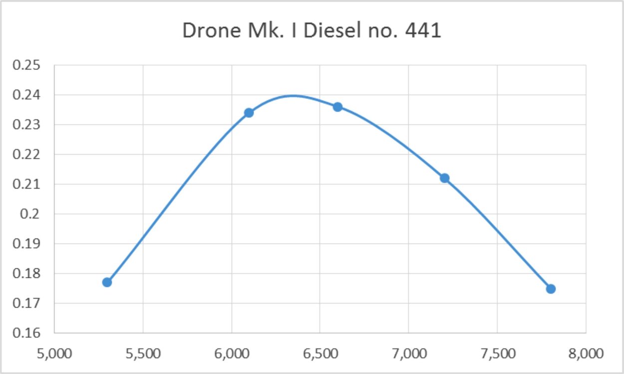
Not a stunning performance by any means, but the engine certainly swings quite a large prop and moves a fair bit of air in doing so. It would certainly do a good job of flying quite a large sports free-flight model. Plus the handling and running characteristics are first-rate, especially for a large diesel. The above admittedly sparse figures imply a peak output of around 0.143 BHP at 6,200 rpm. However, the above performance pales besides that of the Drone using the same props on the same day! The Drone was its usual good-mannered self, requiring only a couple of choked flicks on a full fuel line and a slightly leaned-out mixture followed by a short series of energetic flicks to start. It actually seemed to be having a "good" day, producing some quite impressive rpm figures as follows:
Running was extremely smooth on all props except the 10x6, on which the engine (as usual) displayed clear signs of under-compression. But since that prop turns well above the engine's peak, this is of little consequence. The above figures imply a peak output of some 0.240 BHP at 6,300 rpm - somewhat in excess of the maker's claimed peak output for the Drone, albeit at the maker's claimed peaking speed. As I said, it seems to have been a good day for the engine! On the basis of this comparative test using the same props on the same day, the Drone wins hands down. Clearly the Drone's combination of front rotary valve induction and more efficient loop scavenging makes a lot of difference. There's no doubt at all that anyone trying both engines would plump for the Drone with its greater power, lighter weight and equally easy handling. The later Mk. II ball-bearing Drone would have had an even greater edge. However, indications are that the makers of the Speed Demon didn't stay in production long enough to find out. Conclusion
Still, a very cool motor! Not a powerhouse by any means and rather overweight, but a very well-made and dependable unit with excellent handling characteristics and buckets of torque as As noted at the outset, there are no castings used anywhere and it would not actually be at all difficult to make a pretty good repro - they undoubtedly exist. I've thought of making one myself, in fact - just never got around to it! Plus there's less incentive when you already have two originals; in any case, Motor Boy Ken Croft already beat me to the punch by making a superb half-size (displacement) "replica" Speed Demon! This worked out splendidly and may in fact re-inspire me to have a go myself sometime, someday.............. ________________________________ Article © Adrian C. Duncan, Coquitlam, British Columbia, Canada First published on MEN January 2011 This revised edition published here April 2024
|
||
 Time for a nostalgic ramble down Barstock Boulevard to take a look at a relatively obscure American diesel from the late 1940's - the rather inappropriately-named Speed Demon 30 from Long Island, New York.
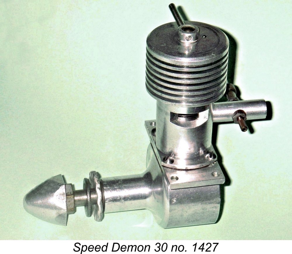 To open this discussion, questions have been raised regarding the geographic origin of the Speed Demon. It has generally been assumed to have been produced in the USA, but some have speculated (based on its design features plus a surviving letter which accompanied a replacement needle valve assembly with the late Bert Striegler's example) that it might in fact have been made in Europe and imported to the USA by its Eastern US promoters.
 Wherever it was actually manufactured, there is no debate at all regarding the fact that the promoters of the engine were based in the eastern United States. One of my two examples still has its guarantee certificate and spare parts price list, and both documents name the makers as the Eastern Model Engineering Co. of 40-16 83
 predominantly residential Queens borough of New York. As of 2021, the address was seemingly occupied by a second-floor skin care business called Glow Face, with its entry sandwiched between a salon/barber shop and a laundromat! It's quite possible that the site was occupied by a completely different building in 1947, perhaps even a residence.
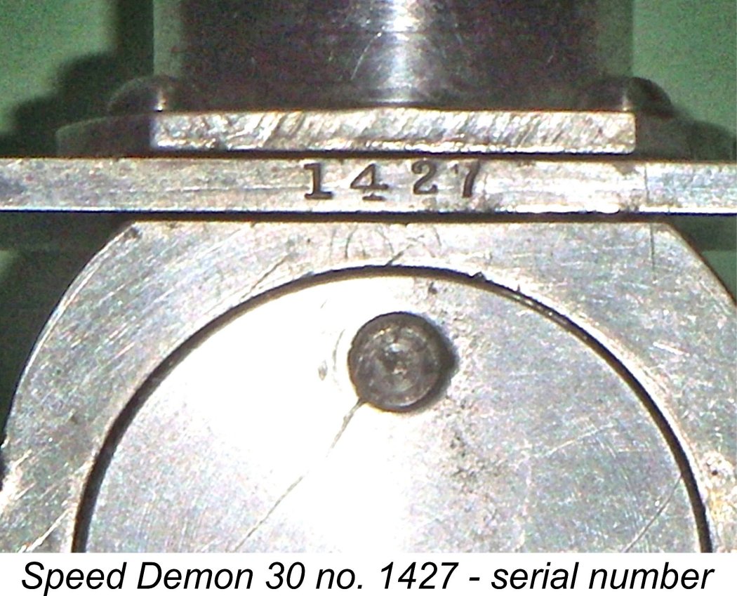 All of the known authentic Speed Demons carry stamped-on serial numbers, invariably appearing at the rear of the mounting plate which separates the cylinder casing from the main crankcase. My information (obtained directly from knowledgeable now-departed old-time sources such as Gus Munich, Art Suhr and others) is that the serial numbering started at 1000 and went on up from there - a not uncommon practise designed to inflate the perceived production figures.
 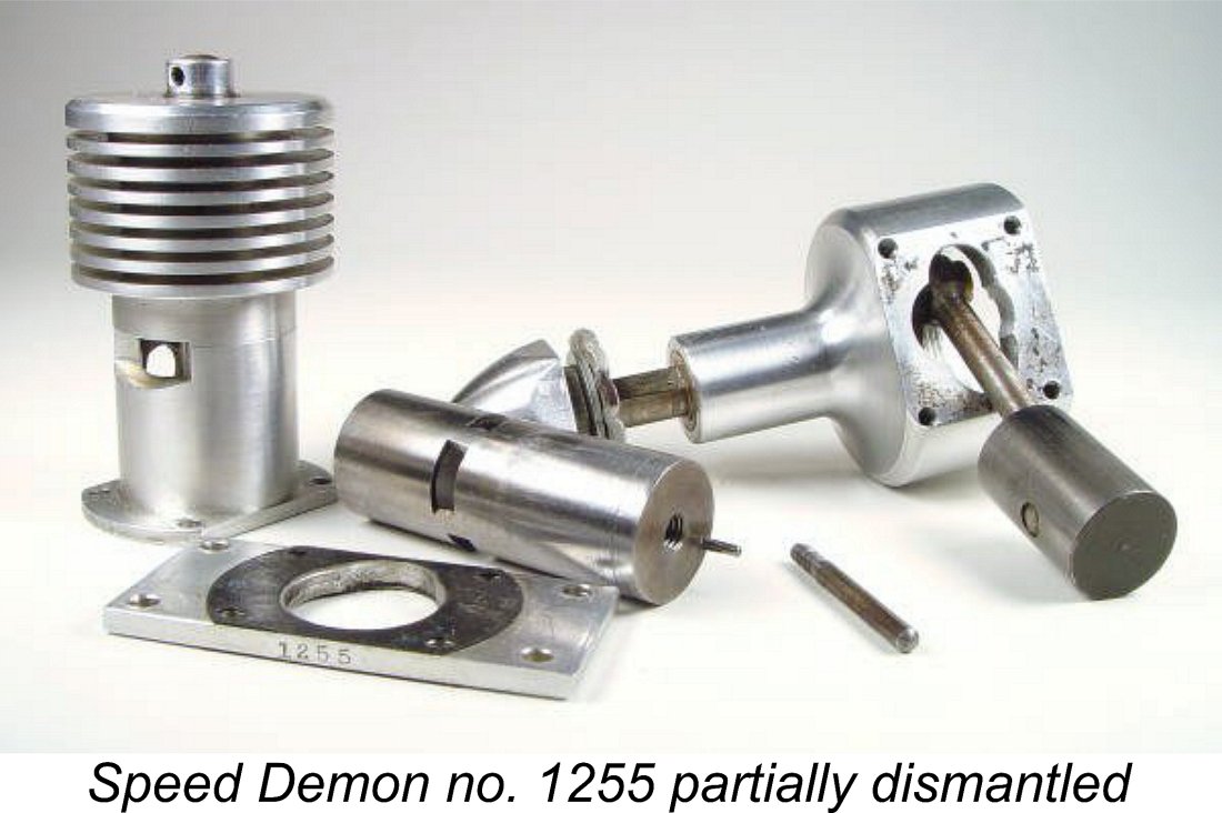 The reader's understanding of some of what follows may be enhanced by examination of the accompanying partially-dismantled view kindly provided by the late Bert Streigler. Bert's engine bore the serial number 1255.
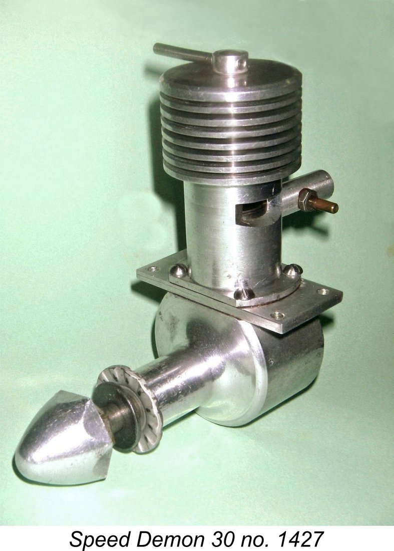
 adjustment whereby a blind cylinder liner with a fixed head (as opposed to a contra-piston) is moved up and down in its entirety by the action of the comp screw. This system had previously been used quite successfully on the early French
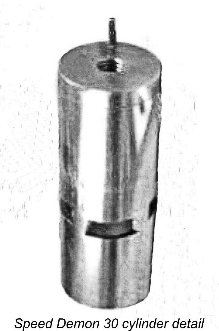
 As a result, the exhaust and transfer ports open later and close earlier (the opposite of what is ideal for faster running) while the induction port opens earlier and stays open longer. That of course is good for a higher running speed, but compromises abound........... oh well, the thing works, so I guess we can't ask for much more!
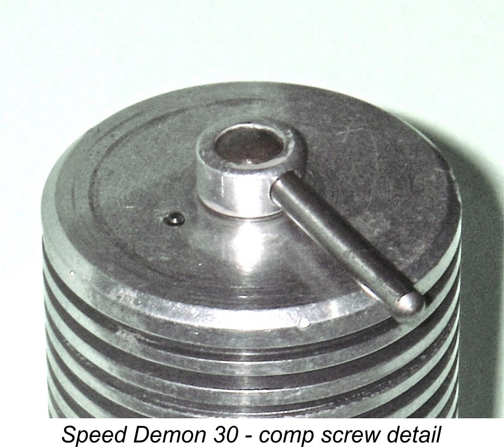 Another factor to consider with an engine of this design arrangement is the necessary freedom of the cylinder liner to move smoothly within the outer casing. As a result of this freedom, there's nothing to restrain the liner from revolving axially within the casing so that the ports no longer align correctly with the corresponding openings in the casing. Something obviously has to be done about this!
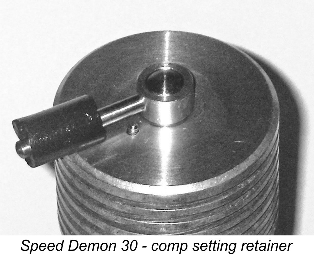 The compression screw arrangements described above have the effect of adding an unusual challenge to the running of these beasts - the right-hand threaded comp screw works backwards (think about it!). Turning the comp screw anti-clockwise (viewed from above) gives an increase in compression - the opposite of the usual arrangement! You soon get used to this, so it's not really an issue. The makers of the
 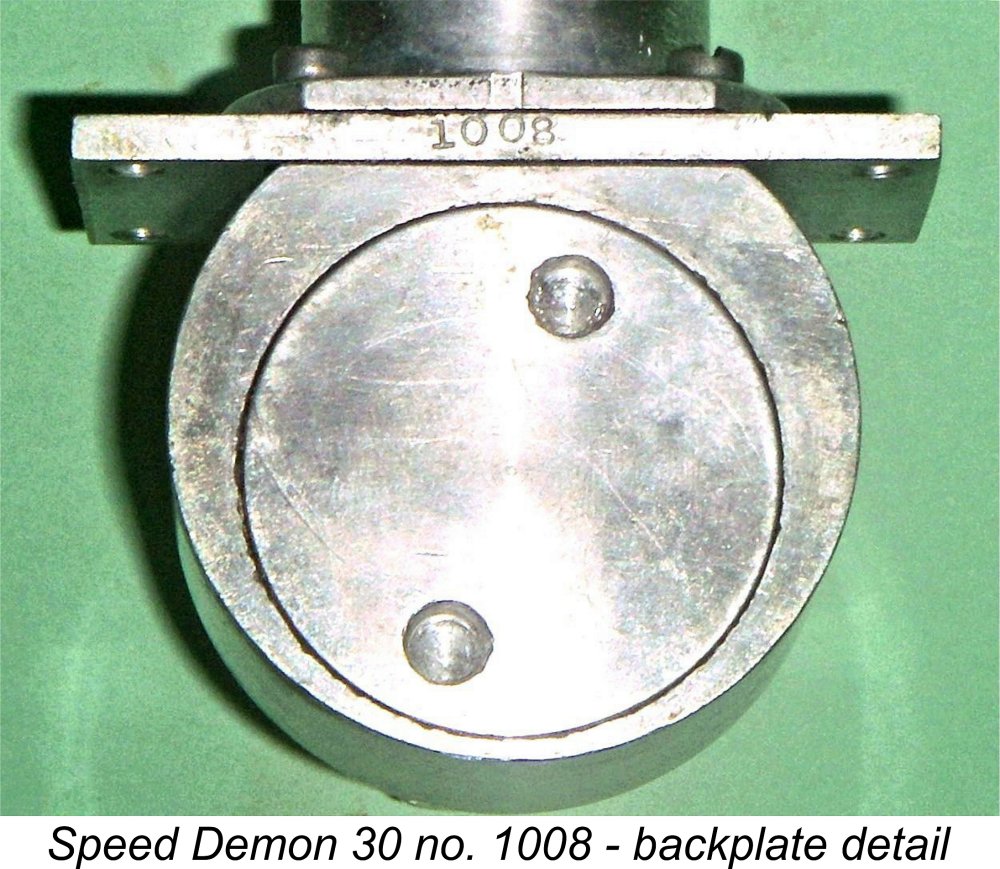 The crankcase is a simple turning from aluminium alloy bar stock with a flat area milled into the upper surface to facilitate the mounting of the upper cylinder components. One interesting feature is the fact that the main bearing and crankcase cavity are turned at an eccentric setting from the outer case. This creates extra material thickness at the top of the case where it's needed for the accommodation of the mounting plate and turned aluminium upper cylinder casing.
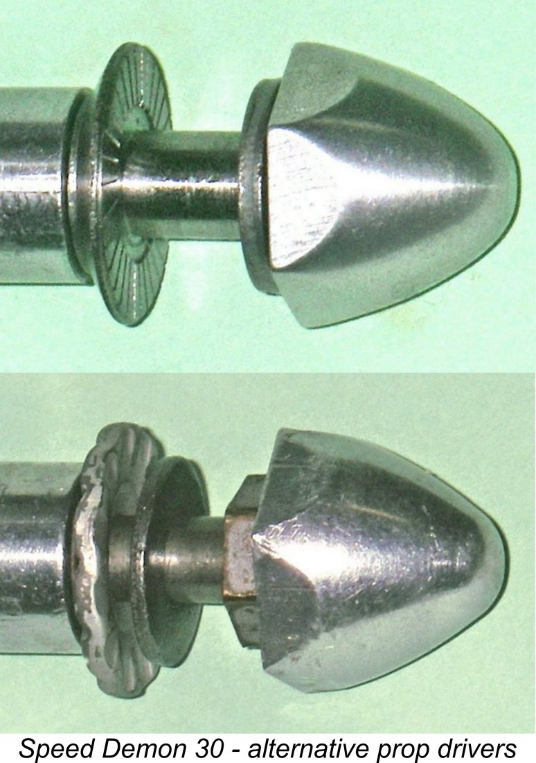 Both ends of the rod are bronze bushed, with the bushing on the big end being over-length to limit movement of the rod towards the rear of the crankpin. This extended bushing prevents easy disassembly of the engine and must presumably have been pressed in with the shaft and rod in place during the final assembly process.
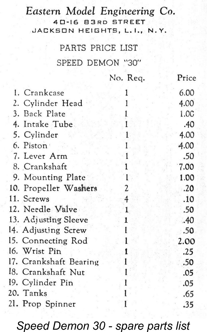
 example illustrated at the right, and in fact all but two examples of the engine which I have encountered over the years have had their needle valve assemblies set horizontally when correctly tightened - the two exceptions being Bert's example and the tankless example illustrated by Fisher. It is of course a simple matter to adjust the venturi thread to give a vertical needle valve alignment as required for the use of a back-tank like Bert's.
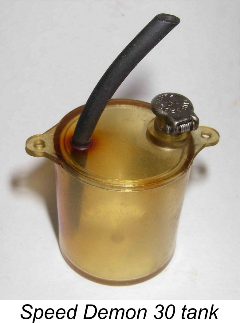
 The first appearance of the Speed Demon in the contemporary modelling media was noted by my eagle-eyed friend Gordon Beeby of Australia. Gordon found an article by AMA Scientific Leader Carroll Moon entitled "Pity the Poor CD" which appeared in the June 1947 issue of "Air Trails and Science Frontiers". This article was intended to provide Contest Directors (CD's) with information about the engines which might be expected to appear in competition to allow the CD's to confirm their Class eligibility. Both current models and engines no longer in production but still in wide circulation were included.
 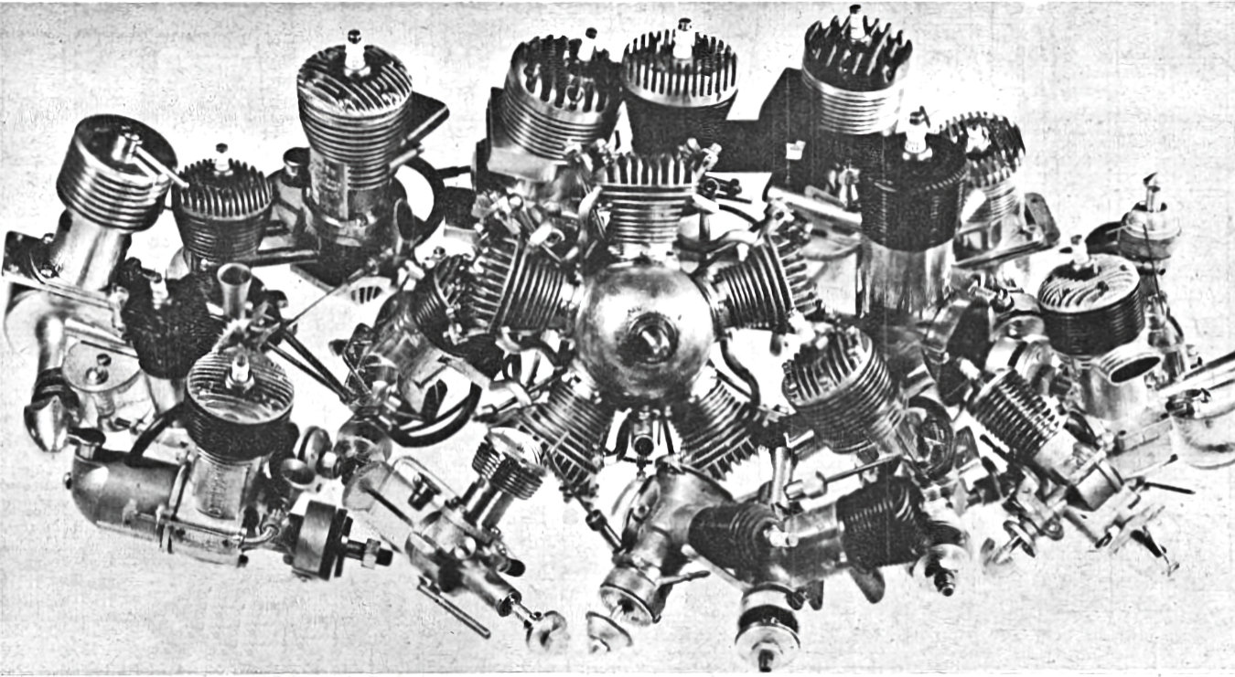 Perhaps most oddly, the engine didn’t feature in the article by Jim Noonan entitled "The Development of Diesels" which appeared in the September 1947 issue of "Air Trails and Science Frontiers". That article supposedly covered all the American diesels then available, along with a number of contemporary imported models. If the Speed Demon was indeed available as of mid 1947, we would have expected it to be included.
 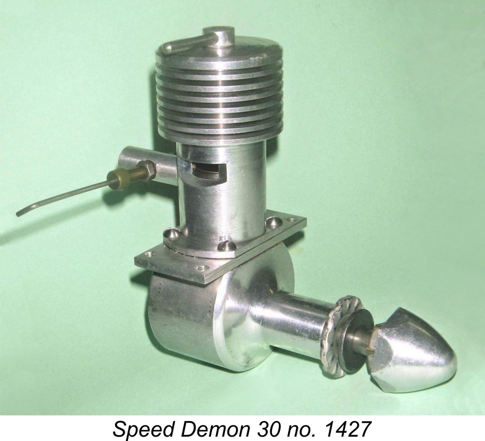 The January 1948 write-up by Ingram on the then-new Speed Demon is quite informative. It confirms that the engine was "placed on the market" in the USA by the Eastern Model Engineering Co. and was entering the market after "...about a year of experimental and design work". This comment is interesting insofar as it begs the question of what the makers were doing in order to eat while they did this work. In fact, the comment strongly suggests that the Speed Demon was most likely the product of a one or two-man "small workshop" operation like many small producers in Britain at the time. The very low production figures for the engine are certainly consistent with this scenario. The avoidance of the use of castings as well as the very high quality of construction both suggest a "model engineering" background in keeping with the company's name.
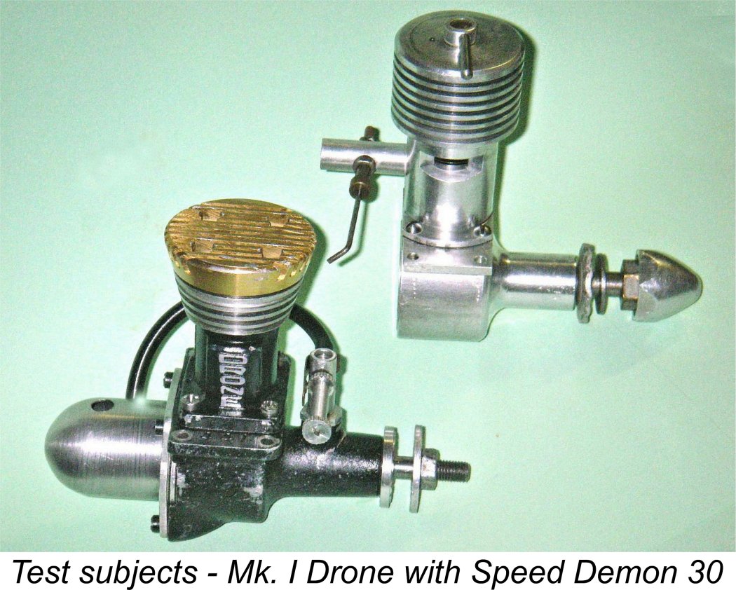 Having two examples of the Speed Demon on hand, I thought that the least that I could do was set one up and give it a run or two for this article. I wasn't worried in the least about doing this given the engine's very sturdy construction plus the fact that I'd previously run-in the new piston in number 1008 following its rebuild described above and had also put a few test runs on number 1427. I elected to use rebuilt engine number 1008 for this test since I wished to preserve number 1427 in as pristine a condition as possible.
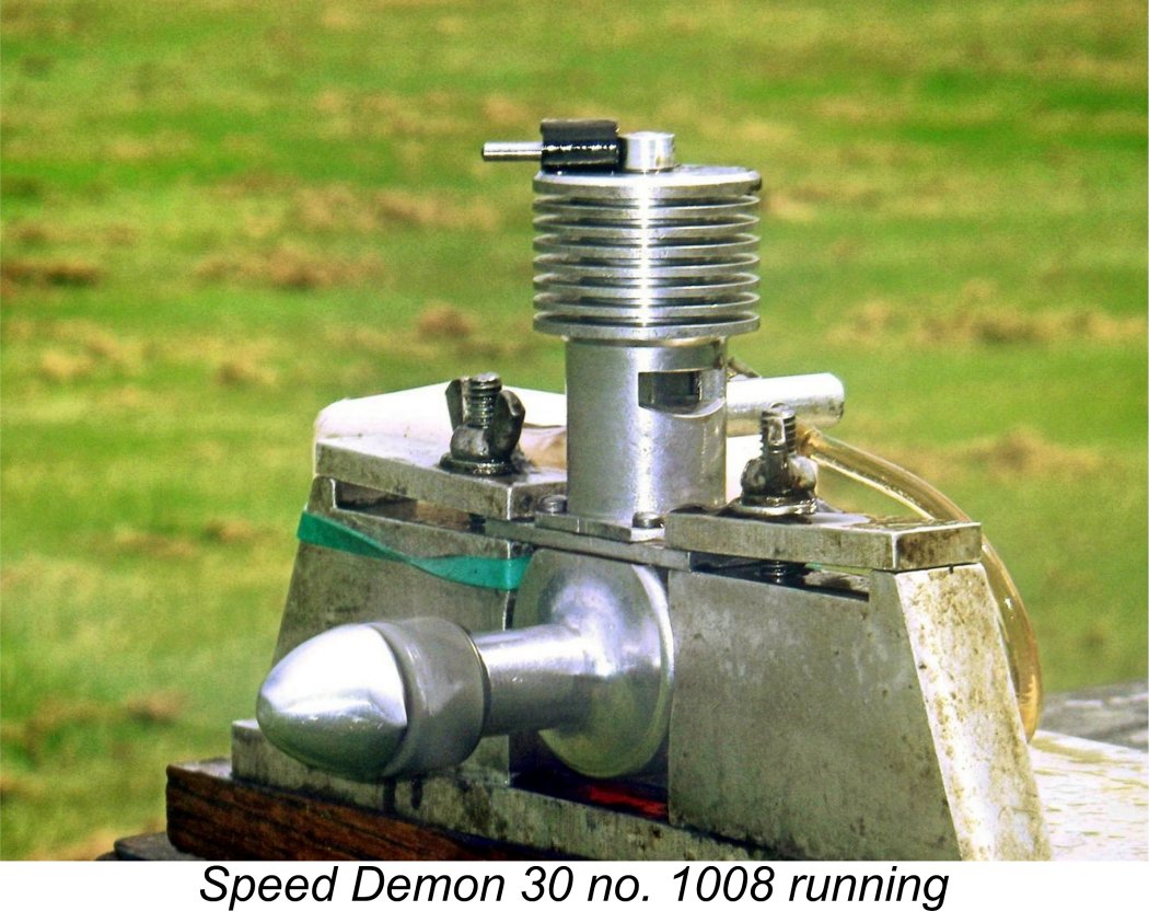 I ran the variable compression Speed Demon on conventional diesel fuel (no turpentine!), while the Drone was supplied with its own custom fixed-compression brew of 70% ether and 30% mineral oil (my usual mix for the Mk. I Drone).
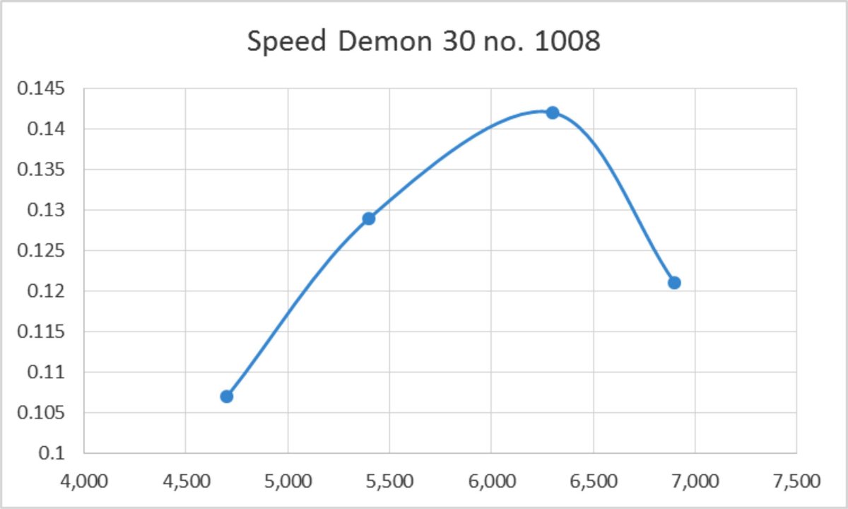
 If the Speed Demon had been released in Europe a year or two earlier, it would probably have sold quite well for a time at least. Quality was right up there, and the indicated performance is within sight of that found by Lawrence Sparey in his September 1948 test of the British-made
 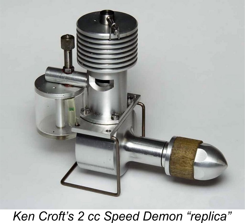 well as a few interesting design features. A very worthy effort by the unknown designer, even if it was somewhat distanced from its appropriate time and place.
| |