
|
|
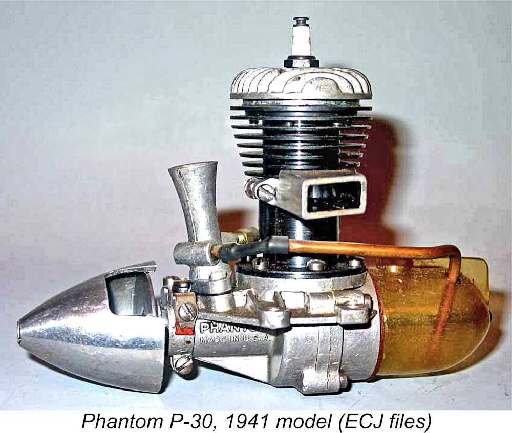
California Classic - the Phantom P-30
Before getting started, I’d like to acknowledge the outstanding help given to me as always by my late valued mate Tim Dannels, who pointed out that I seemed to have an unerring knack of picking up on topics which were never covered in the pages of Tim's now-discontinued “Engine Collector’s Journal” (ECJ)! This one's no exception - Tim never ran a focused article on the Phantom P-30. Despite this, Tim's work was of the greatest possible assistance - I really miss him. The information presented in his outstanding “American Model Engine Encyclopedia” (AMEE) was invaluable in pointing me in the right direction, while Tim was his usual generous self in providing a number of fine images from his seemingly inexhaustible ECJ files. Sincere thanks to my greatly-missed friend! Now, to get the ball rolling I have to set the stage by summarizing the manner in which Bill Atwood became incorrectly associated with the Phantom name. Bill Atwood’s Early Career
Over time, Bill further developed his flying skills to the point that by 1930 he had qualified for some powered flight instruction in Curtiss Jennies. He also maintained his interest in gliding, taking only 16 months to design and construct his own contest-winning sailplane having a wingspan of 60 feet. He flew this aircraft successfully in sailplane competitions at Pacific Palisades, California. During the same period, Bill also became very interested in model aircraft, competing in his first US National Championship event in 1927 at Memphis, Tennessee at the age of 17. His aeromodelling activities soon extended to indoor flying as well, an interest which he was to maintain for many A machinist friend of Bill’s named Bert Cundiff was buying castings from England and using them to construct examples of the model boat engines designed by Edgar T. Westbury. In 1928, after studying Westbury's articles and Bert's engines, Bill characteristically decided that he could do better, immediately designing his own first engine, which he built in 1928 while still enrolled in high school. The castings for this 30 cc water-cooled boat engine were produced by the 17 year-old Bill Atwood in his own backyard. Bill machined the components in Bert Cundiff’s machine shop. For the next four years, he used this and other engines that he constructed to compete with other local boat modellers, including Maynard Clark and Mel Anderson. Upon leaving school, Bill went to work as an aeronautical engineer for the Douglas Aircraft Company at Santa Monica, California. However, his involvement with full-sized aircraft by no means diminished his interest in models. In 1932 he built a nine-foot span model of spruce covered with butcher paper. To power this behemoth, Bill designed and built a 30 cc aluminium-case engine with cooling fins cast integrally onto the cast iron cylinder. It was obvious that models of this massive size were impracticable for the majority of would-be fliers. Clearly, smaller models and smaller engines to power them were both needed if the aeromodelling hobby was to prosper. Accordingly, in 1933 Atwood designed a new and far more compact model airplane engine of .364 cuin. (5.96 cc) displacement. This engine proved to be quite successful, leading Bill and his other noted engine-building buddy Irwin Ohlsson to show up at the 1934 US Nationals at Akron, Ohio with models powered by further-developed examples of this engine. Unfortunately, the weather at this meeting was extremely hot, and the two mixed their fuel using oil of too light a grade. As a result, the engines failed to perform well at this meeting.
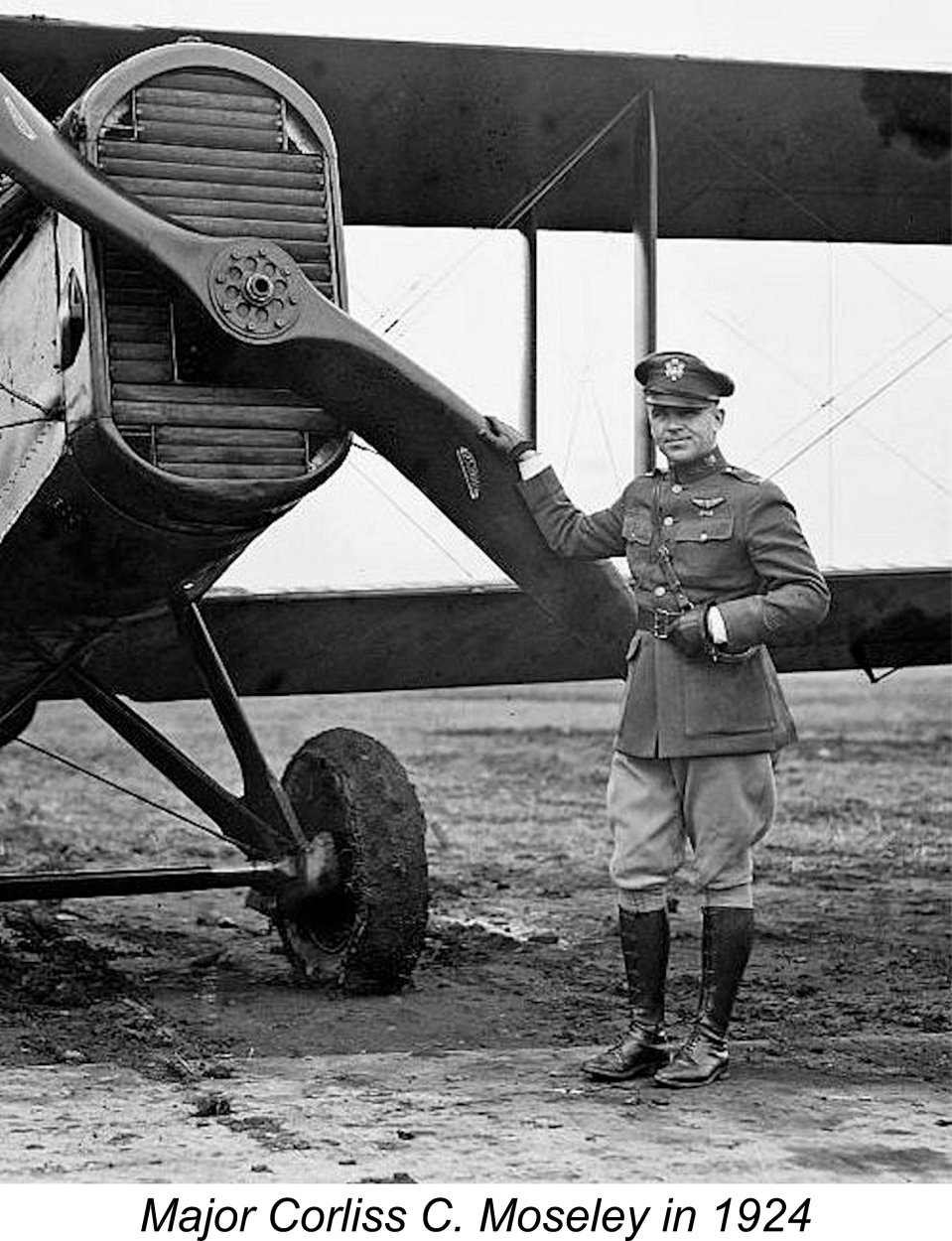
In addition to his managerial duties for Curtiss-Wright, Moseley ran a sideline business of his own called Aircraft Industries Corporation which was located at Grand Central Terminal. The main business of Mosely’s company was the provision of full-scale aircraft maintenance and repair services. However, Moseley was interested in model aviation and saw the commercial potential of Bill Atwood’s very successful model engine. Accordingly, in 1934 he entered into negotiations with Atwood to purchase the design. As part of the deal, Atwood left his job at Douglas Aircraft Company to go to work for Moseley at Glendale. Among his colleagues at his new company were Ira Hassad and Mel Anderson, both to become noted model engine designers in their own right. Mel Anderson was actually brought into Moseley’s operation on Atwood’s advice.
The engine was an immediate success in commercial terms, with almost 20,000 examples being produced during the next four years. Bill Atwood's winning gas models, the “California Chief” and “California Champ”, were also kitted by Aircraft Industries Corporation. 1938 was a pivotal year for Bill Atwood, because it was in that year that he left Moseley and Aircraft Industries Corporation to go to work for the Automatic Screw Machine Company which had been carrying out most of the production work on the Baby Cyclone at its Los Angeles plant. He was soon joined there by another of his former colleagues at Moseley’s operation, namely Ira Hassad. Since Bill’s new employers had actually done much of the machining for the Baby Cyclone engines, they were no strangers either to model engine manufacture or to Bill’s design work.
While working for Phantom Motors on the development and production of the various Phantom models, Bill spent much of his own time developing a new series of larger 10 cc (.604 cuin.) models which eventually became known as the Atwood Crown Champion engines. Four versions were developed for use in cars, hydroplanes and aircraft. These fine engines are the subject of a separate article on this website. It appears that Phantom Motors wasn’t interested in manufacturing these units, because Bill undertook the manufacture of this series independently, beginning in early 1940 to market the engines under the trade name of the Champion Products Co. of Glendale, California. Bill’s exact It was also at this point that Bill severed his connection with Phantom Motors, who naturally retained ownership of their own Phantom name. This is the point that needs to be emphasized here - Bill Atwood had absolutely nothing to do with the Phantom P-30 models which were to follow, nor did he hold any rights to the Phantom name. Phantom Motors may not have been interested in entering the big-bore category which Bill Atwood was now pursuing, but they certainly remained interested in furthering the development of the Phantom models which had been designed in the first instance by Bill. However, they would do so with their own comprehensively revised versions of the engine. Time now to turn our attention to those models. The Initial Version of the Phantom P-30 Design The Automatic Screw Machine Company and its Phantom Motors subsidiary were both owned by a gentleman named Arthur Andersen, who appears to have been a genuine model engine enthusiast. He decided that development of the Phantom line of mid-displacement engines should continue despite Bill Atwood’s departure. He clearly had great confidence in his own ability to design such models himself, immediately embarking upon his own design program. His confidence is amply demonstrated by the fact that he actually drew very little design inspiration from the earlier Atwood Phantom models.
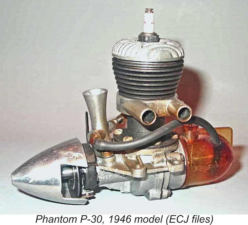
At the top, the cylinder head was a heavily-finned aluminium alloy die-casting which was centrally drilled and tapped to accept a ¼-32 Champion V2 spark plug. It's worth noting that the use of a ¼-32 plug on this size of engine was actually somewhat unusual at the time - most mid-sized and larger engines still used 3/8-24 plugs during the pre-WW2 years. The head was secured to the cylinder with six short machine screws which engaged with tapped holes in the upper cylinder flange. The blued steel cylinder with integrally-formed cooling fins now extended down below the exhaust ports to the upper crankcase deck, being secured by six machine screws. With the crankcase/cylinder design now used, an integrally-cast exhaust stack could no longer be featured. Instead, a separate clamped-on die-cast light alloy stack of rectangular section was employed. The twin bypass passages were of the internal flute type. They were radially spaced about 70 degrees apart opposite the exhaust and were formed in a unique way, being pressed out as “bulges” from the interior of the bore, presumably prior to the actual finishing of the bore itself. Given their near vertical release of The die-cast main crankcase was formed in two separate halves which were joined along a transverse vertical split and secured by four machine screws inserted from the rear. The front casting incorporated the bronze-bushed main bearing in unit, while the rear portion incorporated the backplate. Presumably the location deck for the cylinder was machined after the two crankcase halves had been assembled. The stamped steel piston drove the one-piece steel crankshaft through a cast alloy connecting rod. The steel gudgeon (wrist) pin was fitted with brass end pads. A word of caution to conservation-minded owners – if you ever dismantle one of these units, make sure that these pads are present before reassembly. The crankshaft ran in a bronze bushing. Crankshaft front rotary valve (FRV) induction was retained, with the induction port in the counterbalanced one-piece steel crankshaft being a milled rectangular aperture which gave more rapid opening and closing of the induction system than would be the case with a simple round hole. The former use of an updraft intake was abandoned in favour of a downdraft arrangement using a separate bolt-on venturi of considerable length. The fuel control system was unusual, consisting of two components - a screw-in boss for the needle and a fuel pickup tube set at right angles and discharging through a surface jet system. The boss for the needle valve was horizontally aligned rearward at 45 degrees to the engine's axis, placing the plastic needle control knob well aft of the prop disc. The externally-threaded needle was tensioned by a gland nut - a quality touch normally seen only on racing models. The timer design was considerably more sophisticated than that used in the earlier Atwood Phantoms, being an automotive-style unit of the type more commonly seen on racing engines of the period. The prop driver had an unusually large diameter. It was locked to the shaft either through the used of splines or by being provided with a square-section central aperture which engaged with a short square protrusion at the front of the main journal.
Finally, a completely new tank of translucent plastic material was mounted on the backplate, being secured by a long machine screw. A noteworthy feature was the use of a fuel line which was formed from copper tubing and attached to the spraybar at its delivery end by a short length of rubber tubing. It will be clear from the above description that the original version of the Phantom P-30 owed very little to the earlier Atwood Phantom models. These original examples of the engine bear serial numbers having an “A” prefix. The only serial numbers from this series of which I'm currently aware are A1390 and A1829. I’d be most grateful for any further reader contributions to the cause!
This unhappy event doesn’t seem to have resulted in the immediate cessation of production of the P-30. On the contrary, the engine was the focus of the regular “Logging the Motor Market” feature in the September 1942 issue of “Flying Aces” magazine, as reproduced at the left. The article clearly implied that the P-30 remained available at the time of publication. It went further, suggesting that certain manufacturers (presumably including Phantom Motors) had foreseen America’s eventual involvement in WW2 and the consequent material shortages, hence stocking up on the more critical raw materials in advance of the conflict. Even so, the writer clearly foresaw a looming powerplant shortage, advising The diversion of manufacturing capacity to war production greatly inhibited the ability of most manufacturers to maintain adequate production levels – many didn’t even try to do so. Phantom Motors seem to have carried on for a while, although the drying-up of supplies of good quality casting-grade aluminium alloy forced them to switch to a different grade of casting alloy having a high lead and zinc content. Unfortunately, this material is chronically afflicted with the condition known as "zinc pest", which results in the irreversible deterioration of items cast from such material. While the resulting engines were identical to the original models in design terms, they were considerably heavier, also appearing somewhat darker in colour. A case can be made that they constitute the second variant of the Phantom P-30, although the differences are confined to the material specification of the castings. These variants generally bear serial numbers having an “AA” prefix. The only serial numbers in this series of which I am aware are AA197, AA978 and AA2435. The overlap between the A and AA prefix numbers makes it appear certain that the sequence was re-started at AA1 when the casting material was changed and that at least 2500 examples of the heavy-case engines were produced in addition to perhaps 2,000 examples of the original variant. The Post-WW2 Phantom P-30 Models It’s unclear how long production of the pre-war Phantom P-30’s was maintained. Reading between the lines, it appears that at some point the Automatic Screw Machine Company abandoned model engine manufacture, retooling instead for war production. This impression is based upon the fact that they were evidently not in a position to take immediate advantage of the US War Production Board’s mid-1944 decision to permit the release of sufficient material to allow the production of model engines to resume, albeit on a still-restricted basis. This decision An article on this matter appeared in the October 1944 issue of “Air Trails Pictorial” under the title “Engines Return!”. The writer cited eight well-known model engine manufacturers as intending to take immediate advantage of this relaxation of restrictions. Phantom Motors was not among their number. Indeed, it was not until 1946 that Phantom Motors were to make a reappearance as model engine manufacturers. When they did so, they began by offering a revised version of their pre-WW2 P-30 design. They did so under the name Phantom Motors Distributing Co. This was simply a re-named Phantom subsidiary of the Automatic Screw Machine Company, which was identified in small print in the advertisements as the actual manufacturer of the engines. A representative advertisement is reproduced below at the right, this one dating from December 1946.
The revised exhaust system took the form of a new die-casting which incorporated dual exhaust pipes, one each for the two fore-and-aft exhaust ports. This component was once again a clamp-on design. The twin exhaust pipes gave these engines a quite unique appearance. Other changes included the provision of a larger and more complex timer which was machined from a casting. The carburettor design was also changed - a conventional straight-through transverse spraybar was now used in place of the former two-piece arrangement with separate fuel nipple and needle boss components set at right angles to each other. The former copper fuel line was no longer featured, flexible tubing being employed instead. The routing of this tubing was facilitated by the provision of a rearward bend at the fuel pickup end of the spraybar. In addition, a stiffening “rib” was added along each side of the transparent plastic tank. The large-diameter spinner continued to be featured, although use was made of both spun and die-cast components. The serial numbers of these variants featured the letters “B” or “BA” as prefixes. The differences between the engines bearing the two prefixes are unclear – perhaps the BA examples featured residual examples of the heavier AA castings?!? I’m currently aware of engines of this type bearing the serial numbers BA231, B1609B, B1643, B2006B, BA2180B, B3013 and B3963. It appears that the sequence was started at BA1 and that at least 4,000 examples were made. The significance of the B suffix in nos. B1609B and B2006B is unknown.
In other respects, the engine was unchanged. The serial numbers of these variants bore an N prefix, although it appears that the N prefix may have been dropped near the end of production. I’m aware of engines of this type bearing the serial numbers N756X, N798, N1156X, N2006, N2483, N2506, N2921, N3678, N4415, N4766X and 5170X (missing the N). The overlap between the B and N prefixed numbers seems to confirm that the numerical sequence was restarted at 001 for the N series.
This variant of the P-30 was the subject of a review which appeared in “Air Trails” magazine, as reproduced at the left. As usual with the reviews in this publication, the main focus was on the engine’s design and construction, the real highlight being the excellent cut-away drawing which accompanied the article. Some very limited performance data did appear. The reviewer reported speeds of 6,700 RPM with a Flo-Torque 12 in. dia. “low pitch” prop, 6,800 RPM with a Hi-Thrust 10 in. dia. “high pitch” prop and 7,500 RPM with a Ritz 11 in. dia. “medium pitch” airscrew. These figures are far too vague to provide any useful performance data. In his article entitled “Model Motors for 1948” which appeared in the January 1948 issue of “Model Airplane News” (MAN), Edward G. Ingram was a little more specific, quoting a recommended airscrew size of 11x8, which he claimed that the engine would turn at 8,200 RPM - perhaps a little optimistic?!? The manufacturers themselves rated the engine at 1/5 HP, but this appears to have been more of a classification rating than an actual performance claim - many manufacturers made similar claims. The November 1947 introduction of Ray Arden’s commercial miniature glow-plug sent a major shock-wave throughout the model engine manufacturing community. Manufacturer reactions varied – some carried on for a while with what they had; some others immediately embraced the new technology and set to work developing their own glow-plug designs; and others simply quit the field. Phantom Motors seems to have been among the latter – there’s no evidence that they ever developed a glow-plug version of, or a replacement for, the now-venerable P-30. They either folded or went on to other work. So ended a ten-year involvement with model engines on the part of Phantom Motors, going back to the Bill Atwood era. Their final product, the P-30, had served American modellers well for six years, but it was evidently time for company owner Arthur Andersen and his colleagues to move on. I have no information regarding their further activities. The Phantom P-30 on Test
To get the ball rolling, I set the engine up in the test stand with a 12x5 Zinger wood prop fitted. A check of the timer function using a continuity tester confirmed that the timer was working perfectly, also allowing me to position the timer at an appropriate setting for starting with the points opening about 10 degrees before top dead centre. I used a previously-tested Champion V2 spark plug, with the sparks being provided by one of my super-dependable Larry Davidson SSIGNCO units. The fuel was my usual 75/25 mix of white gas (Coleman Camp Fuel) and S.A.E. 60 mineral oil (AeroShell 120) - an appropriate "period" brew.
I subsequently found that even the fuel in the intake wasn't strictly necessary. All that was required for a start was a few choked flicks followed by a few more to distribute the fuel through the engine. Then switch on the ignition, and starting was almost immediate thereafter. Once running, the Phantom performed flawlessly. Respose to both controls was all that could be desired, making the establishment of the optimum setting extremely straightforward. Fuel consumption appeared to be quite modest - the engine seemed to run forever on a full back tank. Running was smooth and steady, with no tendency to hunt or sag. Vibration levels were well within acceptable boundaries. There was no evidence of any timer shortcomings up to the highest speeds tested. The following data were collected during the test.
The above data imply a level of performance which I see as being if anything a little above average for a .29 cuin. non-racing sparkie of this vintage running on white gas. The engine developed around 0.196 BHP @ 7,400 RPM, thus fully supporting the manufacturer's rated output claim of 1/5 BHP. It showed no signs of mechanical stress at any point, also handling superbly. Overall, I have to say that I was quite impressed!
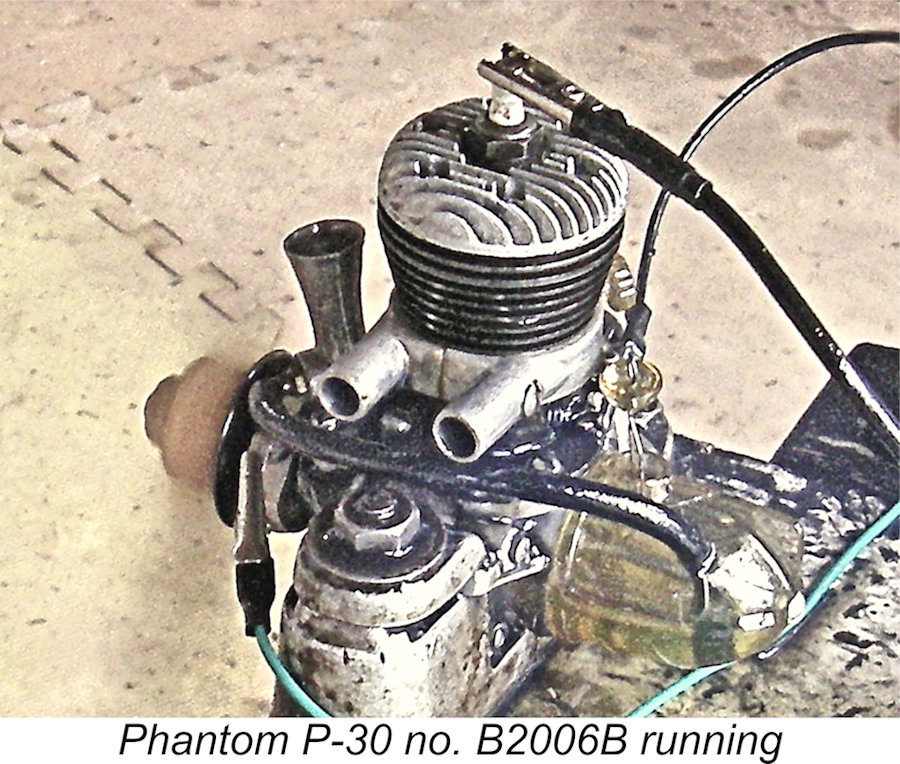
While this article was in preparation, and subsequent to the testing reported above, I had the opportunity to test another example of the P-30. This was an example of the third variant with the clamped-on die-cast twin exhaust pipes. It bore the serial number B2006B. On test, this example started just as easily as its fourth model predecessor in the test stand, the one difference being that it was far more sensitive to the needle setting. Presumably this was down to differences in the respective needle tapers. It ran equally smoothly once set, turning all of the same props within 100 RPM of the previously-tested fourth model. For all practical purposes, the This second test did provide an insight into the possible reason for the switch from clamped-on die-cast exhaust pipes to brazed-on components. The leakage of exhaust gases and residues from the clamps at the exhaust locations was pretty chronic. A substantial proportion of the exhaust residues never made it out through the pipes, ending up instead inside the model - you can see this in the accompanying image, which shows the significant oil deposits which quickly built up directly behind the engine. This rather defeated the presumed purpose of the twin pipes, which was to keep exhaust residues clear of the model's fuselage. The brazed-on pipes were presumably a response to this issue, and a completely effective one at that. Conclusion I hope that I've managed to convince you a) that Bill Atwood had nothing to do with the Phantom P-30; and b) that the actual designer Arthur Andersen came up with a design which, although somewhat more complex than many competing models, nonetheless represented real value to the power modellers of the early post-WW2 era. Andersen came up with a fine-handling unit which delivered a more than acceptable level of sport-flying performance in the context of its era and displacement. He also manufactured the engine to a very good standard. The P-30 appears to have been manufactured in quite substantial numbers. A considerable proportion of these engines have evidently survived down through the years. Consequently, examples in varying states of preservation appear fairly regularly on eBay and elsewhere at not-unreasonable prices. Anyone wishing to give one a try should be able to find a functional example with a little patience. And anyone who does so will be well rewarded - the P-30 is a class act! ___________________________ Article © Adrian C. Duncan, Coquitlam, British Columbia, Canada First published July 2023
|
||
 Here I’ll take a look at a well-known and highly respected American spark ignition engine whose production life spanned the WW2 years – the 0.297 cuin. Phantom P-30 from Los Angeles, California. This engine has been widely and incorrectly associated with the iconic model engine designer and manufacturer Bill Atwood. Time to set the record straight once and for all!
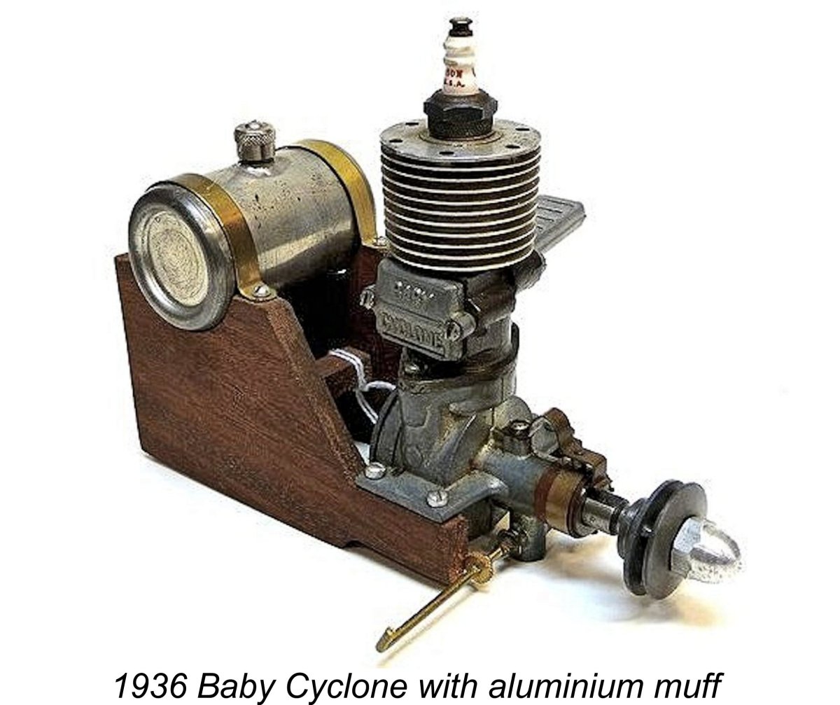 The commercial rendition of Bill’s engine was christened the Baby Cyclone, a name very familiar to latter-day connoisseurs of classic spark ignition powerplants. Although ostensibly manufactured at Moseley’s Glendale plant, in reality much of the machining work was actually carried out under contract by the Automatic Screw Machine Company on Gage Avenue in Los Angeles. However, the fitting, assembly, testing and packaging were carried out at Moseley’s facility along with a limited amount of machining.
 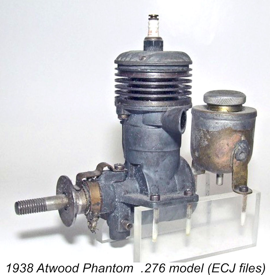 A new subsidiary entity called Phantom Motors, Hi–Speed Division was established by the company. This was the origin of the Phantom name and its association with Bill Atwood. Bill immediately proceeded to design and develop the very successful Phantom line of Bullet, Hi-Speed and Torpedo engines for his new employers. These were the first engines to bear the Phantom name. It’s important to note that the Phantom name was that of a company rather than a model designation for a series of Bill Atwood designs.
 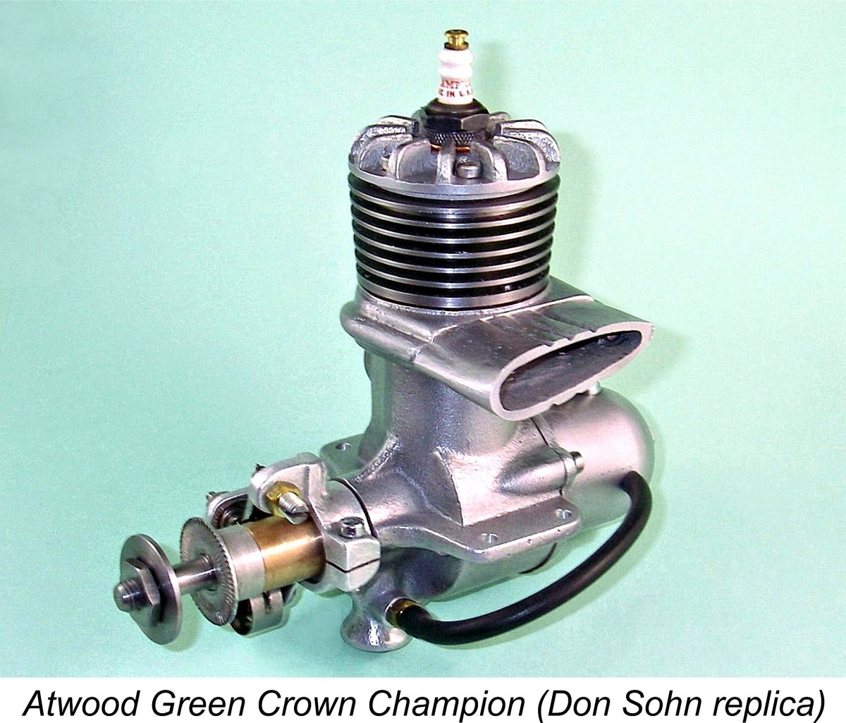 role with respect to this company’s manufacturing activities is now unclear – it may have simply represented a new name for the products of his own workshop, or it may represent a completely different manufacturer working in association with Bill. Regardless, it was only at this point that he began to apply the Atwood Crown Champion name to the engines.
 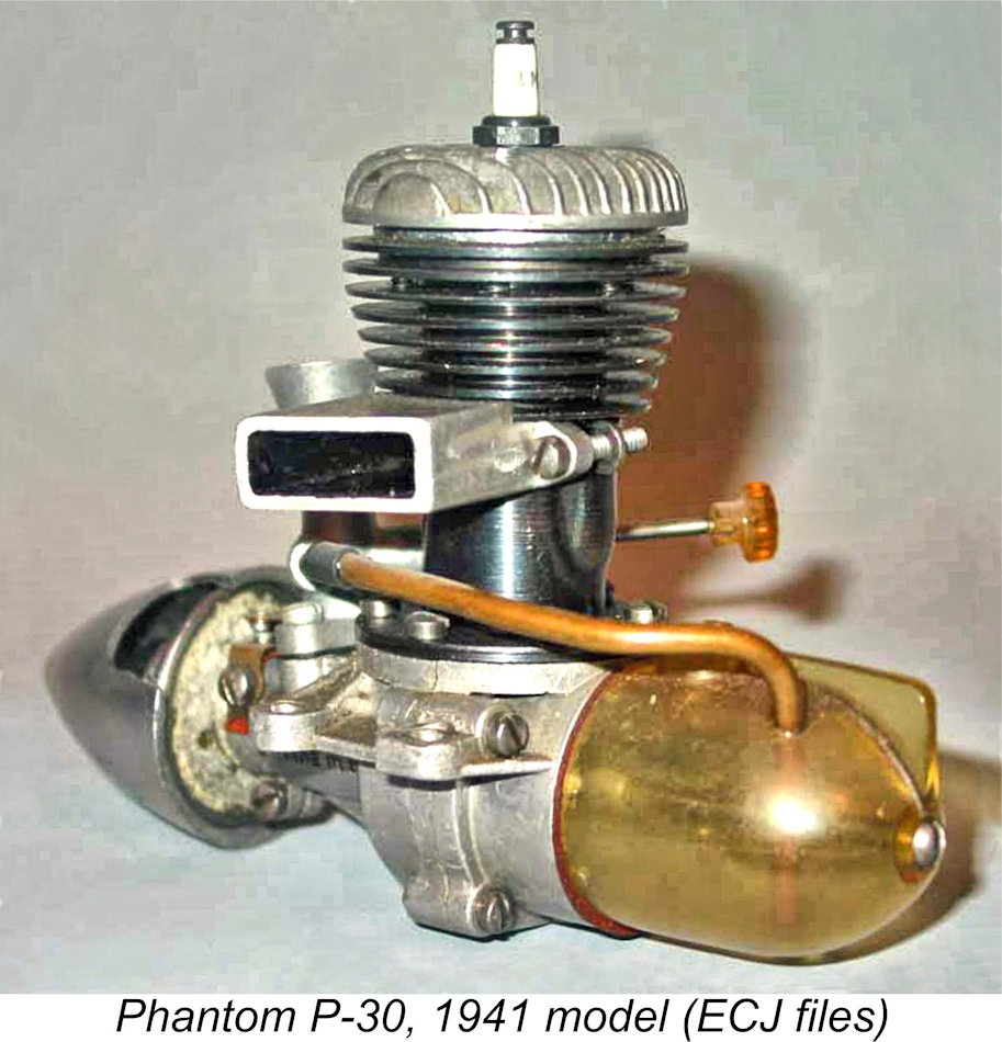 A few key design decisions were taken at the outset. First off, the displacement of the new model would be increased from the 0.276 cuin. of the earlier Atwood-designed Phantoms to a full 0.296 cuin. This step had already been taken with the 0.299 cuin. Hi Speed Torpedo of July 1939. Taking full advantage of the AMA Class B displacement limit, Andersen adopted bore and stroke dimensions of 0.710 in. (18.03 mm) and 0.750 in. (19.05 mm) respectively for a displacement of 0.297 cuin. (4.87 cc).
 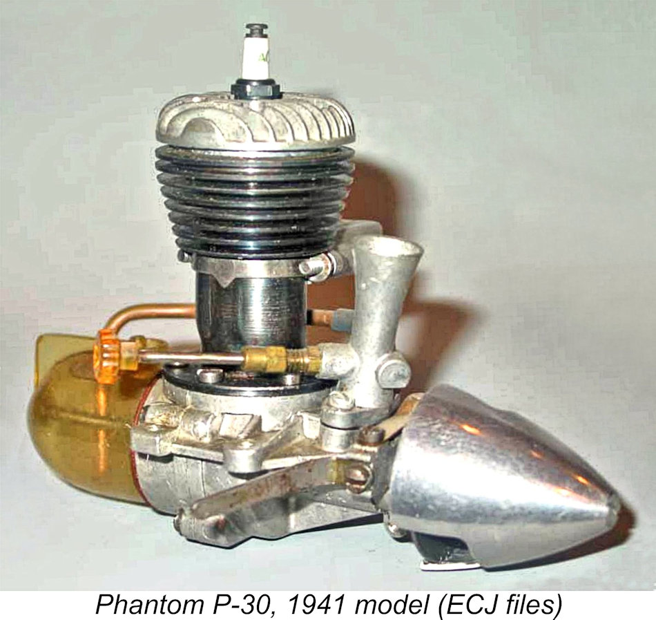 mixture into the cylinder, the designer felt comfortable in eliminating the piston baffle commonly seen on such engines. The passages were supplied with mixture at their lower ends through a pair of appropriately-located piston skirt ports.
 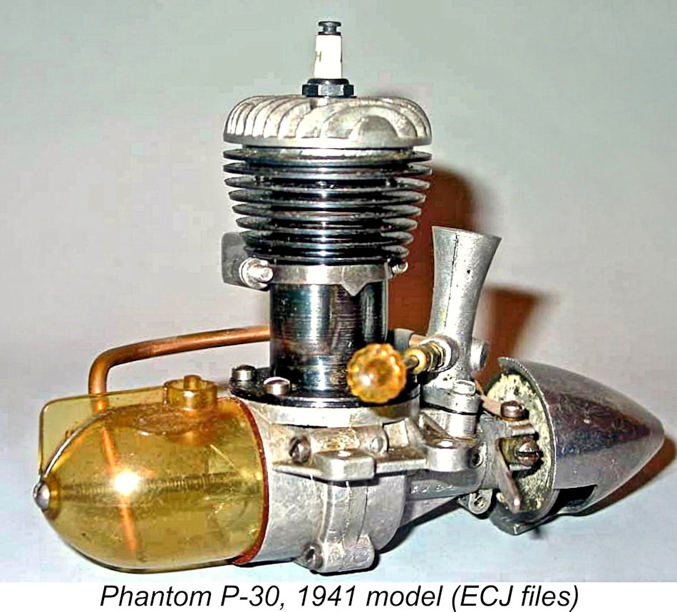 The appearance of the engine was strikingly enhanced through the provision of a large-diameter aluminium alloy spinner. This accessory was to be featured throughout the production life of the P-30 going all the way up to 1948. The prop was actually secured using a conventional nut and washer - the spinner was a strictly cosmetic addition which was secured by a 4-40 screw which engaged with a tapped hole at the forward end of the crankshaft.
 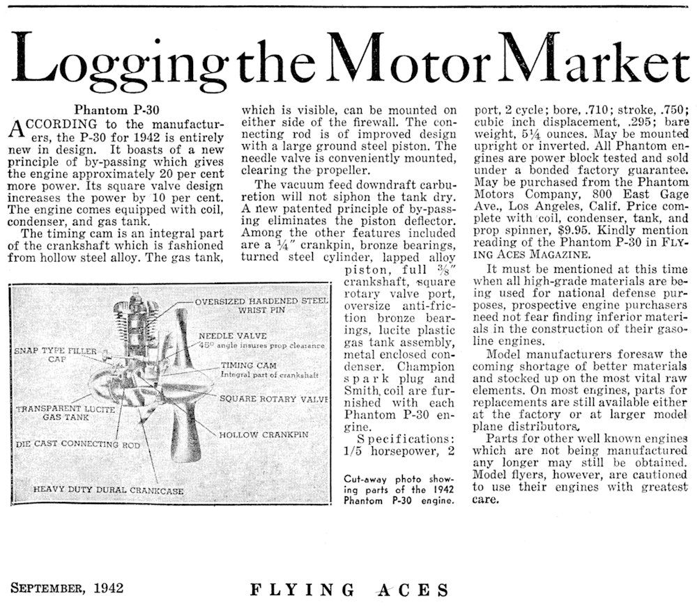 The original Phantom P-30 first appeared in October 1941. The timing could certainly have been better, because the USA was drawn into WW2 almost immediately by the Japanese attack on Pearl Harbour on December 7
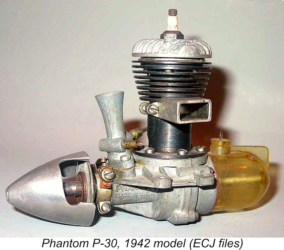
 was based largely upon the perceived value of aeromodelling in fostering interest in aviation among young Americans, thus promoting their future involvement in the military and manufacturing branches of full-sized aviation. Purchasers of new engines had to demonstrate an active involvement in aeronautical education.
 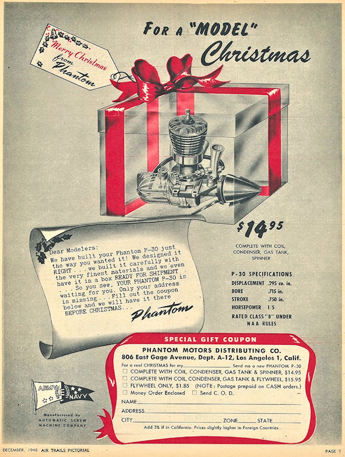 The most immediately obvious change was the re-arrangement of the cylinder porting. The design of the blued-steel cylinder had been significantly revised, with twin exhaust ports in a fore-and-aft configuration and twin pressed-out bypass flutes located opposite one another between them – in effect, the porting arrangement that was later to be made famous by Cox. The former clamped-on rectangular-section exhaust stack would clearly not work with this new configuration.
 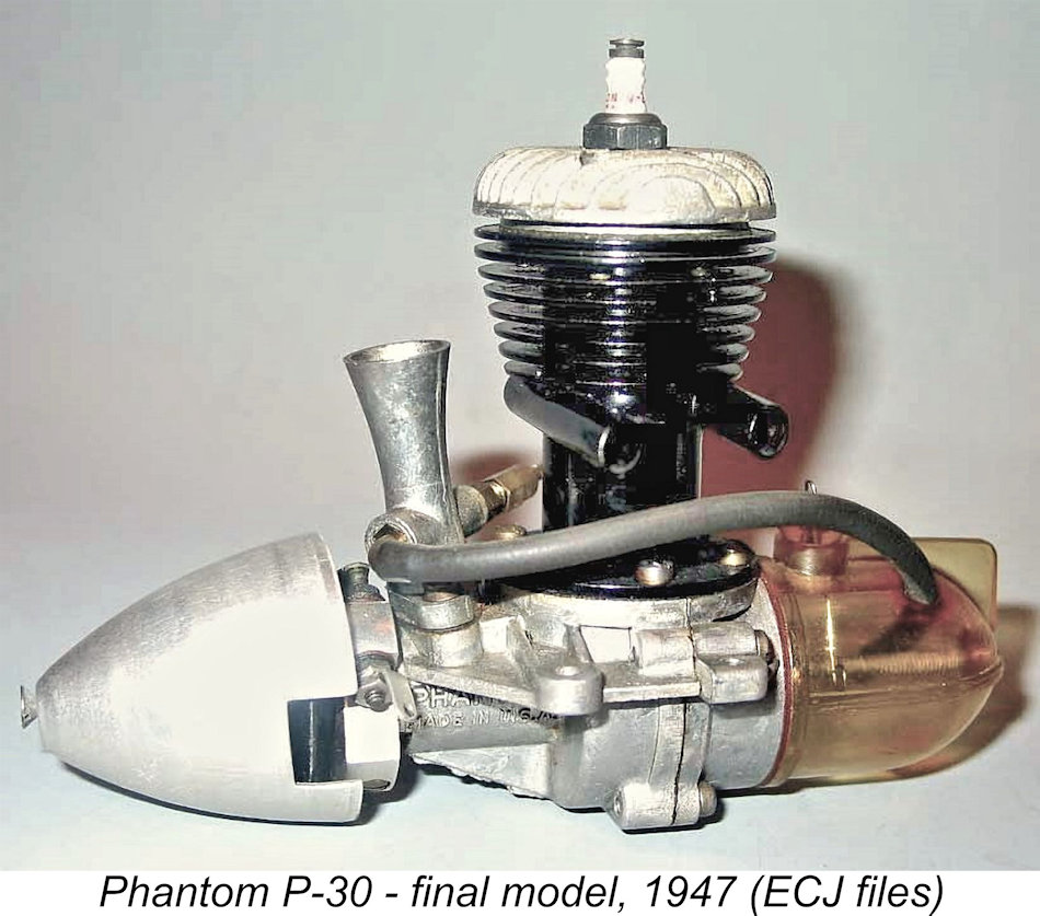 What was to be the final variant of the Phantom P-30 appeared in 1947. In functional design terms it was identical to the 1946 model, the changes being more of a detail nature than anything else. Most notably, the former clamp-on twin-pipe exhaust collector was discarded in favour of a pair of tubular exhaust pipes which were brazed in place over the exhaust ports. The cylinder was no longer blued, clearly reflecting the use of brazing in its construction. Instead, it was painted in heat-resistant glossy black paint, thus concealing any visible evidence of the brazing operations. The measured compression ratio of this variant was a perfectly reasonable 7 to 1.
 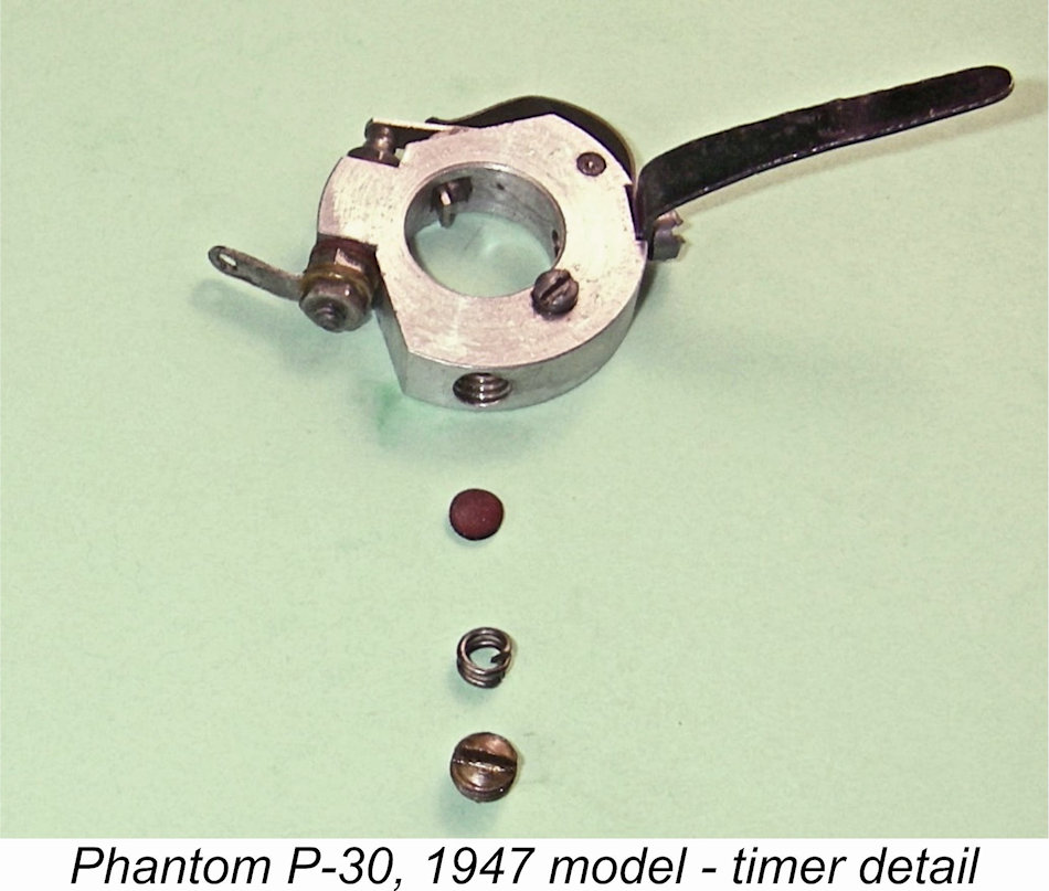 The timer was now machined from bar stock rather than being based on a casting. It featured a very elegant method of providing sufficient rotational resistance to maintain the setting while running. A tapped hole was provided at right angles to the timer axis, communicating with both the outer surface and the bronze bearing bushing. A non-metallic disc was inserted into this hole, followed by a very short coil spring and a slot-head grub screw. When tightened up, the non-metallic disc pressed against the bearing to provide the necessary friction to prevent rotation. The timer provided a dwell period (points closed) of around 50 degrees - quite appropriate for the kinds of speeds which might be anticipated from this engine.
 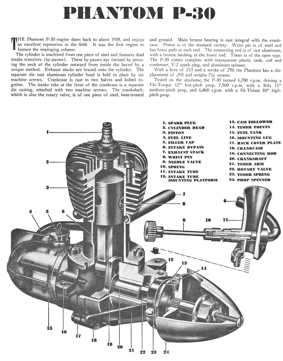 The addition of the X suffix to several of these numbers is a bit obscure. Tim Dannels reckoned that it probably indicated a replacement case with the original serial number transferred, but the suffix is encountered more often than one would expect if that was the case. My example no. N1156X appears almost unused and free from any signs of damage, making it seem very unlikely that it ever required a replacement case. The mystery remains ..............
 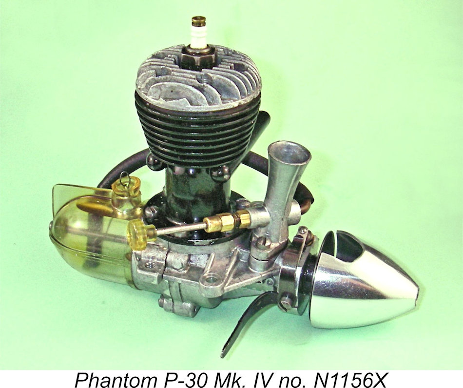 Thanks to the kind assistance of my friend and colleague Ted Smith of Australia, I had a nice example of the final variant of the P-30 on hand for testing. This unit bears the serial number N1156X. It is complete and original apart from having lost the large-diameter spinner with which all of these engines were supplied. The fitted replacement is a correctly-sized modern component which at least looks right! The engine appeared to be little used and was perfectly fitted, with excellent compression and freedom from slop in the bearings.
 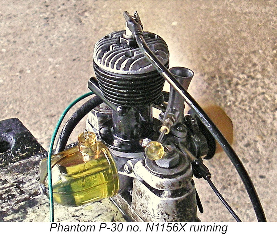 The two small-bore exhaust pipes presented a challenge when it came to administering a measured exhaust prime for the initial start. Instead, I tried a couple of choked flicks followed by a few drops of fuel down the intake venturi. After a bit of flicking to get some fuel up into the cylinder, the engine began to fire, followed quite quickly thereafter by the initial start. The four turns at which I had set the needle by guesswork proved to be somewhat on the over-rich side, but the engine kept going regardless, giving me ample time to correct the setting.
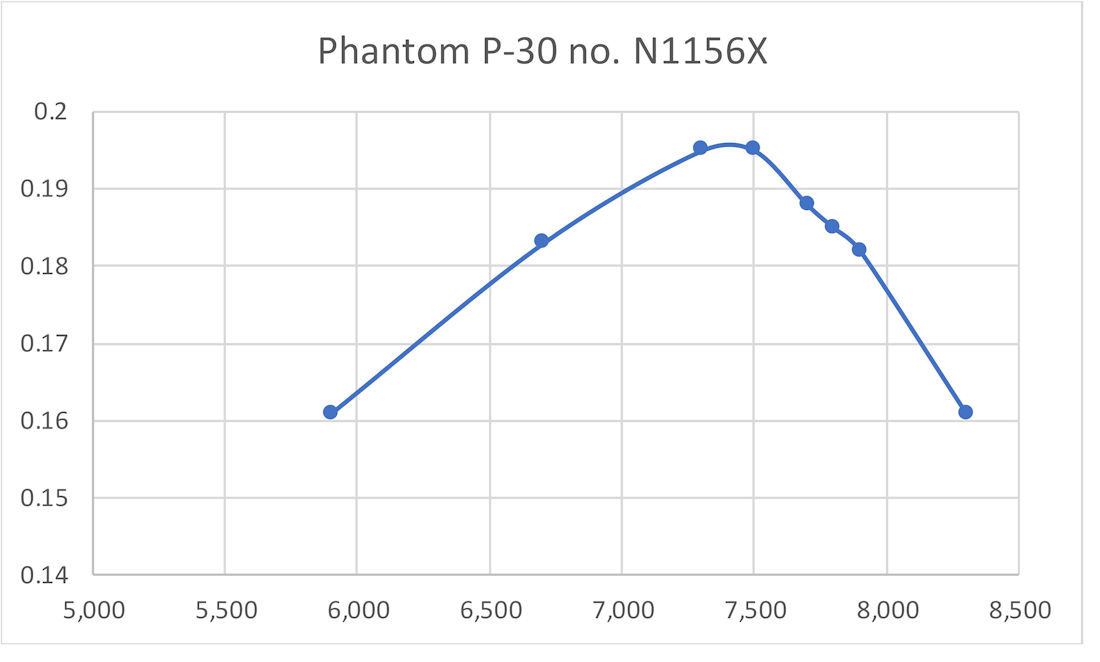
 One noteworthy point arising from the above data is the fact that I found little support for the figures quoted in the "Air Trails" test report apart from the figure obtained with a 10x8 prop, assuming that 8 in. would have been seen as "high pitch". Moreover, the figure of 8,200 RPM on an 11x8 airscrew quoted by Ed Ingram seems to belong in the realm of fantasy!
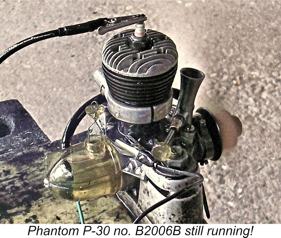
| |