
|
|
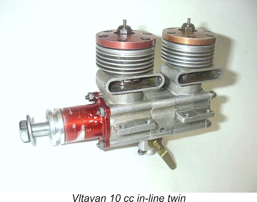
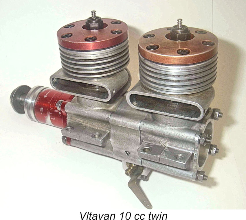
The “Vltavan” In-Line Twin
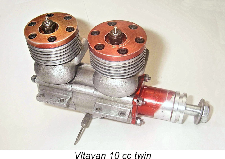
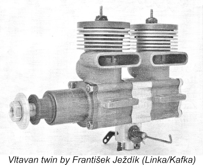
In this article I’ll describe one of the more functional examples of such an engine – the 10 cc Vltavan-based in-line glow-plug twin created by several constructors in Czechoslovakia (as Czechia was then known) using components of two examples apiece of the far better-known Vltavan 5 racing engine from Prague. These units are known to have been constructed by František Ježdík, M. Herber and possibly one or two others. The example which is available for discussion here came to me years ago in disassembled form in a trade. It was missing its piston rings, glow-plugs and carburettor spraybar, but otherwise appeared to be all complete. An earlier article about this interesting twin appeared in December 2007 on MEN, but I've learned a lot more about the origins of this unit since that time. Because MEN is now frozen, I have no choice other than to publish this substantially-revised article on my own website. Without further ado, I’ll get into a description of this very interesting exercise in model engineering. Description
It turns out that the easiest way to describe the Vltavan twin is to walk the reader through the processes involved in its construction. The key steps that had to be taken in order to create this engine were as follows. The central valve section that is the heart of the layout was clearly produced first. This was evidently shaped from barstock. The work was carried out very competently, with a finish and cross-section that were carefully crafted to match those of the two cases. Once this was completed, the bearing bushing had to be produced and fitted. I reckon that this was done before the unit was fully machined, with the bearing being finished after installation to allow for any distortion during fitting. It’s difficult to be sure of the material of this bushing since I can’t dismantle the unit for inspection, but it appears to be cast iron.
After that, the central crankshaft itself had to be fitted and assembled by joining its two pieces. The web at the rear is a dead ringer for a standard Vltavan 5 crankweb, while the front "web" disc is just that - a plain disc with an integral "crankpin" of The central crankshaft’s main journal is integral with the rear crankweb and includes the induction ports for both fore and aft cases. The diameter of the individual central holes in the shaft which fed the front and rear cases alternately is 6 mm, while the main journal diameter appears to be 11 mm (I can’t separate the components to check accurately, but this is close).
Next, the rear portion of the central crankshaft had to be very accurately fitted to the central bearing. Incidentally, this fit is of the very highest order - with the unit bone dry there’s no detectable trace whatsoever of any radial play, yet with a little machine oil the bearing spins as freely as one could wish. Overall, the quality of workmanship is right up there! After the fitting of the rear portion of the central crankshaft into the bearing, the two pieces of that crankshaft had to be mated. This was an irreversible step because once done, the central shaft section was assembled for keeps. Accordingly, everything had to be right! The front disc was force-fitted onto a shoulder or a very shallow taper on the front of the central shaft. To ensure that it remained correctly positioned at 180 deg. to the rear web, this disc was then staked in place with a pin which was press-fitted into a hole drilled at the junction between the two components. You can see this very clearly in the photo of the front web which was included earlier.
A ba Once the basic assembly was complete, the lower faces of the bearers had to be milled at a single setting to ensure that the front and rear sets of mounting lugs were in perfect alignment. This appears to have been carried out to a very high standard of accuracy on my example. The rest of it was a straightforward assembly job using standard Vltavan 5 cc components. The provision of an R/C carburetor would have presented no difficulties. I don’t know if the unit which came with the engine was custom-made or was outsourced, nor does it matter much. I suspect that it was custom-made given the unusually large diameter of the induction hole into which it had to fit. Overall, I’m impressed with both the design and execution of this project. A very talented brain was applied to both design and construction aspects of the engine. However, it should be apparent from the above summary that the amount of extremely precise machining required to produce this engine would have precluded its manufacture in commercial quantities. It must surely have fallen into the “labour of love” category.
The observant reader may have noticed the presence of a row of four holes drilled transversely across the centre lines of the two exhaust stacks. These holes are clearly intended to accomodate a long rod or bolt passing transversely fore and aft across the stacks. It seems almost certain that this rod or bolt somehow served the function of securing a muffler to the engine. If the noise level produced by one of the original Vltavan 5 racing units is anything to go by, this twin would have urgently needed such a fitting if it was to see any use on the flying field! Reassembly
First up, a general comment regarding the provenance of this engine. The two heads were still both tapped for the original 1950’s vintage Czech plugs which used a The first step in the reassembly process was to inspect the front end components and assemble them as a unit. The front end of the Vltavan twin is essentially identical to that of the original single-cylinder Vltavan 5, the one departure being the addition of the previously-illustrated small hole drilled axially into the crankpin. This hole accepts the reduced-diameter "crankpin" through which the rear shaft transmits its torque to the front end. All of the components proved to be in first-class operating condition.
I’ve noted previously that the required standard of accuracy of manufacture of the basic components was very high given the complete lack of "give" in the assembly. In fact, it turned out that the standard attained was so high that the two shafts could be presented to each other through either of the two cases individually with the exhaust stacks on either side - the fits of the respective spigots on the bearing units was such that perfect concentricity was achieved in any configuration. However, the same could not be said of the fits of the two cases and the centre section when the four 3 mm dia. silver steel studs were inserted. In some configurations the holes in the various components did not quite line up with sufficient accuracy. The errors were small, but they were there. Quite forgivable really, when you consider the length of the overall passages involved and the closeness of the fit around the studs.
I tried various combinations and found that if I used case number 2253 as the front case with the exhaust on the left as originally featured in the Vltavan 5 units, the alignment was perfect. In fact, the studs could be slid straight through both the case and the central unit with minimal resistance. Case number 3898 could then be fitted onto the studs from the rear with only a little resistance apart from the tight plug fit of the spigot into the case as mentioned earlier. I decided that this would be the assembly configuration of the engine for the purposes of this rebuild.
To test this, I first assembled the front-end components as shown to confirm that the two shafts were perfectly aligned. This was A-OK - not so much as a hint of binding, and the two shafts rotated perfectly freely together. A gold star to the constructor! I then removed the front housing and dropped a ringless piston into the cylinder. Upon fitting the front end once more, everything still rotated absolutely freely. No trace of binding and no indication of contact between the piston skirt and the studs at BDC.
The first issue to be dealt with was the fact that the two rods (which I was careful to keep associated with the same pistons and gudgeon pins in the same configuration all along) were extremely accurately fitted to the crankpins. This would be fine except for the fact that the rear crankpin (the one on the rotary valve shaft) was fractionally larger in diameter than its counterpart on the front shaft! The accuracy of fitting was such that only one of the two rod big ends would fit onto the rear crank-pin! This pretty much decided the issue of which rod went where. In both cases, the fits are quite beyond reproach - I’ve never seen better. So how did the pistons that were associated with these rods match up to the cylinder liners which were fitted to the cases in which they would now have to operate (unless I switched pistons on their rods)? As it happens, very well indeed!! I could only find at most a diametric variation of about two-tenths of a thou Accordingly, I went ahead and assembled the two cases with the appropriate piston/rod assemblies for the respective crankpins, checking that the aluminum end pads on the gudgeon pins remained securely in place. All was well – the resulting assembly turned over with minimal friction (no ring drag, of course) and no trace of binding at any point. I could observe the clearance between the piston skirt and the assembly studs in the rear case with the backplate off, and confirmed that the small chamfers in the piston skirts were indeed necessary to prevent contact. With the chamfers added, clearance is perfectly adequate. Greatly encouraged by all of this, I went ahead and tried the backplate for fit. This definitely did fit best in one configuration with the "X" located on top - in that orientation, it slipped right over the four studs. All other positions gave a less-than-smooth fit. Note that I didn’t use gaskets at any point. There seemed to be no purpose to be served in doing so, given that all mating surfaces were finely machined and the spigots were such a close fit in their respective cases. I now had the engine basically together. The only missing bits now were the two heads and the carburetor. I added the nuts and lock-washers at each end of the four studs, only tightening them minimally at this stage since the engine had to come apart again to fit the rings. Then I added the cylinder heads, which I had previously lapped very lightly onto their respective cylinders. The Vltavan 5 doesn’t use a head gasket and I saw no reason to do otherwise for the twin. Once again, I didn’t tighten them fully at this stage.
Incidentally, I’m now completely convinced that this carburettor is a custom-made item constructed specifically for this project. The oversized mounting spigot would be way over the top for any conventional motor, while the slot in the base of the unit exactly matches the “slot” in the bearing sleeve through which the shaft breaks through into the induction to provide the correct timing. The fit too is impressive - a slightly tight but very smooth plug fit. The carburettor is yet another testament to the skill of the maker – it’s really very well made and fitted indeed. The constructor went to a lot of trouble to create this component. The small 3 mm set-screw which retains the carb was still with the engine, so on went the carb, and there it Having confirmed that the components would indeed go together to create a useable engine, my final step was to order a set of new rings from Frank Bowman. After they arrived, I dismantled the engine solely for the purpose of fitting the rings, being very careful to keep everything in the correct order and orientation. Upon re-assembly, the engine turned over just as freely as before apart from the expected ring drag. After tightening everything down and with plugs fitted, compression in both cylinders was more than adequate and would doubtless improve with some running time to bed in the rings. Base pumping action from both cases also appeared to be excellent. Another restoration project complete, and a very interesting post-script to the Vltavan story! The Vltavan Twin on Test
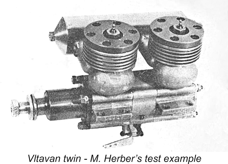
Herber had successfully completed his own example of the engine, using the components of two reportedly well-used examples of the original The attached elevation drawing extracted from that article may help to clarify some of the earlier description. The numbers with location arrows relate to the numbers assigned to the various components in the text of Herbert's construction article. Most fortuitously, Herber actually conducted a bench test of his example of the engine following its successful completion. I haven't plucked up the courage to try my own example, so the data reported by Herber will have to do for now. Since this is the sole published test of the engine that we're ever likely to see, I thought that it was well worth publishing here in full With a few editorial changes in the order in which the data is presented, Herbert's text translates more or less to the following: "The engine was tested using a straight methanol/castor oil fuel. Further testing using a fuel containing 5% nitromethane showed no measurable improvement in performance. The engine was also tested with a silencer (designed by V. Wiesgerber). With a significant reduction in the noise level, no significant decrease in revolutions was recorded. (We will post details of the silencer later). The following speeds were achieved during the test: Tornado Nylon 10x4 (254x101) - 12,000 RPM Tornado Nylon 11x6 (280x152) - 8,400 RPM Kavan laminated 11x7¾ (280x197) - 8,000 RPM The engine was found to throttle very well. The reliable idle with the Tornado Nylon 10x4 propeller was 2,500 RPM. The engine's reaction to changes in the throttle setting was admirably rapid. Its operation, especially when revs were changed quickly, was very reminiscent of the well-known and pleasant "burble" of a two-cylinder motorcycle, for example the Jawa 350 or BMW. The engine does not seem to want to quit!"
While by no means definitive, these figures suggest that the Vltavan in-line twin fell well short of matching the levels of performance of contemporary single-cylinder 10 cc R/C glow-plug units. Indeed, its output evidently didn't quite match reported figures for the Vltavan 5 single-cylinder model on which it was based, although it did develop useful power at substantially lower revs. Moreover, the twin weighed quite a bit more than most of the alternatives of similar displacement, also posing something of a mounting challenge. It would appear that this very interesting creation may best be seen as a fascinating exercise in model engineering which would certainly have turned a few heads if it appeared on the flying field mounted in a model. Bragging rights assured! However, its airborne performance would have failed to approach that of a good contemporary single cylinder 10 cc R/C glow-plug motor, although it would certainly have flown a model quite capably. Conclusion
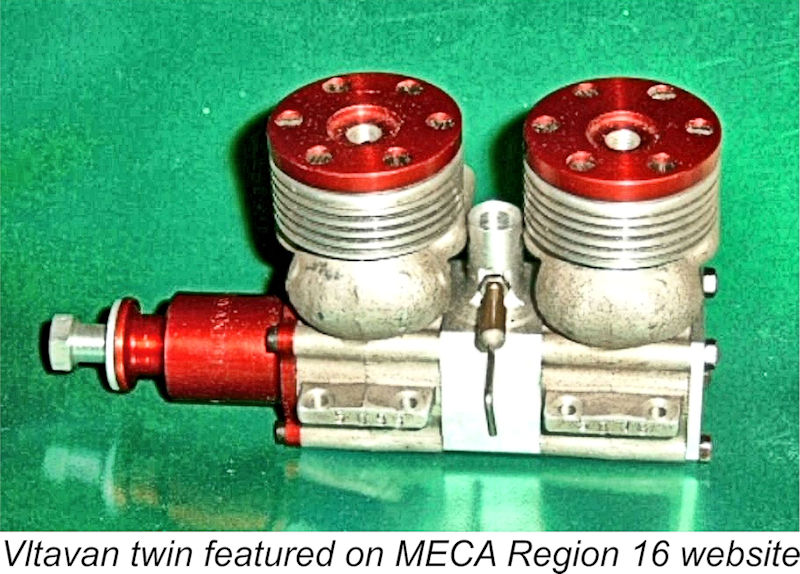
František Ježdík went on in 1965 to create at least one example of an opposed twin based on two Vltavan cases. Following these efforts, he designed and produced the well-known FIT engines. A very talented and dedicated individual! I have no knowledge of the further activities of M. Herber. At the time of writing (2023), I have certain knowledge of only five distinct examples of the Vltavan-based in-line twin-cylinder unit. One is my own example; another (above left) appeared some years ago on eBay; a third such unit is illustrated in the highly-recommended book “Czech The latter unit is particularly interesting in that it dispenses with the R/C throttle seen on all but one of the other examples. It features a relatively skinny intake tube which is small enough in external diameter to allow it to be located vertically in an upright orientation between the cylinders. This orientation would simplify the mounting of the engine to a considegrable extent. There may well have been a few more examples than those mentioned here, but the number created cannot have been very large. It would be very difficult to assemble a pair of "sacrificial" Vltavan 5 units today, besides which it would be irresponsible to destroy two such units to make one Vltavan twin. Accordingly, it's highly unlikely that this exercise will ever be repeated in the future. Still, a fascinating look at a skilled model engineer’s efforts to create a twin-cylinder engine of considerable technical merit! _________________________________ Article © Adrian C. Duncan, Coquitlam, British Columbia, Canada First published on MEN December 2007 This revised edition published March 2024 |
 You'll find a number of "Tinkerers' Special Twins" and other oddballs on the late Ron Chernich’s fascinating but now frozen “
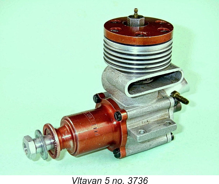 I’ve described the single-cylinder
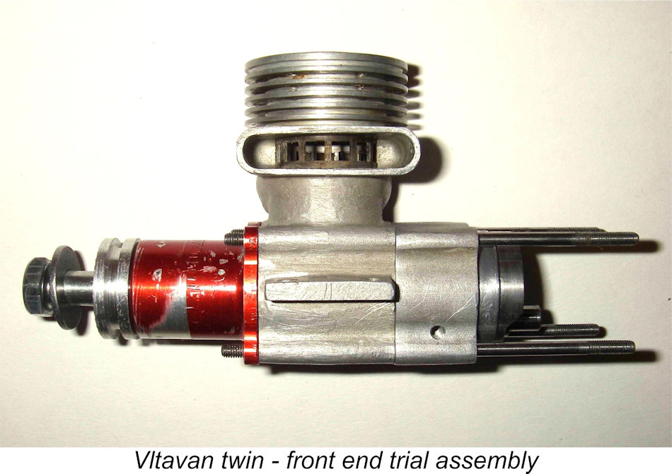
 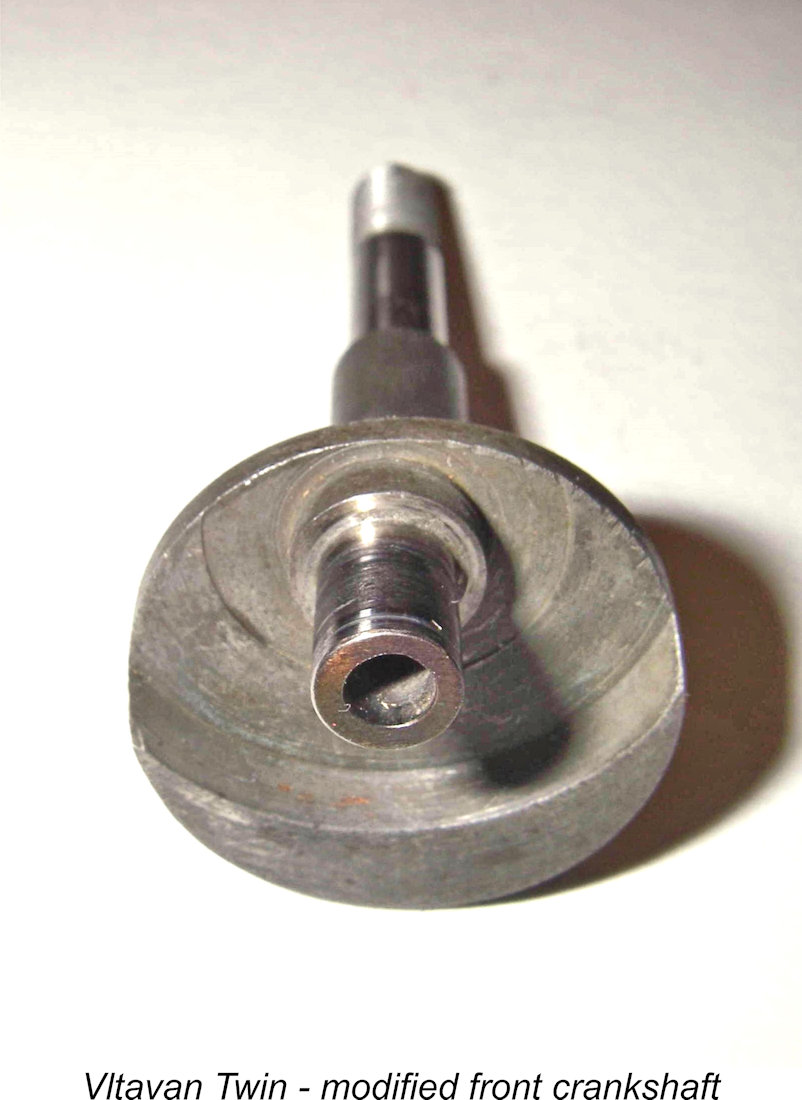 The central unit was then machined to fit the two cases. As the photos show, this was carried out to the very highest standards. The fit of the fore and aft spigots in their respective cases is tight - a very firm push-fit which takes some effort to assemble, with plenty of lubricant being applied to prevent galling. The multi-element crankshaft design employed is totally dependent upon the two crankshaft elements remaining in perfectly alignment, since the linkage between the two halves of the crankshaft (the small-diameter front pin on the central shaft plugging into a central hole added to the front crankpin) embodies absolutely no “give” whatsoever. The maker had clearly recognized this, accordingly making the components to the required high degree of accuracy, thus demonstrating his skill very clearly.
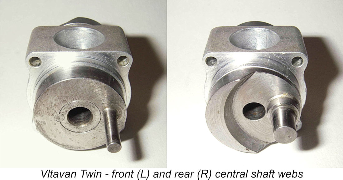
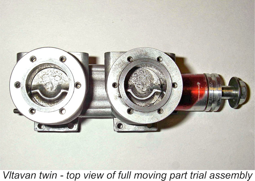
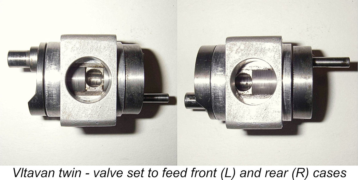 Since there’s no room for the carburettor between the two cylinders, the carburettor unit is located on the underside of the engine - a rather awkward location in my view. However, this is unquestionably the design orientation - the two induction ports in the central crankshaft journal are cut with the required timing for this configuration in mind. Induction period for both cylinders is a generous 180° - opening 30° after BDC and closing 30° after TDC. The closure is a lot earlier than that for the standard disc valve of the Vltavan 5 cc racing model, but this would be quite in order given the fact that the twin will certainly operate at well below racing-engine speeds. The large bearing diameter and the fact that the induction ports are milled square results in very rapid opening and closing of the induction ports - quite efficient. The attached views show this quite clearly.
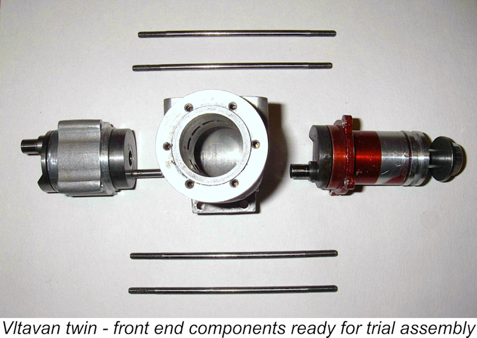
 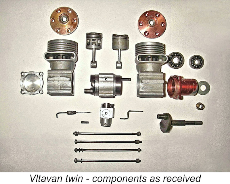 Next the two cases had to be assembled onto the central section, after which the set-up had to be drilled at the four corners to allow the insertion of the four long 3 mm dia. silver steel studs which hold the entire thing together. This too was a tricky job requiring great accuracy, a feat which was well within the capabilities of the constructor of this example. Very long drills of relatively small diameter tend to run off line very easily, but the maker avoided this very competently. Reliance was clearly placed upon the very tight plug fit of the spigot in the front case to maintain correct alignment of the two shafts. The role of the four studs is restricted to holding everything together longitudinally, while the rear case plays no role in affecting shaft alignment. The require four holes are drilled to a very high standard of accuracy, and there’s no radial play whatsoever between the cases when things are assembled.
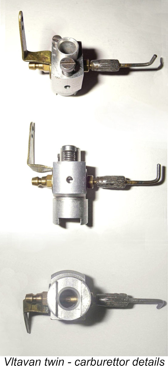
 By twin standards, I’d expect the resulting engine to run pretty well with its very efficient valve system and 180-degree timing. I’d also expect the resulting noise to be of a somewhat spectacular and perhaps rather aggravating character - this beast running flat out at 12,000 RPM would certainly send the peanut gallery running for cover!
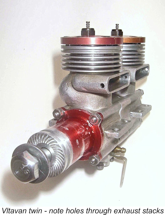
 Since the unit arrived disassembled, I had no idea how the two cases were originally oriented. As would be expected for Vltavans, one lug of each case bears a serial number – in this instance, 2253 and 3898. This more or less proves that the engine started out as two separate examples of the 5 cc Vltavan racing glow motor. Either could have been the front case and there are two ways of orienting the exhaust stacks as well – left or right. There was also no indication of which piston went with which cylinder liner. Even though piston/liner fit is less critical with ringed pistons, it's better to assemble with pistons already run into their bores, so careful measurement is indicated.
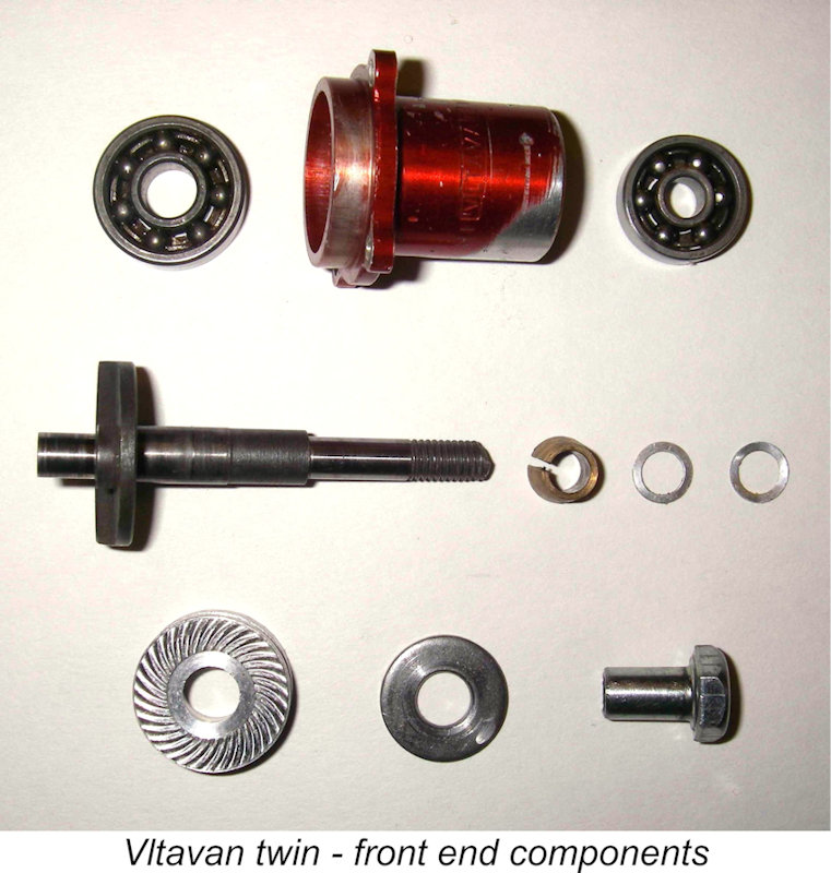
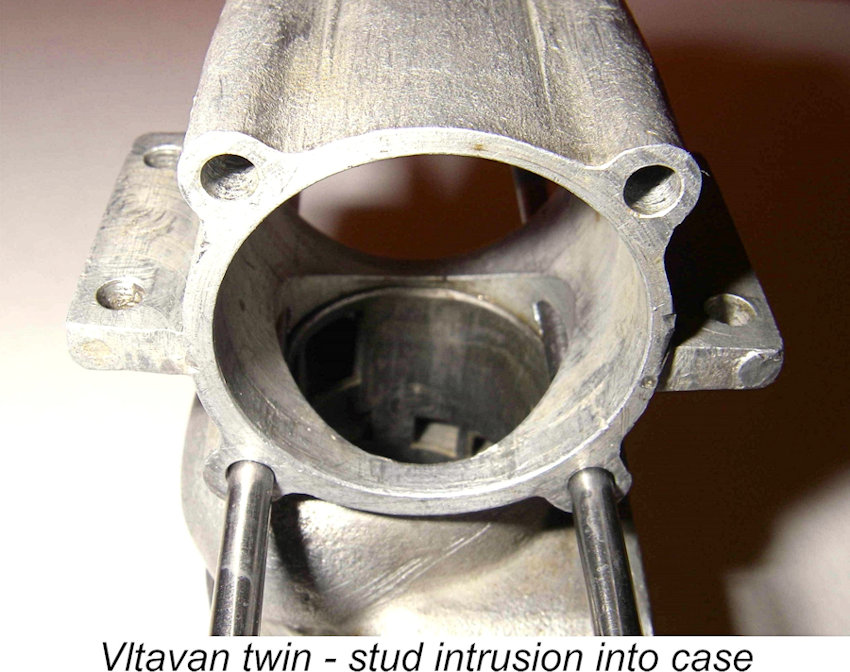 Before commencing the trial assembly of the engine, I took a close look at the passage of the studs through the cases. As can be seen in this photo, the studs unavoidably broke through into the case at its widest internal diameter. This was OK as far as it went, but the diameter of the studs actually intersected (albeit very minimally) with the projection of the bore. A quick test fitting of the pistons showed that the piston at Bottom Dead Centre (BDC) would undoubtedly intersect with the studs, thus creating a potential conflict.
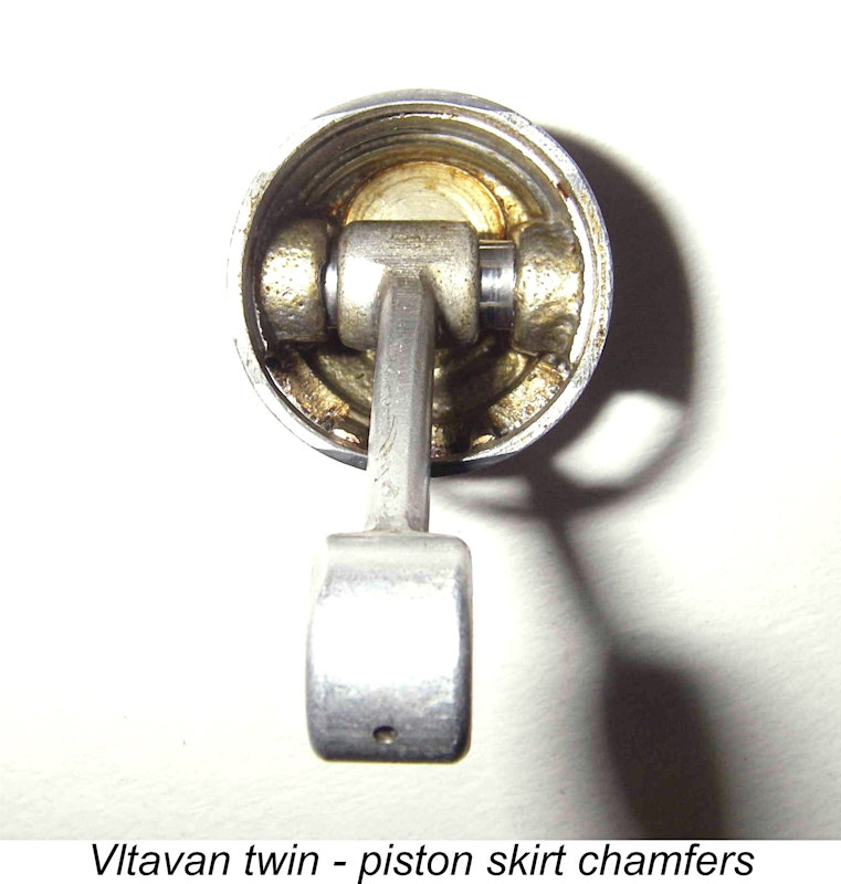 However, it seems that the constructor had noted this and taken steps to deal with it! Check out the image of the piston - note the small chamfers which have been neatly filed onto the lower edge of the piston skirt at both locations where it would otherwise intersect the studs (top and bottom of the skirt in the photo). Problem presumably solved!
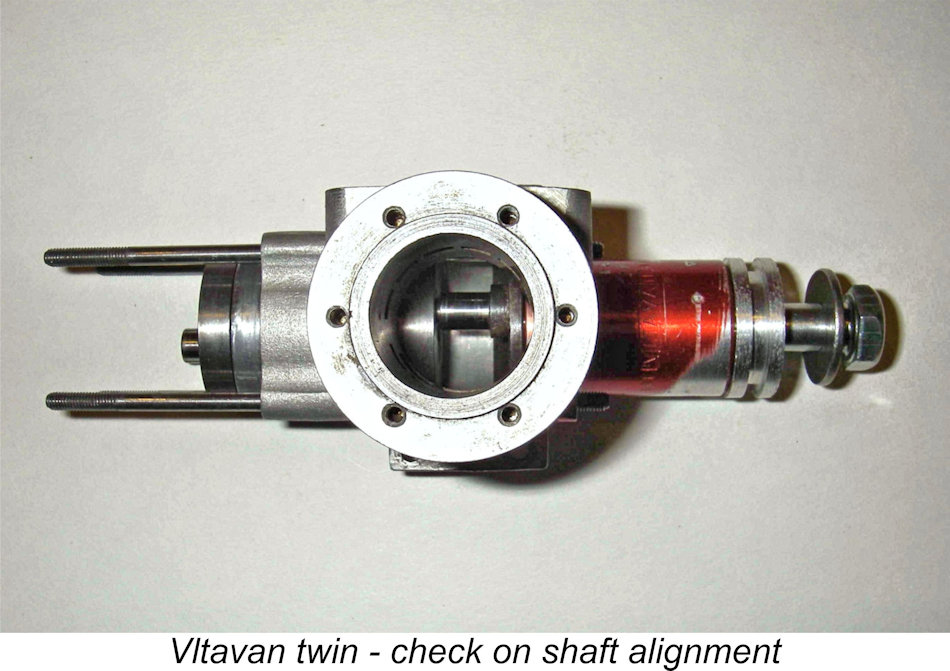
 between the two pistons, and the bores checked out as being essentially identical. This being the case, it didn’t seem to matter which piston went into which bore (although from here on in I would maintain the same relationships, naturally).
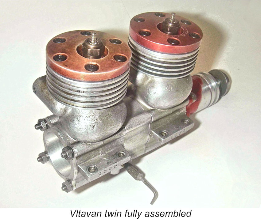 The carburettor was missing its spraybar, but everything else turned out to be there. I found a Super-Tigre spraybar which was a close clone of a standard Vltavan item and fitted the carburettor and needle perfectly without modification. Voila! One complete carburettor! All threads on the carburettor are metric, in keeping with the Continental origins of this motor.
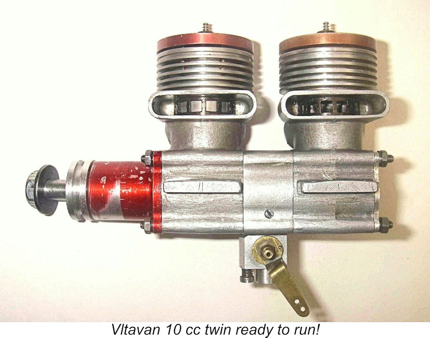
 As stated earlier, examples of the Vltavan twin were undoubtedly constructed by more than one individual. According to the very informative book entitled "
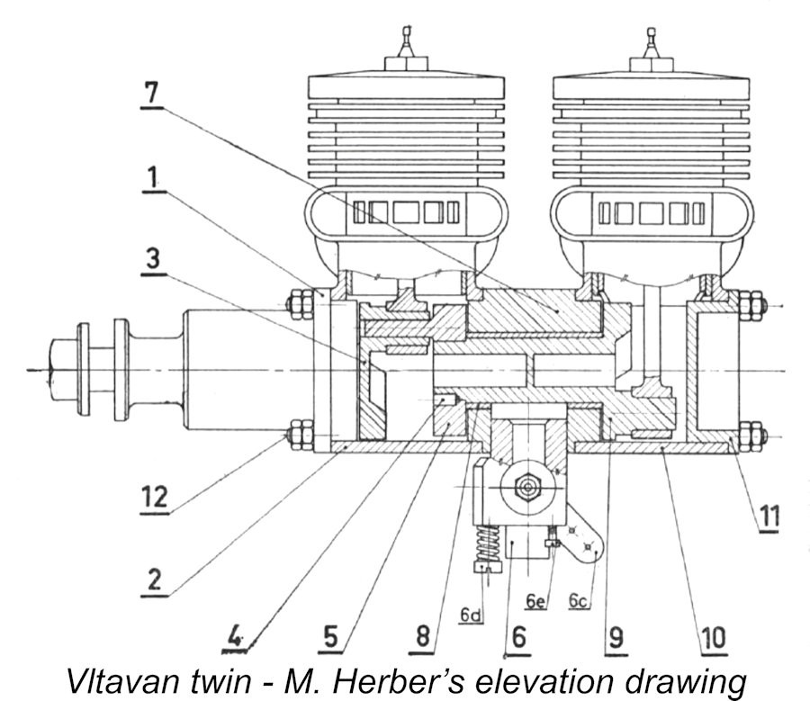
 I don't have dependable power absorption coefficients for the above props, but the speed achieved with the 10x4 Tornado nylon airscrew (a rather "slow" prop of that size) suggests an output at 12,000 RPM of around 0.490 BHP. The figure for the Tornado nylon 11x6 implies an output at 8,400 RPM of around 0.340 BHP.
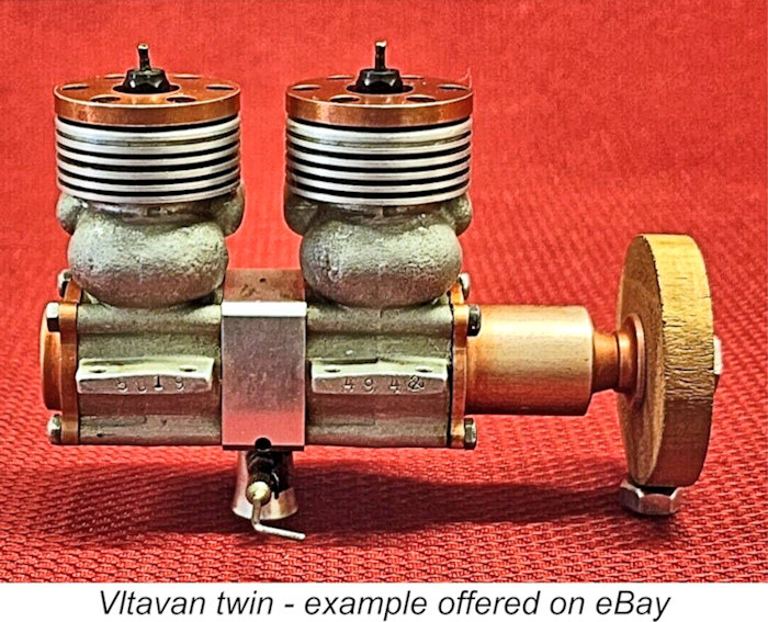
 Model Engines
| |