
|
|
The Mills 1.3 Marine Diesels By Maris Dislers
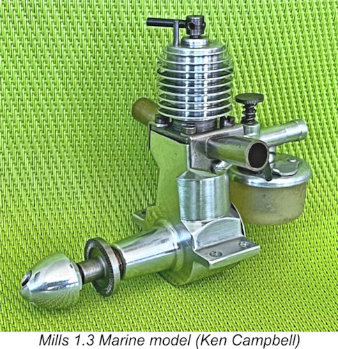
In 1948 Mills departed from their previous one-engine strategy. They diversified their range with new 0.75 cc and 2.4 cc offerings and an almost completely revised 1.3 cc model. With all of this going on, the new Mills 1.3 Marine engine which was advertised at the same time barely got a mention and is almost unknown now. I’m referring to the one with an aluminium crankcase, looking like a Mk. 2 magnesium-case Mills 1.3 but with screw holes under the exhaust area. Its very existence has confused some model engine collectors, as it doesn’t fit neatly into the broader narrative. In a separate article to be found on this website, Adrian and I have summarized the manner in which this model acquired its popular designation as the “Anniversary Model”. We’ve shown that this designation was undoubtedly the creation of an imaginative later collector rather than a name assigned by Mills Brothers. The truth is that this aluminium-case unit was actually the Mills 1.3 Marine unit released in June 1948. Mills Bros. themselves never referred to any “Anniversary Model”, nor did any reference to such a model ever appear in the contemporary modelling media. The name is a later invention. If any reader can prove us wrong, please submit your evidence!
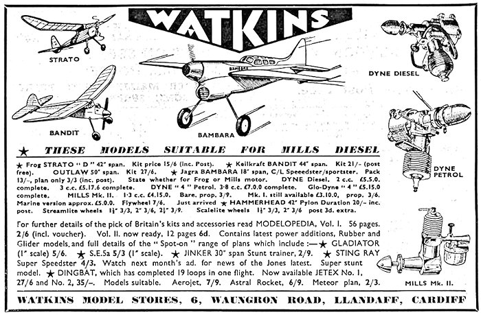
The engine only continued to appear in Watkins ads until January 1949, after which it quietly disappeared. Thereafter, the 1.3 Marine was mentioned as a one-liner in Mills advertisements in the January – May 1949 issues of “Aeromodeller”. The price was reduced to £5 5s 0d (£5.25) during this period. Little sales interest is implied ....... It seems that the marine engine was given its own serial number block - distinct (at that time) from the contemporary Mk. 2 aero engine. Known serial numbers ranging between 30002 and 30292 imply that this is by far the rarest of all of the Mills engines, with only 300 or so examples having been made. In his final installment of “The Mills Story” (Model Engine World, April 1996) Mike Noakes noted the Aeromodeller advert of December 1948, but did not associate the marine engine with the reputed “Anniversary Model”. His eagle eye spotted some later Mills adverts in November and December 1950 that included the 1.3 cc Marine unit “with fuel cut-out” selling for £4 2s 0d (£4.10). The engine appeared for the last time in the January 1951 issue. The complete absence of any contemporary listing of the marine engine or suitable boat kits in contemporary dealer adverts suggests that this represented a final token effort by Mills Bros. focused upon the Christmas 1950 season after a dismal previous sales performance. The Mills 1.3 Marine Model Described
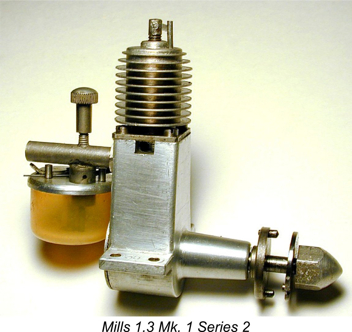
It seems very likely that a significant stock of unused Mk. 1 aluminium crankcases remained when the magnesium-case Mills 1.3 Mk. 2 Series 1 was introduced. The idea of creating the marine engine was presumably hatched as a way of using up these left-over aluminium cases. The extra weight of such a model was not important in marine service, while aluminium resists corrosion far better than the new magnesium alternative. This all fits in with the expanded range strategy as well as the Marine concept. To match the new Mills visual style, the aluminium crankcases were machined in the upper case “waistline”. There is evidence to suggest that the revised case machining was tried out initially by simply pulling a completed
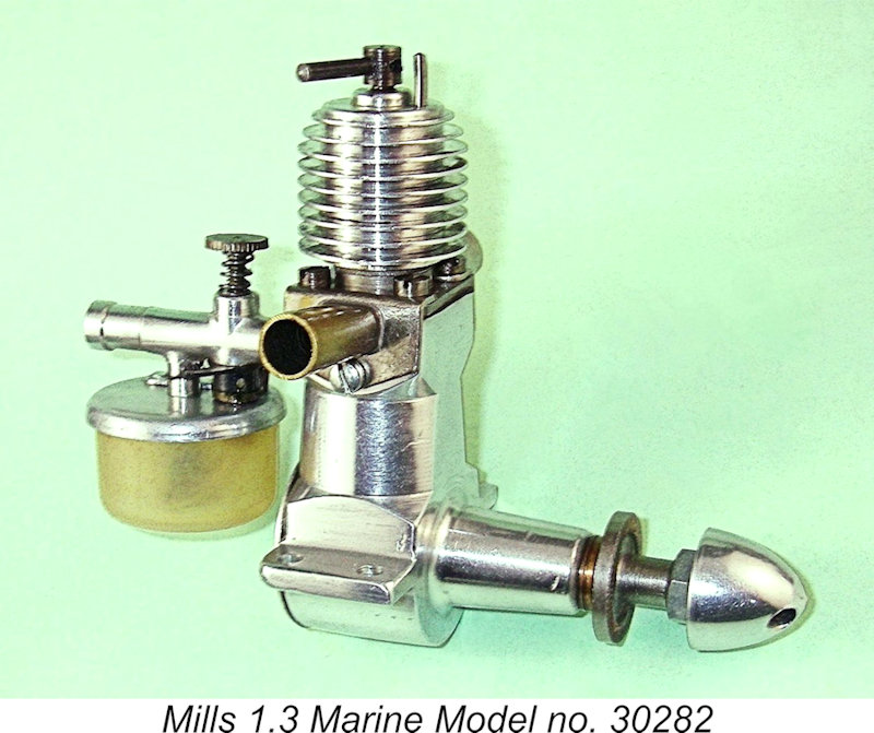
The exhaust stubs were formed from round brass tubing, flattened somewhat at the base and soldered to mounting flanges before being Watts nickel-plated against corrosion. The stubs were each retained by two of the cylinder hold-down screws and one additional screw below. To The advertising confirms that a flywheel was fitted in place of the aero components normally featured. It’s unclear whether or not the Mills 1.3 Marine was supplied with a tank – such a fitting would appear redundant in model boat service, where a separate tank would undoubtedly be used. The later Ripmax marine conversions certainly reflect this view (see below). With use in model aircraft being overwhelmingly more popular among Mills users, most surviving examples of these The stacks would actually have been something of an encumbrance in a typical aero installation, which explains their absence from many examples. However, a few do retain the exhaust stubs as seen at the right, but the flywheel shape remains a mystery. Jon Fletcher had an original Mills instruction leaflet which recommended a 4½ ounce flywheel having a diameter of 1¾ inches and a thickness of 7/16 inches for the Mills 1.3. Presumably the original 1.3 Marine models were equipped accordingly. No images of the original 1.3 Marine as supplied were published back in the day, nor are we aware of any currently-available images. Can any kind reader help with a photo of an authentic original Mills Marine example? The one remaining question is whether or not the original Mills 1.3 Marine model was supplied with a water-cooled jacket. It appears significant in that regard to note that the December 1948 Mills Bros. advert referred to the Marine model as being supplied “complete with exhaust stubs and flywheel” – no mention of a water-cooled jacket. If one had been included, surely it would have been mentioned? The fact that the air-cooling jacket was modified as described earlier implies that these modified jackets were standard equipment as supplied. The clincher seems to me to be the fact that the Henry J. Nicholls advertising categorized the engine as being “suitable for boats or cars”. Air cooling is clearly implied here. No surviving aluminium-case examples with water-cooled jackets are reported. Mills 1.3 development insights
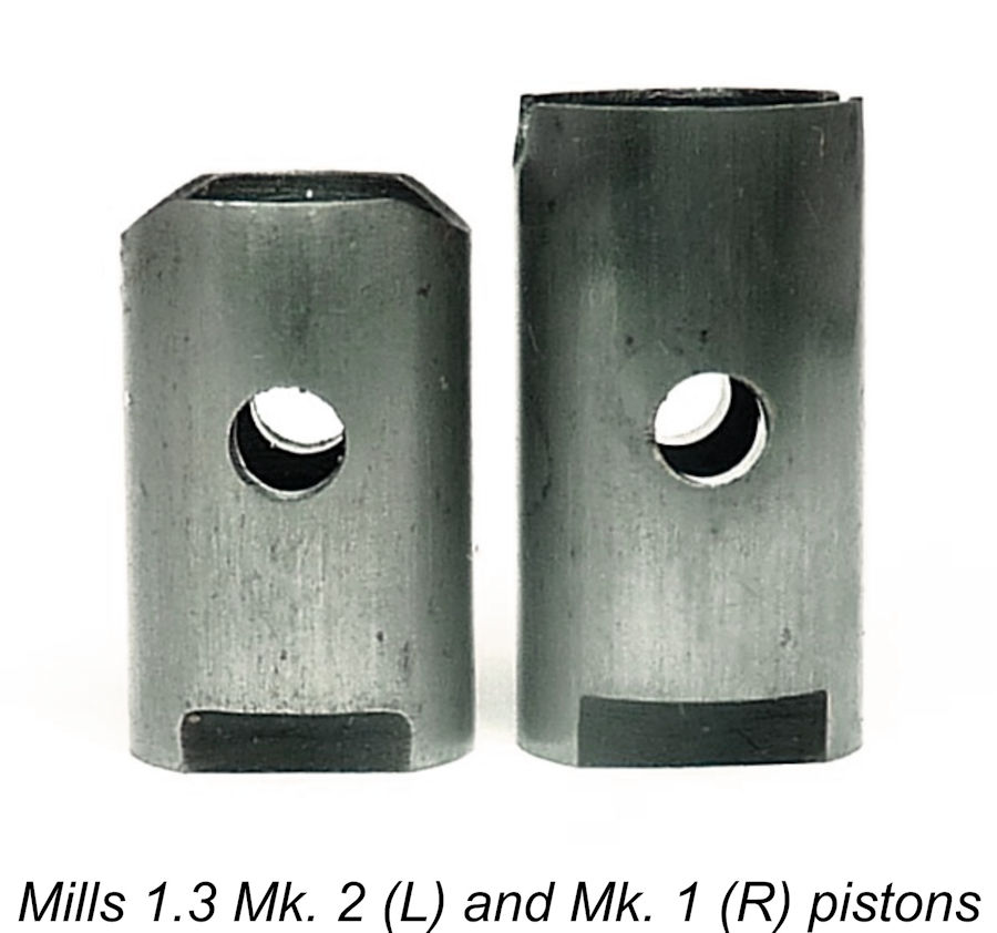
Pairing the old Mk. 1 cylinder with the new Mk. 2 piston, as in the Mills 1.3 Marine Model, increases the induction period from the original 76 degree specification to around 120 degrees. This was most probably a make-do pairing from existing parts to complete this batch of engines and move them out. While the effect on performance might not have been intentional (or even noticed by most model boat owners), it would have become quite evident during the factory check runs. That very likely led to a decision to upgrade the Mk. 2 Series 1 Mills 1.3 to Series 2 level with that new intake timing (by reverting to the Mk. 1 cylinder induction port location and lowering the carburettor aperture position in the crankcase to suit). It would appear that this revelation was kept under wraps until existing stocks of 1.3 Mk. 2 Series 1 cylinders and crankcases had been used up, or a product upgrade was deemed essential for commercial competitiveness. In the interim, as little as possible was made of the 1.3 Marine model to avoid letting the cat out of the bag prematurely. The Ripmax Marine Conversions
Descriptions of Ripmax Models
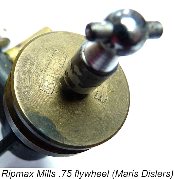
Jon Fletcher's previously-mentioned Mills instruction leaflet recommends a 4½ ounce flywheel having a diameter of 1¾ inches and a thickness of 7/16 inches for the Mills 1.3. The Ripmax flywheel is generally consistent with this recommendation.
Two exhaust tubes of 5/16 in. diameter brass tubing are soldered to flanges. Each flange is retained by small screws engaging threaded holes in the crankcase fore and aft of the exhaust apertures. The cast venturi is not machined for the tank retaining screw or shut-off, implying that Ripmax intended the engine to run with an external fuel tank – a logical assumptionin model boat service. This semi-finished component was clearly supplied by Mills Bros. in cooperation with Ripmax. The drilled and t Since the smaller Mills .75 used flats on the crankshaft to lock the prop driver, the Ripmax conversion retains its prop driver. The brass Jon Fletcher's previously-mentioned Mills instruction leaflet recommends a 2¼ ounce flywheel having a diameter of 1½ inches and a thickness of ¼ inch for the Mills .75. The Ripmax flywheel is considerably more substantial than this. The nickel-plated brass water jacket screws onto the crankcase, retaining the cylinder in the same manner as the standard aero head. It is stamped “E” on top. The crankcase is drilled and threaded in the exhaust areas to accept ¼ inch diameter screw-in brass tubing stubs. Presumably the cases were supplied to Ripmax in this configuration by Mills Bros. The venturi jet and intake components screw together in the usual manner. However, as the jet piece must be drilled through for air intake after assembly, it was clearly done thus at the outset, again indicating that there was no intention to fit a fuel tank to these engines. As stated previously, a completely logical concept when considering the engine’s intended use in marine service. Conclusion I hope that this article has done something to resolve a certain amount of confusion which has hitherto surrounded the Mills marine models which turn up from time to time. This is an interesting story which is well worth preserving! __________________________ Article © Maris Dislers, Glandore, South Australia First published August 2024 |
 From time to time, examples of the Mills diesels which are equipped for marine operation show up on eBay and elsewhere. In this article I’ll try to set the record straight on the subject of the Mills marine diesels.
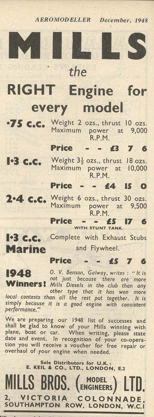
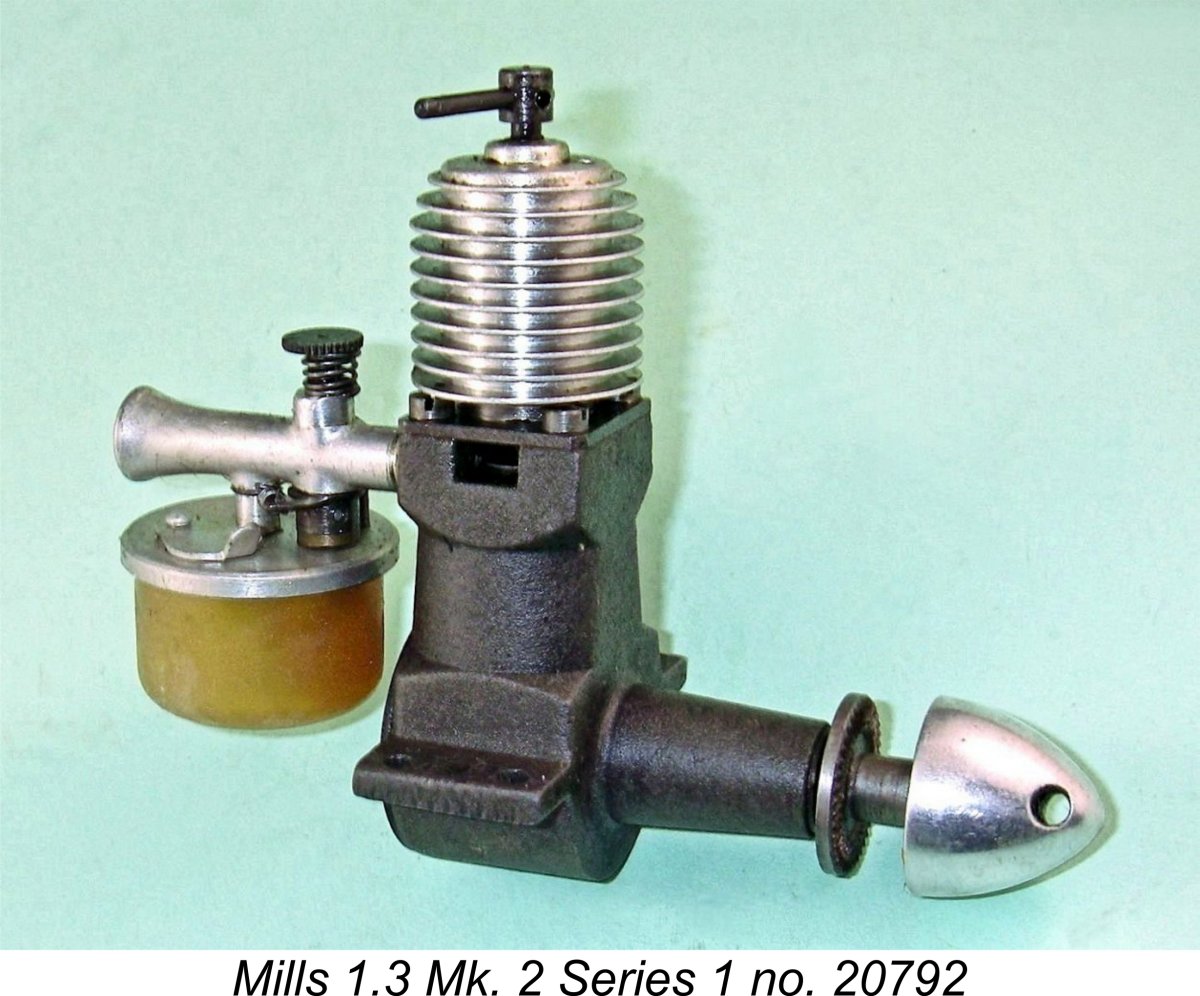 The comprehensively revised magnesium-case
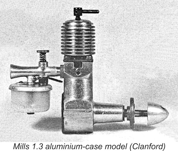
 The new model retained the Mk. 1 cylinder and conrod, again possibly utilizing left-over components. However, it featured the revised carburettor assembly, shortened piston and re-dimensioned crankshaft of the new Mk. 2 Series 1 model. Since the Mk. I crankcase is slightly shorter than that of the Mk. 2, a bronze spacer was fitted behind the prop driver.
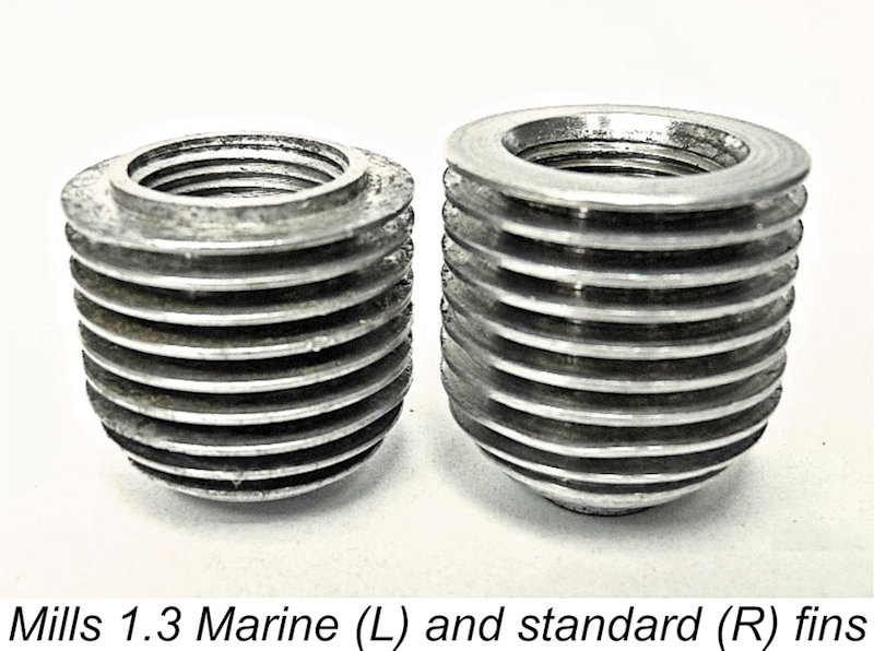
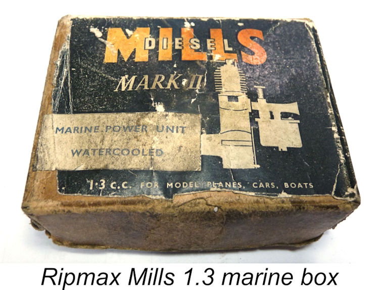 The Mills parts list does not include any marine components. Apart from the aluminium-case 1.3 cc Marine model just described, none of the other marine Mills engines encountered today are Mills Brothers originals, instead being conversions of original Mills aero models by Ripmax Marine Accessories Ltd., using their own marine components. As advertised in the mid-1950’s, Ripmax could supply suitable flywheels for Mills 0.75, 1.3 and 2.4 engines and water-cooled jackets for the 0.75 cc and 1.3 cc offerings. They also offered complete marine-converted 0.75 and 1.3 engines, priced at £4 1s 2d (£4.06) and £5 10s 10d (£5.54) respectively. These engines were sold in the regular Mills box, with a small sticker added stating that the box contained a marine unit.
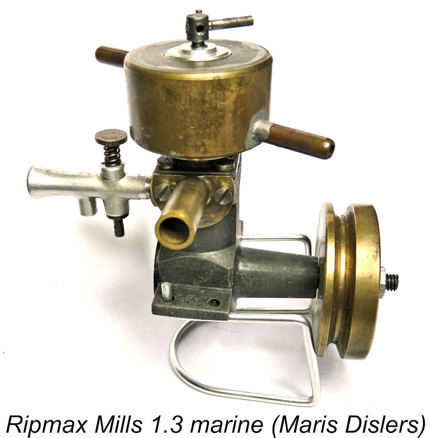 Unlike the earlier factory Mills Marine 1.3, the Ripmax conversion of the Mills 1.3 is based on the 1.3 Mk. 2 engine. Our example no. 32834 is a Series 2 type. The brass flywheel has a diameter of approx. 1
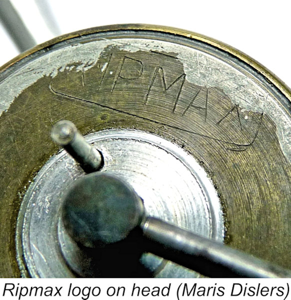 The brass water jacket is a close fit onto an apparently standard aero head, leaving the lowest cooling fin and top face exposed. It can be rotated to suit the desired positions of fill and drain pipes, but is not removable. It is possibly retained by an internal circlip. The water jacket is stamped with the “RIPMAX” logo on top, as seen at the right.
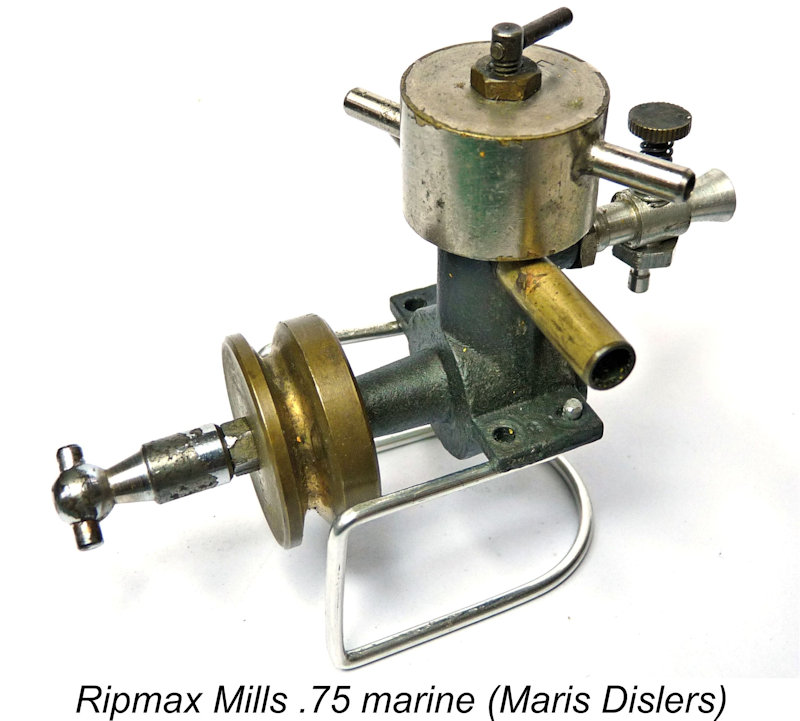
 flywheel measures approx. 1
| |