
|
|
The Original ETA – the ETA “5” Diesel By Adrian Duncan with Ron Chernich
A considerable amount of information regarding this iconic model diesel has long been available on the late Ron Chernich’s wonderful “Model Engine News” (MEN) website. This took the form of an article written by Ron himself which appeared on MEN in June 2006. Unfortunately, my mate Ron left us in early 2014 without sharing the access codes to his heavily-encrypted site. Consequently, the site has received no maintenance since Ron’s untimely departure and is now exhibiting unmistakable signs of the slow process of deterioration which must inevitably result. Check it out while it’s still there to be checked, guys!!
I wish to make it clear that all of Ron’s information is included in this article, which is as much his work as mine. I’ve simply clarified and re-organized the material somewhat, also adding some further information which has since come to light. I must also acknowledge my indebtedness to Lyndon Bedford for the provision of many background details which he alone could provide. In addition, Lyndon shared a number of images which greatly inform the background to the narrative. Having duly acknowledged my primary sources, I’ll begin by summarizing the chain of events leading up to the establishment of the ETA Instruments company and the introduction of the ETA “5”. Those already familiar with this story are cordially invited to skip this section of the article. Background Remarkably enough, it’s possible to trace the roots of the ETA model engine story all the way back to WW1! In 1916, the tides of war brought Charles J. Bedford to England from his native New Zealand. While in London he met an English lady who eventually became his wife. Following the conclusion of WW1, he and his new bride moved back to New Zealand with the intention of staying there permanently. The couple started their family there, producing two sons, Eric (b. 1920) and Ken (b. 1924), both of whom were born in New Zealand. Charles Bedford opened a garage with an engineering shop in the rear in Turua on New Zealand's North Island.
Upon arrival in England, the mechanically-minded Charles Bedford resumed the business that he knew so well, opening a motor garage on Hempstead Road in Watford, a town located in Hertfordshire a little to the north-west of London. The business was identified as the Hempstead Road Motor Company. Charles bought a house in Ilford, very distant from his place of business. This was a rather strange location for his residence, since it required him to make a Incidentally, as of 2012 after the passage of some 85 years, this garage still existed, although it had changed hands many times by then. The area has subsequently been re-developed, with the former garage site being occupied today by the Watford Leisure Centre. Here Charles conducted business as a motor vehicle sales agent as well as providing automotive repair and maintenance services for all makes. From their early teens, Ken Bedford and his older brother Eric began to take an active part in the operation of the business as time permitted, gaining valuable experience thereby. The business soon expanded into the field of general precision engineering in addition to the automotive side. The company traded at this time under the name Bedford Products and Light Engineering Co. Ltd.
In addition to this, Ken had developed his artistic talents both as a photographer and a musician. He had become a highly proficient saxophone player, performing periodically with various big bands including the famous Ted Heath dance band, which was characterized by no less an authority than Count Basie as being on par with the best American big bands. It was during the war years that Ken first met his future wife Dorothy at a fireworks party in Harrow. A friend of Dorothy’s asked around to see if anyone could go and fetch her to the party. Ken was the only one there with a car, so he obliged. He and Dorothy hit it off immediately and were together constantly from that time onwards. They married in 1945 and their first son was born in 1947, with my valued informant Lyndon following in 1950. The marriage was to last for the next 66 years until Dorothy’s death in 2011 following a stroke.
The logo of the new company featured the Greek character η for the letter “eta” that is used in science and engineering to stand for efficiency - a particularly apt choice for a firm which was to become so well-known as a manufacturer of high-quality competition engines. The makers themselves referred to this logo as the "symbol of efficiency"! The “instruments” part of the name arises from the fact that the firm made a variety of precision instruments and tools, including a range of small scales for various applications. Model engine manufacture was just one of a number of successful business lines. When the new ETA Instruments venture was started, it would appear that the Bedford family had a considerable stock of blank drafting sheets which bore the former company name of Bedford Products and Light Engineering Co. Ltd. It's certainly true that drafting sheets bearing this name continued to be used for the company's design drawings well into the 1950's - very thrifty!! As 1946 drew on, the burgeoning popularity of power modelling in Britain at this time coupled with a strong family interest in the hobby led the Bedfords to decide to expand their production activities into the field of model aero engine manufacture. A “Miniature Engine Division” of the ETA company was quickly established, with its activities evidently being located initially "in the back room" at the Watford Bypass location, since the business address at this time was specifically given in the advertisements as being on the Watford Bypass. The first product of the new model engine venture was none other than our main subject, the ETA “5” sideport diesel of 4.99 cc displacement which appeared in late 1946 and was to remain in production or at least on offer through several variants until early 1950. It appears that most if not all examples of the ETA "5" were manufactured at the Watford Bypass location.
The former facility on the Watford Bypass has since survived to become the main regional sorting facility for the Post Office, although it has been extensively re-modelled in association with this change of use. The replacement facility on High Street has also survived, serving in later years as a furniture warehouse. Production History
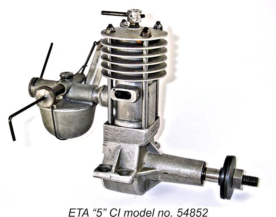
From the outset, all examples of the ETA “5” bore serial numbers neatly stamped onto the front of the upper crankcase below the bypass. Since these numbers are highly informative, it’s worth explaining the system here. The engines carried five- to seven-digit serial numbers seemingly denoting the month of production. the year of production and the number of the particular engine in the production sequence for that month. Thus, illustrated engine no. 54852 was produced in May 1948 and was the 52nd example produced that month.
The ETA ad from the April 1948 issue of “Aeromodeller” reproduced at the left stated that a new version of the ETA “5” to be called the ETA Super “5” D was scheduled to appear in June 1948. However, that model failed to appear The ETA Super “5” model which had been mentioned back in April was still said to be “pending” as of June 1948. A surviving prototype acquired by my good friend Miles Patience from the estate of Eric Bedford shows that this was to have been a twin ball-race disc rear rotary valve (RRV) version of the ETA “5”. However, this variant of the engine A certain amount of confusion arises from a close reading of the heading in the October 1948 “Aeromodeller” advertisement (below right), which refers to the two advertised ETA “5” models as belonging to the 1948 Whatever the facts of that matter, evolving market conditions had evidently convinced Ken Bedford by this time that the days of both large long-stroke diesels and petrol (spark ignition) engines were done and that a more promising future lay in the development and marketing of high-performance glow-plug engines. In taking this view, Ken was reportedly somewhat at odds with his older brother Eric, who apparently remained far more interested in pursuing the further development of diesel engines such as the projected Super “5” model. However, it seems that Bedford Senior cast the tie-breaking vote in favour of the switch to glow-plug ignition which was to sustain the company’s miniature engine division for the next dozen years.
Having summarized the history of the ETA “5” in broad terms, it’s now time to zoom in and take a closer look at the engine itself. This section of the article is drawn to a large extent from Ron Chernich’s original review of the engine from June 2006. The ETA “5” – Description
The crankcase, cylinder head, and tank top are aluminium die castings with either a shiny or fine matte grey finish. The shiny finish seems to have been applied only to the earlier examples of the engine. The company designated the matte grey finish applied to most of their engines as the “Etamatt” finish, specifying this finish by that name on many of their shop drawings. Some reviewers of the engine have taken this fine matte finish to have been produced by anodizing, which produces a very hard non-conducting aluminium oxide layer (aluminium oxide granules are commonly used as an abrasive). However, a test of a matte-finished case using an ohm-meter showed the surface to be fully conducting, strongly suggesting that the cases were not anodized. Ron Chernich considered it to be more likely that the surfaces were finished by sand-blasting or (less likely) by post-casting heat treatment.
The engine features a number of unusual and innovative features. The cast-iron piston is shrunk onto an internal alloy gudgeon pin carrier. The result is a piston unmarred by holes and no possibility of the pin rubbing on the cylinder walls, jamming in the transfer or inlet ports, or ever being removed! Four long studs screw into the crankcase, following a pattern established previously by early FROG model engine designer George Court. Domed hex nuts engaging with the tops of these studs pull the head and cylinder down onto the crankcase seat. As supplied, one of these head nuts was extended so that it restricted the available range of compression adjustment to one turn. In addition, the tommy-bar was screwed into one of two tapped holes at 90° to each other in the compression screw to allow a running location of the tommy bar to be established and set at the factory. The intent of these measures was to prevent owners from over-compressing the engine, or "losing" the setting by backing off too far. This scheme was common on early diesels - probably influenced by its appearance on the Dyno.
The crankcase has its lugs set for center-line mounting, reinforced by webs in a rather Westbury-influenced way. The short exhaust stubs are drilled and tapped fore and aft to allow the optional aluminium exhaust extension tubes to be fitted and retained with small machine screws. These fittings are seen in the accompanying image. The turned screw-in backplate has a complex rebated internal flange with four semi-circular holes to provide purchase for a pin spanner. A similar design was later adopted on the early Elfin engines.
Eagle-eyed readers will have noticed the spinner nut which appears in the ETA advertisement photo, the “Aeromodeller” cut-away drawing and one of Bert Streigler's engines, while the other examples and the “Aeromodeller” 3-view drawing show a plain hex prop-nut. Ron Chernich was able to confirm that both are correct, as the engines were supplied with both fasteners! The spinner nut was counterbored to cover the nut, providing some additional safeguard against things coming undone. The ETA “5” instruction leaflet stated quite clearly that the spinner nut’s role was purely to protect the prop installation thread – it was not to be relied upon as a prop fastener. This scheme has also appeared on certain Taipan engines.
The ”R” version of the ETA “5” was basically identical to the standard CI version described above apart from having a standard screw-in intake venturi with no provision for a tank or any of its attendant complexities. It also featured a cylinder head and spinner nut which were anodized red. It was apparently developed primarily for model car applications, a field in which Ken Bedford in particular had a keen interest, but was also promoted for control-line stunt use. The omission of the complicated tank assembly allowed it to be sold for £1 less than the standard model. Even so, neither model was cheap by the standards of the day – as of October 1948, the CI variant sold for £7 19s 6d (£7.98) while the “R” version was offered at a still-hefty £6 19s 6d (£6.98). This was at a time when the average weekly adult wage in Britain was around £5 10s (£5.50), making the engine very much an upmarket “luxury” item. This would obviously have affected sales figures – indications from reported serial numbers are that no more than 1500 or so examples ended up being manufactured in total. The ETA “5” on Test
Sparey reported that hand starting was used throughout, with “no difficulty” being encountered with the engine either cold or hot. By this, we may assume that Sparey found the ETA “5” to be an easy starter – he made no mention of any problems with prop slippage during starting. Sparey also stated that the cut-out was “efficient at all reasonable speeds” but become somewhat unreliable at the highest speeds tested. The latter finding was characteristic of Sparey, who often reported problems with cut-outs which work perfectly well for others. On the negative side, Sparey found the engine to be relatively inflexible in terms of its performance, stating that the speed range within which the engine would run smoothly and evenly was “somewhat limited”. He managed to measure a peak output of just over 0.18 BHP @ 6,250 RPM, which he viewed as a good result for an engine of this displacement at the time. This result compared quite well with the manufacturer’s claim of 0.20 BHP at an unspecified speed below 7,000 RPM.
Writing years later in 1994, Gordon Counsell conjectured that the unusually sharply-peaked power curve shown in Sparey's review of the engine - and other reviews that he conducted - was a result of improper testing technique. Counsell suggested that Sparey may have varied the engine speed by adjusting the engine settings rather than by changing the load and operating at the optimum setting for that load. Given the uncharacteristically sharp peak of the curve provided with the ”Aeromodeller” review, this is not an unreasonable conclusion, although I’d hate to believe that Sparey would have been unaware that such an approach would invalidate his performance figures. But narrow-range port timing could also account for this and could explain why the engine only seems happy operating within a narrow RPM band.
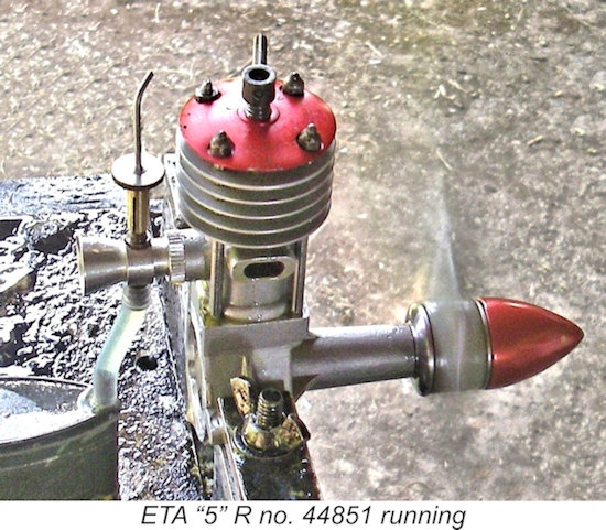
Sparey’s test report listed the prices of accessories available for the engine. The exhaust extension tubes and extended filler tubes mentioned as optional accessories at the end of the review are visible on the example in the accompanying photograph. The report makes no mention of the "R" model, and the price quoted matches that for the "CI" in the ETA advertising. However, in the list of accessories we see: "Fully machined Flywheels, 12s 6d each. Short venturi intakes for control line or special applications, 14s 8d complete." This implies that the “R” model had indeed appeared by this time, as surmised earlier. Certainly, its induction components were on offer.
Gordon noted a few operational characteristics which had not been mentioned by Sparey. He found that the usual approach to slowing the engine down by reducing compression invariably resulted in a dead stop! The same behavior resulted from the use of the rotary choke for the same purpose. Ron Chernich reported that this "one-speed only" characteristic had been confirmed by Ken Croft when running the example in his collection. However, Gordon’s main beef was the insecurity of the prop mounting system, which did not incorporate a taper to help secure the prop driver. This system apparently allowed the prop to slip on the shaft with the least provocation. Gordon got around this by borrowing a MERCO 49 prop driver and tapered collet to fit to his engine while in service. Actually, if you have access to a lathe, it's a simple matter to cut an internal taper into the prop driver and make a matching-tapered brass split collet to suit. My own example of the ETA "5" R variant, engine no. 44851, has been modified in this way. The ETA “5” was the subject of a third test, this time by Dick Roberts, which appeared in Volume 5, Number 7 of MEW dated November 1998. Like Gordon Counsell before him, Dick spent much of his report describing the engine’s construction in great detail. He rightly characterized the ETA “5” as being “extremely well made”, although he admitted that it was “big and heavy for its capacity” by latter-day standards. In terms of the engine’s performance, Dick began by trying it with a 12x6 Graupner Super airscrew. After some adjustments to the settings, he quickly achieved a start and was able to set the controls to give a smooth and steady speed of 6,100 RPM, which turned out to be right around the engine’s peaking speed. Once the settings were established, a warm engine required only two choked turns and a few flicks to get it going. The tank was found to have more than sufficient capacity, providing a running time of around 2½ minutes on this prop. The cut-out too worked very well at all speeds tested, also providing a useful check on the needle valve setting. It will be recalled that this cut-out worked by closing off the fuel supply. Consequently, if the engine speeded up a little before cutting out, this was a positive indication that the needle was set too rich. Somewhat to Dick’s surprise, the ETA’s taper-less prop driver mounting gave very little trouble, only slipping when the engine was flooded to the point of significantly increasing the flicking load on the driver. It was necessary to tighten the prop-nut more forcefully than normal, but if this was done the system appeared to function as designed. Dick’s only caution here was that the required tightness might cause compression of a wooden prop hub, making it advisable to check tightness periodically when using wooden props. Dick reported the following prop/RPM data on test:
The above data appear to imply a peak output of around 0.190 BHP @ 6,000 RPM. These figures are actually quite consistent with the performance reported much earlier by Sparey, also being well in line with the manufacturer’s performance claims. However, even the manufacturer’s performance claims fell well short of the figures being achieved by other contemporary 5 cc diesels such as the British “K” Vulture and the Drone Diesel from America. It’s little wonder that ETA Instruments elected to abandon the ETA “5” in favour of new models having far greater performance potential. A Latter-Day Re-Appraisal
I was mindful of the fact that both examples have had little if any previous use, accordingly requiring a full break-in to realize their full performance potential. Since I wasn’t planning to use them in a flying context, I could see little point in completing a full break-in. This being the case, I elected to begin by trying them rich and under-compressed using the same APC 12x6 airscrew which Dick Roberts had found to allow his test CI example to run at or very near its peak – somewhere around 6,000 RPM. My approach was to run the engines at slightly rich and under-compressed settings on this prop, leaning out very briefly at the end of the run both to measure the speed and to subject the piston/cylinder assembly to the full-range heat cycles which are so essential to a good break-in of an iron-and-steel piston/cylinder set. The results might be amenable to improvement with a full break-in, but the data would at least provide a good approximation of the engines’ performances. More importantly, the engines’ fine LN condition would be maintained. The presence of the prominent stiffening lugs at the centre of the mounting lugs precludes the use of a standard test stand to mount this engine. Fortunately, having experienced this issue before with other engines, I’ve cut angled slots into the mounting faces of my test stand’s upper clamp jaws, thus accommodating such stiffening webs without causing damage to the webs. Others, please copy – no marred or filed stiffening webs, please! Conservation is important ………..
Frankly, I was expecting a little trouble with this one due to the taper-less prop driver mounting. Accordingly, I tightened the prop-nut considerably more forcefully than usual. I may as well say right now that in the event I experienced no real problems with prop slippage during starting – it only happened once during the entire test. Provided that the prop-nut is really well tightened down, the system seems to work quite adequately. However, I must say that I would have preferred a conventional tapered prop driver mounting. Choking this engine is a bit “different”! You can’t finger-choke it because of the dual opposing air intakes, which are inconveniently located to allow "pinching". Instead, you simply close the rotary air control at the rear of the intake tube and flick once or twice. Then open the air control once more, and you’re set! I found that applying a couple of choked flicks in this manner followed by a small exhaust prime produced more or less instant results – the engine fired immediately and started with a couple more flicks. This extremely easy starting was maintained throughout the test. I’d guesstimated the initial starting settings pretty well spot on, allowing the engine to keep running once it started. Response to both controls appeared to be very progressive, making the establishment of a slightly rich under-compressed setting quite straightforward. Here I should add that I experienced none of the problems reported by Gordon Counsell – compression reduction had the usual effect of merely slowing the engine down and initiating a mis-fire. At no time did the engine stop following a modest compression reduction.
At the end of the fifth run, I found that the ETA was turning the 12x6 airscrew at a dead smooth 5,700 RPM when leaned out, a little slower than the figure reported by Dick Roberts. Of course, my engine was still more or less new in terms of running time, and I’d expect this figure to climb somewhat following a bit more breaking in. Regardless, I then tried the engine on the same set of props that I’d used previously for testing a couple of examples of the contemporary D-C Wildcat 5.3 cc sideport diesel. I used the same procedure each time – allow complete cooling from the previous run, fill the tank, open the needle a little, start the engine, let it run rich and under-compressed for 2 minutes and then lean out and adjust compression for the best speed. Running when leaned out was completely smooth and miss-free. There was certainly some vibration, but no more than I had been expecting given the engine's design features. If the engine was still running after the reading was taken, I saved fuel by using the cut-out to stop it, finding that the device worked perfectly at all times. Then change props and repeat the sequence. In this way, the break-in continued even while I was obtaining my data. The results obtained were as follows:
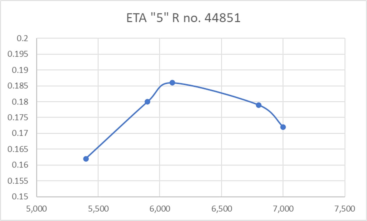
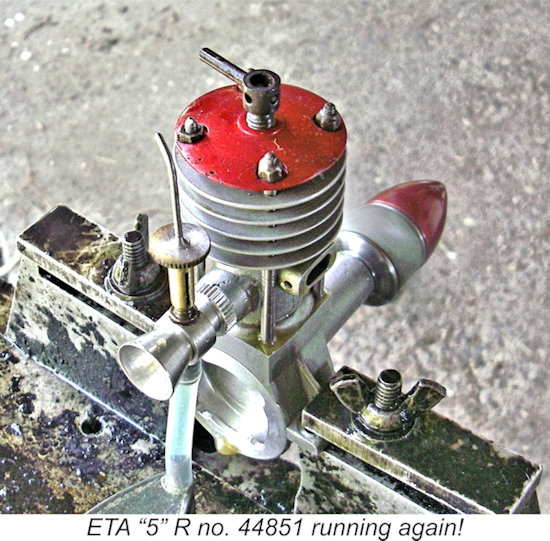
As can be seen, the additional running brought the speed on the 12x6 prop up to 5,800 RPM. I’d expect a further modest improvement with more running time. Although I evidently didn’t have a prop which allowed the engine to run at its peak on the bench, the general trend implied by these figures seems clear enough – the engine appeared to be developing a peak output of around 0.175 BHP @ 6,400 RPM. Pretty good confirmation of Sparey’s figures, although falling somewhat short of the manufacturer’s claim. Having completed the series of prop/speed measurements, I proceeded to try the effect of adjusting the rotary air control during operation. I was a bit surprised to find that the control actually worked quite well as a form of speed control. It’s true that response to this control was a bit on the sensitive side – it was quite easy to go just a little bit too far and choke the engine to a stop. After such a stop, it was flooded and became a bit of a challenge to re-start! For best results it was necessary to adjust both the air control and the needle valve together. Not worth the hassle ............. The most serious problem was that the control tended to “wander” from its setting due to vibration, making its use as a crude throttle for testing and trimming purposes rather undependable. I found that more reliable results could be Having brought my test of the ETA “5” CI model to a successful conclusion, I removed it from the test stand and mounted its ETA “5” R relative in its place. This unit is far more familiar in terms of its general layout – no tank, and no intake control complexities. I had to arrange a separate fuel tank for this engine. The R model proved to be every bit as easy to start as its CI predecessor in the test stand, responding immediately to a couple of choked flicks and a small exhaust prime. Once running, it was just as easy to set. Since Dean Clarke had used a conventional split collar to mount the prop driver when restoring this particular example, there was no possibility of any unwanted prop slippage occurring. I followed exactly the same procedure with this engine that I had employed previously with its CI relative, putting a few break-in runs on it and then continuing the break-in while taking my readings. The engine performed flawlessly throughout. The following data were eventually recorded:
As can be seen, this engine appeared to develop slightly higher levels of torque than its CI companion. Perhaps the somewhat less encumbered intake has something to do with this. An overall comment which may be made with respect to both engines is the indication from both of the above tests that the useable speed range of both models seems to be rather limited, just as noted by other testers. It appears that the rather sharp-pointed power curves developed by others are actually quite reflective of reality. In both cases, the useful speeds appear to be confined to the 5,000 – 7,000 RPM range – operation outside this range involves an unacceptable sacrifice of the engines’ performance potential. Even so, I was quite impressed with both of these units. Their quality shines through in all aspects of their construction, while their handling and running characteristics leave little to be desired. The most obvious strike against them is their somewhat marginal power output, especially considering their bulk and weight. That said, they do swing a pretty serious airscrew with sufficient authority to fly a sizeable model provided that speed is not an over-riding issue – these engines are sloggers rather than powerhouses! Either a 12x6 or a 12x7 would suite them nicely. Conclusion In his well-known 1977 model aero engine book, the late O.F.W. Fisher characterized the ETA “5” as "...the first quality English 5 cc diesel." In terms of the engine’s overall quality, he was undoubtedly correct. That said, there seems to be little doubt that the ETA "5" lacks the flexibility and wide speed range normally associated with long-stroke compression ignition engines. It is also undeniably somewhat down on power compared with other contemporary 5 cc diesels. But to offset those negative characteristics, the unmistakable ETA “5” has character in buckets! Today, the engine is an icon among large early British diesels. And, like the contemporary 5.32 cc D-C Wildcat, it had a relatively short production life, making it relatively rare and highly attractive to present-day collectors. Well worth a flutter if you encounter one in good condition! For those interested, the further activities of ETA Instruments Ltd. have been fully documented elsewhere on this website. ________________________________ Article © Adrian C. Duncan, Coquitlam, British Columbia, Canada First article by Ron Chernich published on MEN June 2006 This revised article published here |
||
 Here we’ll share a look at a pioneering-era model diesel engine of some historical significance, namely the ETA “5” diesel of 1946 – 1950. This engine is notable for being the very first model engine to be produced by the famous ETA Instruments company of Watford, Hertfordshire, England. Indeed, it was one of the earliest British commercial diesels of them all.
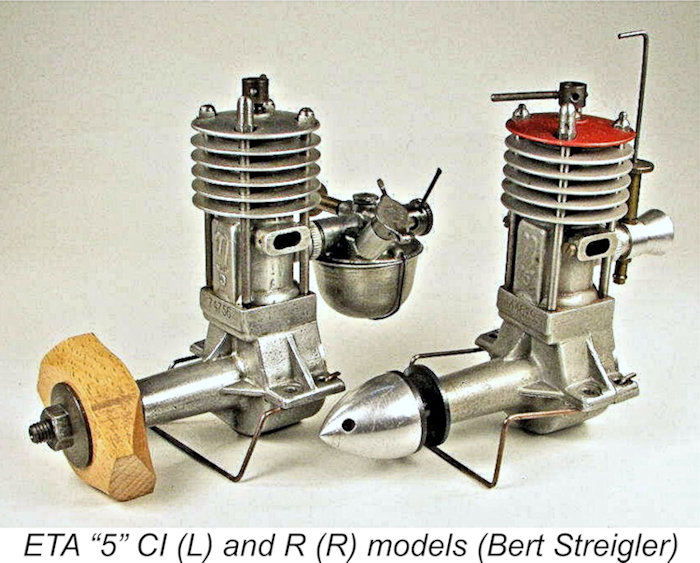 I was unwilling to accept the risk of the potential loss of Ron’s efforts to document the ETA “5” through the decay of MEN, hence the appearance of the present article on my own site. In addition, some further information on the engine has since become available, including the conduct of latter-day tests of both variants of the ETA “5”.
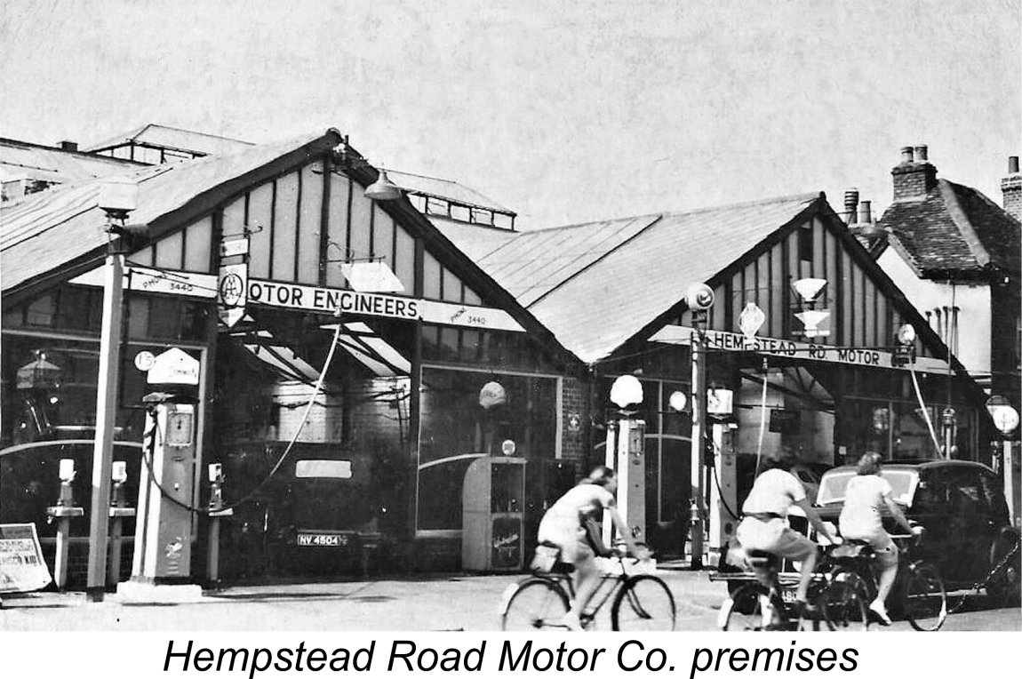 If the family had remained in New Zealand as originally intended, we would probably never have heard of the ETA model engine range! However, circumstances soon arose which resulted in a return to England. Firstly, the new Mrs. Bedford had difficulty adapting to life in New Zealand. This wasn't a positive factor, but the real crunch came in 1926 when Charles Bedford's premises in Turua were completely destroyed by fire. Combined with Mrs. Bedford's wishes, this event quickly led to a decision by the couple to relocate back to England, taking their two young sons with them.
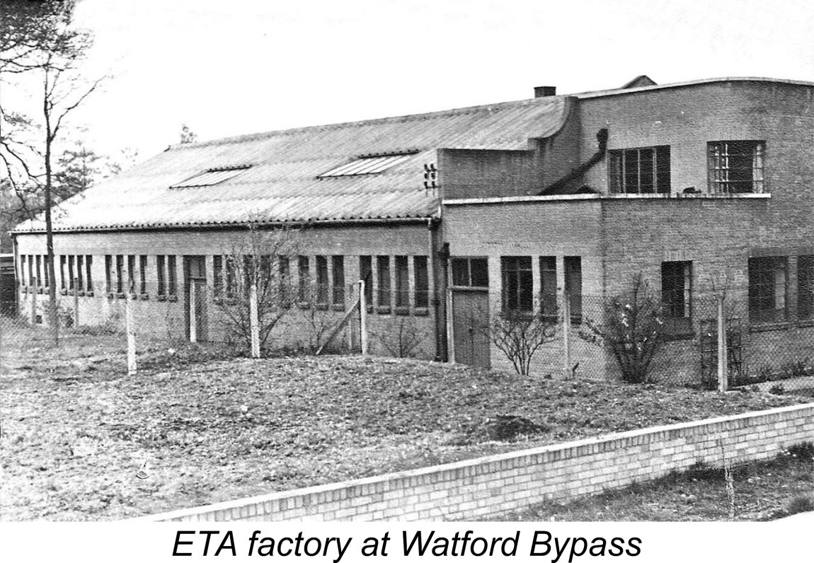 During the latter part of the 1930’s the business grew and prospered, prompting a move of the precision engineering operations into far larger factory premises on Colonial Way off the Watford Bypass. When WW2 broke out, the family’s engineering operation at this location was at the height of its success. The members of the Bedford family were soon working flat out making precision parts for the war effort. Speaking years later to Malcolm Ross, Ken Bedford recalled that at one point there were over 250 employees and rows of machine tools making precision components as accurately and carefully as possible, while German raiders were dropping bombs everywhere. Luckily the premises suffered only light war-related damage throughout that period.
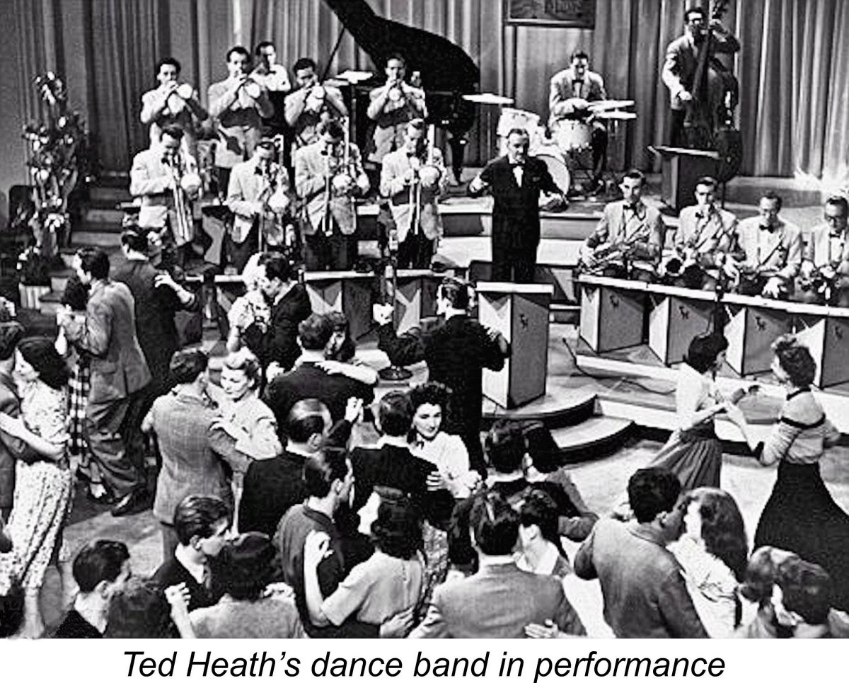 Naturally, their involvement in the high-pressure work programs dictated by the needs of the war effort provided young Eric and Ken Bedford with invaluable hands-on experience in the precision engineering field. By the end of the war, both brothers had become accomplished young precision engineers. They had also become partners in their father's business.
 After the war, most of the precision engineering work dried up more or less overnight, causing the business to contract severely. Nonetheless, the partners wished to continue their former activities in the field of light precision engineering. They established a new downsized precision engineering venture trading under the company name of ETA Instruments Ltd.
 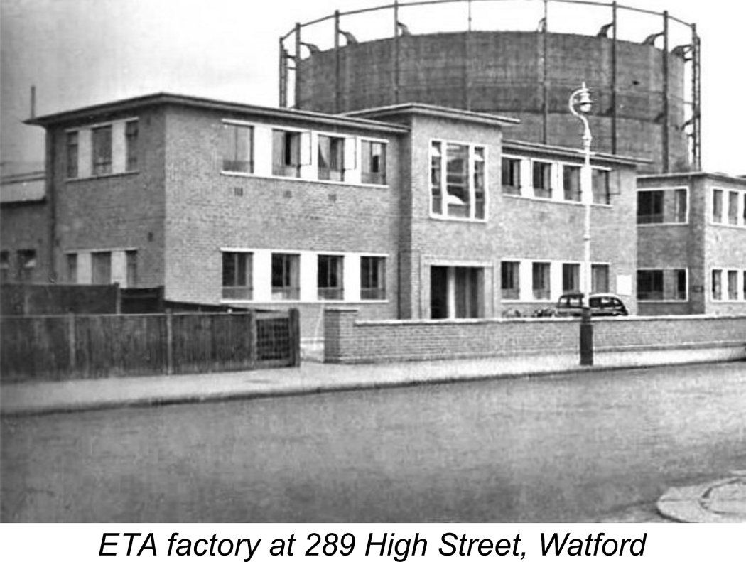 It soon became clear that the Watford Bypass premises were far larger than now required for the downsized company. A new manufacturing facility was therefore established at 289 High Street in Watford. Lyndon Bedford advised that the High Street facility was completed during 1949. However, for reasons which are now obscure, the company's advertisements from early 1950 until early 1952 cited their address as being 5 Hempstead Road in Watford, characterizing it as their "new address". This address appears to have been associated with the family garage operation, which was evidently still owned by the partnership. It appears that the manufacturing and business activities were being kept separate at this time.
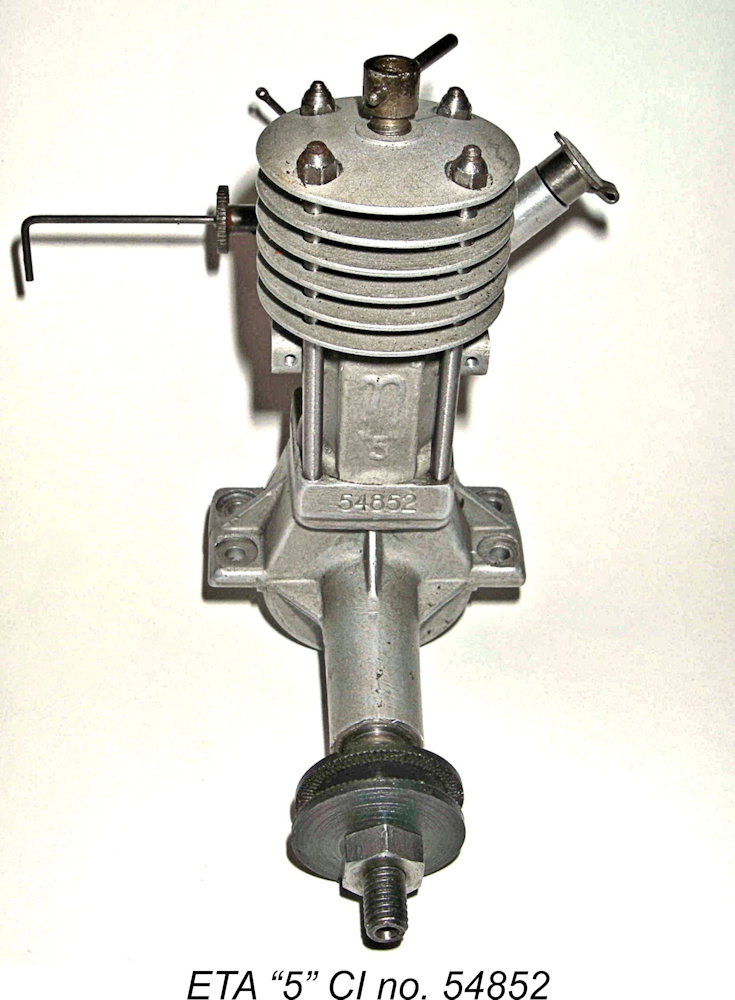 The ETA “5” was designed primarily by Eric Bedford. At this stage, the role of Charles and Ken Bedford was largely confined to the creation of dies and tooling for production of the engine as well as participation in the actual production process. An unusual aspect of the ETA model engine venture was the fact that from the outset everything was made in-house. This included the high-quality castings for which the ETA engines were always noted.
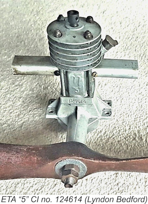 The production history of the ETA "5" is most easily traced through a perusal of the series of factory advertisements through which the engine was promoted. It has long been put about that the ETA "5" first appeared in mid-1947, since it was first advertised nationally in July 1947. However, Ken Bedford’s son Lyndon Bedford has produced irrefutable evidence in the shape of illustrated engine no. 124614 that the ETA "5" was in existence as of late 1946 - that serial number identifies this example as the 14
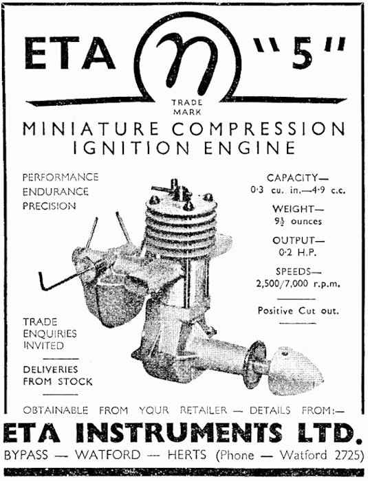 The ETA “5” made its national advertising debut in the July 1947 issue of "Aeromodeller", as reproduced at the right. It appears that the company was still developing its connections with the national retail model trade at this time, since trade inquiries were specifically invited. Deliveries of the engine were said to be "from stock", meaning that the company had an inventory of these engines on hand at the time of this advertisement. Presumably this was a consequence of a slowdown in direct sales as local demand became increasingly satisfied, resulting in an inventory build-up which would require the involvement of the nationwide retail trade to disperse.
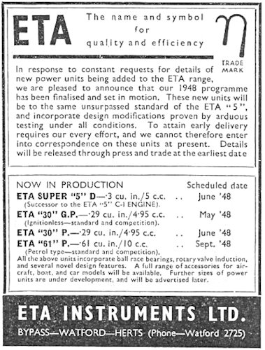 From the outset, the ETA "5" was noted for its fine workmanship and for the excellence of its castings at a time when many British "garden shed" products lacked such positive attributes. Following its mid-1947 national advertising debut, the engine enjoyed a period of considerable popularity. However, by 1948 its design was beginning to lag somewhat behind that of some of the new models which were beginning to appear from other manufacturers.
 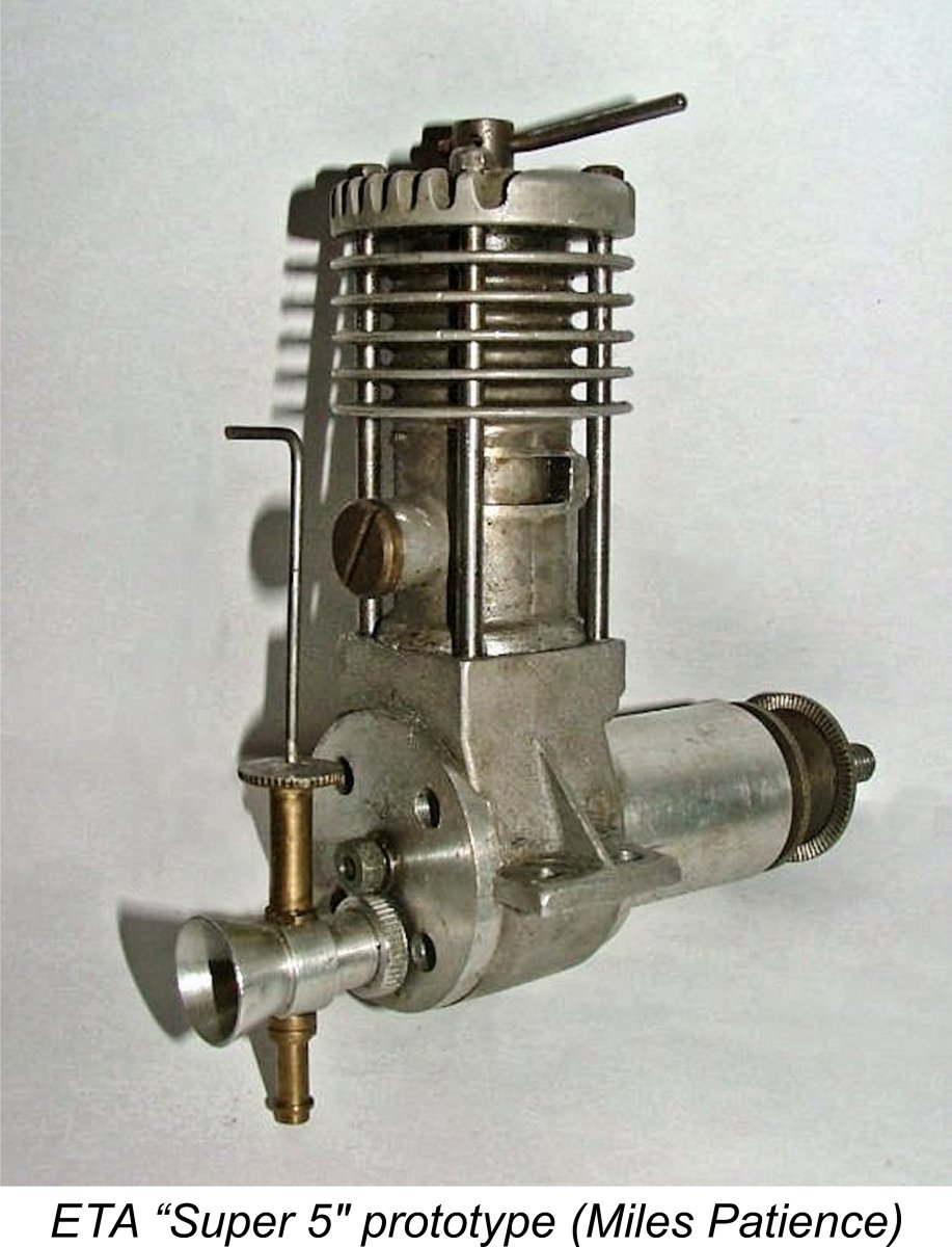 on schedule in the company’s advertisingplacement for that month. Instead, the big news announced in the ETA ad for June 1948 was the availability of the 1948 ETA “5” CI engine which was said to feature improved porting which increased available power at higher RPM with no sacrifice of dependability. As matters stand, I’m unaware of the form which this “improved porting” might have taken, never having had the chance to compare 1947 and 1948 models.
 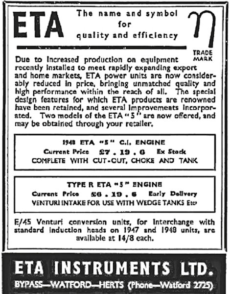 never made it into series production. Only a month later, in the July 1948 issue of “Aeromodeller” (left), ETA dropped all mention of the Super “5” model, instead announcing the availability of the somewhat simplified and lighter "R" sideport model at £1 less than the "C.I." engine. This version was distinguished by a red-anodized cylinder head and spinner as well as a shorter intake venturi with no attached fuel tank.
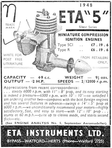 ETA "5" Silver Series. From the evidence to hand, this would appear to have absolutely nothing to do with the case finish, as the only "silver" engines with shiny cases of which I’m aware are earlier examples dating from 1947. It’s more likely that it relates to the 1948 implementation of the internal improvements mentioned in the earlier advertising.
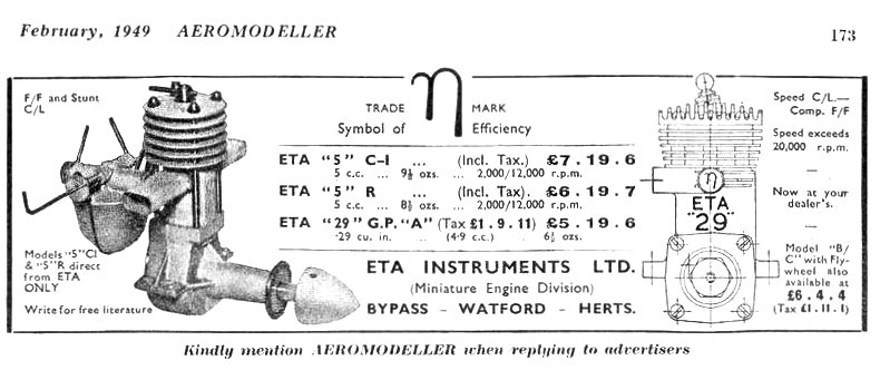 The ETA "5" continued to appear for some time in ETA ads even after the introduction of the more modern-looking, high-performance
 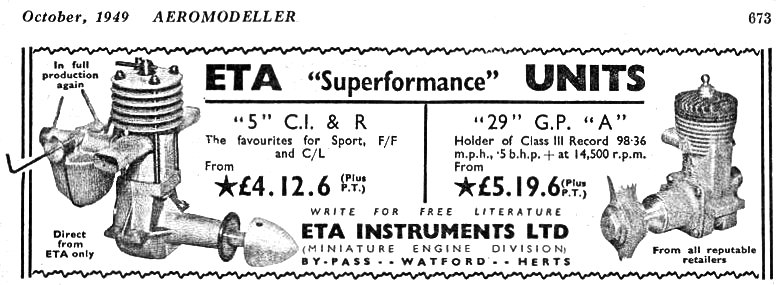 In reality, the suggestion of “full production” may have been a marketing smokescreen. Significantly, the 29 "G.P." was said to be available from your friendly local retailer, but the "5" was now "Direct from ETA only", and was being offered at a price of only £4 12s 6d (£4.63), a massive price reduction of £3 7s 0d (£3.35) representing a 42% price decrease! This appears to confirm that ETA had decided that the day of the big 5 cc side-port diesel was done and had almost certainly ended production, focusing instead upon clearing out its remaining inventory of the engines. Since the dealers were no longer interested, ETA were doing so through direct sales, perhaps converting their spares into engines as well.
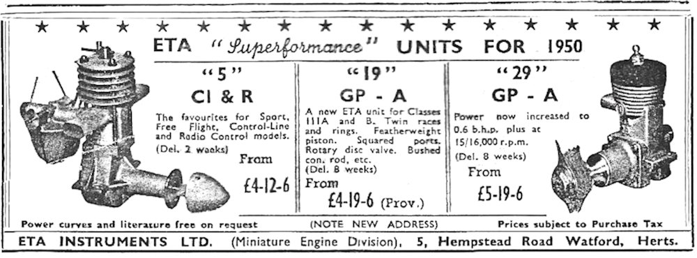 Promotion of the ETA “5” finally ended altogether in early 1950 as demand dried up completely and the glow-plug models came to dominate the ETA sales picture. The last appearance of the ETA “5” in a company advertisement came in the May 1950 issue of “Model Aircraft”.
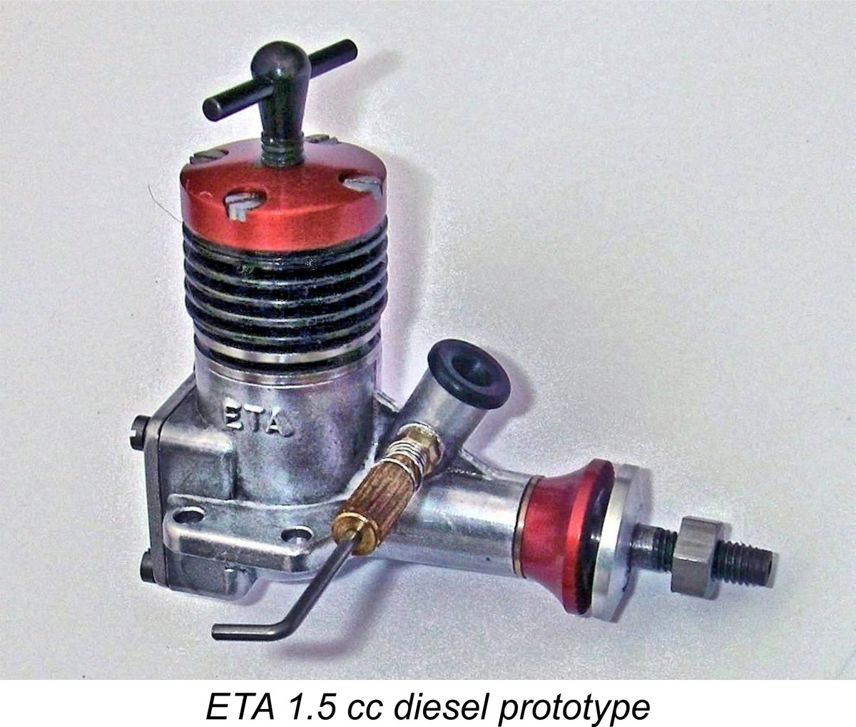 Eric Bedford doggedly continued to pursue the development of diesels on his own, producing a design for an excellent 1.5 cc radially-ported FRV diesel in late 1950 after the company’s abandonment of the ETA “5”. This engine displayed a certain degree of stylistic influence from the OK Cub models from America. ETA Instruments completed a few prototypes, one of which was later submitted to Dennis Allen to assess as a possible subject for licensed larger-scale mass production than ETA were then able to contemplate. However, for reasons which remain unclear the design was not pursued.
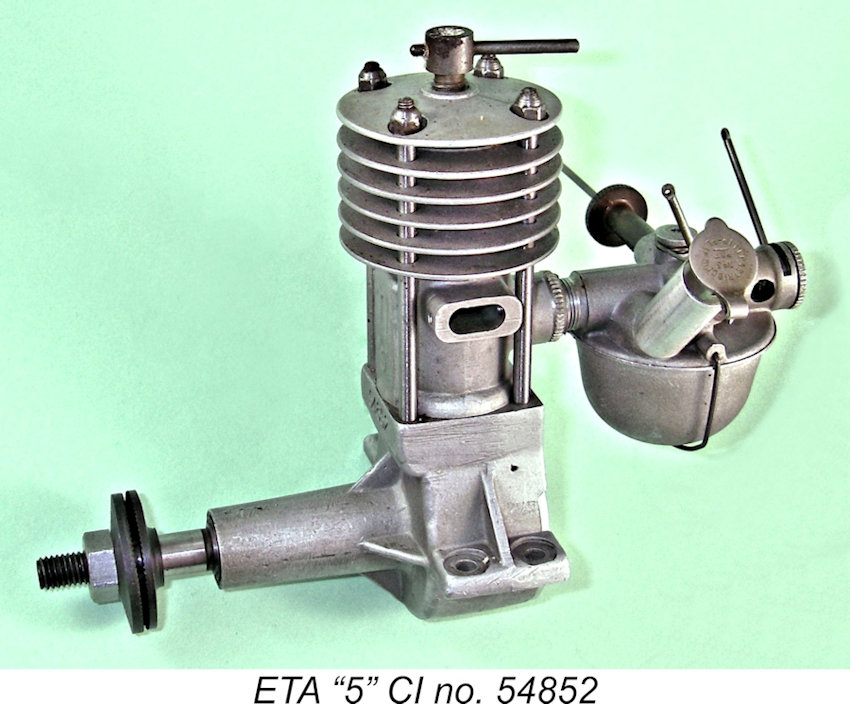 The ETA "5" has a delightfully “vintage” look about it - the very “tall” appearance, long exposed cylinder studs, cast tapered fins and the mysterious garden of tubes and levers growing out of the carburettor all contribute to this overall impression. Underneath all of the apparent complexity, the engine is actually a conventional long-stroke side-port plain-bearing compression ignition engine. Bore and stroke are 17.06 mm (0.672 in.) and 21.83 mm (0.859 in.) respectively for a displacement of 4.99 cc (0.305 cuin.). Checked weights are 283 gm (9.98 ounces) for the standard CI tank-equipped version and 272 gm (9.59 ounces) for the tankless R variant.
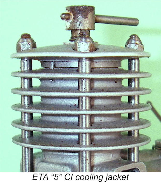 The steel cylinder liner is a shrink-fit in the cooling jacket, protruding at the bottom to form a spigot that fits into the crankcase. The cast cooling fins taper towards their edges and have rounded tips and gap roots for optimum thermal dissipation in the finest
 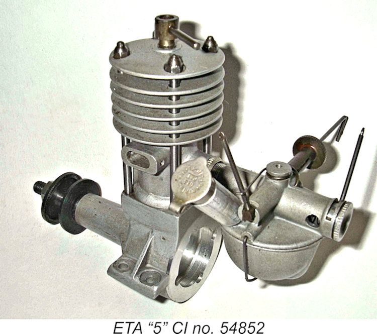 This arrangement works fine provided that the fuel mix used in the field is the same as that used at the factory! It also frustrates the clearing of a flood by backing off the compression significantly - annoying!! Note that there is no "correct" stud for the compression-stop nut. It will have been factory-selected for each engine by one of the factory inspectors following the engine's test run. Many users replaced this extended nut with a standard short nut, thus restoring the full range of compression adjustments for convenience. My own two examples have both been modified in this manner.
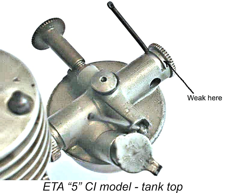 One of the features which endears the tank-equipped CI version of the ETA “5” to many collectors and diesel fanciers is the assortment of tubes and levers on the tank top. The engine inducts its air through two opposing holes in the sides of the rear-facing venturi rather than through its outer end in the usual way. A spring-loaded rotary plug in the end with matching holes serves as a rotatable choke, actuated by the lateral operating lever to provide a degree of speed adjustment. The fore-aft acting spring-loaded lever in the middle operates a cut-off that closes off the fuel supply and is biased to the "run" position.
 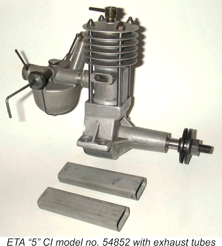 The fuel tank is a complex aluminium stamping retained by an under-slung spring clip. A central depression provides a sump-like fuel pick-up area to the rear. Lawrence Sparey called this the ETA "last drop" container. A long filler tube with a spring cap completes the inventory of things sprouting from the assembly. All of this delightful complexity threads into a boss at the rear of the cylinder casting and is locked by a knurled ring, allowing it to be rotated for inverted running.
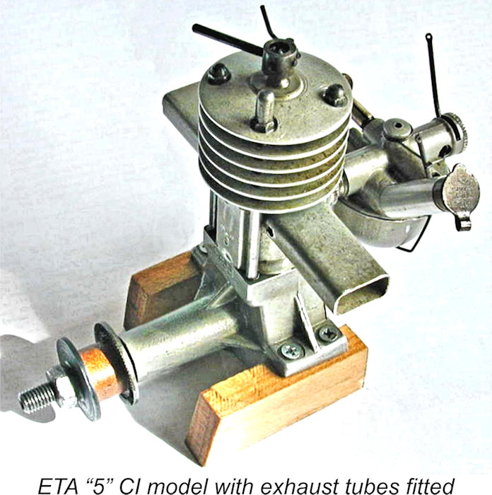 The prop driver is turned from steel and fitted to the shaft on a simple stepped shoulder. Most unusually, its annular orientation is secured solely by the pressure of the prop nut pushing the driver against the step, since no taper is incorporated. This was an ETA safety measure intended to allow the driver to turn on the shaft in the event of a "sudden arrival", thus minimizing the potential for damage to the working components in such an unhappy eventuality.
 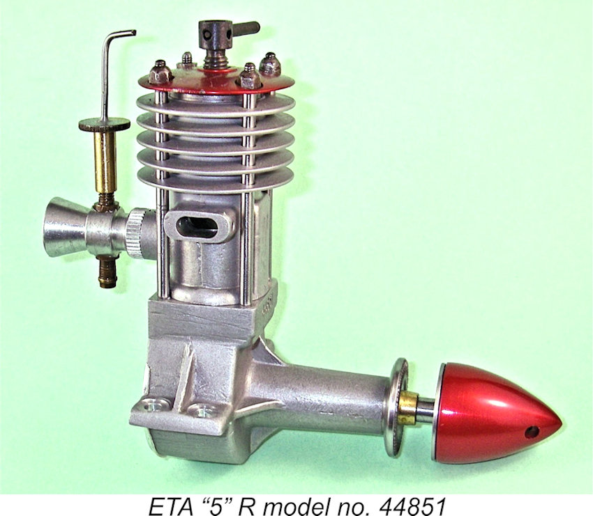 The maker’s recommended fuel mixture was a blend of 3 parts ether, 2 parts gas oil (a form of kerosene) and 1 part Castrol XL mineral oil (SAE 30). To me, this seems to be a bit light on the oil content. That said, users report that the engine runs perfectly well on any latter-day diesel mix.
 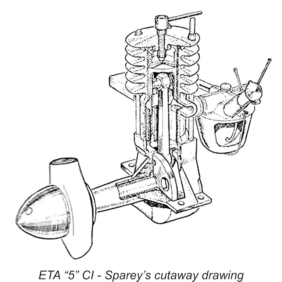 The ETA "5" was the subject of “Aeromodeller's”
 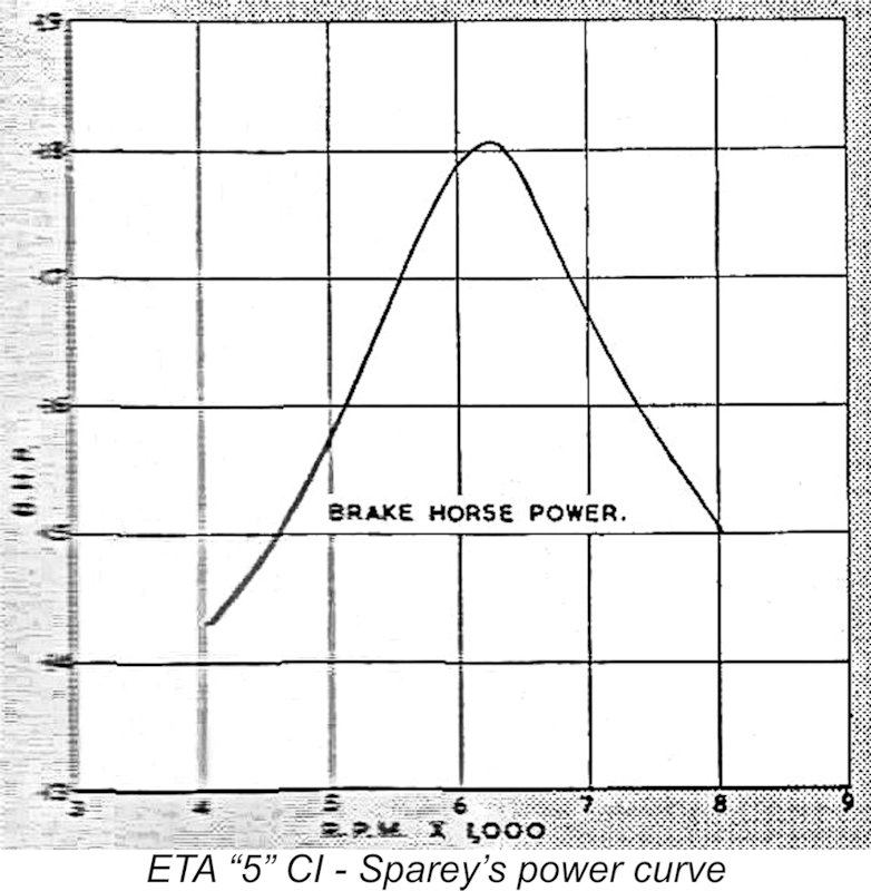 In this context, Sparey made one remark which seems to me to shed some light upon his possibly flawed views regarding engine performance. He stated that “in one respect the ETA would seem to be well designed, in so far as the engine seemed most happy when running at speeds around that at which the maximum BHP was delivered”. Really?!!? Why would you expect otherwise? Engines invariably run best at and around their peak precisely because that’s inherently the speed at which their various operational processes combine most effectively! The suggestion that the ETA was designed to run best around a specific peak speed at the cost of indifferent performance at other speeds is manifestly absurd! A clear case of confusion between cause and effect………….
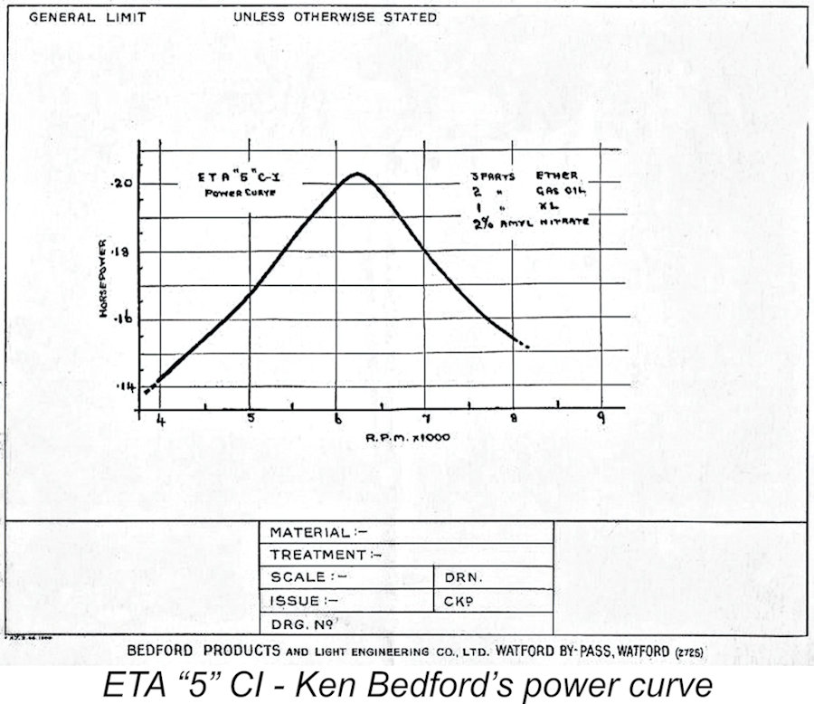 Some quite persuasive support for the validity of Sparey’s findings comes from the power curve developed for the ETA “5” by ETA Instruments themselves using a testing dynamometer constructed by Ken Bedford. This power curve was preserved in the estate of Eric Bedford, subsequently being rescued from oblivion by my good friend Miles Patience. It has almost exactly the same shape as the curve published by Sparey, and the Bedford brothers certainly knew how to test a diesel! The peak output indicated by their testing was 0.203 BHP @ 6,200 RPM.
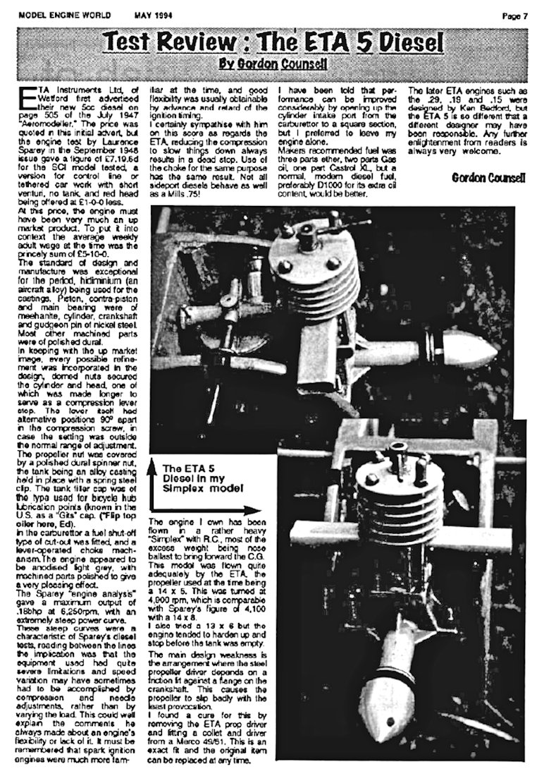 Decades later, the ETA “5” was the subject of a retrospective test by Gordon Counsell which appeared in “Model Engine World” (MEW), Volume 1, Number 1, May 1994. Gordon confined his report to a general description of the engine’s construction plus a summary of his own experiences using the engine in a 60 in. span “
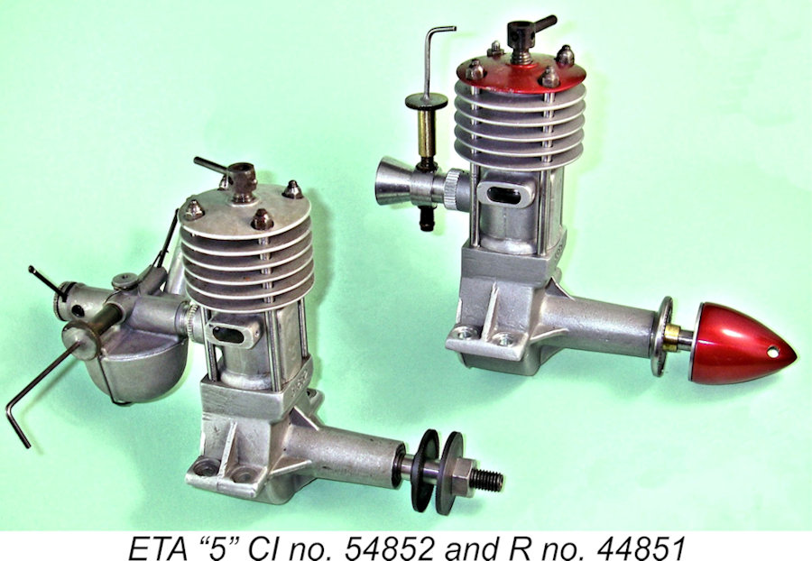
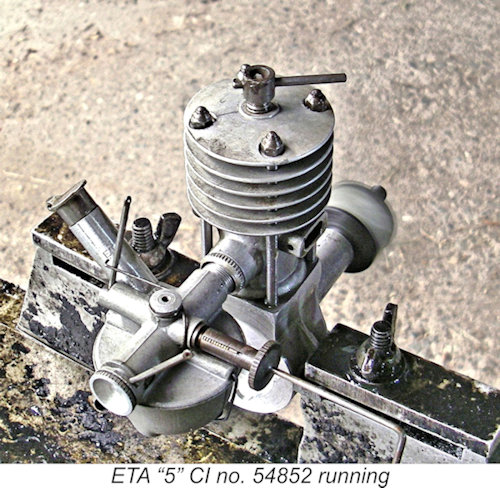 First into the test stand was ETA “5” CI no. 54852. For these tests I used a fuel containing 35% kerosene, 35% ether and 30% SAE 60 mineral oil (AeroShell 120) with 1% cetane booster added to the overall mix. Most large sideport diesels run well on such a brew, while the high oil content is very kind to the wearing surfaces.
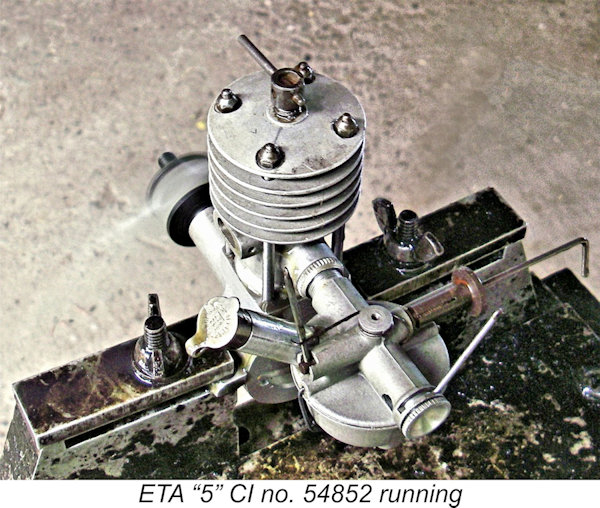 I put five tankfuls of fuel through the engine, confirming that it ran for around 2½ minutes on a full tank as reported by Dick Roberts. Having confirmed this running time, I then adopted a practice of leaning the engine out at around 2¼ minutes in order to subject the piston/cylinder components to the full-range heat cycles which are so necessary for a proper
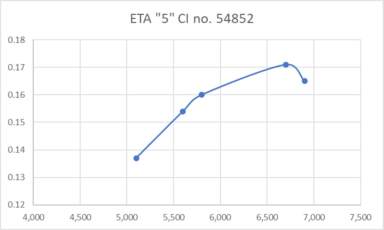
| |