
|
|
The ETA 29 (and 19)
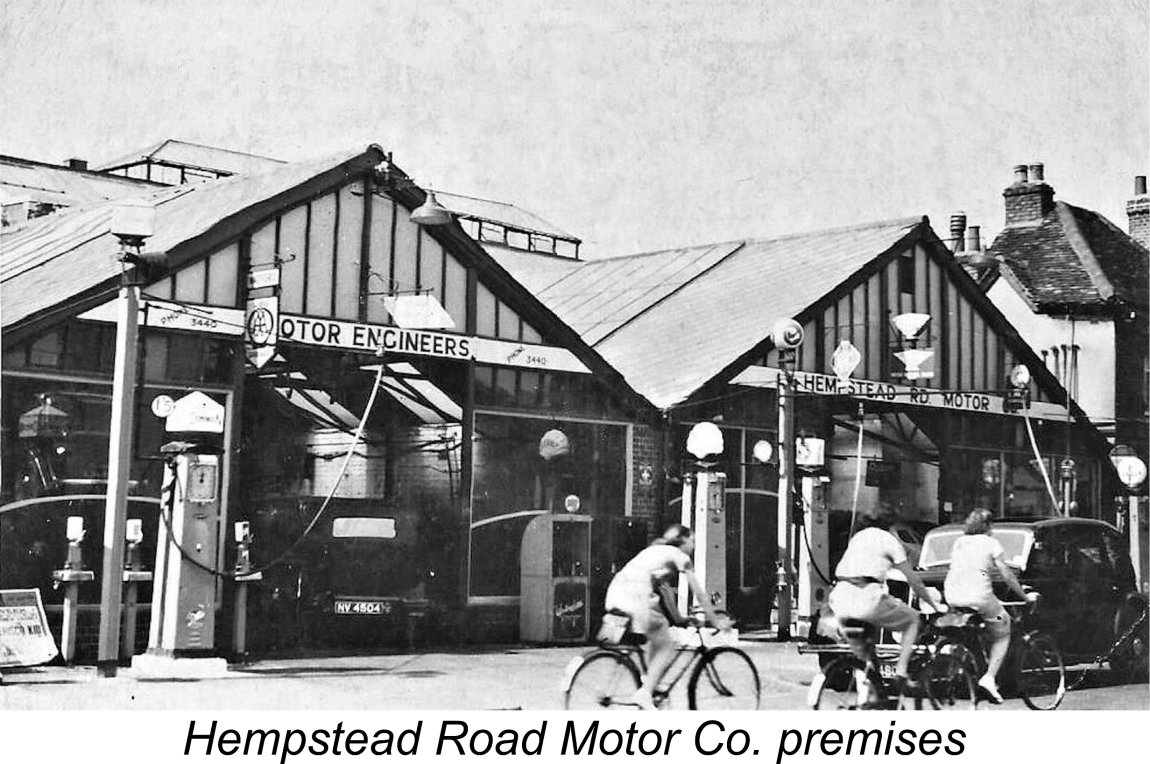
Before getting started on this task, it’s both a duty and a genuine pleasure to present a summary of my sources, along with a few appropriate acknowledgements. First and foremost, I must pay tribute to Martyn Serginson, who Secondly, it would be hard for me to overstate my indebtedness to former Championship-level Class ”B” team race icon Ray Tuthill. Ray was kind enough to share many reminiscences of his time using the ETA 29 to such good effect in Class “B” competition during the mid to late 1950’s and early 1960’s. Having been involved very directly with Ken Bedford in the transformation of the ETA 29 into its final fully-developed configuration, Ray was in the best-possible position to supply authoritative information from the inside. Thanks, mate!! Many of Ray’s reminiscences may be found on John Lichnerowicz’s fascinating website which is devoted to a range of modelling-related subjects, including the ETA engines. Much of Ray’s information to be A third source of information came in the form of Malcolm Ross’s tribute to Ken Bedford which appeared in “AeroModeller” magazine following Ken’s death in January 2015. As a long-time friend of Ken’s, Malcolm was able to provide a great deal of background information both on the Bedford family and on the ETA venture in general which would otherwise have been lost. We’re all very much in Malcolm’s debt. Another valuable contribution came from Ken Bedford's son Lyndon Bedford, who provided several very informative serial numbers as well as some extremely useful comments. I'm most grateful to Lyndon for his support and assistance! Finally, I must mention the ETA 29 article which may still be found on the late and much-missed Ron Chernich’s ”Model Engine News” (MEN) website. Although that article did not provide much in the way of new information, Ron’s personal views and insights with respect to the ETA 29 were nonetheless extremely valuable. Now, having acknowledged my sources along with my grateful thanks, it’s time to get started. As ever, I’ll begin by setting the stage. Background Before embarking upon this section of the article, I must acknowledge my indebtedness to Lyndon Bedford for the provision of many background details which he alone could provide. In addition, Lyndon shared a number of images which greatly inform this portion of the narrative. Remarkably enough, it’s possible to trace the roots of the ETA model engine story all the way back to WW1! In 1916, the tides of war brought Charles J. Bedford to England from his native New Zealand. While in London he met an English lady who eventually became his wife. Following the conclusion of WW1, he and his new bride moved back to New Zealand with the intention of staying there permanently. The couple started their family there, producing two sons, Eric (b. 1920) and Ken (b. 1924), both of whom were born in New Zealand. Charles Bedford opened a garage with an engineering shop in the rear in Turua on New Zealand's North Island. If the family had remained in New Zealand as originally intended, we would probably never have heard of the ETA model engine range! However, circumstances soon arose which resulted in a return to England. Firstly, the new Mrs. Bedford had difficulty adapting to life in New Zealand. This wasn't a positive factor, but the real crunch came in 1926 when Charles Bedford's premises in Turua were completely destroyed by fire. Upon arrival in England, the mechanically-minded Charles Bedford resumed the business that he knew so well, opening a motor garage on Hempstead Road in Watford, a town located in Hertfordshire a little to the north-west of London. The business was identified as the Hempstead Road Motor Company. Charles bought a house in Ilford, very distant from his place of business. This was a rather strange location for his residence, since it required him to make a 35 mile journey each day to get to work, and the same again back at the end of the day. He only resolved this awkward situation shortly prior to the commencement of WW2 by purchasing a house in Oxhey, very near to the garage location in Watford. Incidentally, as of 2012 after the passage of some 65 years, this garage still existed, although it had then changed hands many times. During the latter part of the 1930’s the business grew and prospered, prompting a move of the precision engineering operations into far larger factory premises on Colonial Way off the Watford Bypass. When WW2 broke out, the family’s engineering operation at this location was at the height of its success. The members of the Bedford family were soon working flat out making precision parts for the war effort. Speaking years later to Malcolm Ross, Ken Bedford recalled that at one point there were over 250 employees and rows of machines making parts as accurately and carefully as possible, while German raiders were dropping bombs everywhere. Luckily the premises suffered only light damage throughout that period.
In addition to this, Ken had developed his artistic talents both as a photographer and a musician. He had become a highly proficient saxophone player, performing periodically with various big bands including the famous Ted Heath dance band. It was during the war years that Ken first met his future wife Dorothy at a fireworks party in Harrow. Someone asked if anyone could go and fetch her. Ken was the only one there with a car, so he obliged. He and Dorothy hit it off immediately and were together constantly from that time onwards. They married in 1945 and their first son was born in 1947, with my valued informant Lyndon following in 1950. The marriage was to last for the next 66 years until Dorothy’s death in 2011 following a stroke. After the war, most of the precision engineering work dried up more or less overnight, causing the business to contract severely. Nonetheless, the partners wished to continue their former activities in the field of light precision engineering. They established a new precision engineering venture trading under the company name of ETA Instruments Ltd.
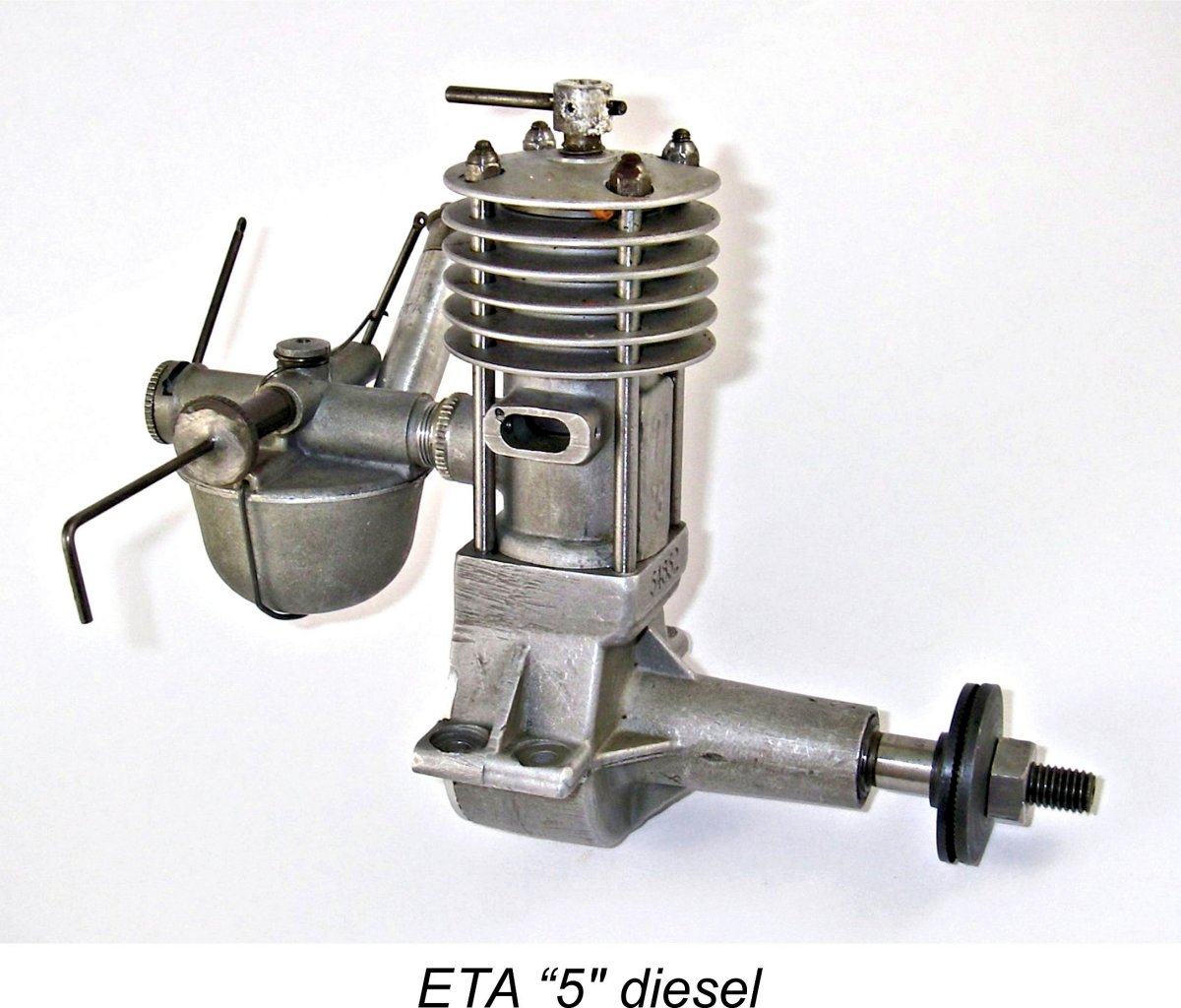
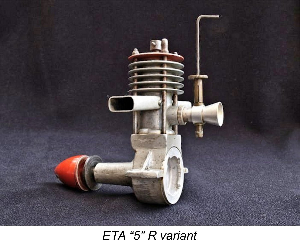
When the new ETA venture was started, it would appear that the Bedford family had a considerable stock of blank drafting sheets which bore the former company name of Bedford Products and Light Engineering Co. Ltd. It's certainly true that drafting sheets bearing this name continued to be used for the company's design drawings well into the 1950's - very thrifty!! As 1947 approached, the burgeoning popularity of power modelling in Britain at this time coupled with a strong family interest in the hobby led the Bedfords to decide to expand their production activities into the field of model aero engine manufacture. A “Miniature Engine Division” of the ETA company was quickly established, with its activities evidently being located initially "in the back room" at the Watford Bypass location, since the business address at this time was specifically given in the advertisements as being on the Watford Bypass. The first product of the new model engine venture was It has long been thought that the ETA "5" first appeared in mid 1947, since it was first advertised in July 1947. However, Lyndon Bedford has produced irrefutable evidence in the shape of engine no. 124614 that the ETA "5" was in existence as of late 1946 - that serial number identifies this example as the 14th unit produced in December 1946. It seems that the Bedfords only began to advertise this engine nationally after a trial period of selling it locally through model shops or by word of mouth. Its success evidently gave rise to their expanded marketing ambitions. The ETA “5” was designed primarily by Eric Bedford. The engine was a good runner, albeit somewhat inflexible in terms of its operational speed range. It was noted for its fine workmanship and for the excellence of its castings at a time when many British "garden shed" products lacked such positive attributes. The standard “CI” version had a tank and cut-out as illustrated here, but in mid 1948 the engine also became available in a somewhat simplified and lighter “R” version for control-line and tether car applications which is seen below. This version was distinguished by a red-anodized cylinder head and spinner as well as a shorter intake venturi with no attached fuel tank.
An unusual aspect of the ETA venture was the fact that from the outset everything was made in-house. This included the high-quality castings for which the ETA engines were always noted. Father and younger son Ken produced the tooling, and the whole family were involved in the production side.
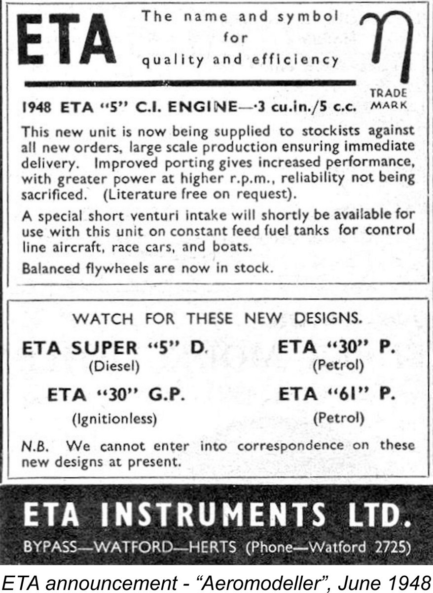
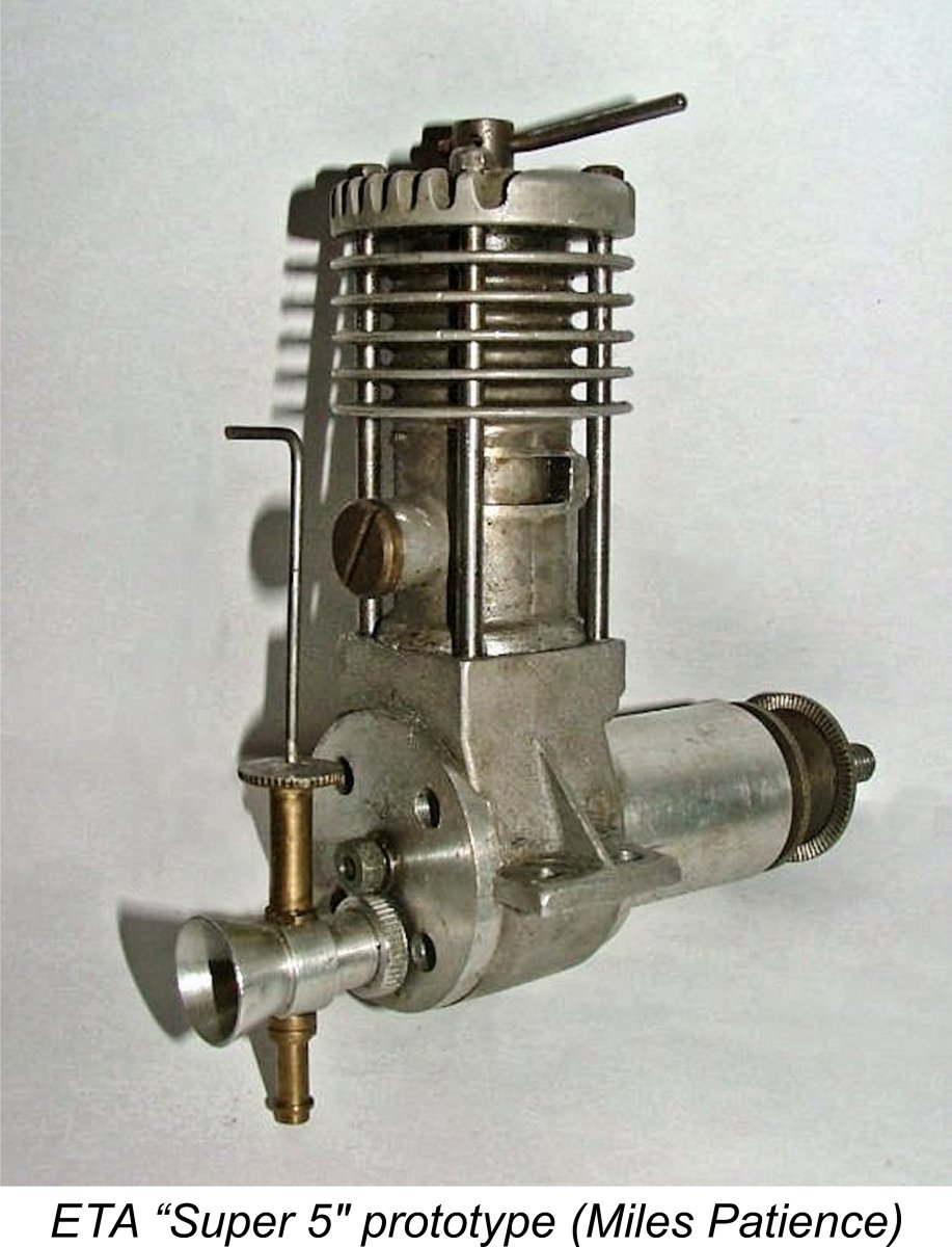
The then 24 year old Ken Bedford took due note of this development. At the time, he and older brother Eric had evidently been considering a variety of potential new model engine products. A somewhat enigmatic "teaser" advertisement which appeared in the June 1948 issue of “Aeromodeller” magazine mentioned a number of new designs which were then under consideration, including an ETA Super “5” diesel, an ETA “30” petrol engine, an ETA “30” GP glow-plug design and an ETA “61” As matters turned out, the “30” glow-plug model and the implied ETA "5" R model were the only listed designs to actually make a market appearance. The ETA "30" G.P. did so in the shape of the ETA 29 Model “A” (aka Mk. I) to be discussed in detail below. Evolving market conditions had evidently convinced Ken Bedford that the days of both large long-stroke diesels and petrol (spark ignition) engines were done and that a more promising future lay in the development and marketing of high-performance glow-plug engines.
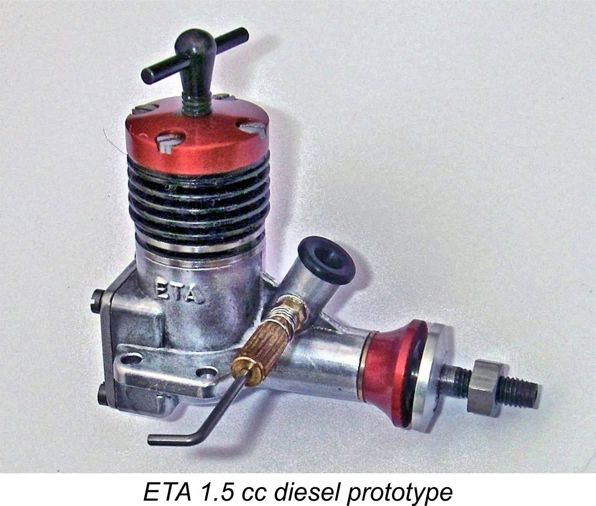
Eric doggedly continued to pursue the development of diesels on his own, producing a design for an excellent 1.5 cc diesel in late 1950. This engine displayed a certain degree of stylistic influence from the OK Cub models from America. ETA Instruments completed a few prototypes, one of which was later submitted to Dennis Allen to assess as a possible subject for licensed larger-scale mass production than ETA were then able to contemplate. However, for reasons which remain unclear the design was not pursued, although Peter Chinn somehow obtained an Miles and I got together in February 2017 to test Miles' own example of this engine, finding it to be a very good runner having a performance which was well above average for a 1.5 cc diesel of its era. We measured a peak output of around 0.170 BHP @ 13,200 RPM, implying significantly better-than-average torque development for an early 1950's diesel of this displacement. However, we also found the engine to be somewhat temperamental to start. Perhaps this was why the ETA 1.5 never saw production………… Returning now to mid 1948, Ken Bedford was of course very much aware of the fact that the Americans had quickly leapt out to a wide lead in the glow-plug motor design department. This forced any British manufacturer who wished to challenge them with a domestic product to more or less follow in their footsteps, at least initially. A number of British firms such as Nordec, Ten-Sixty-Six and Rowell had already produced American-influenced racing models to (unsuccessfully) challenge the American designs, although all of these efforts had been in the 10 cc class.
The family tradition of keeping everything in-house was continued with this new model, since Ken Bedford actually did all of the pressure die-casting himself. The only components not manufactured in-house were the piston rings and the ball races. Ken always took a very rational engineering approach to his design work, preferring actual measurement and hard data to the seat-of-the-pants approach adopted by many others. From the start, he maintained his own dynamometer apparatus on which he was able to directly measure and record the effect of the various modifications to which his designs were subject over the years. Accordingly, all of the various improvements which were applied to the ETA 29 over the years were thoroughly tested by Ken prior to release to the public. Having examined the genesis of the ETA 29 racing engine, it’s now time to take a close look at the design variations which were applied to this model over the years. I’ll begin with a general description. The ETA 29 - general description
The piston was fitted with two conventional Meehanite piston rings running in a hardened Meehanite cast-iron liner. The rings were manufactured by Wellworthy under contract to ETA. Both front and rear covers were detachable, being secured by four screws each. Prop mounting was accomplished using a bobbin-style prop driver in conjunction with a steel sleeve nut. This was pretty much the established racing engine “formula” of the day, having been pioneered in the USA by such manufacturers as Hornet, McCoy and Dooling and followed in Britain by Nordec, Rowell and Ten-Sixty-Six. Bore and stroke of the ETA 29 were 0.750 in. (19.05 mm) and 0.672 in. (17.07 mm) respectively for a displacement of 4.87 cc (0.297 cuin.). These figures were maintained throughout for all models. Weight varied a little between versions, but generally hovered around the 205 gm (71/8 ounce) mark.
All variants used a two-piece fuel metering system with a screw-in surface jet supplying the fuel on one side of the intake venturi and a needle projecting through a stub carrier on the opposite side and traversing across the venturi bore to control the rate of fuel entry into the induction system. This was a very free-breathing arrangement since only the needle itself interrupted the induction airflow rather than a far thicker spraybar. This set-up had been introduced in the USA by the Hornet, McCoy and Dooling racing engines and was widely adopted by racing engine designers worldwide. The design details of the actual components applied to the ETA 29 underwent some changes as time went by, but the basic system remained unaltered. One of the attributes of the ETA 29 which set it apart from many of its ringed-piston competitors was the general excellence of the seal provided by the rings even in a brand-new engine. Peter Chinn commented particularly upon this point during his May 1954 test of the ETA 29 Mk. III (see below), stating that while any ringed-piston engine needs a little running to bed the rings in properly and produce a really good seal, the ETA was in his opinion better when new than most “transatlantic products” that he had experienced, some of which required a castor oil prime to generate an adequate compression seal for initial starts. As stated earlier, throughout the almost 20-year production life of the ETA 29 the overall appearance of the engine changed surprisingly little, particularly from the Mk. III variant onwards. Accordingly, the greatest challenge in assessing examples of the engine that may come up for sale is that of model identification. Many of the changes were internal, requiring that the engine be at least partially dismantled for confirmation purposes. This is of course highly problematic in the case of engines offered for sale on venues such as eBay where direct pre-sale examination is not possible. Moreover, it's never a good idea to disturb an engine that is well run-in and settled down.
The numbering system applied by ETA was strangely inconsistent between models, seemingly changing almost every time a new Mark was introduced. However, this has some unquestionable advantages in terms of model identification, since all examples of a given model seem to have been numbered in a manner that was at least consistent with other examples of the same model. As a result, confirmation of the serial number on a given crankcase does at least identify the model into which that case was originally incorporated, although the interchangeability of parts between some models means that the serial number alone does not guarantee the complete originality of a particular engine. Many examples are seen with mis-matched parts based on their serial numbers. In his previously-mentioned article on the ETA 29 which appeared in issues 65 and 66 of “Model Engine World”, Martyn Serginson covered all the various forms in which the engine appeared on the market over the years. Martyn's piece gives the dates, identifying features, rarity and background for each model in great detail. Those interested in obtaining more information than I intend to present here are highly recommended to that article.
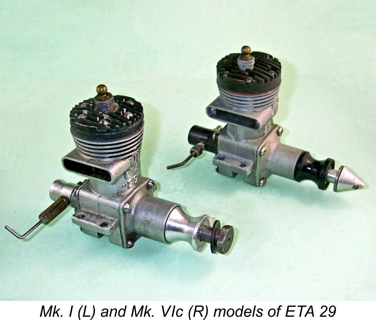
At this point, it’s hard to know what to call the engine – even ETA themselves appear to have had difficulty making up their own minds! If we give the tie-breaking vote to the advertising, we find that the engine continued to be identified as the ETA “29” GP (presumably standing for glow-plug) in the company’s advertising until midway through the production period of the third variant of the engine. At that point, the name was finally changed to the ETA 29 Mk. III. This variant of the engine was tested by Peter Chinn under that name in early 1954, as reported in more detail below. For consistency, I have elected to use the Mark system of identification throughout in order to clearly position each variant within the overall series. It does however need to be pointed out that this identification protocol does not fully represent the sequence followed by ETA themselves. With the above background in mind, I’ll now attempt to present a summary of the evolution of this engine. In doing so, I’ll stress the differences that have been found to assist in model identification. ETA 29 Mk. I (aka “Model A”) – February 1949 to mid 1950
The first national advertisement for the new model appeared in the February 1949 issue of “Aeromodeller” magazine alonside the ETA "5" diesel which remained in production in both its C-I and R guises. The quoted selling price of the ETA 29 was £5 19s 6d (£5.97) inclusive of all taxes. The manufacturers identified themselves as ETA Instruments Ltd. (Miniature Engines Division), Bypass, Watford, Herts. Evidently at this stage the engines were still being manufactured in the “back room” of the factory at that location!
The other positive identification feature was the fact that the Mk. I featured a front bearing housing which had an external diameter of 0.850 in., somewhat larger than those seen on later models. The crankcase featured a bypass passage which had vertically parallel sides with no "bulges" at the top, as seen in the earlier image of the bypass on engine number 30477. In addition, the exhaust stack featured a thin vertical pillar in its centre, presumably to enhance the stability of the casting when in service. The cylinder head featured a centrally-located glow-plug which was angled towards the transfer side. The effect of this was to offset the element slightly towards the transfer side, presumably to speed up the involvement of the pocket of gas behind the piston baffle in the combustion process.
The pressure die-cast aluminium alloy con rods used in the earliest examples of the engine were bronze-bushed at the big end only. They quickly proved inadequate for the task, suffering an unacceptable rate of failure. The rod in Ray Tuthill’s original ETA (probably a Mk. II as far as he could recall) was one of the many which broke. Ray recalled that the break revealed considerable porosity within the casting. He sectioned another rod, which turned out to display the same shortcoming. It appears that the ETA rod castings were below the required standard. The McCoy rods were light alloy forgings, a far more appropriate material and method of production. After that failure Ray never used the cast ETA rods again in any of his engines. Instead, he machined his own rods from extruded dural stock and fitted them with pressed-in phosphor bronze bushings at both ends. They were thus both lighter and stronger, even though profiled to an elliptical section. None of Ray’s home-made rods ever broke.
The serial numbers for this first model all start with "3", followed by four (sometimes three) additional digits which presumably indicate the position of the engine within the production sequence. The earliest example which has come to my attention is Lyndon Bedford's engine no 3105, making it the 105th unit to be manufactured. My own illustrated example bears the serial number 30477, seemingly making it the 477th example of this model to come off the line. Martyn Serginson reported the existence of engine number 3787 of this type, indicating that as many as 800 examples may have been made in total. However, so many of these were modified by their owners, including the substitution of parts from later variants, that complete and original examples in good condition are extremely rare today. This variant was the subject of a test conducted by Lawrence H. Sparey which appeared in the September 1949 issue of “Aeromodeller” magazine. This test report is reproduced below.
Sparey was very impressed with the engine’s finish, handling and performance, characterizing the measured output of 0.370 BHP @ 11,600 rpm as “exceptional for an engine of this capacity”. He did however confirm the previously-mentioned weakness of the con-rod, since he was forced to install a new rod twice during the course of his testing. In part this may have been due to Sparey’s inexplicable habit of testing racing glow-plug engines with their very narrow ignition timing range at speeds far below those at which the ignition timing might be anywhere close to correct. Running a racing engine like the ETA down to 6,000 rpm under load (as Sparey did) is bound to impose greatly exaggerated stresses on the rod due to the inevitable pre-ignition at such speeds.
Note that the shape of Ken's curve is quite different from that published by Sparey. Moreover, the engine is referred to on the sheet as the ETA "29" GP Series I, a designation which was never publicly applied to the engine. Finally, note also that this power curve was drawn up on a sheet of drafting paper which continued to bear the original company name of Bedford Products and Light Engineering Co. Ltd. In all honesty, I have to say that the performance of my own example of this model seems far more in line with Ken’s figures than with those published by Sparey. My engine is a quite lively performer, although concerns regarding the integrity of the original rod have dissuaded me from subjecting it to the rigors of an all-out test.
Whatever its true performance, the engine got off to a very good start by taking the Class III speed event at the major 1949 Dover meeting with a speed of 97.84 mph. In their advertising, ETA Instruments made much of the fact that this was the outright fastest speed recorded at this meeting in any class, including the 10 cc entries. Clearly Fred Carter with his 116 MPH + "Little Rocket" powered by a reworked Nordec RG10 was not present on this occasion! After the production of the ETA 29 Mk. I had got underway, Ken Bedford turned his attention to the development of a smaller version of the same basic design in the shape of the Mk. I ETA 19. This engine appeared in early 1950 to join its larger relative in the ETA range. I’ll cover the ETA 19 below in a separate section of this article.
At some point in the latter part of 1949, ETA Instruments Ltd. finally accepted the fact that their premises on the Watford Bypass no longer matched their needs. A new manufacturing facility was therefore established at 289 High Street in Watford. The former facility on the Watford Bypass has since survived to become the main regional sorting facility for the Post Office, although it has been extensively remodelled in association with this change of use. The replacement facility on High Street has also survived, serving today as a furniture warehouse. Lyndon Bedford advised that the High Street facility was completed during 1949. However, for reasons which are now obscure, the company's advertisements from early 1950 until early 1952 cited their address as being 5 Hempstead Road in Watford, characterising it as their "new address". This may well have been associated with the family garage operation, which was evidently still owned by the partnership. It appears that the manufacturing and business activities were being kept separate at this time. It was from the Hempstead Road address that the next variant of the ETA 29 was promoted. ETA 29 Mk. II - Mid 1950 to Nov. 1950 In mid 1950 the Mk. II variant of the ETA 29 made its appearance, although it was never referred to as such by its manufacturers. By this time, the business address of ETA Instruments had been relocated to Hempstead Road, accordingly dropping the “Bypass” address and giving their location as 5 Hempstead Road, Watford, Herts. They had also ended production of the old ETA "5" diesel, concentrating for the next nine years upon the development of their glow-plug models. The main externally-visible change that distinguished the new Mk. II variant (as I will call it) of the ETA 29 was the revised design of the backplate, which now had an intake venturi which was cast integrally with the backplate itself, thus eliminating the former plug-in component. According to Peter Chinn, the revised venturi had a 25% greater effective choke area than its predecessor. The revised casting was not anodized at this stage, being left in its as-cast state apart from some surface clean-up. Apart from the power increase which resulted from the greater choke area, this design change may represent a response to issues with the plug-in component working loose during extended high-speed operation. The new model also featured the beefed-up rod which had been developed in response to the problems which had manifested themselves with the original Mk. I variant. Otherwise, the Mk. II was identical to its Mk. I predecessor. The alloy rotor disc was retained along with the same cylinder head and large-diameter front housing. The needle valve too continued unaltered. The changes may have been relatively minimal, but it seems that they did have some effect in terms of boosting performance. Peter Chinn later recalled that the changes which were introduced to create the Mk. II version had boosted peak output by around 15%, with an increase in peaking speed of between 1,000 and 1,500 RPM compared with the figures for the original Mk. I variant. This must be down to the revised backplate design with its 25% greater effective choke area.
The above view is supported by the fact that the factory serial number sequence was continued without a break when the revised design was introduced. The serial numbers continued to start with "3" followed by the number of the particular engine in the series. This sequence was continued consecutively from that established with the Mk. I in order to avoid duplication of numbers. Apart from the higher serial numbers which necessarily resulted from this continuity, the defining features of the Mk. II ETA 29 are the one-piece backplate allied to the large-diameter front housing - a unique combination among ETA 29’s. During 1950 the Mk. I and Mk. II ETA 29’s between them added greatly to the engine’s already-impressive string of competition successes, winning major contests in Britain and elsewhere. A noteworthy Moreover, the ETA 29’s success was by no means confined to the various racing categories. Although designed primarily as a racing engine, owners soon discovered that if fitted with a spraybar in place of the standard surface jet needle valve assembly, the ETA 29 made a surprisingly useable control-line stunt engine. The ETA’s effectiveness in this application was underscored in 1950 when it took first places in both Junior and Open stunt at the 1950 New South Wales Championship meeting in Australia. Consequently, the ETA appeared as the plan engine on a number of published Aeromodeller Plans Service control line stunt designs of this era, including Eric Higlett's illustrated "Hopit" which was published in the March 1951 issue of "Aeromodeller".
Nothing is known about this engine apart from its likely date of late 1950/early 1951. This date is based upon the fact that it uses an unnumbered case of the type used with the Mk. III variants (see below) having a parallel-sided bypass passage with small "bulges" added externally at the top of the bypass. The diameter of the cooling fins above the exhaust stack has been neatly reduced by turning in a jig, and the exhaust stack has been equally neatly shortened. The cylinder head is a revised casting having no cooling fins. The plug is vertically oriented in this head rather than being angled as on the standard model. The front housing is also an all-new die-casting, implying that Ken Bedford had serious thoughts of going further with this variant – no barstock prototype here! He may have been contemplating providing some more focused competition for FROG and Yulon in the 5 cc control line stunt field.
This example retains the large-diameter front housing, the unanodized backplate, the integrally-cast large diameter rear intake, the straight-sided bypass with no upper "bulges" and the stiffening column in the exhaust stack which together characterize the ETA 29 Mk. II. However, it bears the serial number 29177, which places it early in the numbering sequence applied to the following ETA 29 Mk. III to be described next. The needle valve assembly features a conventional spraybar in place of the surface jet assembly generally fitted, implying that the envisioned use of the engine was in stunt service. However, the needle itself is the same one used in the Mk. I and Mk. II models. In addition, the cylinder cooling fins above the exhaust stack have been very neatly turned down along with the cylinder head, very much along the lines of the turned-down fins seen on the previously-illustrated FRV "special", although the head on engine number 29177 is a modified standard component complete with original black anodizing, angled plug and integrally-cast cooling fins. The exhaust stack has also been very neatly shortened, again exactly like the FRV example. It seems possible, albeit completely unproven, that this is another "special" created by the factory for a customer or associate to try out in the field in control-line stunt service. The fact that it showed up in New Zealand may be significant - the Bedford family was from New Zealand, remember. They doubtless retained contacts there and may have wished this field trial to take place far away from prying British eyes!
The needle valve assembly is perfectly matched to the venturi, looking as if it was made for it rather than being an owner add-on. In fact, the whole engine looks far more like a factory initiative than some owner's after-purchase modifications, although naturally this cannot be proved. It has undoubtedly received a fair bit of use, but remains in perfect mechanical condition with excellent compression. It starts and runs extremely well on the bench, with good suction and excellent needle response. Having said all of the above, this engine's serial number remains a real enigma. To all intents and purposes, it's a Mk. II which has been modified for stunt service. So why the serial number in the Mk. III sequence?? Only the factory could have put that Mk. III number on what is unquestionably a Mk. II case, implying that the factory did indeed have something to do with the creation of this particular variant. We'll amost certainly never know why they applied that number ............... All that I can say is that this may well be another experiment by the factory with a view towards creating a purpose-built control-line stunt version of the disc-valve ETA 29, which had already shown some promise in that field as noted earlier. The fact that the engine showed up in New Zealand (Ken Bedford's birthplace) may have some significance - it may have been sent to one of the Bedford family's compatriots to undergo field testing well below the British radar. Who ever said that sorting out the history of a model engine marque would be straightforward?!? ETA 29 Mk. III - Nov. 1950 - Aug. 1956
However, this latter feature was most likely a simple matter of using up existing castings, since the front housing was soon revised, presumably after the existing castings had been used up. Previously-discussed engine number 29177 (nominally the 177th example of the Mk. III) retains the large diameter front end, but by the time we get to illustrated engine number 329328 the smaller-diameter component has been introduced. The replacement front housing had a main bearing external diameter of only 0.750 in. as opposed to the 0.850 in. seen on the previous two models. The front ball race was correspondingly reduced in size from ¾ in. O/D to 5/8 in. O/D. This change was presumably a weight-saving measure. The quoted serial numbers suggest that the revised housing became a standard feature on new examples of the Mk. III from a relatively early stage of its production life - perhaps only the first few hundred examples retained the large-diameter component. The revised spare parts list which appeared in September 1951 was specifically amended to reflect the new component, which was to remain unchanged for all succeeding models. Another evident consequence of the desire to use up existing parts inventory was the early Mk. III's use of the same needle valve assembly as its two predecessors. As soon as the excess inventory had been used up, the needle valve design was changed from the former split-thimble needle to a McCoy-style externally-threaded needle with a split carrier and gland nut for tensioning. My own illustrated little-run example no. 329328 (engine no. 328 of the Mk. III series) is fitted with one of these later assemblies, together with the smaller-diameter front housing.
The purpose of the two external bulges at the top of the bypass passage is somewhat obscure given the fact that the internal configuration of the bypass was unchanged. Indeed, the top of the internal bypass passage was soon lowered to better conform to the revised location of the transfer ports (see below), thus further increasing the apparent redundancy of the two external bulges. My own best guess is that this was simply a means of providing more material at the always-vulnerable exhaust stack location to resist operating stresses upon the crankcase, hence decreasing the possibility of a fatigue failure. Such failures have been documented in connection with the Mk. I/Mk. II cases. The idea Internally, this variant featured minor revisions to the transfer ports, which were slightly enlarged. Perhaps more significantly, the port timing was also revised, with both exhaust and transfer ports opening later than before. This explains the lowering of the top of the bypass passage. In response to ongoing problems with con-rod failure, a further revised con-rod was used. This was still a cast item with bronze bushings at both ends but was now of significantly more massive dimensions overall.
It's interesting to note that this curve was captioned as applying to both the Mk. II and Mk. III variants of the engine. It would appear that Ken Bedford did not claim any significant performance increase for the Mk. III model. Rather, the changes appear to have been primarily directed at improving the engine's sturdiness and dependability. Note also that the company was still using drafting paper bearing the old Bedford Products designation! They must have had a good stock of that paper! This variant was the subject of a test by Peter Chinn which appeared in the May 1954 issue of “Model Aircraft”. Oddly enough, Chinn's test example was one of the early models with the larger-diameter front end which had certainly been replaced with the slimmer variant by the latter part of 1951. Chinn's example also had the Mk. I/Mk. II style of needle valve which had also been replaced quite early on. It seems that Chinn had somehow ended up with an early example of the engine for test. Too bad that he didn't record the serial number .........
Serial numbers for this variant start with the figures “329” or (later) just “29” followed by the engine’s individual number within the sequence. Another example of ETA’s inconsistency with respect to their serial numbers! The “3” used on the earlier examples of the Mk. III was evidently a carry-over from the earlier Mk. I and Mk. II models which was dropped fairly early on. My own illustrated example bears the serial number 329328, making it one of the earlier examples. It has the smaller-diameter front housing, as does similar engine no. 29462 which was illustrated by Martyn Serginson. I am also aware of similarly-configured engine number 29484. I suspect that ETA simply used up their existing stocks of the original front ends before equipping all subsequent examples with the revised assembly. Between them, these numbers imply that the dropping of the “3” from the serial number occurred between engine numbers 328 and 462, probably at the beginning of the year 1951. The same logic applies to the short-term use of the Mk. I/Mk. II needle valve assemblies.
The “standard” version of the ETA 29 Mk. III following the early component changes is actually one of the more common variants of the engine, since it remained in production for over 5½ years with little modification, hence being manufactured in relatively large numbers. However, it would seem that production became somewhat sporadic for a time during 1955 and 1956, since the “Motor Mart” feature in the August 1956 issue of “Aeromodeller” in which the subsequent Mk. IV version was announced included a comment that the ETA 29 was then back in full production after a period of “sporadic” activity. Evidently the company’s other business lines had temporarily diverted a good proportion of their model engine manufacturing resources. ETA 29 Mk. IV - Aug. 1956 - June 1957
The new model retained the angled glow-plug installation which had been carried through from the Mk. I version, although the head itself was revised, having a reconfigured combustion chamber along with a slimmer profile. This head is easily recognized by the fact that the sealing surface for the glow-plug base was machined after the black anodizing had been applied. The sealing surface surrounding the plug installation hole therefore presents an as-machined un-anodized appearance. In combination with the slimmer head profile, this is a unique feature which positively identifies an original Mk. IV head.
Another change was a slight lowering of the cylinder liner in the case along with a deepening of the exhaust ports. This resulted in a significantly increased period of sub-piston induction. Inexplicably, this variant still retained the alloy rotor, which had clearly and repeatedly shown itself to be quite inadequate by this stage. Serial numbers for this variant all start with “429" or "0429" followed by the engine’s number within the sequence. My own illustrated example bears the number 0429070, making it the 70th example to be produced. I am also aware of similar engine number 429583. This variant was the subject of a test by Ron Warring which appeared in the December 1956 issue of “Aeromodeller” magazine. This test is reproduced below.
Warring found a peak output of 0.605 BHP @ 17,200 RPM. He was highly complimentary regarding the quality of the engine’s construction as well as its performance, which he characterized as being “as high as that of the individually hotted-up engines of known or freelance origin”. In making this statement, Warring was presumably thinking back to his test of the Dooling-based Carter 5 cc Special which had appeared in the May 1956 issue of the magazine. The ETA actually developed fractionally more power than the highly-touted record-breaking Carter on the basis of Warring’s testing. Moreover, it did so at lower revs, implying substantially greater torque development - a valuable characteristic for the ETA's primary intended application in team racing. The one problem encountered by Warring was that pesky alloy disc which had been a feature of the design right from the beginning. By the conclusion of Warring’s testing, the disc on his example had, to use his own words, “had it”! Although it had done some hard running, the engine had received no harder use than it would have done in a contest model, and it really is a matter for wonder that Ken Bedford allowed this clearly inadequate component to remain a feature of the engine for as long as he did. Warring more or less said as much in his report. It was likely as a result of this now well-documented deficiency that Ken Bedford turned his attention to the further upgrading of the ETA 29 quite quickly following the appearance of Warring’s test. The consequence of this was that the Mk. IV variant was only in production for some ten months, making it one of the less common variants today. By this time, Ken Bedford had formed a close association with the prominent Class “B” team race competitors Ray Tuthill and Don Walker. At this point, I’ll take a side trip to summarize the activities of this team which brought them to Ken’s attention and which contributed so much to the further development and ongoing popularity of the ETA 29. Interlude – the Involvement of the Tuthill/Walker Team
Ray recalled that Roger Hymans was a very good pilot - shades of things to come, as he joined the RAF in 1954, subsequently flying English Electric Lightnings quite a lot faster! Roger's career move naturally left Ray without a team race pilot. Being well aware of Don Walker’s abilities both as a pilot and a model builder of rare talent, Ray suggested that the two get together. The rest, as they say, is history! The Tuthill/Walker Class “B” racing team started out in 1954 using an early ETA 29, probably a Mk. II as Ray now remembers it, which was owned by Don Walker. Don did some reworking on it, including smoothing out and polishing the gas passages, rounding the corners of the conrod to an elliptical profile similar to a McCoy and polishing it. However, he was unaware as yet that the centre of the con-rod die-casting was porous, as mentioned earlier. The rod in this engine eventually broke after it had managed speeds of up to 105 MPH in Don’s team racer. This engine was replaced with Ray’s own first ETA 29 – an early one like Don’s motor. Ray reworked this engine too, also adding his own home-made conrod to address the breakage problem with those early models. This engine performed at a similar level to Don’s original example. At this time, Ray had somehow acquired two early Mk. I cases bearing the serial numbers 307 and 309, both with the parallel external profile to the bypass passage – almost certainly among the very earliest Mk. I examples based upon those numbers. After his experience with the cast ETA con-rods, Ray sectioned case no. 307 to check for porosity and confirm wall thicknesses. Case number 309 was retained intact, later being used as the basis for the construction of Ray’s first self-constructed ETA 29 “Special” to be described below in its place. Ray’s second ETA 29 which entered service in 1956 was a slightly later example – probably a Mk. III. Ray reworked this unit as well, paying particular attention to the ongoing Achilles’ Heel of the alloy rear disc, which was replaced with a component made of a non-metallic material. This engine was used by Ray and Don to finish second in Class “B” at the 1956 British National Championships.
The upper crankcase of this engine was fitted with an extension to allow the use of a longer cylinder liner similar to a McCoy in order to reduce liner distortion in the area swept by the piston during tightening of the cylinder head. This of course necessitated a new head, which was structurally similar to a McCoy. However, Ray wanted to retain the original ETA combustion chamber shape. This posed quite a problem since that shape could not be machined. This challenge was overcome with some covert help from the “lost wax” investment casting foundry at the Royal Small Arms Factory at Enfield Lock where Ray was then working. A high tensile steel tool was cast using an original ETA head as a pattern. Ray then used that tool to cold-form the combustion chamber profile In Don’s model, this engine took the performance up to 112/113 mph with excellent fuel economy. With the chicken hopper tank that Ray had developed to deal with the problem of fuel draw inconsistency during a run, it enabled the team to do 5 mile heats with a single stop and 10 mile finals with just three stops. It was this engine and tank combination which launched the era of around 18 months during which the Walker/Tuthill team was unbeatable unless they had a serious problem. Such problems were now rare, since the engine proved to be highly reliable apart from the blown glow-plugs which were becoming more frequent as engine performance levels advanced. During that magic period, Ray recalls that the team raced 12 times, won 11, including one dead heat, and were second once! They were the first team to complete the full ten mile race distance in 6 minutes for a 100 MPH average inclusive of stops. They did this at a meeting at Ramsgate if Ray’s memory is correct. Their friendly rivals from West Essex had previously achieved a similar average in practice with no one else in the circle, but the mark set by Ray and Don at Ramsgate was the first time that it had been done in an actual race.
This performance represented a specific output of almost 150 BHP per litre, which comfortably exceeded the levels of performance then being achieved by unsupercharged full-sized racing engines such as those used in Formula One auto racing and World Championship motorcycle road racing. Very gratifying by comparison with prevailing standards of engine performance!
Over the next few years Ray and Don paid several visits to Ken’s works, also going to race meetings with him and having many technical discussions about engine development and production. This included considerations of potential solutions to some of the more common problems which users of the engines encountered from time to time. One of these problems was the cracking of some of the early-pattern crankcases around the port area – Ray experienced three such failures himself over the years. Ken very kindly allowed Ray and Don to scrounge some crankcase castings with minor cosmetic defects from his scrap bin for Ray’s use as a basis for building his own engines. Ray was also permitted to sort through Ken’s stock of piston rings to select some of the best ones for himself using a precision gauge that Ray had made. These rings were standard ¾” dia by 3/64” wide rings made by Wellworthy. Incidentally, they would also fit a McCoy 29.
Eventually, the loss of his first self-constructed engine no. 309 due to a catastrophic fatigue failure left Ray in need of a new backup motor. Just for a change, he elected to try a McCoy 29 as the basis for this unit. This engine looked externally as if it retained much of its McCoy character. However, its performance was far superior to that of a standard McCoy. Ray cannot now recall exactly how he modified this engine, but it performed at a level which was comparable to his first two self-constructed ETA-based powerplants.
It was during this period that Ken started giving his “works team” the best engines off his production line to test and race for him. It soon became apparent that Ken’s best engines were now performing better than Ray’s own creations! As a result, Ray’s modified McCoy never got to be raced as much as its two predecessors, thus losing its opportunity to earn itself a similar place in history.
Eventually by about 1960 Ken’s best Mk. VIc engines were producing around 0.9 BHP at over 18,000 RPM and were powering Don’s model up to 120+ mph! They were not quite so economical with the fuel as Ray’s own creations had been, but with the chicken hopper tanks, careful selection of fuel mix and using Tornado Plasticote 8” x 8” props, which were very well matched to them, the team was still able to squeeze out just enough laps from each tankful. It was during this period that Ken Bedford commenced the development of his famous ETA 15D Mk. I diesel which was to evolve into one of the most successful FAI team race powerplants of all time. Ray had some input into that design too, also making a major contribution to its construction by arranging for the investment-cast (“lost-wax” process) cylinder liners to be made at the Royal Small Arms Factory at Enfield Lock where he still worked.
We have now brought the story up to the point at which it’s appropriate to return to the main thread on the various forms in which the ETA 29 appeared over the years. The attentive reader may recall that the last model examined was the relatively short-lived Mk. IV version which enjoyed a production run of only some ten months or so. Having reviewed the history of the Tuthill/Walker team’s involvement with the ETA factory beginning in 1956, it’s now possible to see the Mk. IV as a “stop-gap” model pending the application of the lessons learned by Ken Bedford as a result of his association with his new “works team”. The first model to fully benefit from this association in design terms was the next variant – the ETA 29 Mk. V. I’ll look at that model next. ETA 29 Mk. V - June 1957 - Sept. 1958
However, this was very far from the full extent of the changes. The new model also featured a revised head having a vertical plug offset to the exhaust side of the engine. The bypass passage was externally revised into a V-shaped form, thus increasing its width at the upper end, although its as-cast internal dimensions remained unchanged. However, the revised cylinder porting now included an extra transfer aperture for a total of four openings rather than the former three. To accommodate this, the upper edges of the bypass passage were internally chamfered to increase the width of the bypass at transfer port level. The revised external V-shape of the bypass casting permitted this with no undue loss of strength.
Interestingly enough, it was at this time that ETA Instruments finally openly admitted the inadequacy of the old alloy rotary disc by offering Tufnol replacement discs for older motors at a cost of 10s 6d (£0.52). This was claimed to put “new life” into older versions of the engine. The timing of these replacement rotors was unchanged, so any “new life” was presumably due to the improved crankcase seal provided by these more stable components. The selling price of the engine was unchanged at £7 6s 4d (£7.32). In their advertising, ETA Instruments claimed that this version of the ETA 29 would develop “over 0.7 BHP at between 16,000 and 17,000 rpm”. This is a perfectly credible claim which was doubtless based upon Ken Bedford's own testing at the factory. A series of laudatory letters from satisfied customers formed a central feature of the company's advertising campaign. Serial numbers for this variant all start with "5" or in some cases “05”, followed as ever by the engine’s numerical position within the production run. My own two examples bear the serial numbers 50262 and 50328, hence being the 262nd and 328th Mk. V units to be produced. This variant is somewhat more commonly encountered than its predecessor since it was in production for some 15 months during a period of high demand, encouraging a good production rate. ETA 29 Mk. VI - September 1958 - September 1959
The changes which gave rise to this model were confined to the internal arrangements, leaving the external appearance of the engine unchanged. The machining of the case was slightly revised once more to accommodate a thicker-walled cylinder liner, while the cylinder porting was also tweaked a little. The main improvement was the addition of lengthy angled lead-in channels on the cylinder wall exterior leading up to the transfer ports. These were clearly intended to promote more vertical and hence direct gas access to the cylinder from the bypass passage. The revised liner was claimed by the manufacturers to be “distortion-proof”, apparently on the basis that it was made a little thicker-walled, in part no doubt to accommodate the new bypass channeling. The head continued to feature a vertical plug offset The manufacturer claimed a remarkable peak output of 0.82 BHP @ 17,000 RPM for this model. The fuel reportedly used for Ken's test was a blend of 40% methanol, 40% nitromethane and 20% castor oil. These figures appear to be perfectly credible, like all of Ken Bedford's published claims. Ken's own hand-drawn power curve for this model reflecting this claim was included in the instruction leaflet.
The external appearance of the Mk. VI ETA 29 is identical to that of its successor, the ETA 29 Mk. VIc which will be discussed next. Even the internal differences were extremely subtle. This being the case, the serial number is the best guide to the identiication of one of these models. A genuine ETA 29 Mk. VI case will end with the digits 58 or 59. In the latter case, the 59 digits will be immediately preceded by the figure 8 or lower. ETA 29 Mk. VIc - September 1959 - 1968
Although the serial number pattern seems to have been maintained when this model was introduced, the serial number sequence appears to have been restarted from 001959 with this variant. My own illustrated NIB example no. 026959 seen at the right was made in September 1959 and was apparently the 26th example ever made of this variant. It is complete with its box and papers, which explicitly confirm its official identification as a Mk. VIc. In point of fact, the changes which resulted in this minor addition to the engine’s identification were rather minimal. The actual change which brought about the amendment in the engine’s identification appears to have been confined to the use of a revised piston and gudgeon pin assembly, apparently introduced in an attempt to minimize piston distortion during assembly and maximize operational stability. The assembly of these components was sufficiently critical that ETA Instruments would only sell replacement pistons, gudgeon pins and con-rods as a complete assembled set.
In January 1965 the case was changed to include two tapped holes inside the ends of the exhaust stack for mounting a silencer. However, the design was otherwise unaltered and the engine continued to be referred to as the Mk. VIc. This was in fact the last change to appear in the configuration of the ETA 29. Production of this variant continued into 1968, in which year the engine was finally withdrawn from the market. Thereafter until the closure of the company in 1975, ETA Instruments focused strictly on production of their famous 2.5 cc team race diesels.
The serial number sequence for the Mk. VIc was the same as that used for the Mk. VI – the numbers end with the production year (59-68), with the month indicated by one or two digits before the date numbers. The numbers before that give the position of the engine in the series. As noted earlier, the count appears to have been restarted at engine number 001959 in September 1959 when the Mk. Vic was introduced by that name. The different month/year numerators prevented any duplication of numbers. As before, the count does not appear to have been restarted at the beginning of each month but was continued sequentially and cumulatively. However, in January 1965, when the crankcase was changed to facilitate the fitting of an exhaust silencer, the numbering was apparently restarted from 001165 with the month/year suffix assuring uniqueness. Both the late 1959 date for the introduction of this model and the initial count restart are confirmed by the fact that I own the previously-illustrated New-In-Box engine number 026959, which is clearly identified as a Mk. VIc both on the box and on the factory literature with which it was supplied. The number indicates that it was made in September 1959 and was the 26th engine in the overall series. It is thus one of the earliest examples of the VIc ever made.
The close proximity of these serial numbers is readily explained by the fact that I received them both new direct from the factory in March 1965 when I was still living in England. At the time I was planning to try my hand at Class “B” team racing, getting as far as partially completing a model to fit my two ETA’s. However, disruption of our family life due to a planned move to Canada (which finally took place in April 1966) ended that particular ambition. As a result, my two engines remain unmodified and completely original, a fact which I now very much appreciate! Several incidental facts may be gleaned from these two numbers. Firstly, very few examples must have been produced in January 1965 since engine number 38 of the overall series was made in February of that year. Secondly, the numbers confirm that at least 158 examples of the engine were made in February 1965. Much of the factory’s efforts at this time were being poured into the production and further development of their very successful 2.5 cc team race diesel model, and it’s noteworthy that they were not allowing this to interfere with the continuation of ETA 29 production at a quite worthwhile rate. Performance When first introduced in early 1949, the Mk I ETA 29 was quoted by the manufacturers as delivering 0.54 bhp @ 13,250 rpm. Peter Chinn provided ample independent confirmation of this claim. This performance continually improved as the series was developed, with the Mk. VIc producing a claimed 0.82 bhp @ 17,000 rpm as delivered. In England and Australia, performance figures like these meant that this was THE engine to have in your Class "B" team racer during the 1950's and early 1960's. Its only serious competitor during that period was the McCoy 29, a well-prepared example of which could give an ETA a good run for its money. In the early 1960's engines such as the O.S. Max-H 29R began to provide stiff opposition, but the ETA remained well in the hunt. As stated earlier, Ken Bedford conducted regular tests on his own dynamometer to check the results of his various experiments in performance terms. Ray Tuthill recalls that during the early 1960’s when he was still successfully racing the “works” ETA 29’s, Ken’s best Mk. VIc engines were found on test to be producing around 0.90 HP at some 18,000 rpm. Some going for a design that basically dated back to 1949!! The very best engine that ETA ever produced, at least up to the time that Ray Tuthill and Don Walker retired from the fray in 1962, was an absolutely fantastic example. Ray recalls that Ken Bedford was very excited about this engine. On his dynamometer it was found to be developing 0.92 BHP at well over 18,000 RPM. This was the highest output ever reported for a production-line ETA 29. At 184 BHP/litre, this engine was actually matching the specific power outputs of top normally-aspirated full size Grand Prix racing automobile and motorcycle engines of the early 1960’s! Fitted to Don’s model, it reached speeds of well over 120 MPH in testing. Sadly, however, this wonderful engine suffered a very disappointing and most unusual demise before it could prove itself in competition. At the start of its first official race Ray was warming it up when there was a sudden violent gust of wind. He glanced up to see a dense cloud of grit picked up off the runway hurtling towards him. Before he had time to react by shutting down the engine, the debris cloud was all around him. Sadly, the engine ingested some of the airborne material and immediately seized solid! Very disappointing, especially for Ken!
I will confess to having used a second-hand example myself for this purpose (probably a Mk. V, which I no longer have) and to having been well pleased with the results achieved. The trick was to prop the engine for high airborne revs (by stunt standards) using a low-pitch airscrew along with a low-nitro fuel and a fat spraybar. A wide-bladed 9x4 worked well in my recollection. If you followed this prescription, the engines were perfectly acceptable stunt powerplants. The ETA 29 also achieved considerable success as an R/C powerplant, most notably in the hands of British R/C expert Chris Olsen, who used his ETA 29-powered "Uproar" to gain a number of outstanding victories in both R/C Pattern and R/C Pylon using the engine with a custom-fitted throttle unit. The ETA 19
The ETA 19 first appeared in early 1950, hence trailing the 29 model by more or less a full year. Clearly Ken Bedford had not begun work on this model until the ETA 29 was well and truly launched. Like its big brother, it was a cross-flow loop-scavenged disc rear rotary valve (RRV) induction twin ball-race design with a ringed aluminium baffle piston. Bore and stroke were .640 in. (16.26 mm) and 0.620 in. (15.75 mm) respectively for a displacement of 3.27 cc (.199 cuin.). The engine weighed in at around 134 gm (4.7 oz.).
Like the McCoy, the ETA 19 featured a backplate and intake venturi which were cast in unit with the main crankcase/cylinder jacket casting. Only the front housing was detachable in this model. A significant departure from the design of the then-current McCoy 19 was the use of a twin ball race crankshaft as opposed to the single inboard ball-race used by the McCoy prior to the appearance of the twin ball-race Red Head version in early 1950.
Oddly enough, the ETA 19 then immediately disappeared from ETA’s advertising, not to reappear until the early 1959 appearance of the Mk. II version which featured a lapped piston in place of the original ringed component. However, it undoubtedly remained available for some time after May 1950 - just how long is currently impossible to state with any certainty. The engine may have retained “special order” status all along. It’s also likely that it became a temporary casualty of the documented 1955 diversion of ETA’s model engine manufacturing effort into other product lines, as mentioned earlier. The ETA 19 Mk. I was certainly still available as of late 1951, because Peter Chinn published a test of the engine in the December 1951 issue of “Model Aircraft”. Interestingly enough, Chinn referred to the tested engine as the “Series II” version of the ETA 19, clearly implying that there must have been an earlier Series I variant. Unfortunately I have been unable to uncover any information regarding any changes which may have resulted in the variant tested by Chinn.
This of course represented a very positive endorsement of the engine by one of the world’s most respected model engine authorities. Despite this, the ETA 19 never seems to have featured prominently in the ETA range during the mid 1950's – the focus was entirely upon the larger ETA 29 model until early 1959. Even so, there must have been some level of ongoing interest in the 19, because in late 1958 Ken Bedford developed a revised version of the engine using a lapped piston in place of the ringed aluminium alloy component used originally. This version of the ETA 19 made its appearance in February 1959 alongside the then-current ETA 29 Mk. VI model which had appeared in September 1958. Apart from the lapped piston, this variant is immediately identifiable by the red-anodized prop mounting sleeve nut and prop driver.
A lapped cast-iron deflector piston operated in a cast-iron cylinder liner. The conrod was machined from dural bar stock. A Tufnol disc valve was now employed in place of the bushed aluminium alloy component used originally. Otherwise, this variant was very similar to its predecessor. The revised variant of the ETA 19 was the subject of a test by Ron Warring which appeared in the September 1959 issue of “Aeromodeller”. Warring characterized the engine as a significant improvement over the former model, citing the lapped piston as a major reason for this opinion. He found a peak output of 0.300 BHP @ 16,800 RPM – somewhat down on Chinn’s findings for the earlier variant. This is actually a characteristic of Warring's tests, which tended to report lower power outputs than those published by Chinn. Even so, Warring rated the engine as “a really beautiful job throughout” and “an engine to enjoy”.
The ETA 19 Mk. II fared very much better than its predecessor in terms of its promotion through advertising. Beginning with the attached advertisement which appeared in the February 1959 issue of "Aeromodeller", it appeared regularly alongside the other models until early 1963, when it disappeared from the ETA advertisements, never to reappear. This would seem to imply that the engine was not a strong seller, and indeed we’d expect this given the fact that by this time there was no British competition class tailored for engines of this displacement. Moreover, Ken Bedford was now very much focused upon the development of his outstanding ETA 15D model which was soon sweeping all before it in FAI team racing. Small wonder that the ETA 19 was ultimately dropped from the range. Still, the ETA 19 was an excellent engine in all respects, and a very worthy companion to its far better-known 29 big brother in the ETA range. I for one rate it very highly. The ETA 15 Glow-Plug Prototypes At around the same time as he was working on the development of the original ETA 19 Mk. I, Ken Bedford was also investigating the possibility of producing a smaller 2.5 cc (0.15 cuin.) version of the same design. The existence of a number of prototypes of this model has been confirmed by Miles Patience, As can be seen from the photo, the ETA 15 glow-plug model was basically a downsized version of the early ringed-piston variant of the ETA 19. It was not an under-bored ETA 19 - rather, it was under-stroked, making it an exaggeratedly short-stroke design, probably to its detriment in performance terms. Apart from the bore, everything else was downsized, including the castings, which carried a clear cast-on ETA 15 identification. The 15 was noticeably shorter and less bulky than its 19 companion. It weighed only 108 gm (3.81 ounces). The fact that Ken Bedford went to the trouble and expense of producing dies for the ETA 15 glow indicates that there must have been a serious intention of putting this engine into series production. The reason(s) for its failure to appear on the market at any time are somewhat obscure, but it appears that the prototype engine's performance was insufficient to convince Ken Bedford that it offered any advantage over competing 2.5 cc models already in existence. The project was abandoned in late 1950. There were five crankcase castings among the collection of components secured by Miles Patience. With the help of a number of good friends, these cases were eventually all built up into complete engines. The illustrated example was entrusted to my care, and a full review and test of this fascinating "ETA that never was" appears elsewhere on this website. Conclusion The ETA 29 series was unquestionably the most successful British commercial racing glow-plug engine venture of the 1950’s and 1960’s. Due to its combination of price and relatively limited primary application, the engine was never all that commonly encountered even during its hey-day, and those that were sold generally got modified for use in competition - no collectors back then! Consequently, survivors in original unmodified condition are relatively rare today. This is especially true of some of the models which were only produced for a comparatively short time. When they do show up, they tend to command quite healthy prices. The ETA 19 was a very worthy companion to the 29. However, its more limited applicability resulted in its being produced in far smaller numbers than its larger companion. Consequently, it is a relatively uncommon engine today. Still, if you find a nice example of either model and can afford to acquire it, do so! Both the ETA 29 and its smaller ETA 19 relative are finely-engineered model powerplants which can’t fail to give pleasure to anyone who truly likes model engines! ____________________________ Article © Adrian C. Duncan, Coquitlam, BC, Canada First published November 2017 Updated December 2022 |
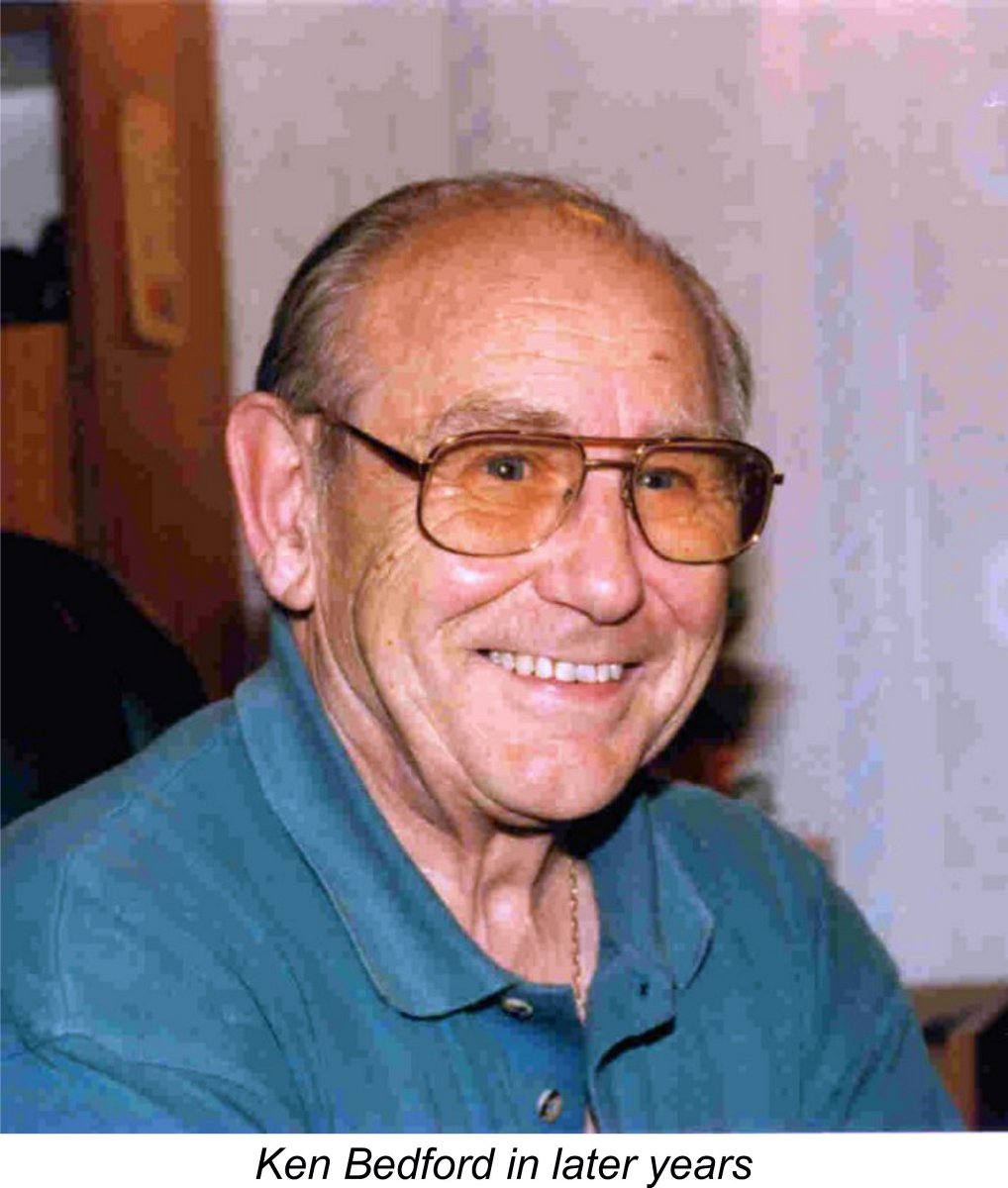
 In this article I’ll present a detailed historical review of one of the finest racing engines to emerge from a British manufacturer during the “classic” era. This is the ETA 29 glow-plug model from Watford in Hertfordshire, England. This outstanding British racing engine was designed by the late Ken Bedford (1924 – 2015). For completeness, I’ll also present a very brief historical summary of the companion ETA 19 model.
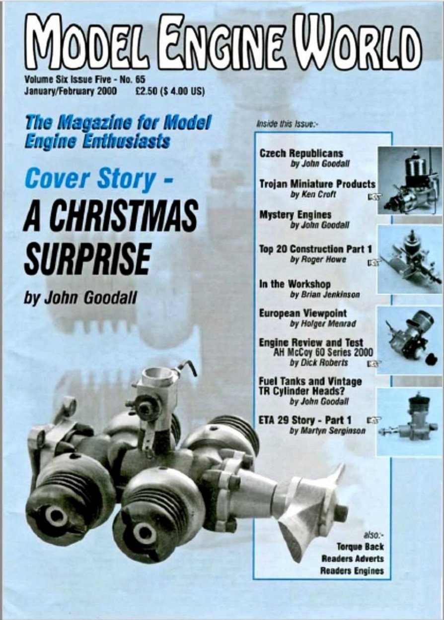
 Combined with Mrs. Bedford's wishes, this event quickly led to a decision by the couple to relocate back to England, taking their two young sons with them.
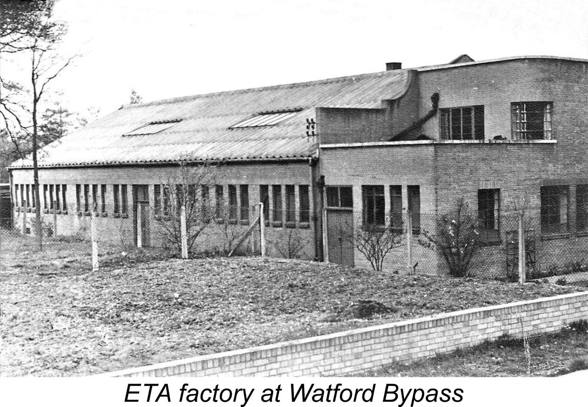 The company traded at this time under the name Bedford Products and Light Engineering Co. Ltd.
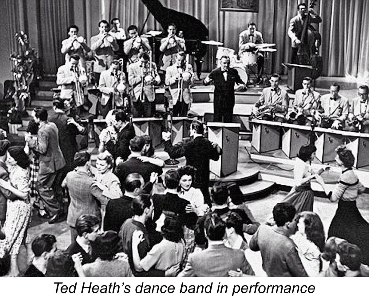
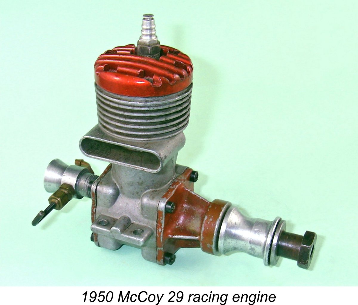 Ken Bedford somehow contrived to get a good look at an example of the McCoy 29 racing glow-plug model, which was a leading contender at this time (the Dooling 29 did not appear until mid 1949). Having done so, Ken commenced the development of a 5 cc racing engine which followed the design pattern of the McCoy fairly closely while incorporating a number of Ken’s own design features. The first model of this engine, known initially as the ETA 29 Model “A” for some long-forgotten reason, appeared in February of 1949. As events were to prove, it was the first in a long line of steadily-improving variants which were to remain in production right up to 1968.
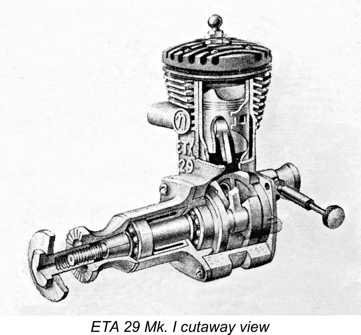 In basic engine design terms, the ETA 29 was a cross-flow loop-scavenged disc rear rotary valve (RRV) induction twin ball-race two-stroke design with a cast light alloy baffle piston. The attached cutaway view extracted from the September 1949 issue of "Aeromodeller" magazine shows many of its key features quite clearly.
 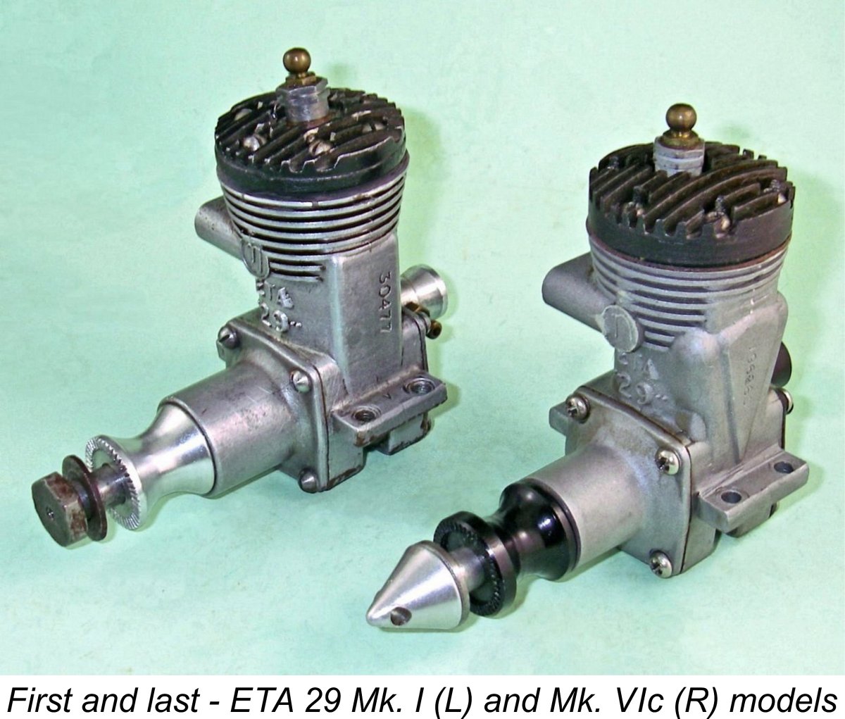 All models of the ETA 29 were to adhere to this basic formula throughout. The shape, placement, aperture numbers and style of the porting in the liner varied over the engine's lifetime, as did the conrod, piston baffle, disc valve and certain details of the crankcase casting around the top fin area and bypass flare. However, the basic functional design remained more or less unaltered throughout. In fact, the external appearance of the engine changed surprisingly little over the nineteen years during which it was in production.
 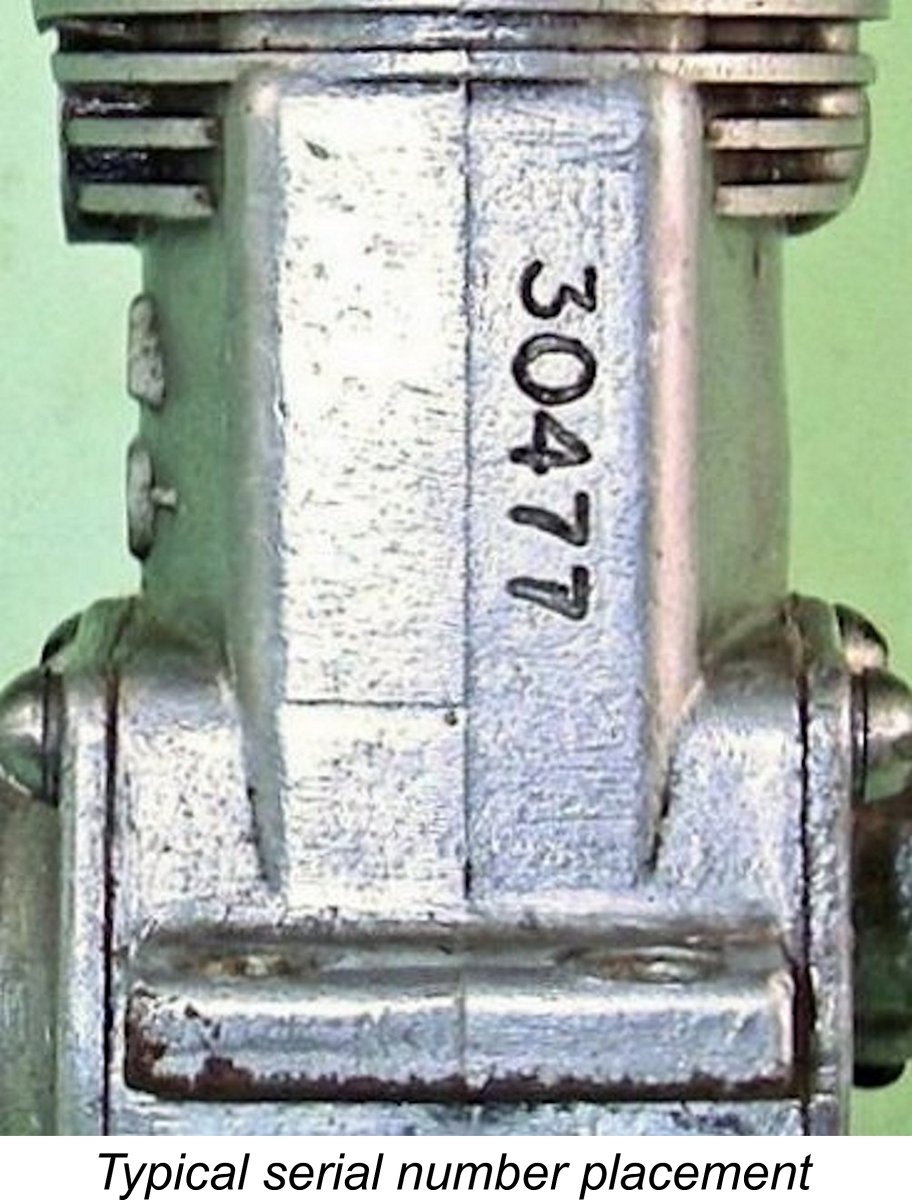 The serial numbering system applied to these engines offers considerable help in this area. However, it is by no means definitive. These numbers were applied to the outer surface of the bypass passage on the left side of the engine (looking forward in the direction of flight). As a result, the numbers go with the particular crankcase as opposed to the engine as a whole. The interchangeability of many components makes it necessary to confirm that all of the other components are consistent with the model indicated by the number before declaring a given example to be complete and original. Hybridization between models is actually quite common.
 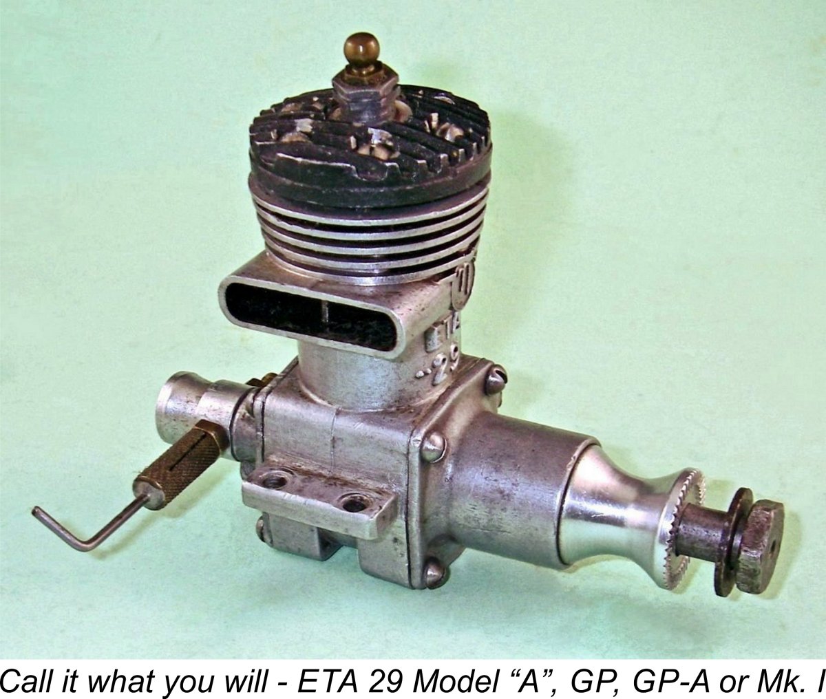 One important point that does require clarification before we begin is that of model designation. ETA themselves were strangely inconsistent in this regard. They initially designated the first model of the ETA 29 as the ETA 29 G.P. “A”. However, by mid 1949 this had been changed to the ETA “29” G.P. model (as written). A further change took place in early 1950, when the engine became identified as the ETA “29” GP-A (as written). To further confuse matter, the name reverted to the ETA “29” GP (minus the "A") in June of 1950 when the second variant of the engine was introduced. Just to really muddy the waters, Peter Chinn later mentioned that this second variant of the engine (which I have called the ETA 29 Mk. II) was referred to by the manufacturers as the “Series II” model, although this name did not appear in the advertising at any time.
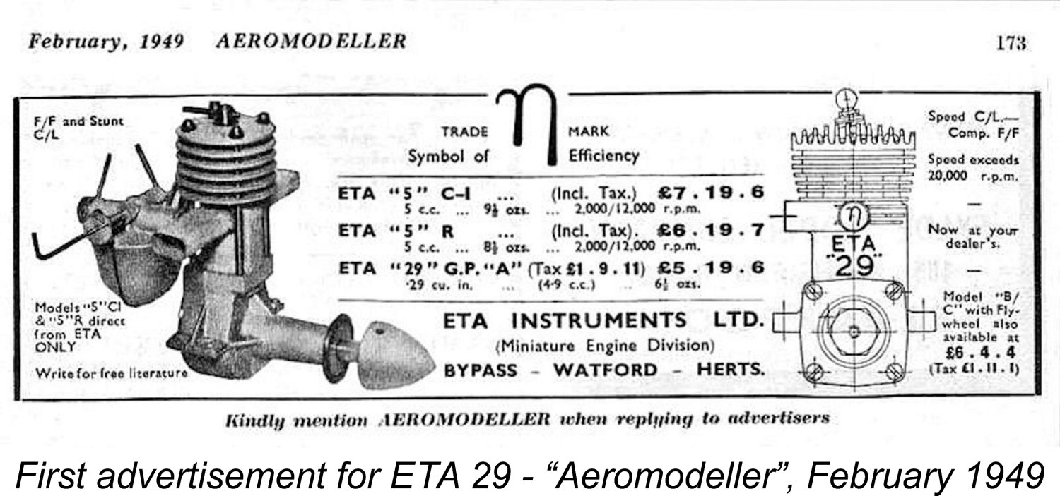 The ETA 29 Model G.P. “A” (as it was then called by its makers) reached the market in January 1949. For reasons which must forever remain obscure, the “A” designation was soon dropped and then re-instated, as noted earlier.
 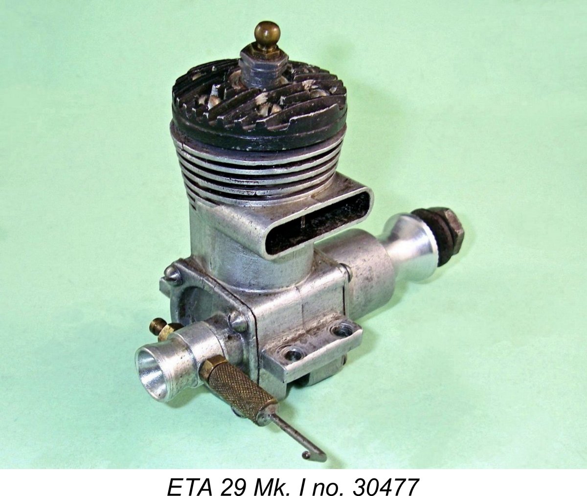 This model followed the specification presented earlier in every detail. In structural terms an unmodified example may be instantly recognized "across the room" by the fact that alone among the various ETA 29 models it had a separate plug-in venturi which was retained in the backplate by a set screw. The needle was carried in a large knurled split thimble with an internal 3 BA thread. This screwed onto an externally-threaded stub carrier.
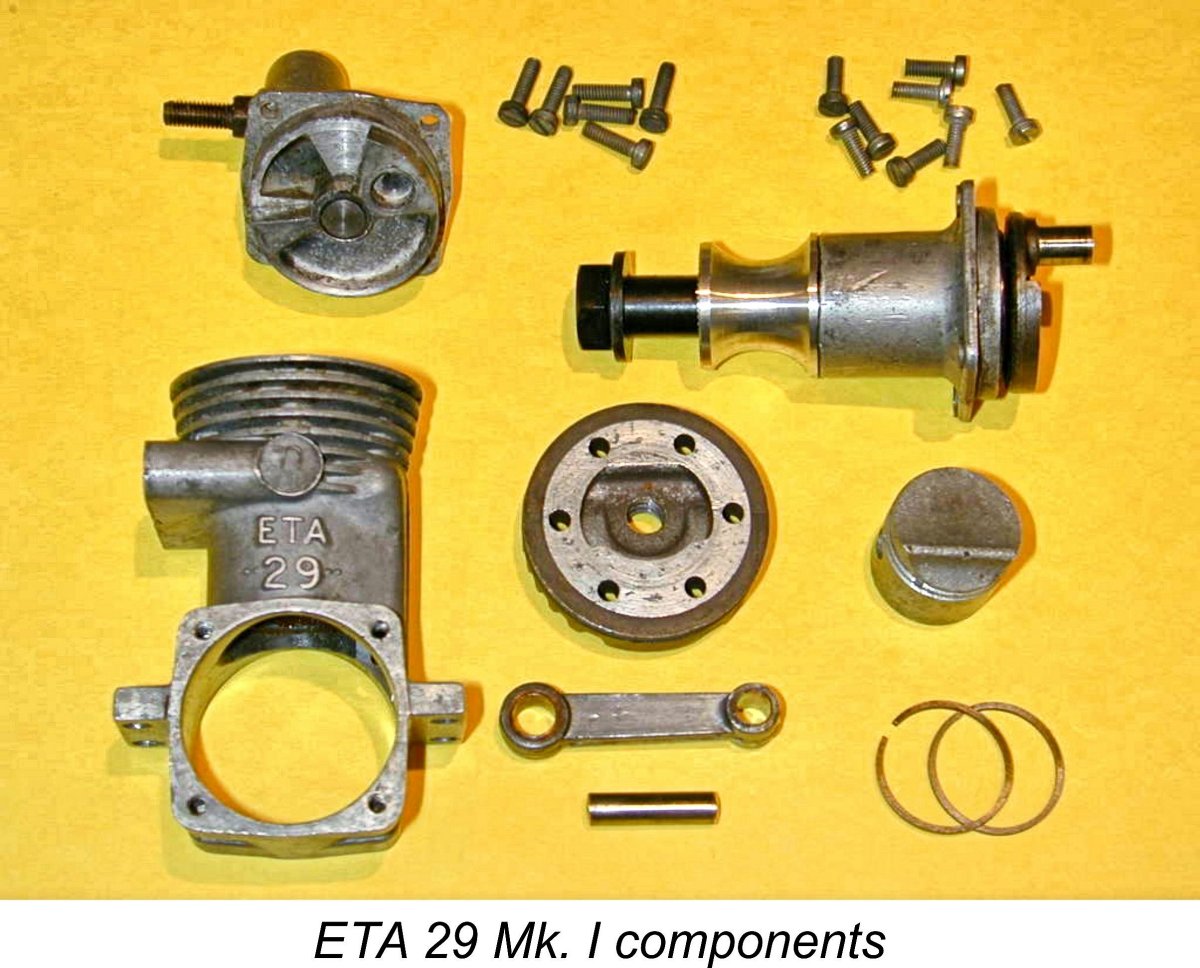 The rotary disc which controlled the induction cycle was of light alloy. This was soon found to be a quite unsuitable material for a high performance engine, wearing very rapidly in racing service. This being the case, it’s actually rather remarkable that it was to take ETA Instruments some 8 years to get around to rectifying this deficiency.
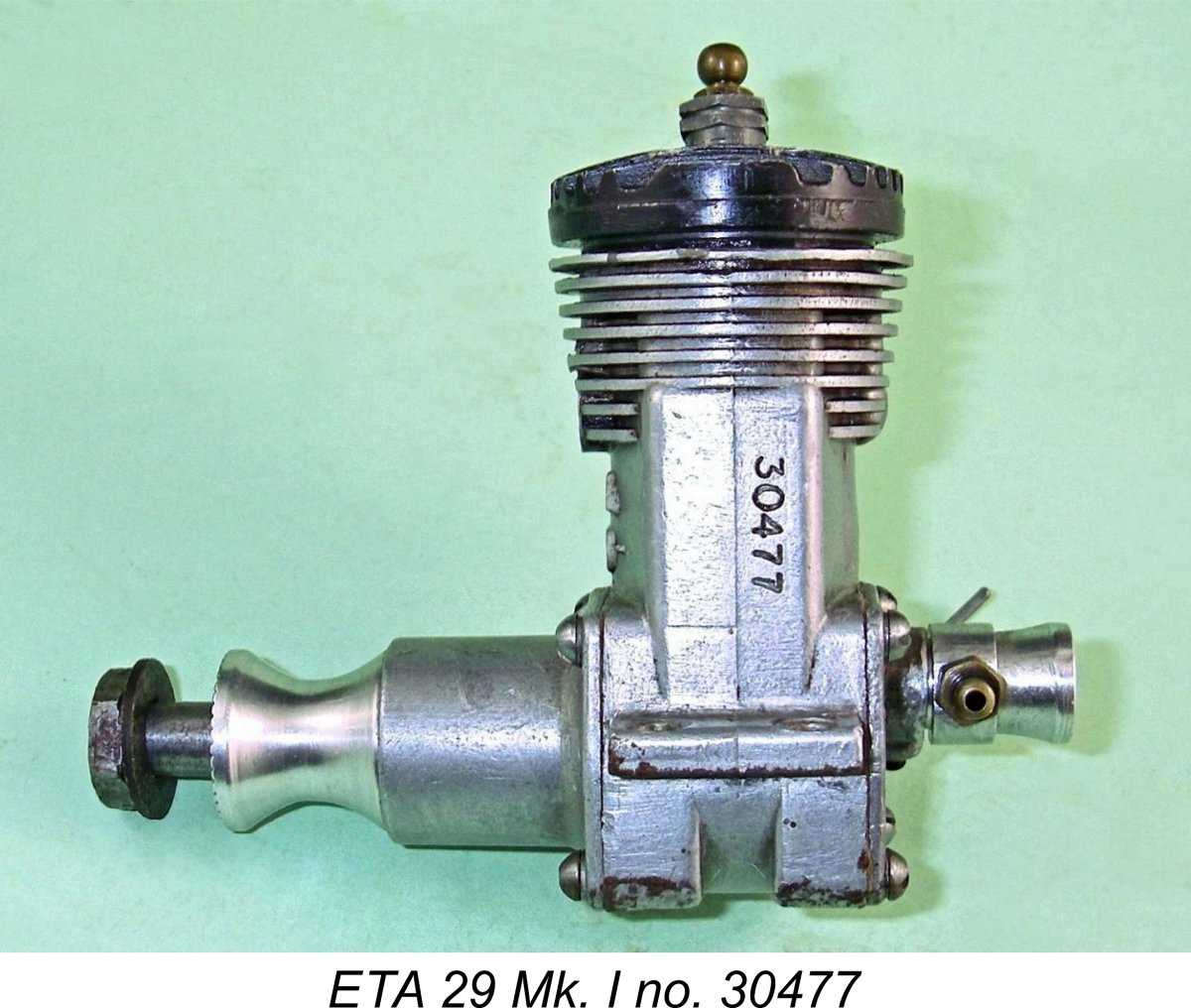 A revised rod design was soon developed by ETA also, proving to be somewhat more satisfactory than the original. This revised rod was slightly thicker and had bronze bushings at both ends instead of just the big end. However, the problems apparently persisted to some degree.
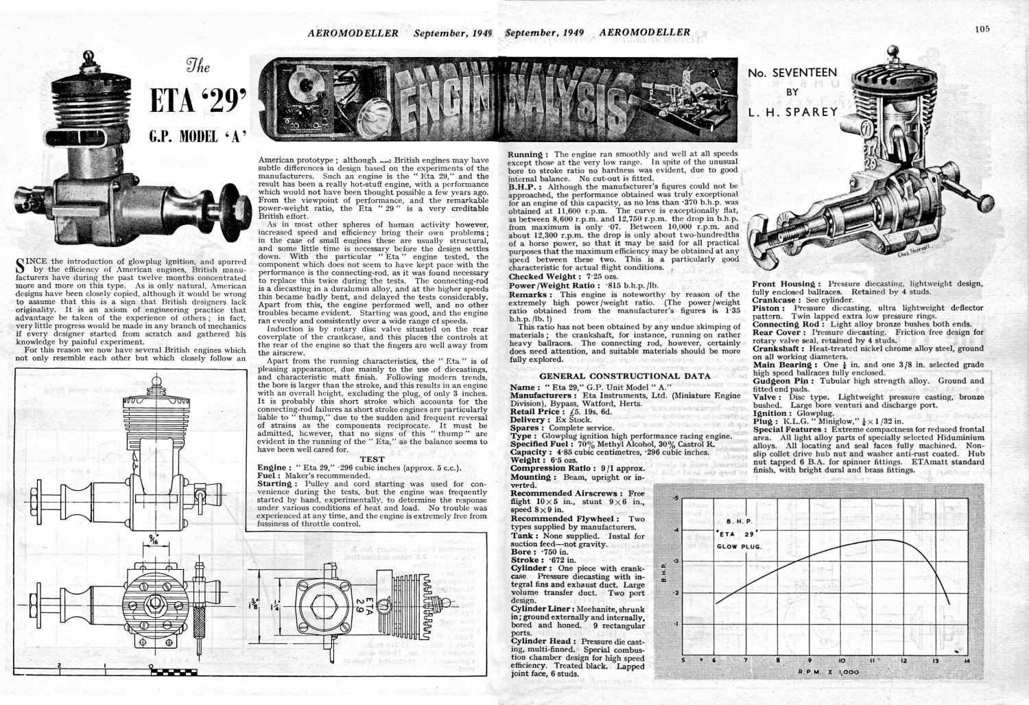
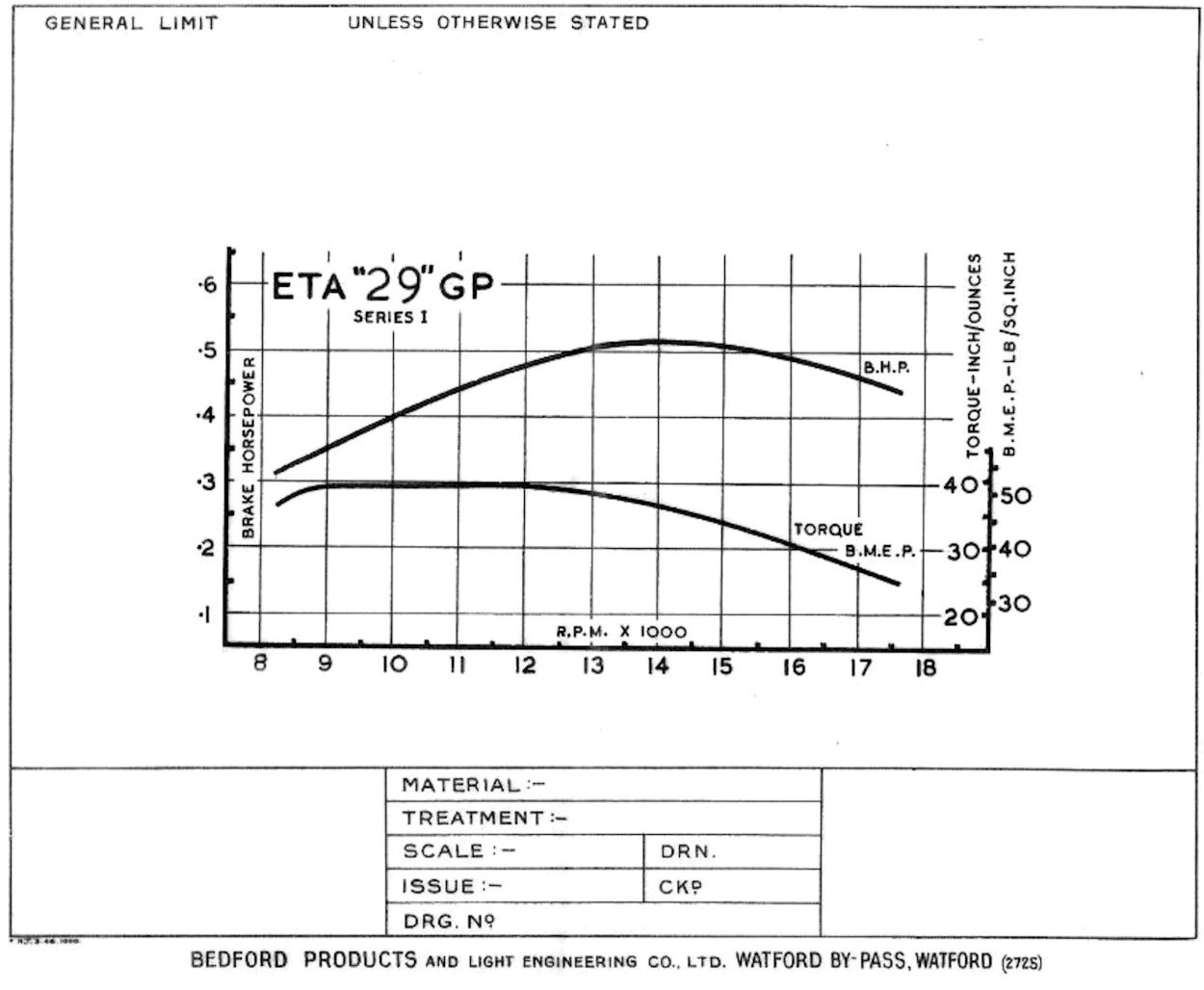 In fairness to Ken Bedford, it must be mentioned that his own tests on this model using his own dynamometer yielded far more positive results. Ken seems generally to have been extremely honest in making his promotional performance claims, and his published figure for the ETA 29 Mk. I was a far more flattering 0.54 BHP @ 13,250 rpm. His original test power curve has survived to be reproduced here thanks to the diligence of Miles Patience.
 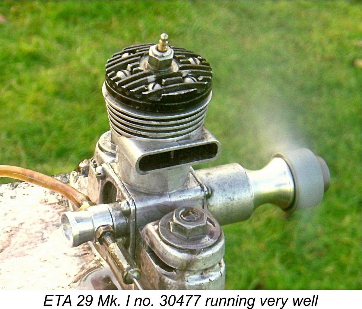 My opinion is supported by the findings of Peter Chinn’s unattributed test report on the ETA 29 Model “A” which appeared in the April 1950 issue of “Model Aircraft”. Chinn found a peak output of around 0.53 BHP @ 14,500 RPM, more or less precisely confirming Ken Bedford’s claims.
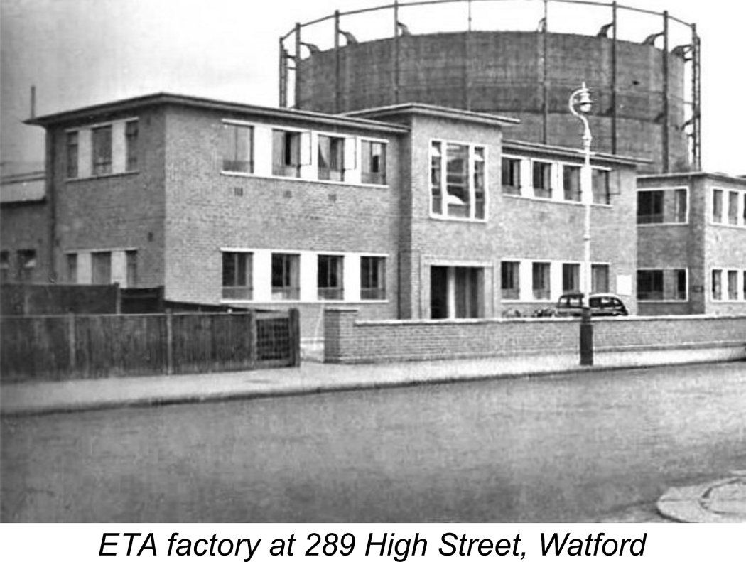
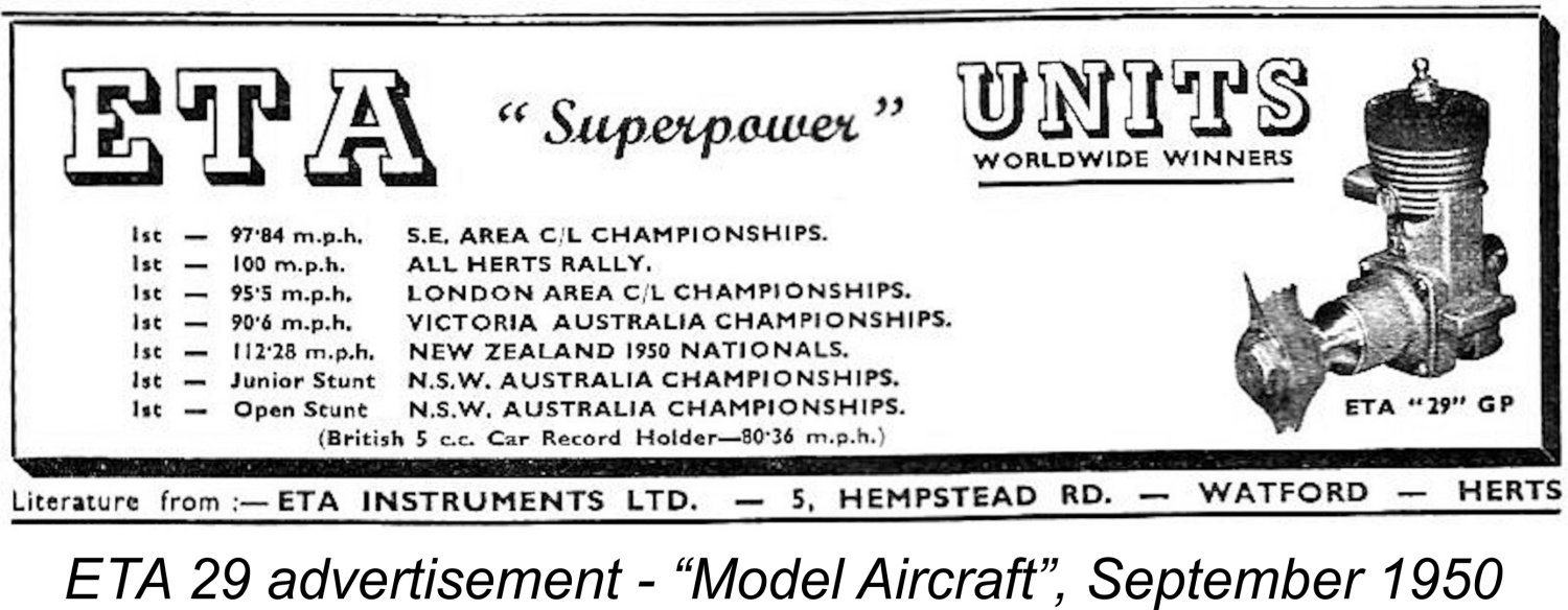 Interestingly enough, ETA themselves never advertised this variant under the Series II or Model G.P. "B" designations which one might expect. The engine continued to be advertised simply as the ETA 29 GP. There is internal evidence to show that ETA did indeed think of it as the Mk. II (or Series II) version of the engine as far as their own development sequence was concerned. However, it would appear that ETA did not consider the changes sufficient to warrant a re-designation of the engine, at least in an advertising context.
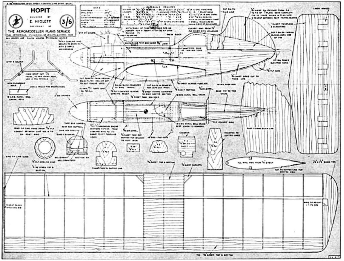
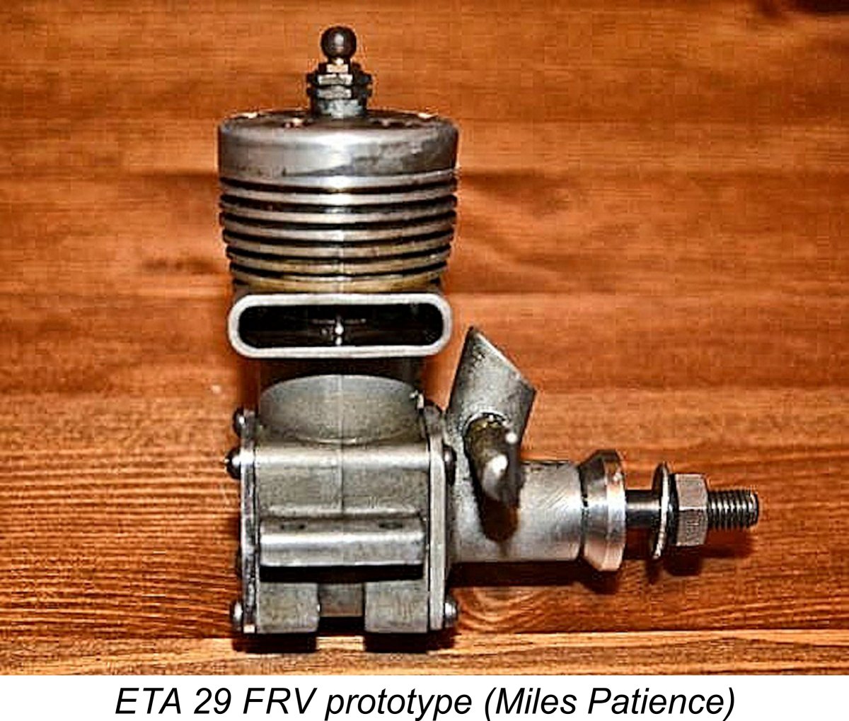
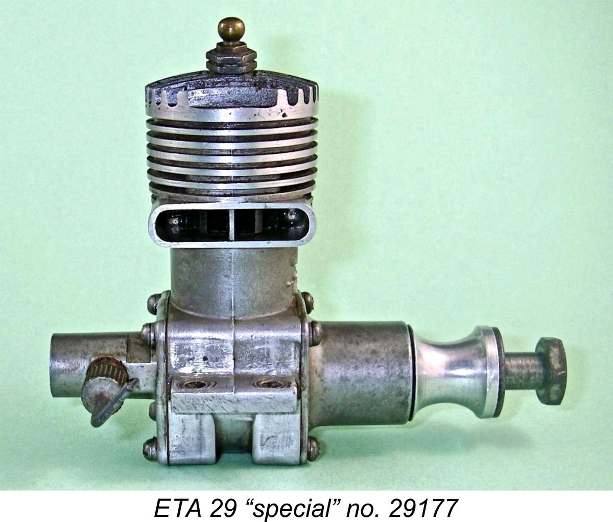
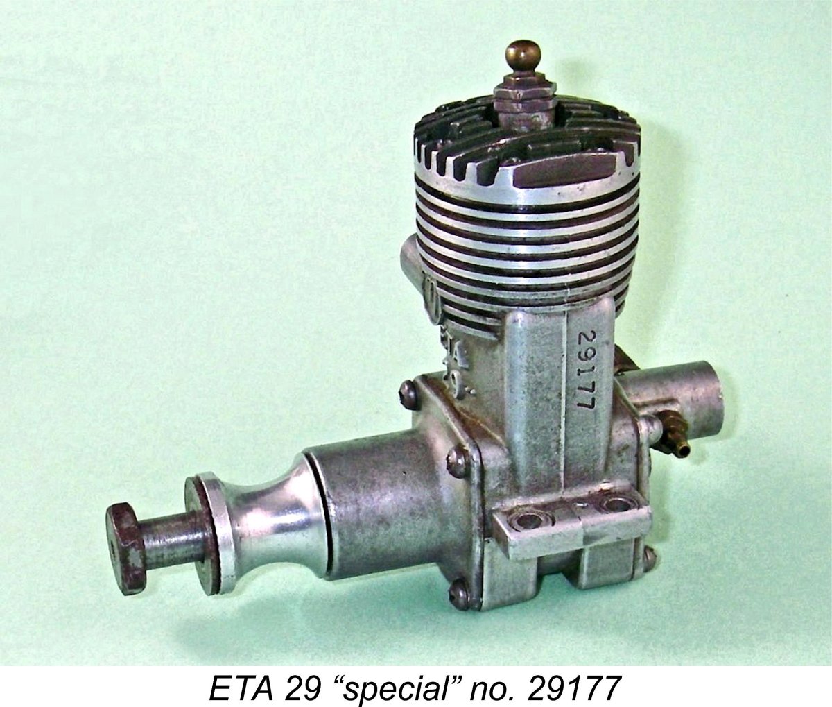
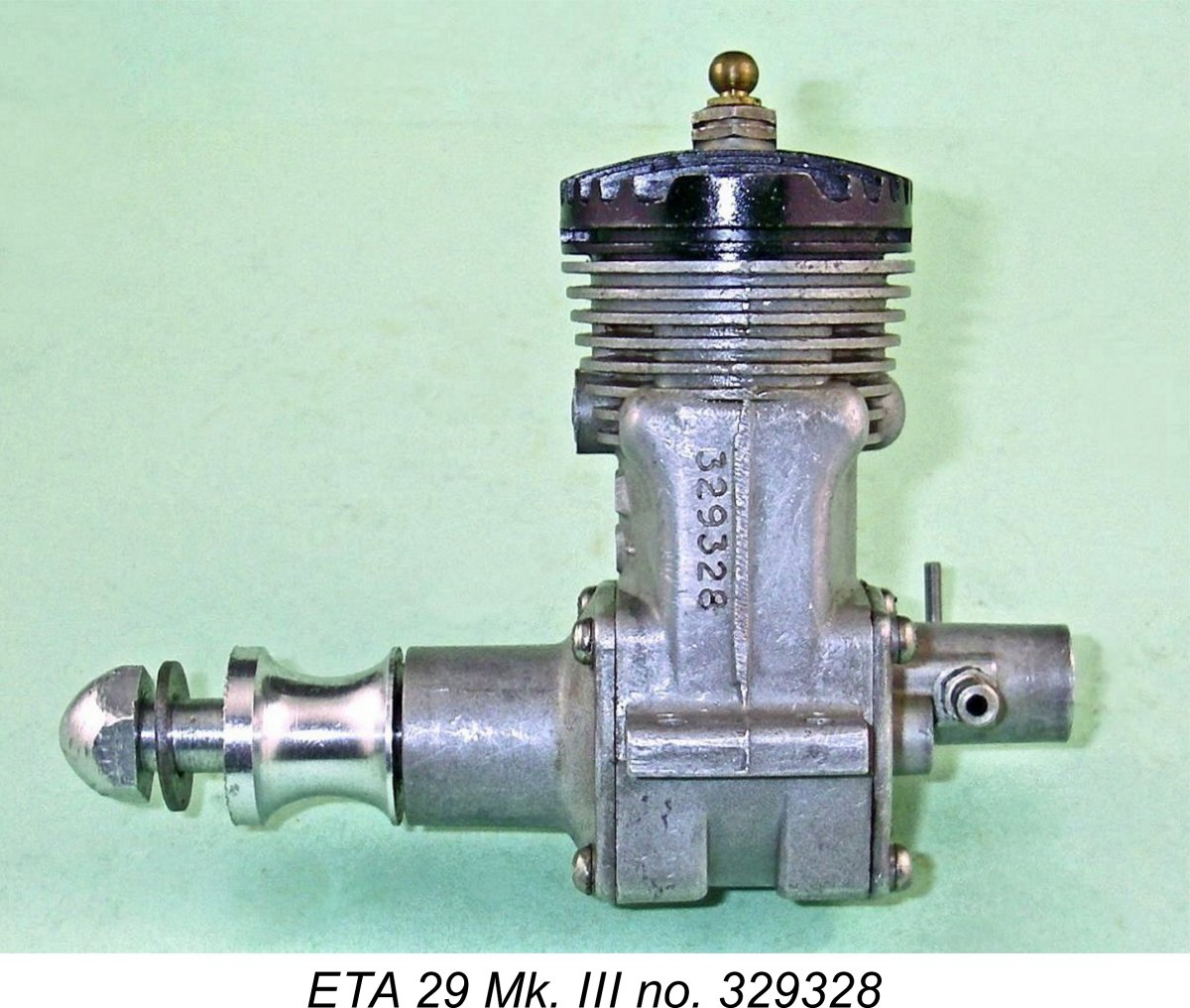 In November 1950 the Mk. III version of the ETA 29 appeared. The earliest examples differed little in external appearance from the MK. II. The new model retained the same head with angled glow-plug, the un-anodized one-piece backplate/venturi unit, the alloy rear disc and (initially at least) the large-diameter front bearing housing which had been used on the Mk. I and Mk. II engines.
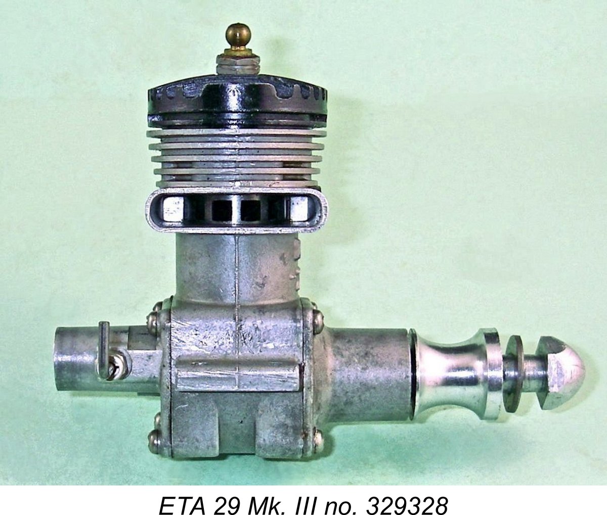
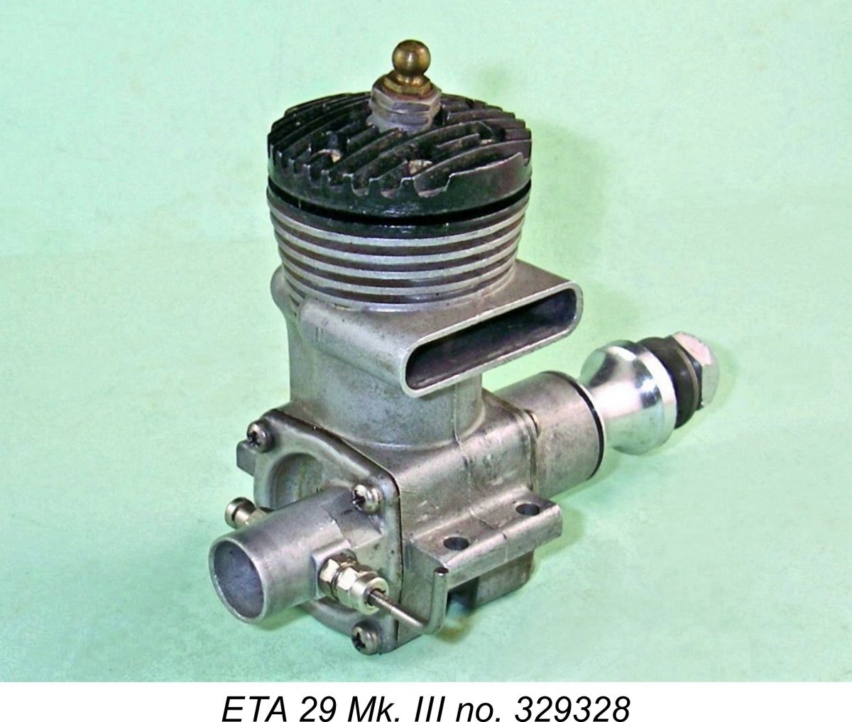
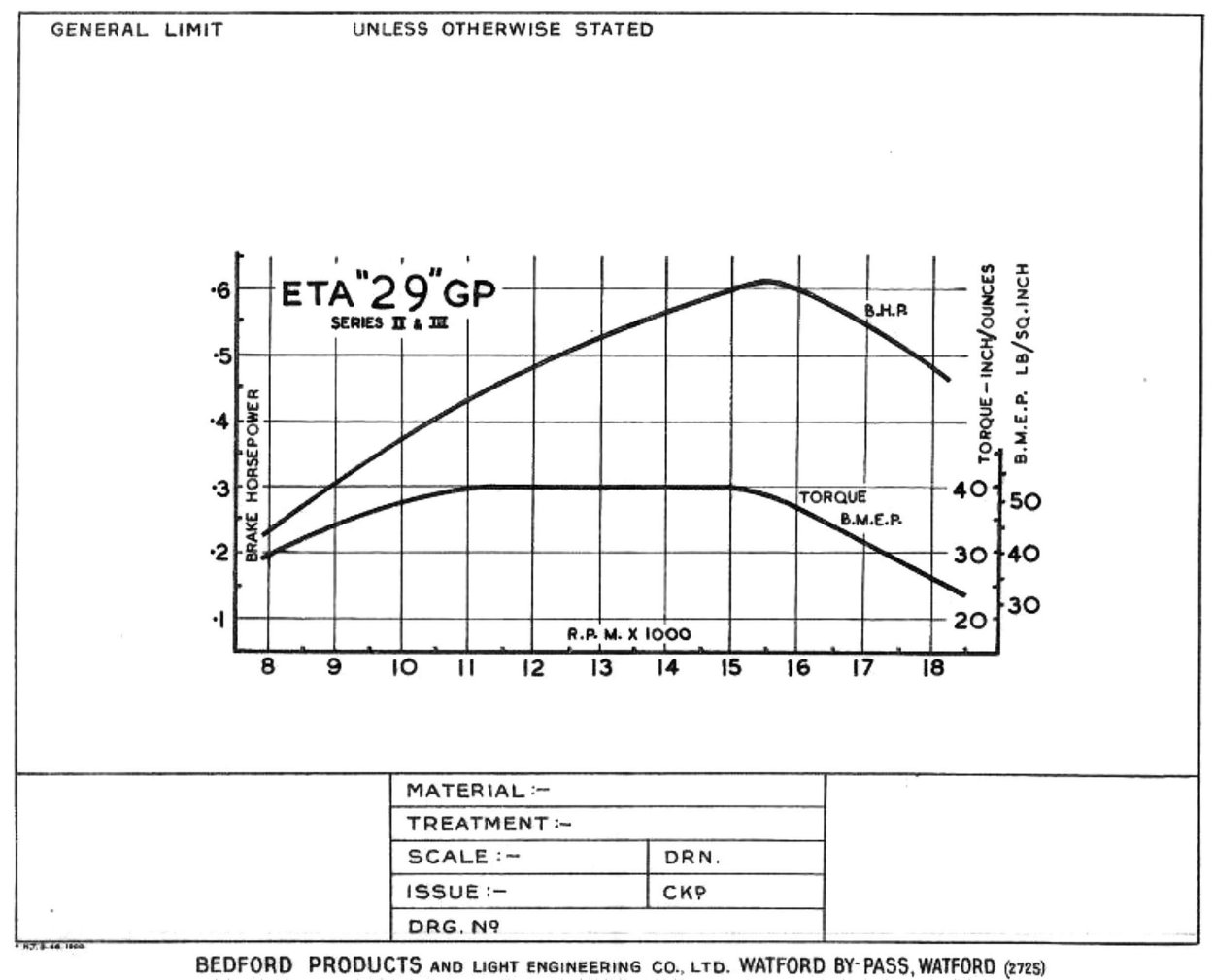
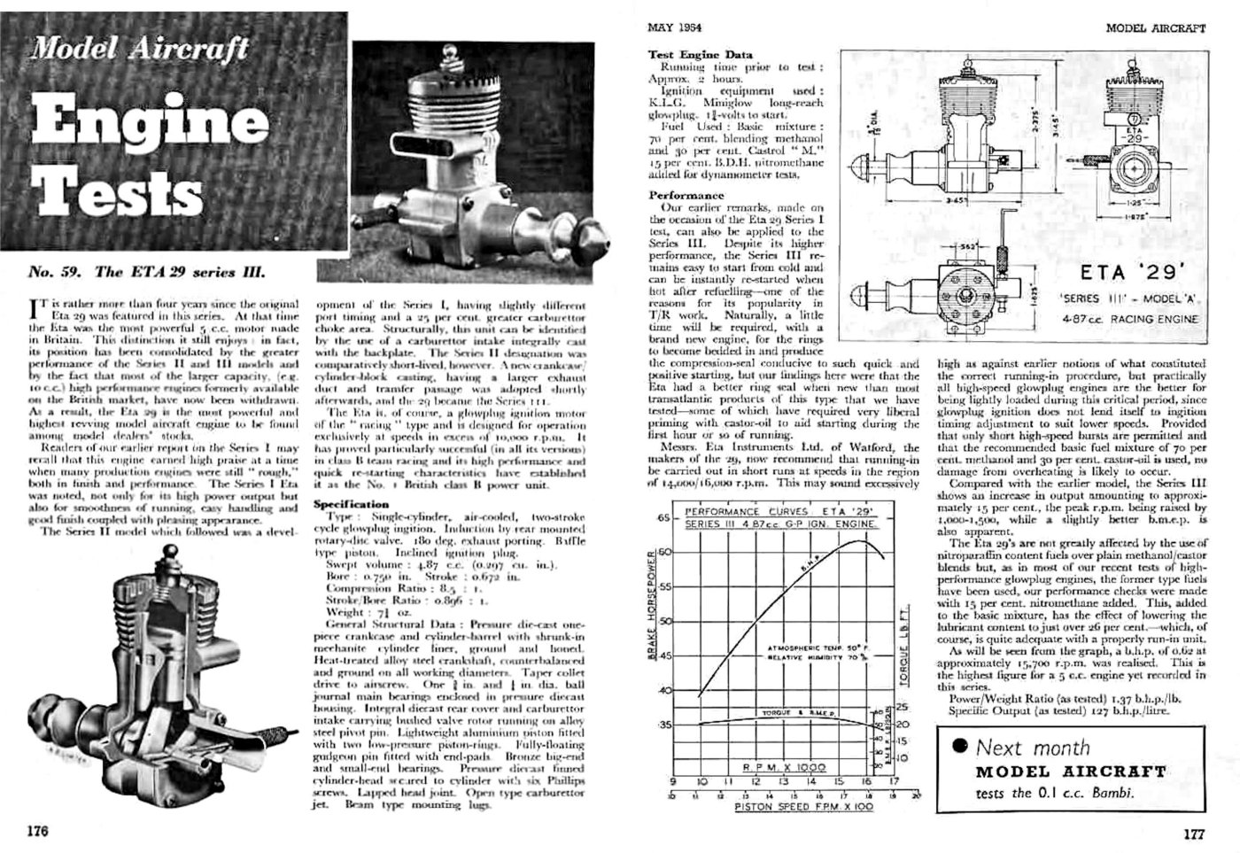 Chinn found a peak output of 0.620 BHP @ 15,700 RPM, which he characterized as being “the highest figure for a 5 cc engine yet recorded in this series”. This finding amply confirmed the ETA performance claim. Chinn was equally complimentary regarding the engine’s handling as well as its construction. He commented in particular upon the very good compression seal provided by the piston rings even before any running had been done to bed them in.
 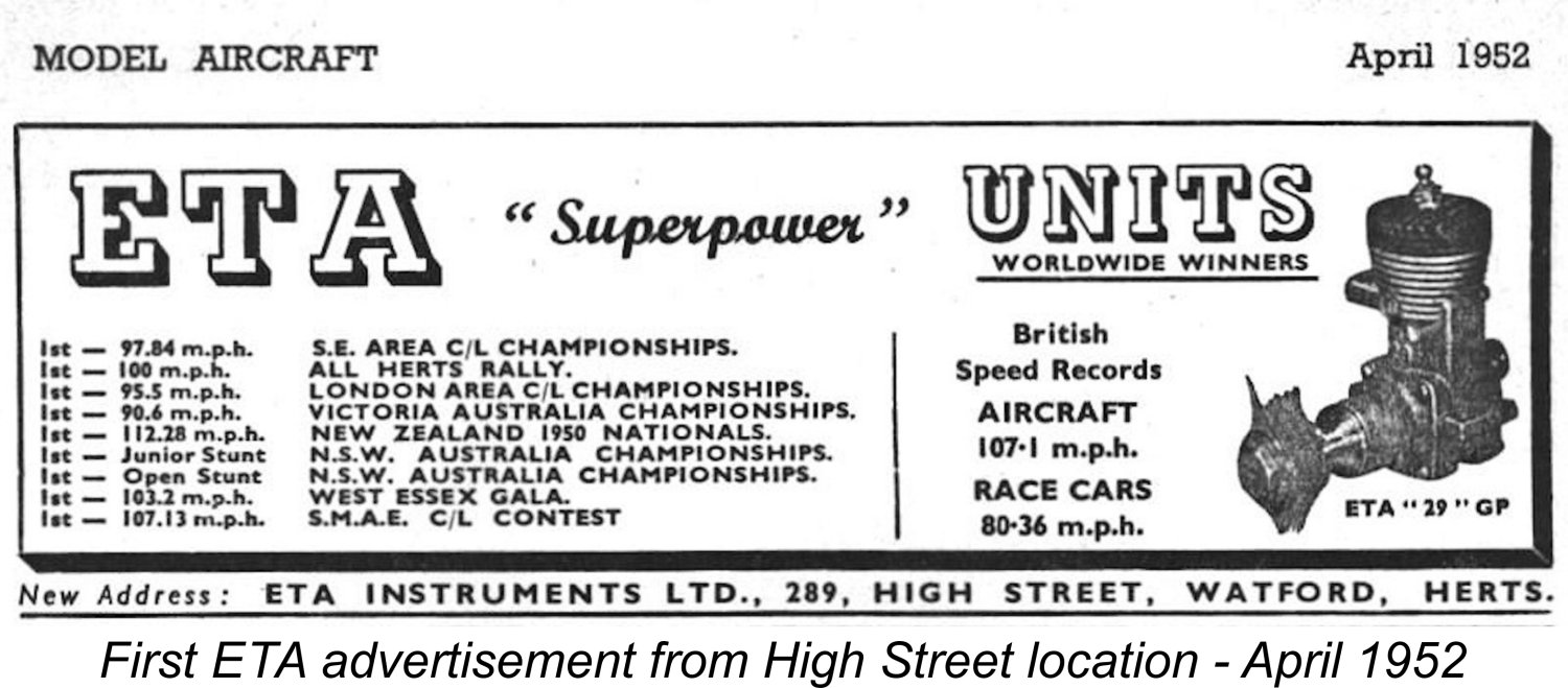 During early 1952 while the production of the ETA 29 Mk. III was in full swing, the company finally consolidated both its business and manufacturing activities at 289 High Street in Watford. Based on the addresses given in the company’s advertising, this change was made in around February 1952. All subsequent examples of the ETA 29 right up to 1968 were produced at this location. No more was heard of the Hempstead Road location - perhaps the family had sold the garage there.
 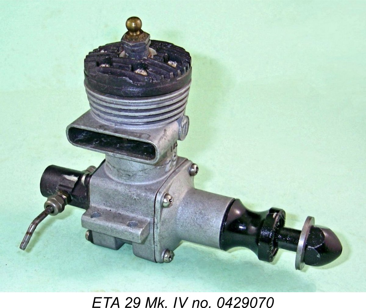 In August of 1956 a further revised model of the ETA 29 appeared in the shape of the Mk. IV version of the engine, which sold for a slightly increased price of £7 6s 4d (£7.32). Externally, this new model featured black anodizing on the backplate, aluminium alloy sleeve prop nut and prop driver to match the similar finish on the cylinder head. Otherwise, it looked more or less identical to its predecessor.
 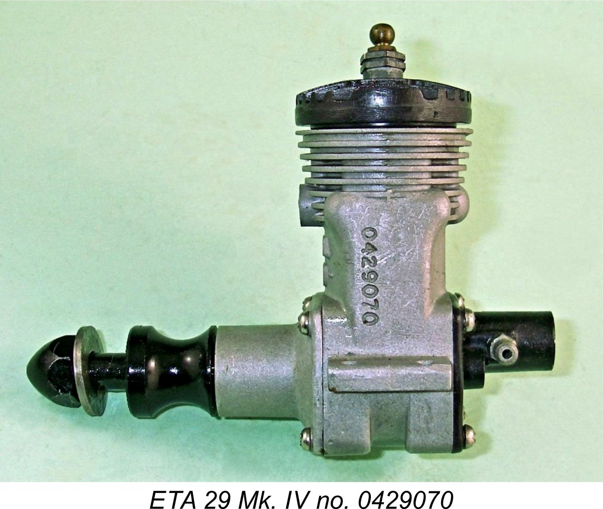 Internally, the engine was provided with a ported piston skirt on the bypass side with matching cylinder ports to assist the transfer process, very much along the lines of the system employed in the
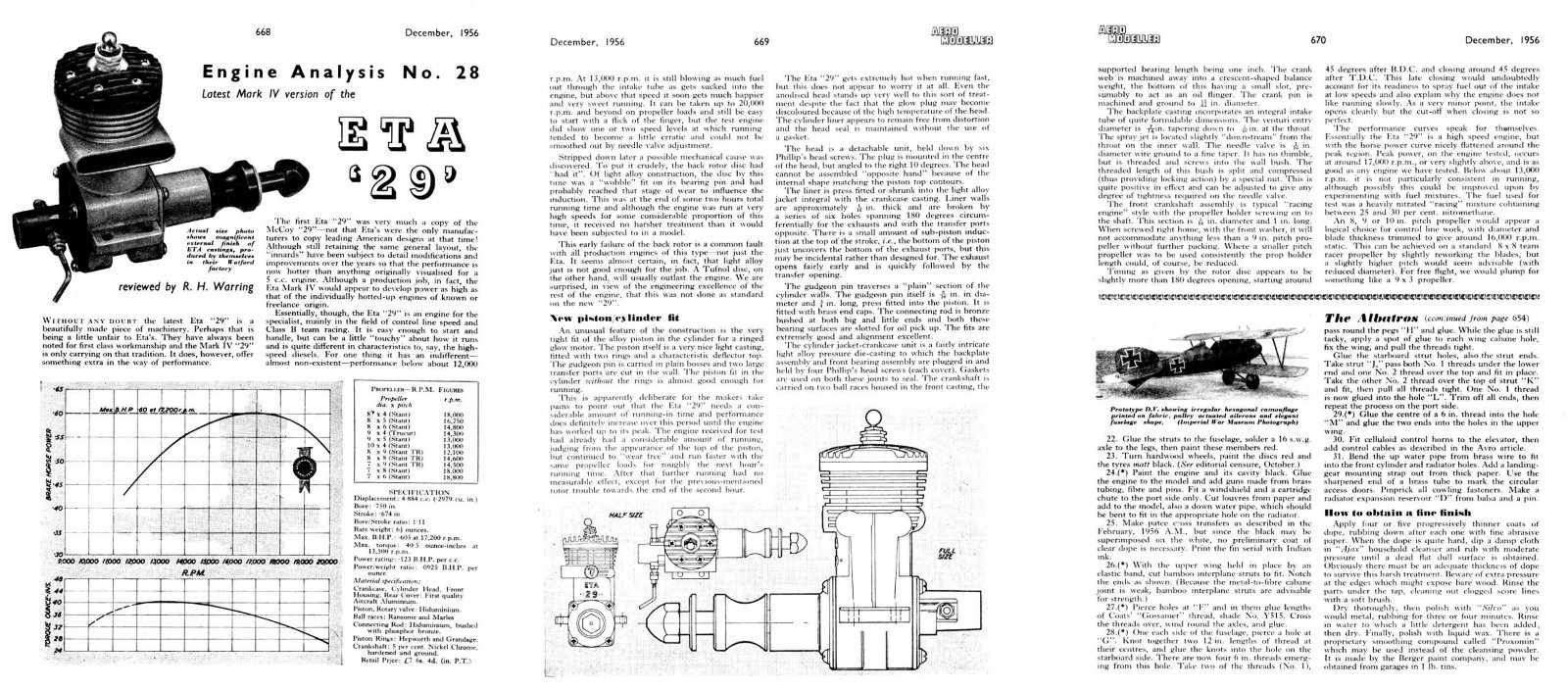
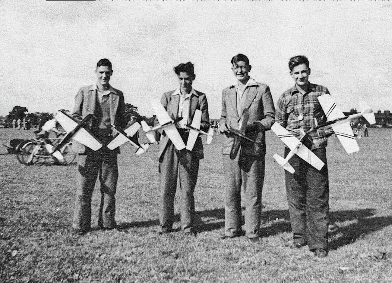 Ray Tuthill and Don Walker started out in team racing independently in 1952 as members of the Enfield District Model Aero Club, frequently racing against each other in separate teams at that stage. The attached image was taken at the All-Herts Rally held in 1953 at the Handley Page factory test airfield at Radlett in Hertfordshire. It shows Ray on the left with his Class “A” model (powered by an
 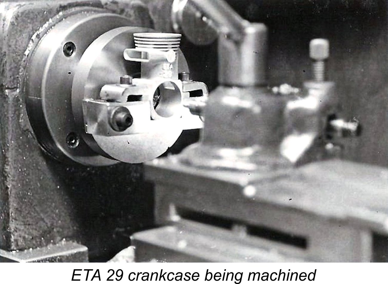 Not being one to rest on his laurels, Ray then proceeded to build up his own example of the ETA from scratch. This engine incorporated the previously-mentioned early ETA Mk. I crankcase bearing the serial number 309. This case was re-machined to ensure absolute geometric accuracy and was fitted with an ETA front end assembly which had been carefully fettled. A modified ETA back end assembly was also used, albeit with Ray’s own replacement disc valve. The cylinder liner, cylinder head, piston, con-rod, spraybar and needle were all of Ray’s own making, although the excellent standard ETA piston rings were retained. These rings were actually made by Wellworthy under contract to ETA, as noted earlier.
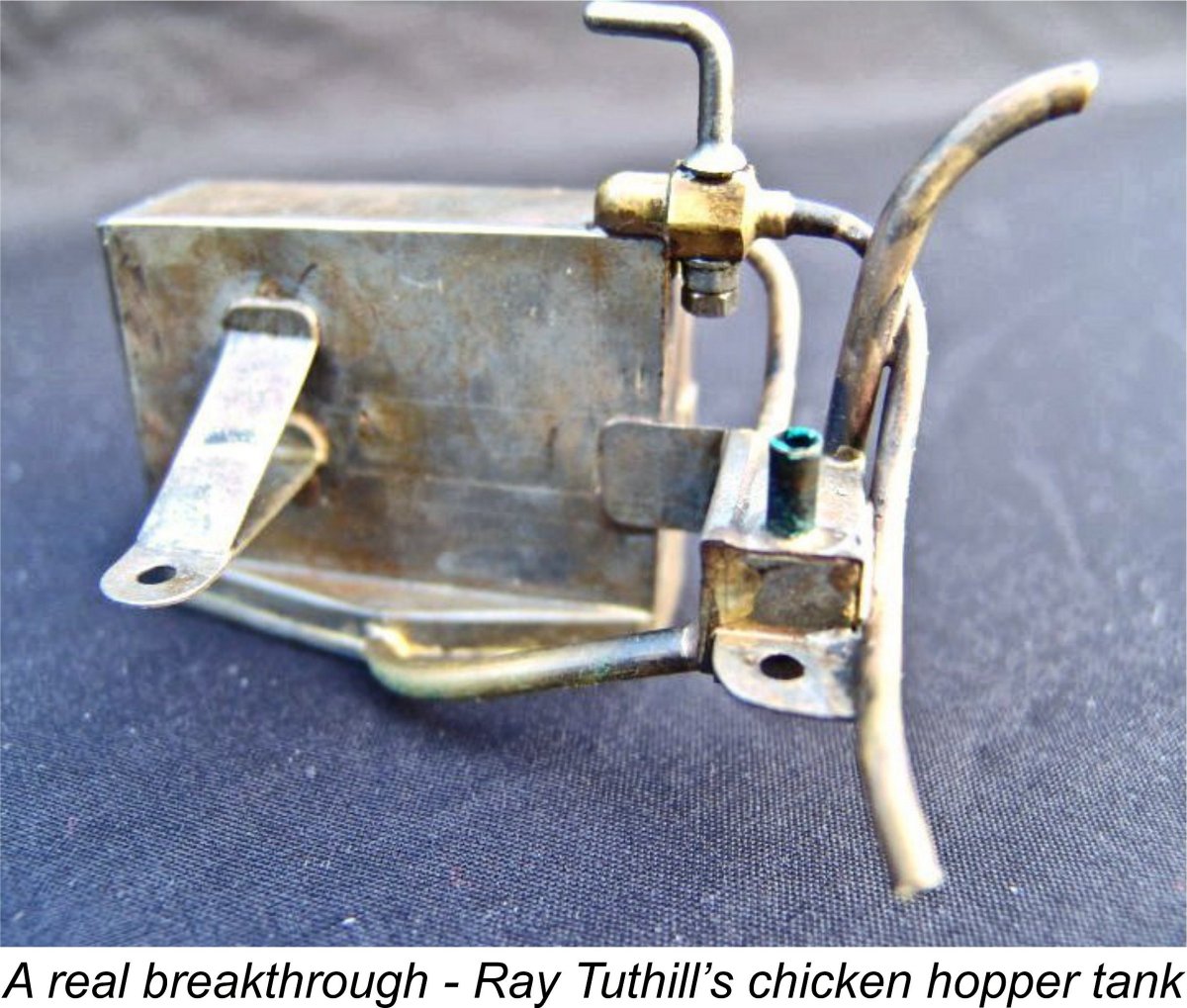
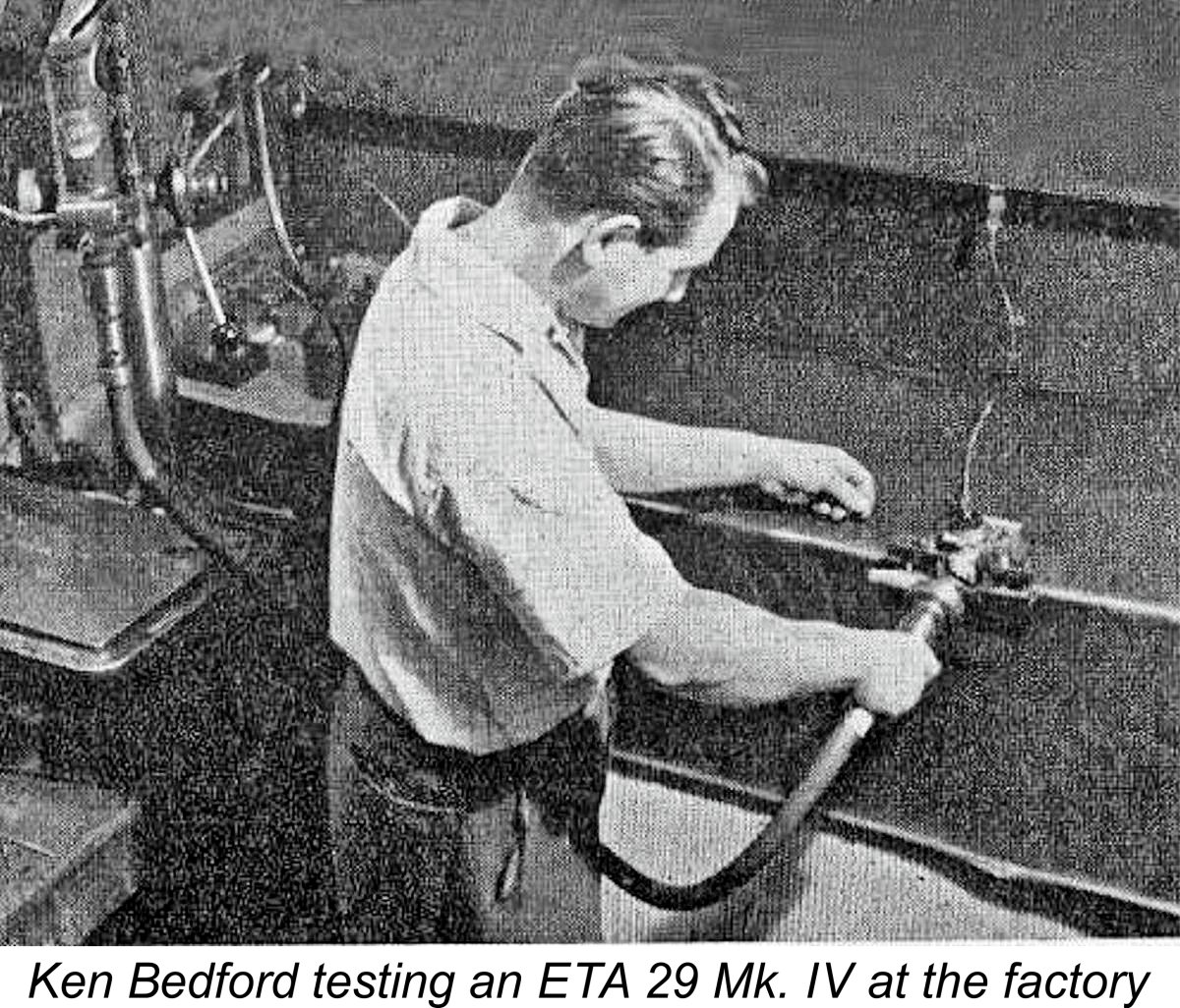 It was the team’s remarkable run of successes with this engine that brought them to the attention of Ken Bedford. He introduced himself to Ray and Don, thus beginning a long friendship. He was extremely interested to learn what Ray had done with the basic ETA design, since it was performing better than Ken’s production models at the time. Ray in turn was naturally very keen to see what the power curve looked like, so the team took Ray’s engine to ETA’s works at Watford and put it on Ken’s dynamometer, where it peaked with an output of 0.746 BHP at 17,600 rpm.
 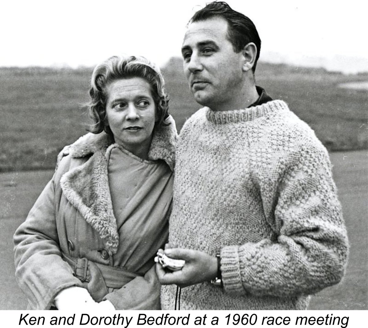 Ken was of course suitably impressed, to the point that he invited Ray and Don to become in effect the “ETA works team”. He immediately began to apply some of their modifications to the production engines, resulting in due course in the appearance of the ETA 29 Mk. V model which will be described in the following section of this article.
 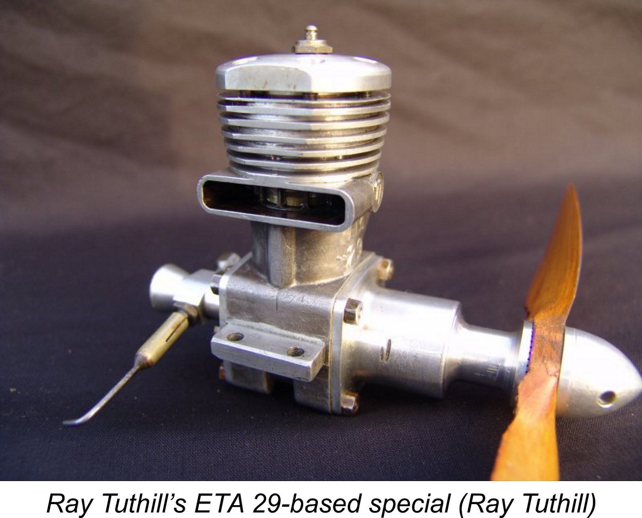 Using one of the unnumbered cases scrounged from Ken Bedford’s scrap bin, Ray built a second engine along the lines of his first self-constructed effort. This one used an ETA crankcase, crankshaft, piston rings and ball races, but everything else was made by Ray himself. Although somewhat more robust, in its essentials it was identical to the first engine that Ray had built, including the extension to the crankcase and the associated modified cylinder head design to minimise any malign influence on the liner geometry when tightening the cylinder head screws.
 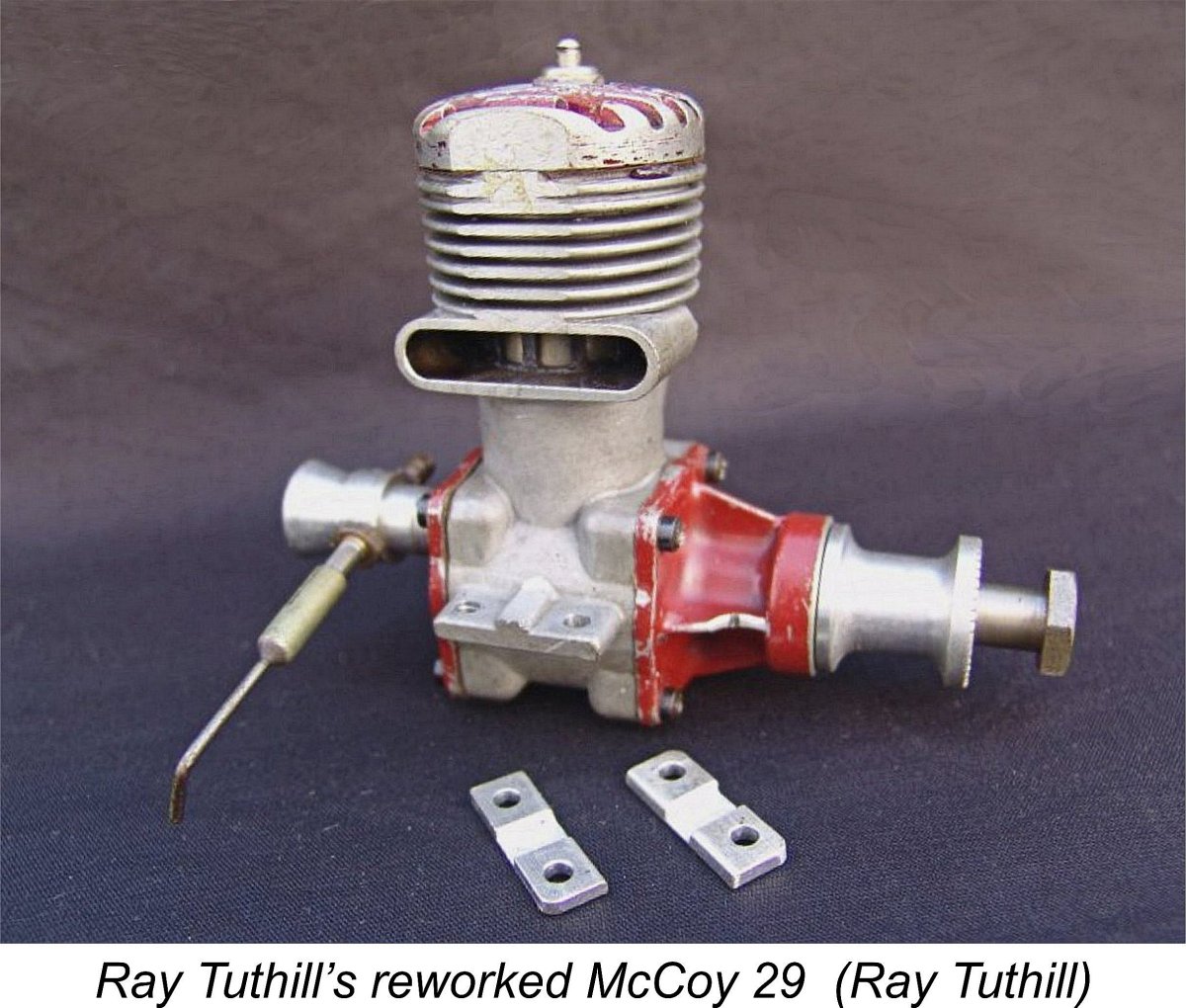 While Ray had been hard at work on these projects, Ken Bedford had not been idle. He had taken note of Ray’s efforts and had incorporated many of Ray’s ideas into the design and manufacture of his own production ETA 29 models. The initial result was the June 1957 appearance of the ETA 29 Mk. V, which was followed in September 1958 by the further improved ETA 29 Mk. VI. Both of these models will be discussed in detail below.
 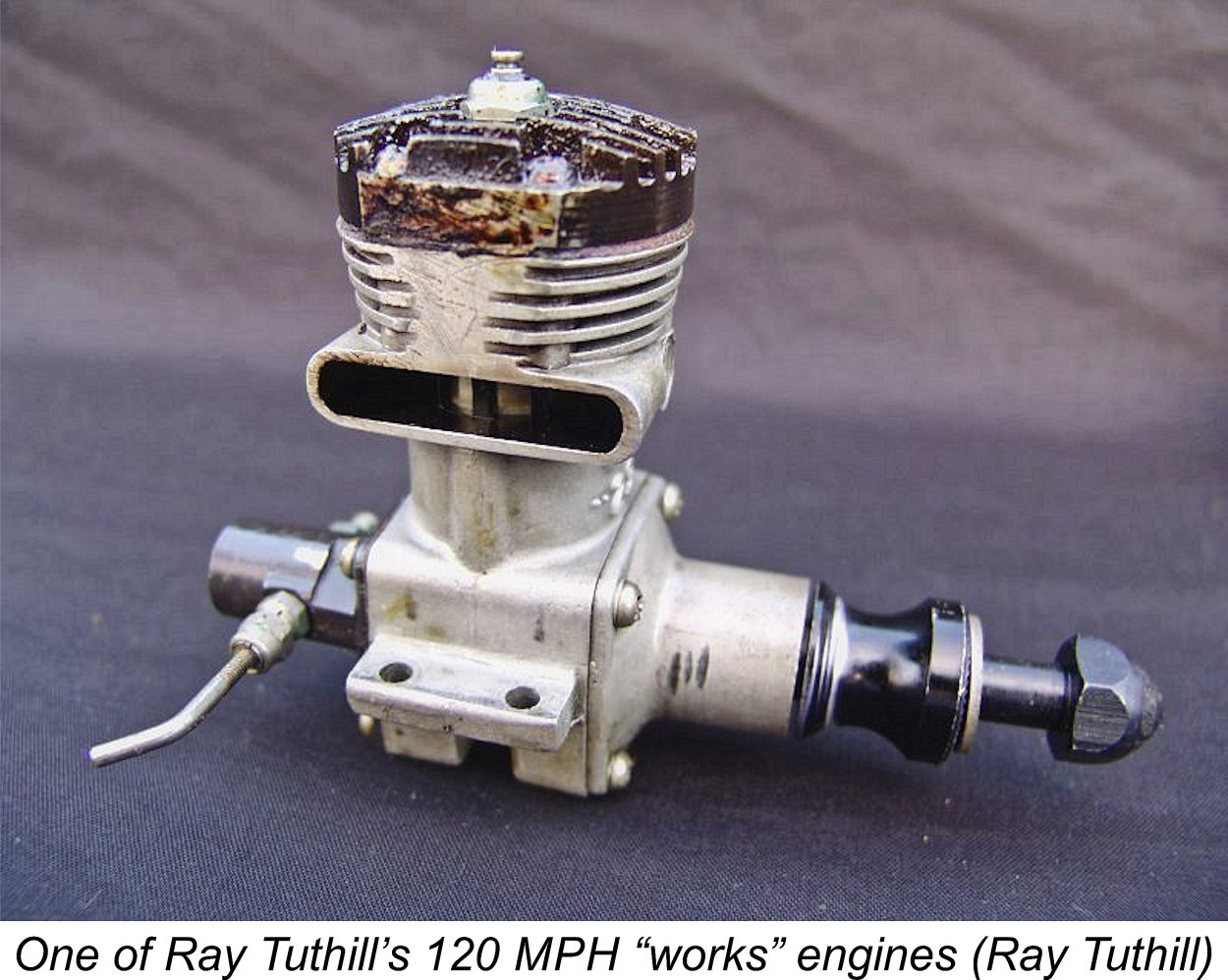 From the late 1950s through to 1961, Ray and Don test-flew and raced a number of Ken Bedford’s factory engines for him. When Ken got a particularly good example off his production line he would ask his “works team” to test-fly and if possible race it. As time went by, Ken refined both the engine’s design and his production and assembly techniques. Consequently, the engines progressively became more powerful. They also exhibited much improved consistency, to the point that the majority of the production ETA’s were remarkably close to the best!
 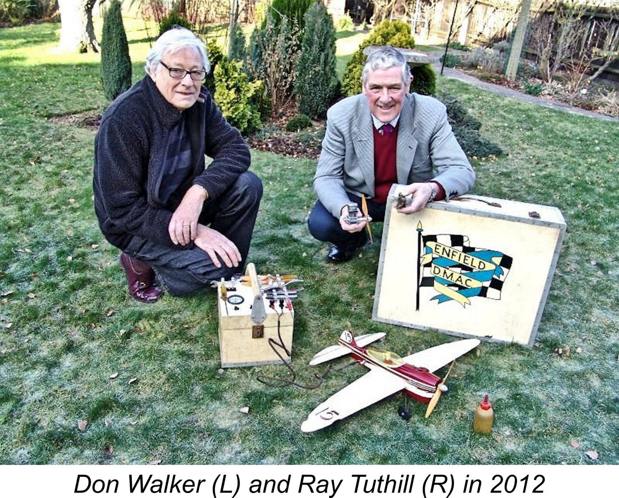 Ray and Don continued to compete in Class “B” as a team until 1962, in which year a combination of careers, marriages, house purchases and families intervened and brought the Class “B” team racing activities of Don and Ray to an end. However, they had made an indelible mark upon the field of competition control-line aeromodelling. I myself recall seeing them race at several meetings which I attended as a teenager, and being totally mesmerized by the howl of those fabulous ETA 29’s eating up the laps. The team had also made an immense contribution to the development of the ETA 29 into its fully-developed guise.
 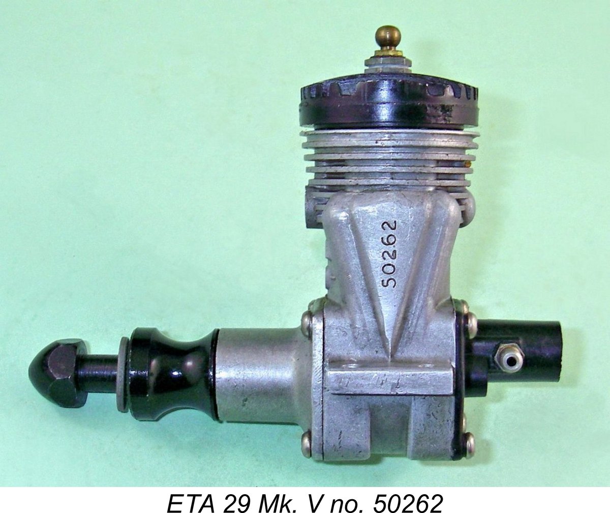 The Mk. V version of the ETA 29 which appeared in June 1957 is significant in that it was with this model that Ken Bedford finally replaced the inadequate alloy disc valve with a far more durable component made of Tufnol. This disc was mounted on a left-hand threaded rotor pin which required the use of a special ETA tool for removal.
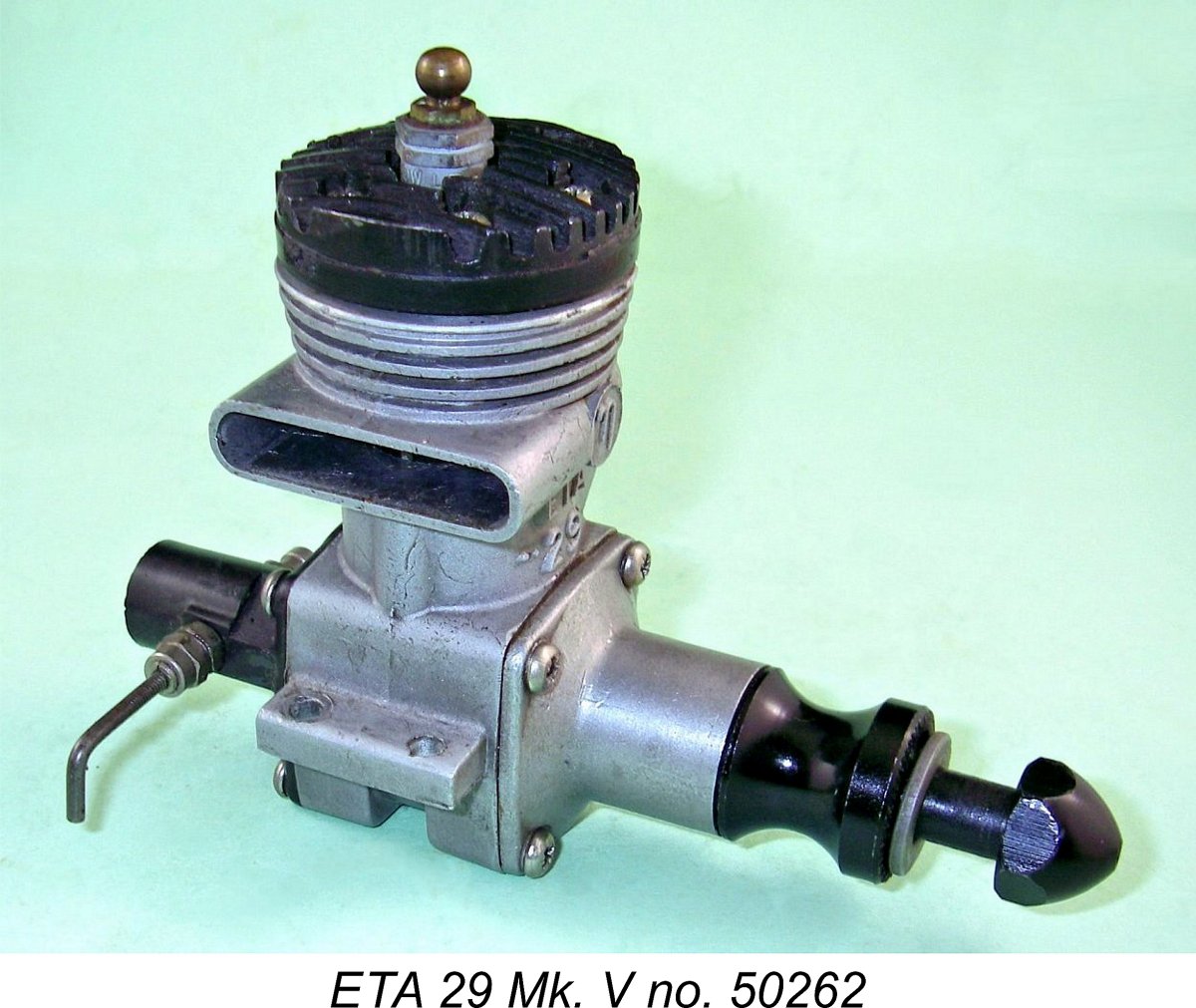 The engine used a revised flat-topped baffle piston without skirt ports - those seen on the previous model turned out to be a relatively short-lived experiment. A
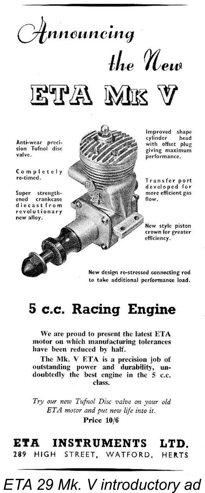
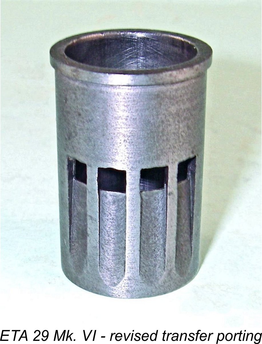 The next variant of the engine was the ETA 29 Mk. VI, which was first announced in September 1958. The selling price of the engine remained unchanged at £7 6s 4d (£7.32).
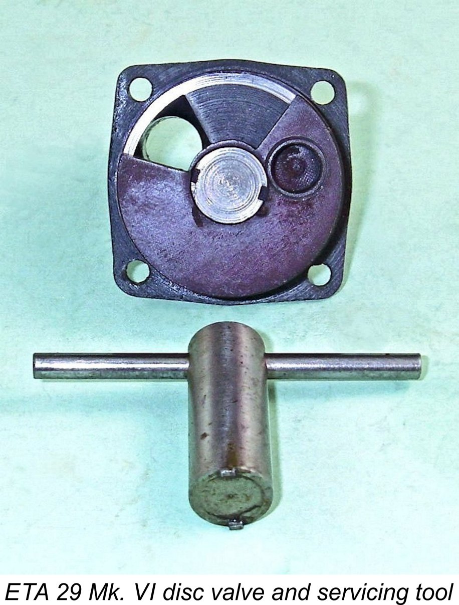
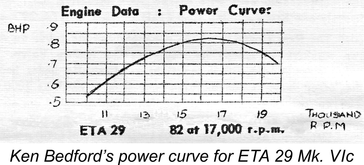
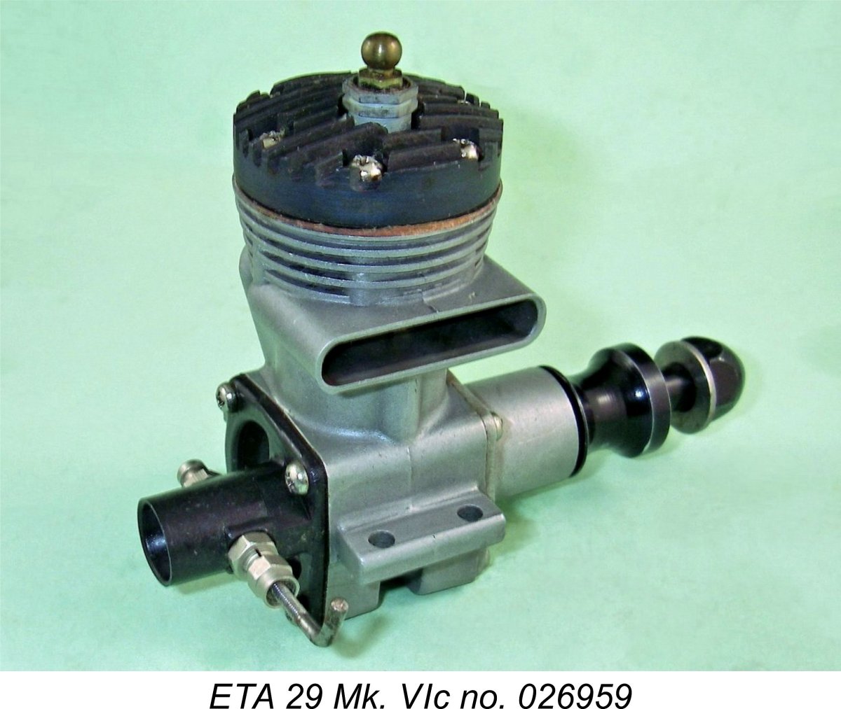 In late 1959 the factory began to refer to the ETA 29 Mk. VI as the Mk. VIc. This change was reflected both on the engine boxes and literature as well as in the company’s advertising. As of April 1960 the selling price of the engine (including taxes) had actually fallen very slightly to £7 1s 11d (£7.10).
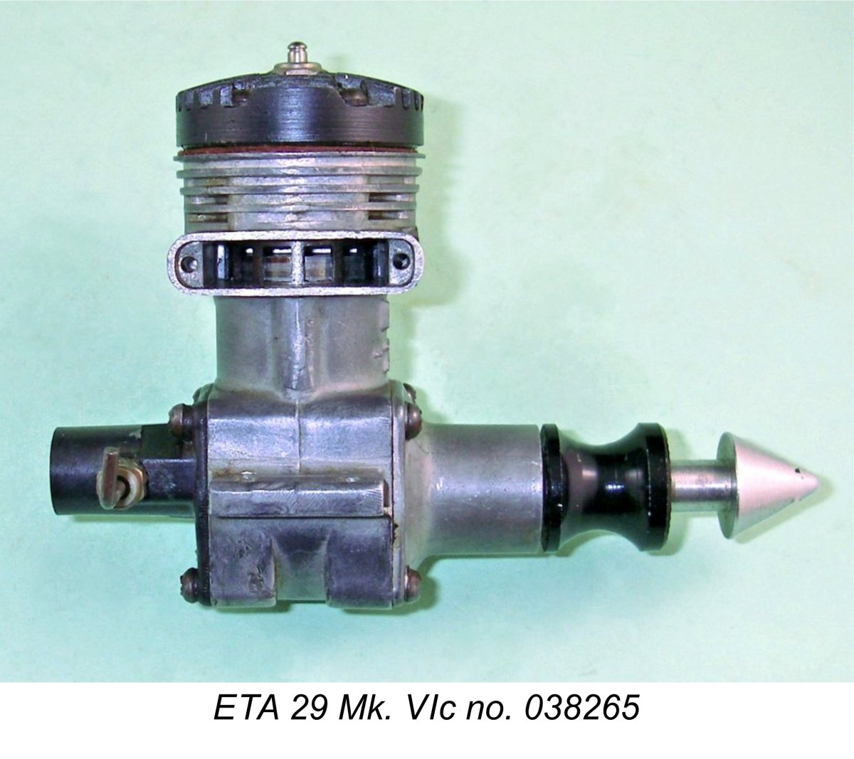
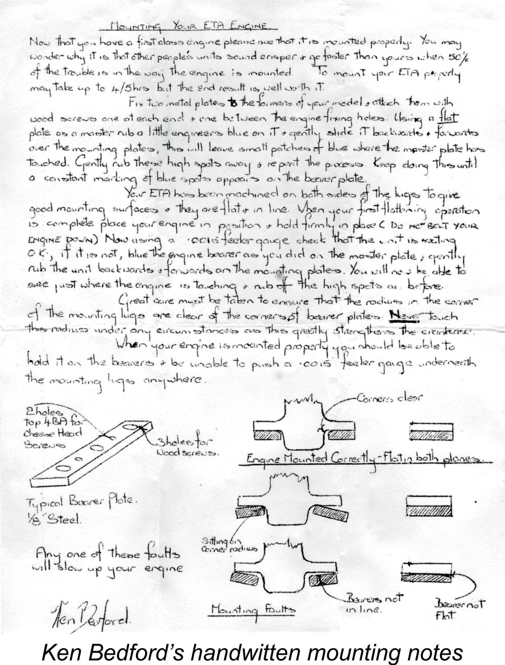 One of the things which was really noticable when dealing with Ken Bedford was his constant concern to assist his customers in every way possible to get the best out of their engines. Every boxed ETA 29 Mk. VIc of my personal acquaintance was supplied with a hand-written sheet of instructions for mounting the engine securely in a way that resisted vibration without inducing any crankcase distortion. As every user of high-performance model engines knows, the provision of such a mount is crucial if the engine is to give of its very best. Full marks to Ken Bedford for his care in this regard!
 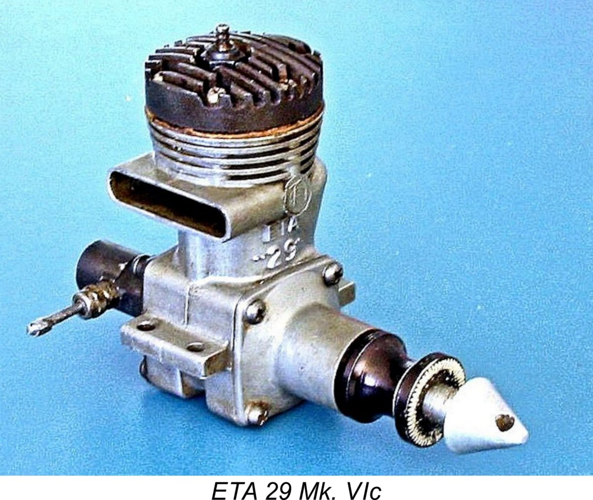 My other two Mk. VIc engines, which I purchased new direct from the factory in March 1965, are both examples of the later type with tapered aluminium spinner nut and provision for muffler attachment. They bear the serial numbers 038265 and 196265. Both are very early examples of this final version of the engine, having been manufactured in February 1965 as numbers 38 and 196 in the overall series.
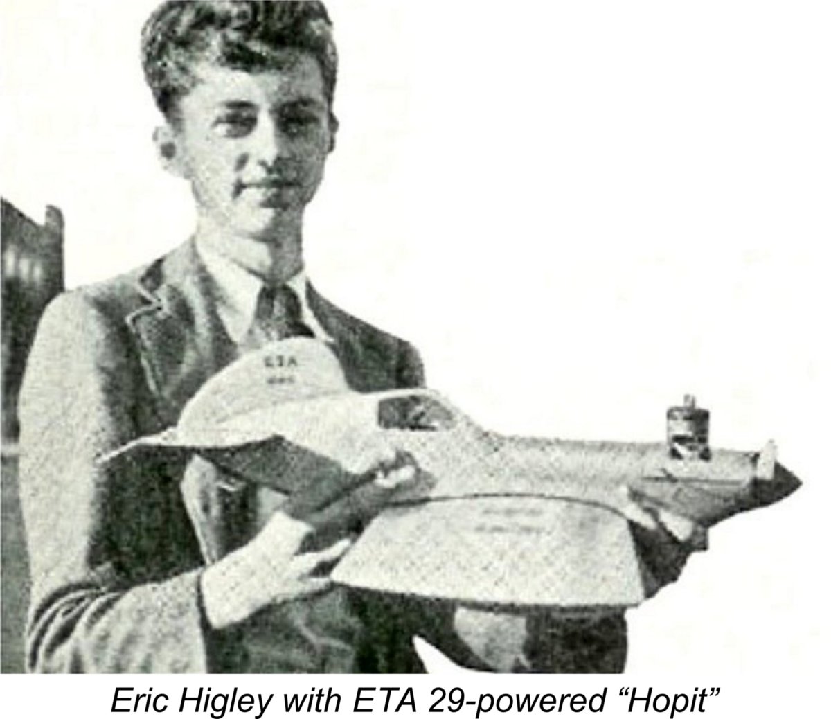 Oddly enough, the applicability of the ETA 29 was by no means confined to all-out racing events. When fitted with a spraybar in place of the standard surface jet needle assembly, the engine had excellent suction and needled very well provided one kept the revs up. A number of British and Australian stunt fliers used the engine to good effect during the 1950’s prior to the arrival of purpose-built stunt engines like the Merco range. The ETA 29 is to be seen as one of the “plan” powerplants in a surprising number of commercial plans for British stunt designs of the early to mid ‘fifties. Eric Higlett, seen here with his ETA-decaled "Hopit" short-coupled stunt design of 1951, was such a user, and he was far from being alone.
 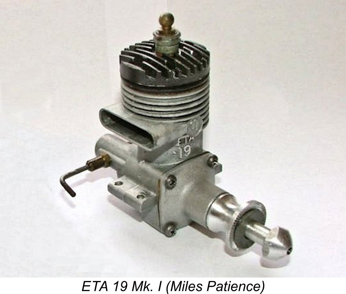 For completeness, it seems appropriate to include a very brief summary of the history of ETA’s “other” racing glow-plug engine, the ETA 19. This engine was evidently created to cater to the S.M.A.E. Class III speed category which then existed. However, it also seems likely that Ken Bedford entertained hopes of making some inroads into the US market. Prevailing AMA rules allowed engines of up to .199 cuin. displacement in their Class A competitions.
 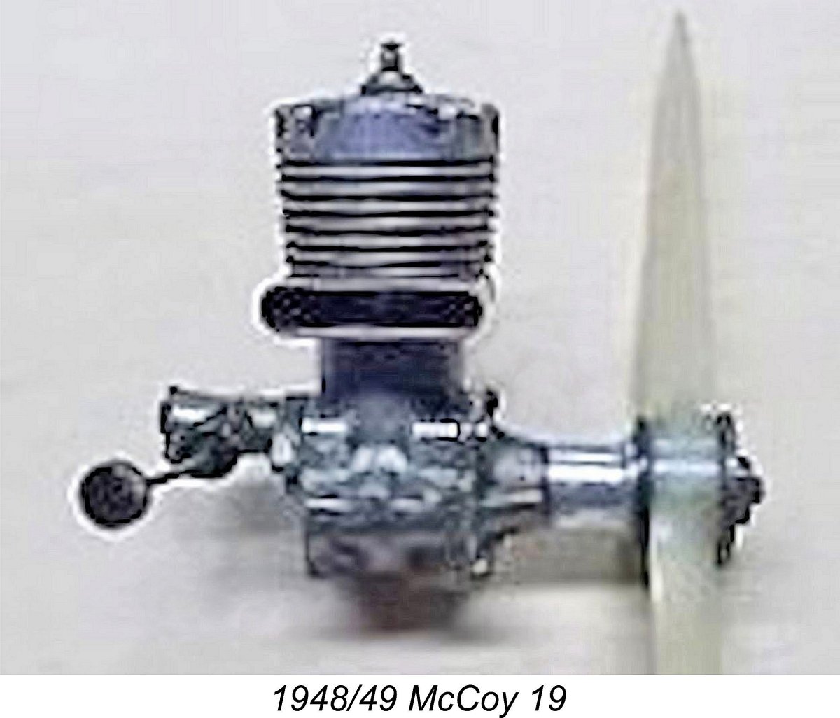 Readers will recall that the ETA 29 was designed following Ken Bedford’s examination of a McCoy 29. The design of the ETA 19 also clearly paid tribute to Dick McCoy’s efforts, bearing a strong resemblance to the then-current version of the McCoy 19. Ken clearly got his hands on an actual example of the McCoy for direct examination and test, since he took the trouble to develop his own performance curves for the McCoy 19. These have been preserved thanks once again to the diligence of Miles Patience.
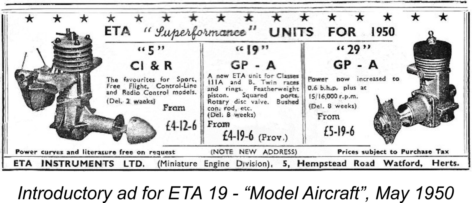 The earliest advertisement for the ETA 19 in my present possession is the ETA placement which appeared in the May 1950 issue of “Model Aircraft”. The engine must have been in the process of introduction as of that date, perhaps as a market-testing exercise, because the quoted price of £4 19s 6d (£4.97) was qualified as being “provisional”. A delivery time of 8 weeks following receipt of order was cited, implying that production was just then getting underway and was being initiated on an "order book" basis, presumably to assess the level of interest in the engine. The reader was reminded of the need to "note new address", since this was the first advertisement placed from the 5 Hempstead Road location in Watford.
 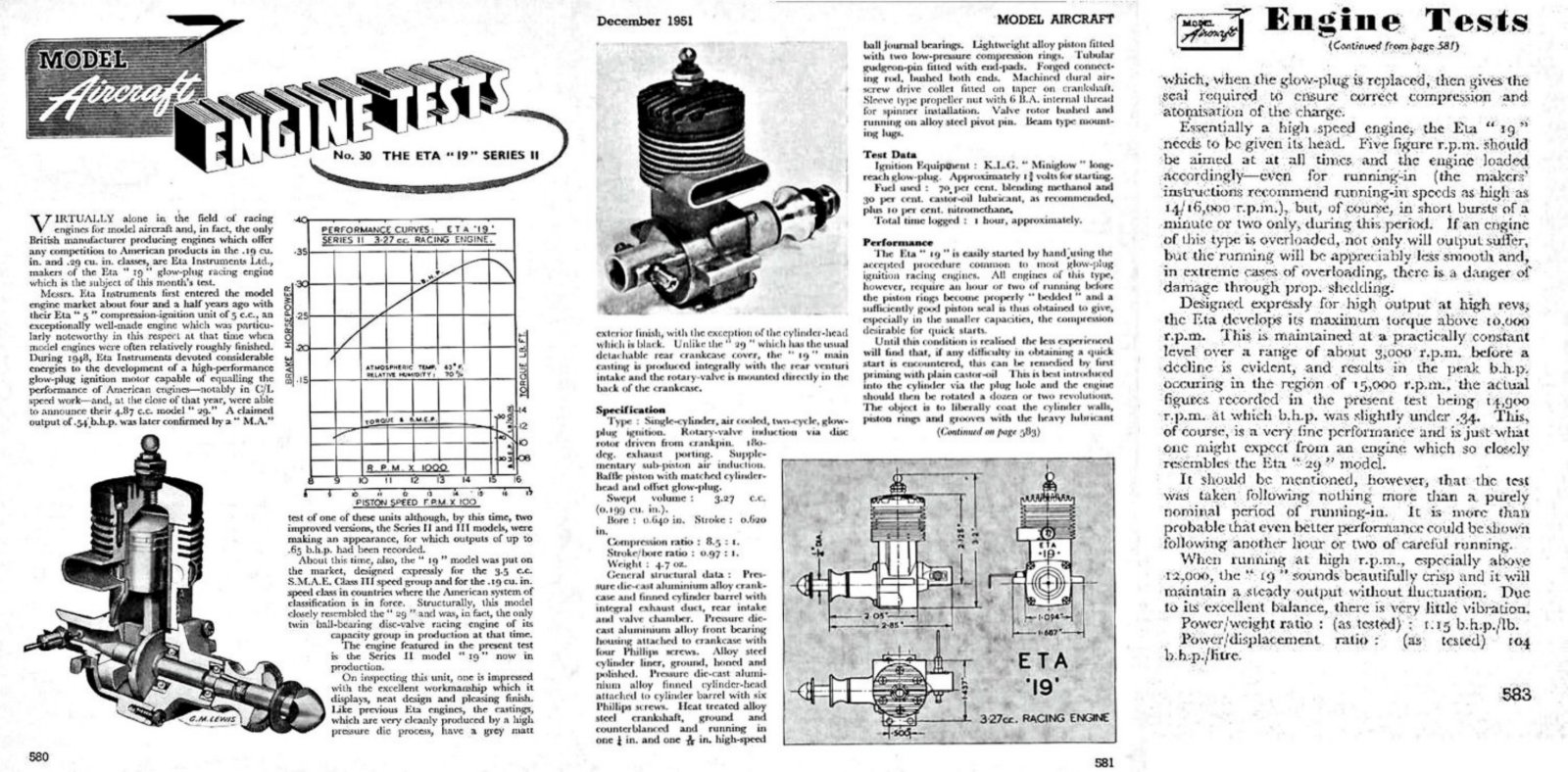 The engine fared extremely well in Chinn’s hands. Using a fuel containing 15% nitromethane, he measured a peak output of 0.338 BHP @ 14,800 RPM, a very good figure indeed for a glow-plug motor of this era and displacement. He praised the engine’s construction very highly, citing the “excellent workmanship which it displays, neat design and pleasing finish”. Reading between the lines, it appears that the seal
 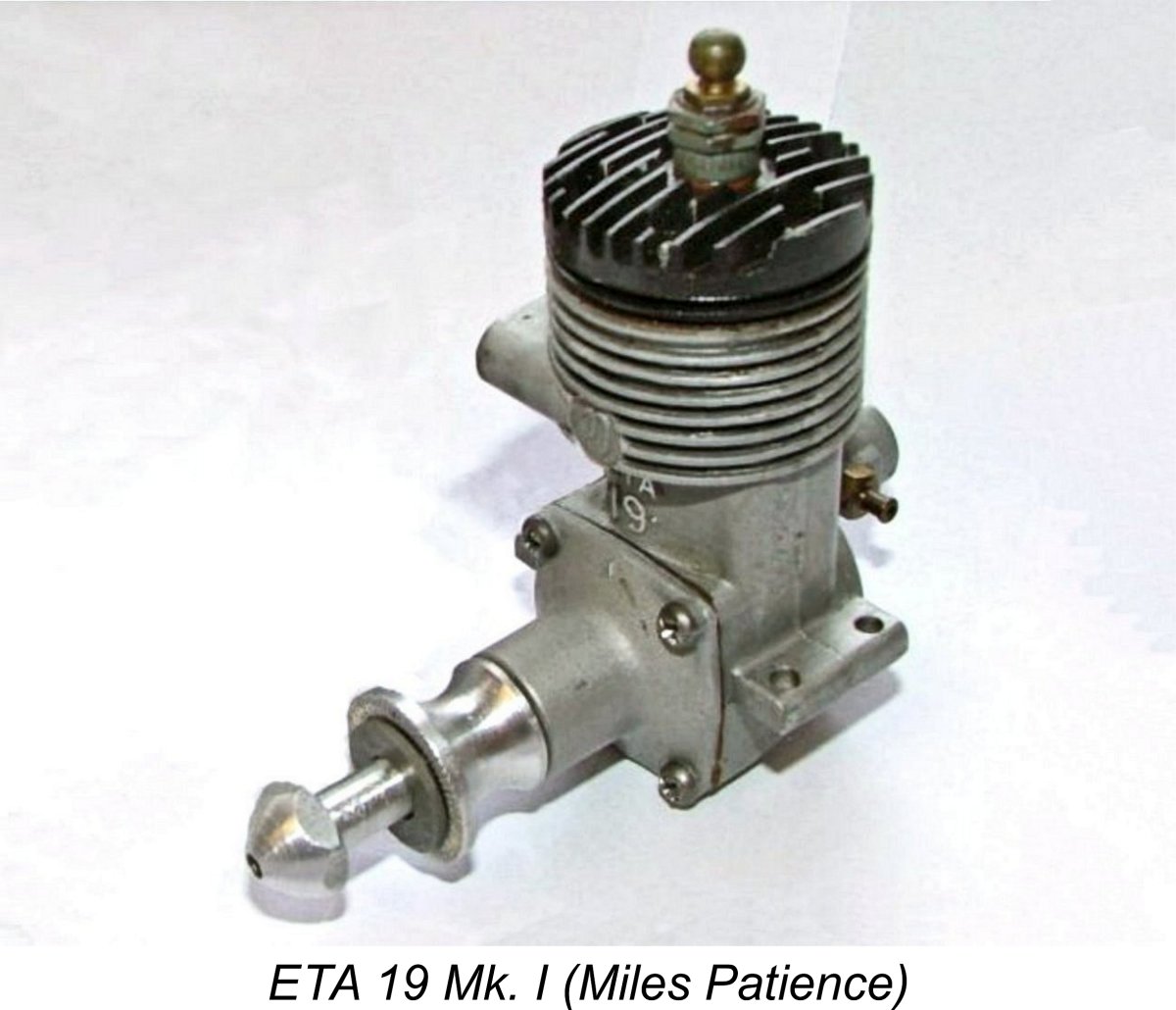 provided by the rings when new was less than perfect, since Chinn commented on the need for a period of 1–2 hours running to bed in the rings. He recommended that in the interim a castor oil prime be administered to create a sufficient seal for starting. Other than that, he characterized the engine as being easy to start by hand using standard procedures. Vibration levels were said to be very low.
 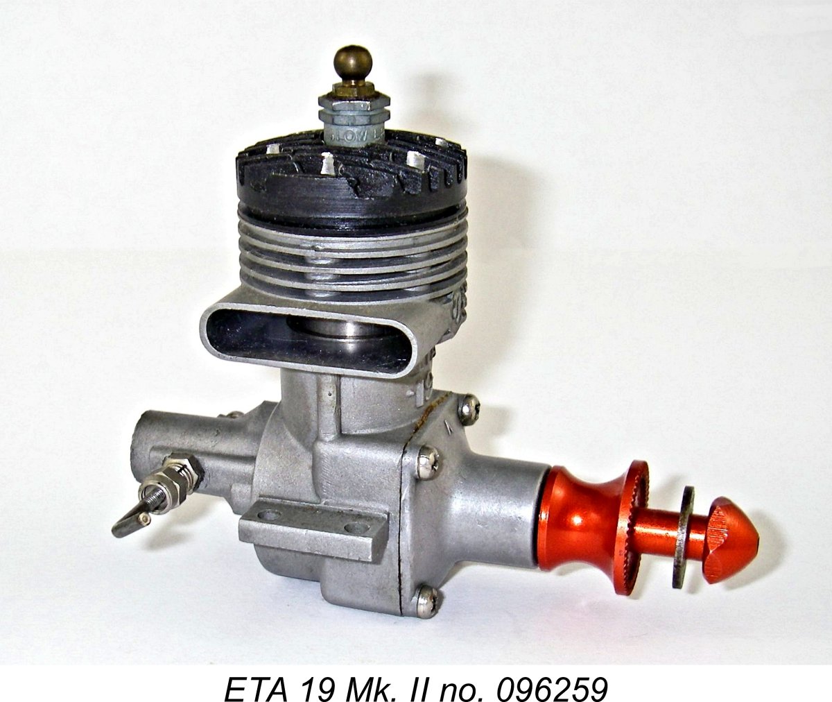 The revised version of the ETA 19 used a crankcase which appeared to have been formed using a slightly modified version of the original die. The bypass passage shape was slightly altered, while the rear of the case was “decorated” with a series of horizontal extrusions. This is another giveaway feature allowing instant identification of this variant.
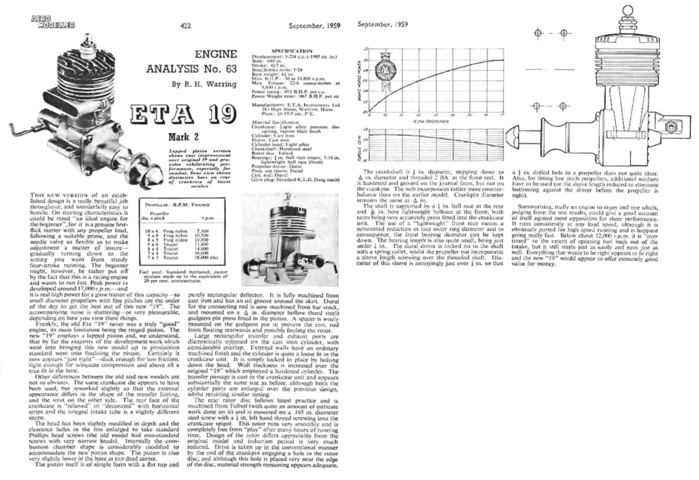
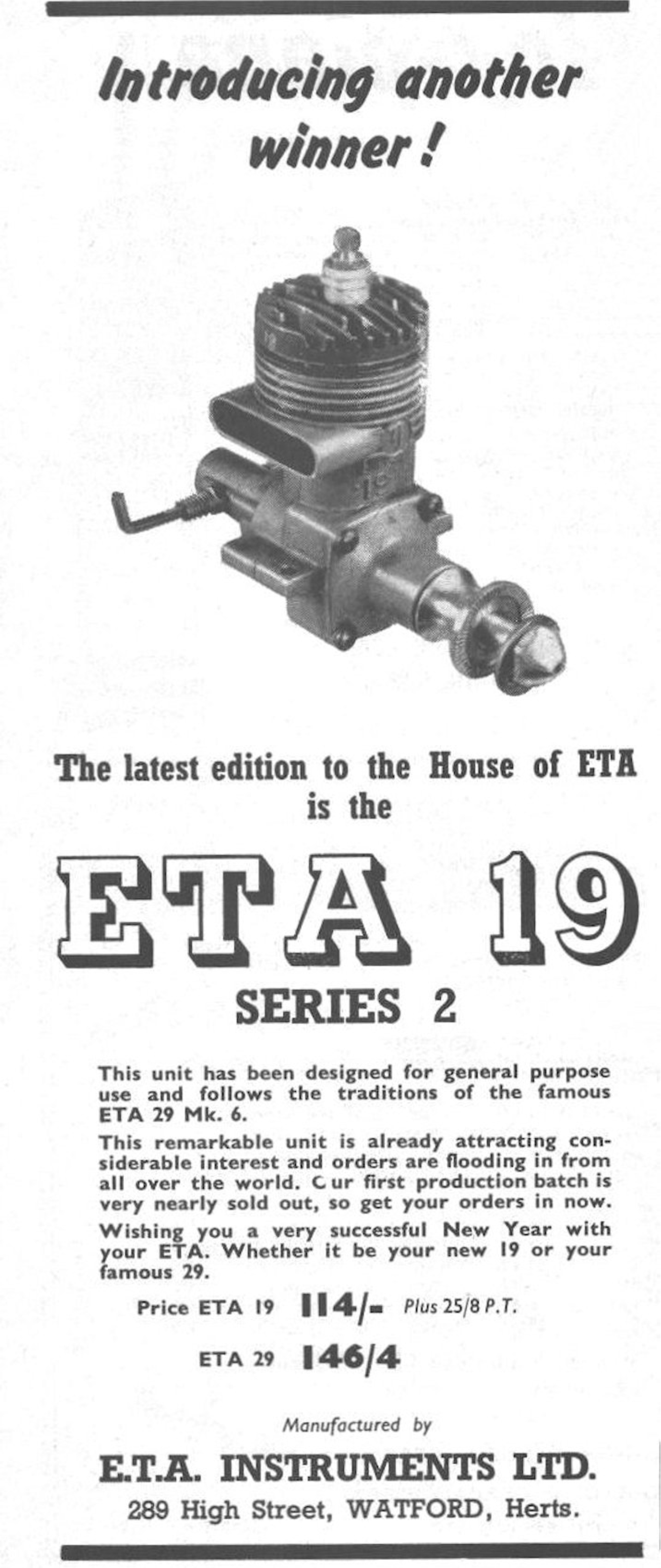
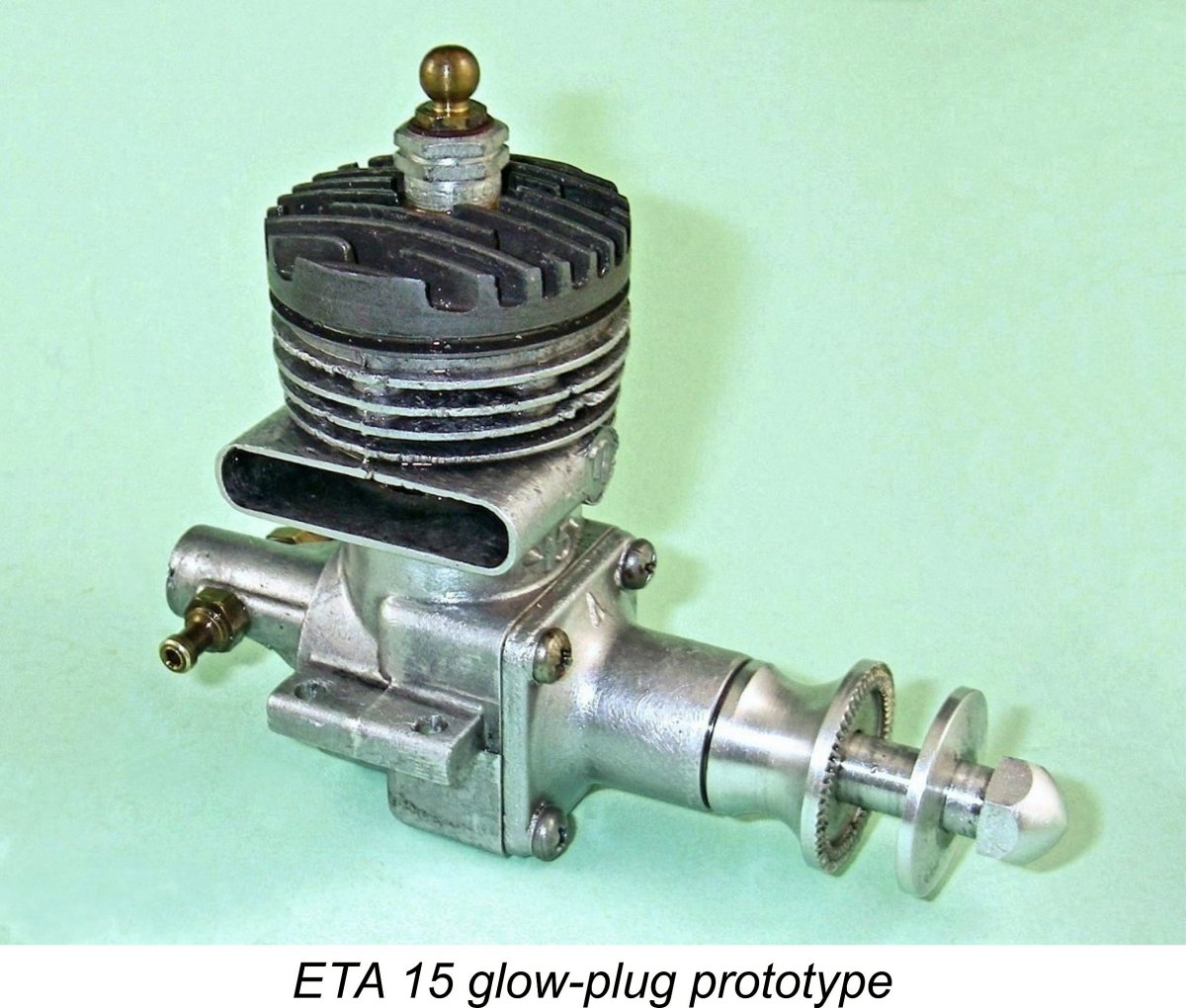 who discovered a collection of components for this variant, presumably from Eric Bedford's estate. There was enough there to build at least one complete engine, along with many of the key components required to build four more.
 | |