
|
|
Twin-Cylinder Trickery – the G-Mark .12 Opposed Twin By Adrian Duncan with Ron Chernich
In essence, this article is a revised and significantly expanded re-publication of an earlier piece written by my late and much-missed mate Ron Chernich. Ron’s original article appeared on his wonderful “Model Engine News” (MEN) website in June 2006. However, Ron left us well before his time without sharing the access codes to his heavily-encrypted website, making it impossible to carry out any maintenance. Consequently, the site is now exhibiting unmistakable signs of deterioration as various links fail progressively with no opportunity to repair them. I’m not willing to risk the potential loss of Ron’s efforts due to this enforced lack of maintenance, hence my decision to re-publish this and other MEN articles on my own website. This re-publication of the article includes all of Ron’s observations relating to this very interesting little engine. I have taken the liberty of re-organizing the material somewhat, also adding a few of my own observations. However, the article remains every bit as much Ron’s work as mine. With that acknowledgement duly recorded, here goes…………….. The Manufacturer
From around 1961 onwards, Citizen and its associated companies initiated the external sale of machine tools, also expanding their activities into the international marketplace. As the Kawaguchiko Seimitsu company grew in scale, it began making products other than timepiece components, ending up with five independent facilities making watch components, measuring instruments, precision machinery, office equipment and experimental manufacturing process development. Although the main priority was still responding to the demand for components from the timepiece industry, the company began looking into fields in which the micro-level precision machining technology and mass production capability developed through its support for the timepiece industry could be utilized. In 1970 the company developed one of the world’s pioneering CNC automated lathes, which was given the name “Cincom” in an allusion to the parent company. A dedicated Precision Machinery Division was established in 1971. It so happened that the President of the parent Citizen Watch Co. at the time was an aeromodeller with a keen interest in model engines. He persuaded Kawaguchiko Seimitsu Co. Ltd. that the manufacture of model It’s not known who the designer of the resulting G-Mark engines was, but he seems to have been both capable and innovative. His first design was a 0.49 cc (0.030 cuin.) glow-plug unit which was marketed as the G-Mark Hummingbird in both un-throttled and R/C guises. This cute little radially-mounted engine weighed only 32 gm (1.15 oz.) in its bare state without the tank, throttle and muffler. It swung a matching 4½ x2 airscrew with considerable The range expanded in 1976 with the appearance of a 1 cc model for which both a two-piece silencer and an R/C throttle were made available as optional extras. Bore and stroke of this little motor were 11.2 mm and 10.6 mm respectively for an actual displacement of 1.045 cc (0.0637 cuin.). This engine was quite a useful performer – in his somewhat belated published test which appeared in the January 1985 issue of “Aeromodeller” Mike Billinton reported an output of 0.133 BHP @ 19,000 RPM for the unthrottled version with an open exhaust on 25% nitro. Use of the silencer reduced this to 0.109 BHP @ 17,200 RPM – still an acceptable performance for sport-flying applications. This test reprort is odd in that it was published nine years after the engine's introduction and over 4 years after its replacement with the Mk. II model mentioned below!
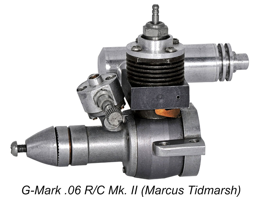
1980 was a big year for G-Mark. First, an improved Mk. II G-Mark 0.06 was introduced. This was a totally new design with an entirely new cylinder and crankcase along with modified bore and stroke dimensions. It was supplied with a silencer and R/C carburettor as standard equipment. Since this variant was never the subject of a published test, I have no further information. The most ambitious engine ever produced by the company also appeared in 1980. This was their remarkable 5- Perhaps somewhat unexpectedly given all of this complexity, the G-Mark radial was actually quite a good runner, although it required an electric starter to get it going. In his test of this unit which appeared in the September 1980 issue of “Model Airplane News” (MAN), Peter Chinn reported that the engine ran well and developed some 0.43 BHP at between 17,000 and 18,000 RPM. Despite the very high pitch of the sound produced by up to 90,000 exhaust discharges per minute, Chinn actually commented that the engine was “surprisingly quiet” in operation, presumably due to its use of an exhaust gas collector which discharged exhaust gases from all five relatively small cylinders through a single outlet in an almost continuous stream rather than a series of high-pressure pulses. Given the engine’s comparatively high peaking speed, Chinn suggested a 9x4 airscrew as the ideal prop. A video of one of these engines running may be found here.
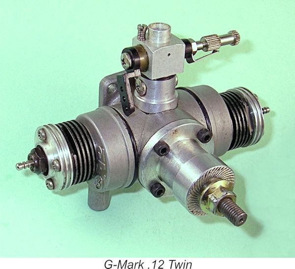
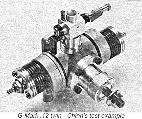
Although the boxer twin's peak output was somewhat below that of the 5-cylinder radial, that peak was delivered at significantly lower RPM, indicating greatly enhanced lower-end torque development. Having more low-end torque, it could swing a significantly more substantial airscrew at useable speeds - Peter Chinn considered 10x4 or 10x5 props to be well suited to the engine. Moreover, the 30 twin was more compact, a little lighter and far less complex that its radial relative, besides being simpler to operate and cheaper to buy. As a bonus, 2 glow-plugs are far cheaper than 5!! At this point, the level of energy being brought to bear on the company’s development program took a sharp downward turn – no new models were to appear after 1981. The driving force behind the design and production of these engines had evidently been the President of the parent Citizen Watch Co., who was an aeromodeller and keen model engine aficionado. He seems to have died in 1981, being replaced by an executive with no aeromodelling interests. The G-Mark model engines continued to be manufactured for a few more years, probably out of respect for their now-deceased instigator, but at some indeterminate point during the mid to late This was a great pity, because the company had shown itself to be both an innovative designer and an eminently-capable producer of high-quality model engines of considerable design distinctiveness. All of the engines produced under the G-Mark label had been manufactured to watch-maker standards of precision - their pressure die-castings were particularly notable for their quality. On the strength of these attributes, they had become established in the world market, with Cannon Electronics Inc. of North Hollywood, California acting as their US distributors and Irvine Engines of London handling their UK sales. They were seemingly set for a long tenure in the international model engine market, but sadly it was not to be. The Citizen Watch Co. remains very much in business today as one of the world's leading manufacturers of high quality state-of-the-art timepieces. Kawaguchiko Seimitsu Co. Ltd. also continues to operate as a wholly-owned Citizen subsidiary. Time now to join Ron Chernich in taking a look at a representative example of the G-Mark range which is on hand – the G-Mark .12 cuin. opposed twin of 1979. The G-Mark .12 Twin Evaluated
Chinn’s test of the engine was extremely favourable. He found that the little Twin was easy to start, also running very smoothly with minimal vibration, as might be expected from an opposed twin. Throttle performance was also found to be unexpectedly good – using a 7x4 airscrew, the engine could be throttled down from around 14,000 RPM to a safe idling speed of 3,500 RPM with good recovery and reliable mid-range operation.
A factor in Chinn’s somewhat modest initial expectations may have been his previous experience with opposed twin two-strokes, especially small ones. As noted elsewhere in various articles on MEN, and setting aside elaborate Scotch yoke schemes, this type of engine must be simultaneous-firing in order to use the crankcase as a transfer pump in the normal way. Designers of such engines face two problems - attaching the conrods to the necessary two-throw crankshaft; and delivering an equivalent charge of fresh mixture to both cylinders during transfer and scavenging.
Induction is also a challenge. The double-throw crankshaft results in the two cylinder axes being offset (unless the conrods are offset from the centerline, as in the Ross boxer engines). A single rotary valve, either front or rear, will generally lead to some degree of starvation of the cylinder furthest from the point at which the mixture enters the crankcase. Solutions to this problem inevitably add complexity. The Davies-Charlton Tornado used both front and rear rotary valves fed from a common central carburettor. Some German designers have used the central crankshaft web as a form of "drum valve" in an attempt to equalize the feed. This works, but requires German levels of precision to do so. Others opt for a centrally located reed valve, accepting that this makes induction somewhat symmetric and renders the engine prone to starting backwards. As usual, there are no easy answers and no such thing as a free lunch. G-Mark's Novel Solution
In fact, there are two grub-screws. They lock in place an insert disc that locates in a recess in the unusually deep front crank web. The two crank throws are integrally machined on opposite faces of a central crank-disc which is a totally separate component. This latter disc is drilled out to provide some degree of gas flow between the throws. One of the crankpins is longer than the other and slips into a hole drilled in the front web so that it partially overlaps the central cavity. A crescent relief on the pin allows the insert disk to both align and lock the central crank-disc section in place after the front rod has been placed over its crankpin.
However, this issue is somewhat offset by the fact that with both pots firing (or not firing), operational shear stresses on the front crankpin will be balanced at all points of rotation. Consequently, the front crankpin effectively only has to deal with the relatively small torque impulses generated by the rear cylinder – of the order of 14 ounce-inches at the pin if the torque measurements published by Mike Billinton and Peter Chinn are any guide. With good-quality steel, that shouldn't be a problem. In any case, you can't argue with success, and operational experience has amply validated the practicality of this unusual design.
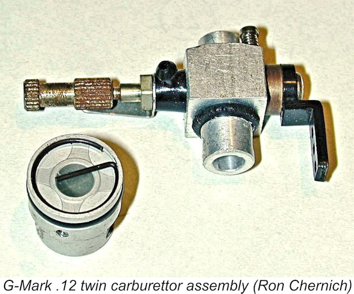
Like the piston/rod assemblies, the cylinders are rather Cox-like, with twin opposed exhaust ports and opposed internal bypass/transfer flutes. Chinn measured the exhaust duration at 134 degrees, with a transfer period of 112 degrees, both very conventional figures. The cylinders retain the exhaust collector rings, pressing them onto "O" rings that sit in cast-in grooves. The collectors are identical, located and locked against rotation by a raised arc cast into the rim. The offset hole for the cylinder in the collectors has the neat effect of aligning the twin exhausts laterally – a very clever design feature. Unlike the Cox design, the turned alloy cylinder heads attach to the cylinder with four slot-head screws and accommodate conventional glow-plugs. The crankshaft journal is stepped, 9 mm at the rear and 7 mm at the front. The shaft is carried in two ball races mounted in a turned aluminium housing. The front bearing only is of the sealed type. The assembly is secured to the case by four socket-head screws. The prop driver locks to the shaft with another grub-screw The reed valve is mylar, housed in a cylindrical turning that plugs into the crankcase. It is sealed by another "O" ring and secured by a 2 mm Phillips-head screw whose head is recessed into the rear of the radial mounting flange. The reed design and its retention spring are again distinctly Cox (of the "old" star pattern). The R/C throttle plugs into the center of this assembly with yet another "O" ring and two cross-point screws. The throttle is quite conventional, being of the "non-compensating" type. It has a fixed air bleed hole and a screw to set the idle limit. Fuel inlet is provided by a neat molded nylon banjo. Not so neat is the molded nylon throttle arm. As molded, this would have interfered with the crankcase, so the tip has been circumcised with side-cutters. Both Ron’s example and my own unit exhibit this “modification”. This, and the prop nut, are totally out of character with the very high level of quality exhibited by the rest of the engine, but both features are completely original. Packaging
The instructions which came with the engine suggest 20-25% nitro in the fuel. The papers with Ron’s example are dated November 15, 1979. At this time, a full factory reconditioning of the engine could be had at a cost not to exceed $76.50. The speed range is quoted as 2,800 to 14,000 rpm with a 7x4 or 8x3 prop. The instruction leaflet shows the three possible arrangements for lighting up the plugs:
Conclusion
From an innovation perspective, the design should be an inspiration to designers of small, opposed twin two-strokes. Yes, a high degree of precision would be required to hold the central crank-disc section while machining the crescent on the front crankpin that both aligns and locks the thing together, but no more than a careful worker who is prepared to spend time making jigs is capable of. The real eye-opener is how light the crankshaft for such an engine can be and yet deliver reliable, outstanding performance. Summing up, a very innovative and extremely well-made model engine which did both its designer(s) and its manufacturers great credit! __________________________ Article © Adrian C. Duncan, Coquitlam, British Columbia, Canada First published March 2026
|
 In this article, I’ll present some information on one of the more interesting Japanese model engines to appear in the post-classic era – the 1979 G-Mark opposed twin of 2 cc (0.122 cuin.) displacement. This cute little opposed twin-cylinder glow-plug motor displays a number of extremely interesting design features, also performing at an unexpectedly high level.
 One aspect of the G-Mark .12 twin that Ron didn’t cover was the history of the company that manufactured it. This was the Kawaguchiko Seimitsu Co. Ltd. (Kawaguchiko Precision Co. Ltd.) of Tokyo, Japan. This company had been established in 1949 by the prominent long-established Japanese watch manufacturer Citizen Watch Co. Ltd. as a manufacturer of precision wristwatch components on behalf of the parent company. During the 1950’s it expanded into the development of leading-edge machine tools, particularly those required for the manufacture of small high-precision components such as those required for timepiece construction.
 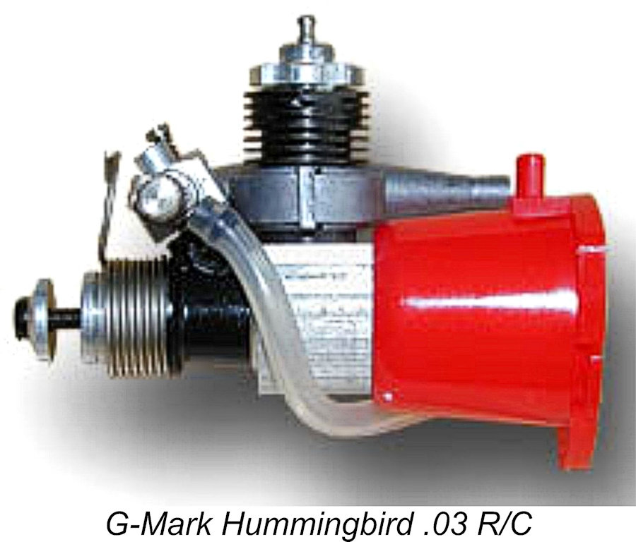 engines was a field in which their state-of-the-art small-component precision manufacturing capabilities could be applied very effectively. A new entity called G-Mark Inc. was established in Tokyo to market the engines, and the G-Mark model engine range was born.
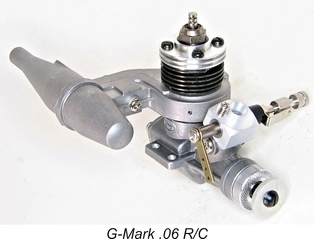
 In 1979, G-Mark introduced the main subject of this article, the G-Mark 2 cc (0.122 cuin.) opposed twin with R/C throttle and twin mufflers fitted as standard equipment. This twin was of course based upon the use of two 0.06 piston/cylinder sets. Much more of this model in its place below.
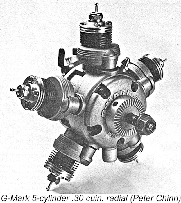
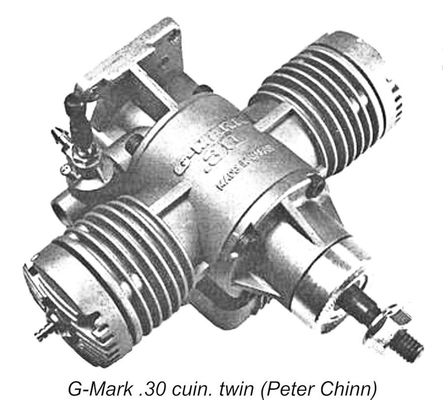 The final new model to appear under the G-Mark trade-name did so in 1981. This was the company’s 5 cc (0.30 cuin.) Schnürle-ported simultaneous-firing "boxer" flat twin. In his
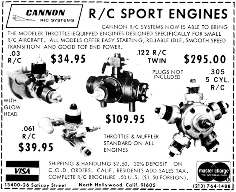
 When he reviewed this engine in the
 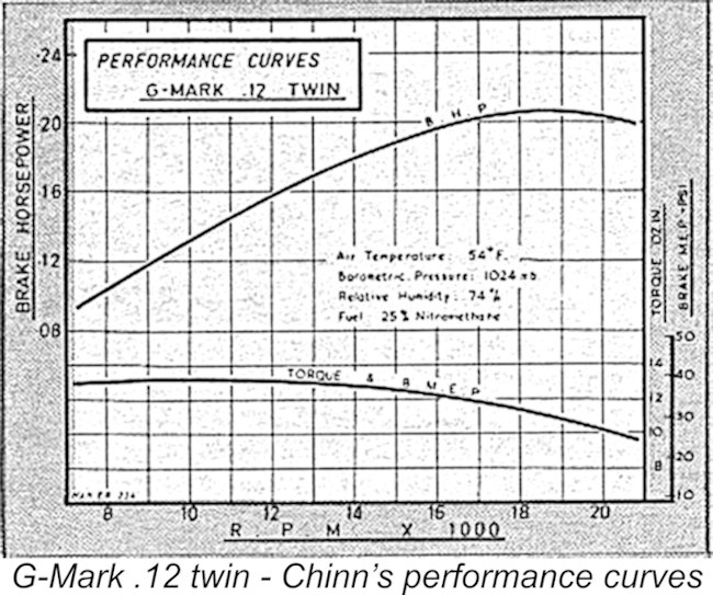 Chinn commented that the G-Mark performed “much better than we had expected”, delivering a peak output of 0.205 BHP @ 18,700 RPM on 25% nitro, by no means a dismal performance for a muffled 2 cc R/C sports glow-plug motor weighing only 146 gm (5.15 oz.). A 7x3 or 7x4 prop seemed to be the appropriate sizes to use in flight - the manufacturers also suggested an 8x3. Overall, Chinn characterized the G-Mark .12 Twin as “a pleasing little motor”.
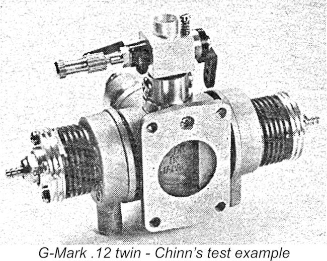 Amateur builders may opt for a permanent assembly, but commercial engines require a higher degree of serviceability, so normally some provision must be made to provide removable straps or caps on the big-end of the conrods. This leads to both complexity and bulk in the crankcase. Moreover, the smaller the engine, the more delicate the arrangement.
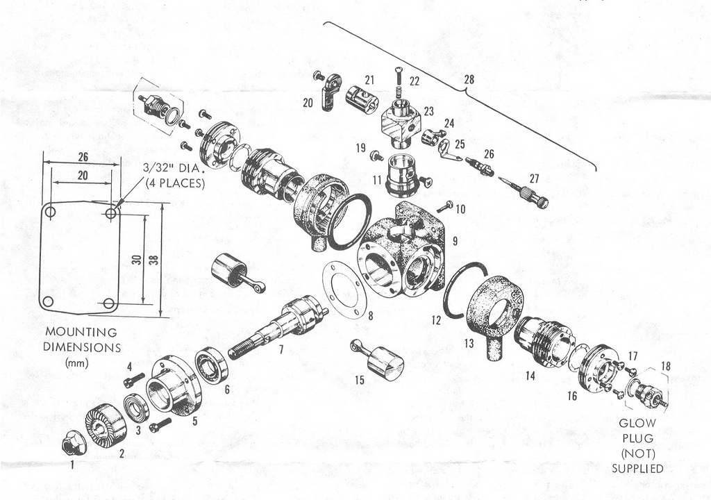 G-Mark's solution to the big-end problem was novel and surprisingly effective. As seen in the accompanying manufacturer's exploded illustration, the conrods are quite conventional, with a normal one-piece big-end and a ball-joint little-end a la Cox. Obviously, the rear one can just slip on, but as the shaft appears to be solid, how is the front rod attached? A close look at the drawing reveals a grub-screw in the front crank-web that provides a clue.
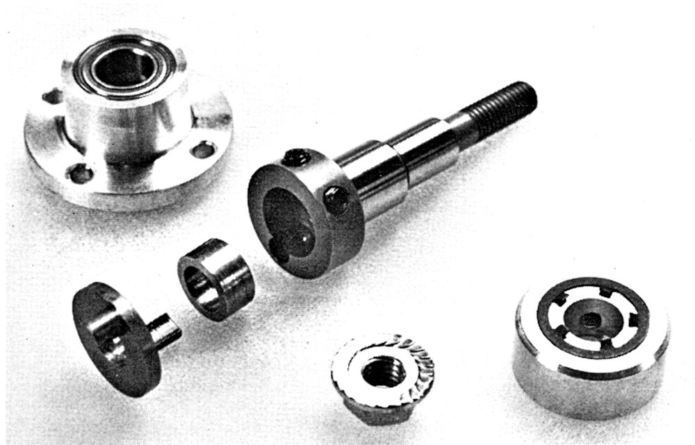 Now think closely about how you'd set up to machine something like this. It must assemble with the crankpins centered exactly on a common diameter of the front crankweb and equally displaced radially from the shaft axis on opposite sides. Tricky, especially as it must assemble like this "in the field" as well as in factory jigs. This worried Ron sufficiently that he did not attempt full disassembly for photographs. To be sure of alignment, he would have had to rotate the shaft in a collet with a dial test indicator on the central crank-disc. Safer to leave it alone as factory-assembled and use the MAN photo at the left to show the setup. It is interesting to note that on Ron’s example of this engine, the locking disk is solid, not a donut.
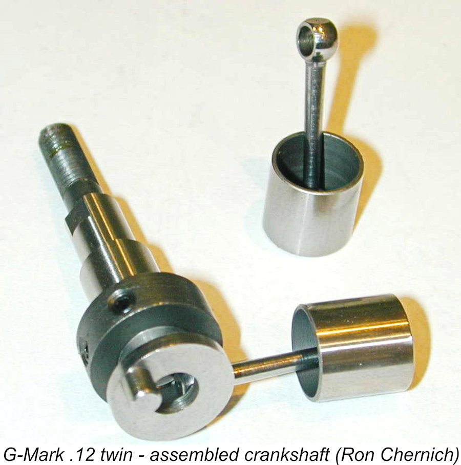 This shaft assembly appears at first sight to be somewhat "delicate". The front crankpin is the sole connection between the rear crankpin and the main crankshaft. Therefore, it has to accommodate the cyclic torque impulses generated by the rear cylinder unaided by any rear bearing, as was the case with the
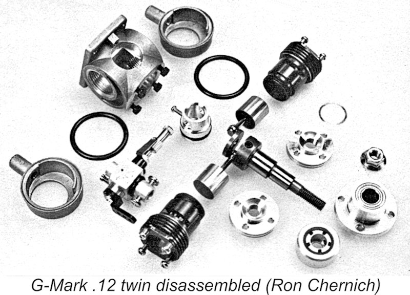
 that bears against a flat on the 7 mm front section. An unusual feature is the stamped, five-finger spring washer that sits in a recess on the rear face of the driver. The fingers are raised to press against the central portion of the front race, clearly to help control shaft end-float and keep the conrods aligned with their respective cylinder axes. The cadmium-plated prop nut is a commercial item that is forged with an integral washer.
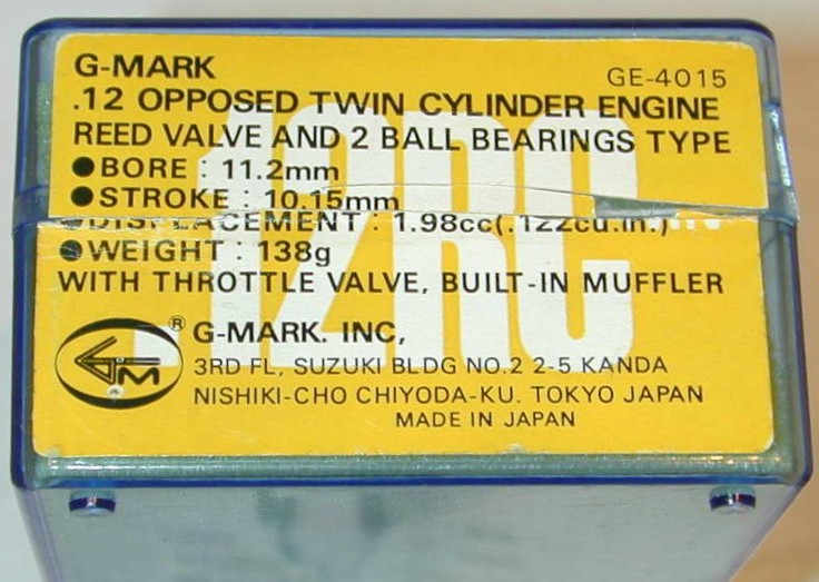 In the USA, the engine was distributed by Cannon R/C systems (Ron recalled building and flying several of their propo radio kits, which were well designed and performed well). His New-in-Box example was one of their units. The engine was supplied in the illustrated injection-molded plastic box, embossed with the manufacturer's logo and fitted with a foam insert to accommodate the engine. My own example has been mounted and run, but remains in Like-New condition, although it has no box.
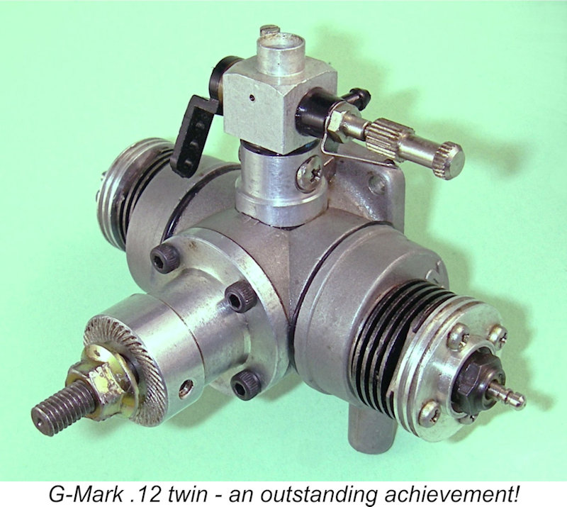 Ron commented in conclusion that he really should give his little G-Mark twin a run. I don’t know if he ever did so. MECA rules allow you to call an engine "NIB" even if it's had a test run or two, but given its pristine condition (and what he paid for it!), Ron was reluctant to see Peter Chinn's praise confirmed. I feel the same way about my own near-pristine example – for me, Chinn’s performance evaluation is good enough!
 | |