
|
|
Rescuing a Rust Bucket - Model Engine Restoration
Many people lose interest as soon as this condition becomes apparent. However, in doing so they may be passing up an opportunity to acquire an interesting old engine at a very reasonable price. I say this because under all that grime, rust and goo many such engines actually remain in surprisingly good restorable condition. This applies particularly to those that have been put away without flushing or lubricating with after-run oil (as many of them were) after being run on a fuel containing castor oil, which is actually one of the best long-term metal preservatives of them all. The external surfaces may be etched and pitted through corrosion, but the internal components may well be perfectly sound. This speaks to one of the primary goals of this article, which is to encourage people not to be too quick to condemn an engine as unrestorable purely on the basis of its external appearance. It really is amazing what can be achieved with some seemingly hopeless cases! It's well worth taking the time to look a given rust bucket over quite carefully to determine the feasibility of restoring it to an operational state. As the old blues classic says: "Ya Cain't Judge a Book By Lookin' at its Cover!" Of course, two fundamental criteria need to be met in making the decision to undertake a restoration. Firstly, the engine has to be physically restorable using the range of available techniques, including cleaning everything up to an acceptable standard, making any necessary repairs and making or obtaining replacements for any missing or broken parts. A broken major casting or a fractured cylinder may represent show-stoppers in this context, for example. Secondly, the engine has to be worth the effort involved. A rare or unusual engine is inherently more worthy of restoration than a common-or-garden variety of which many good examples already exist.
Obviously, the lengths to which one may go in restoring a given engine will vary widely based upon the intended use of the unit (flying, display, resale) as well as its comparative rarity. A relatively rare engine, or one which is strictly intended for display or resale, merits a higher level of effort to restore its original configuration to the maximum extent possible. If on the other hand the engine is purely intended for nostalgia flying or recreational bench-running, restoration to completely original condition is less of an imperative than simply putting the engine back into good running order. In such cases, missing tanks, non-standard prop mounting components, incorrect needle valve assemblies and the like become relatively unimportant. In this article, I won’t dwell at great length upon the various techniques for cleaning the components once disassembled. I have covered the special techniques applicable to magnesium castings in a separate article to be found on this website. I’ve also covered the approach to removal of rusted-up nuts and bolts. I won’t repeat the majority of that material here except insofar as it applies to the specific projects discussed below. I will also steer clear of the re-assembly phase, since that varies greatly from one engine to another. All I will say here on that topic is - please use the correct tools and fasteners! For a successful reclamation of an engine in this somewhat discouraging category, there are a number of essentials which should be assembled in advance, as follows:
With the required equipment and supplies on hand, the next critical step is to fully assess the problem before making a start. It’s essential to go about the unsticking and dismantling process in the correct sequence, otherwise damage will almost certainly result. Obviously, the correct sequence may very well vary for different engines and varying conditions. Once the task is fully scoped out, the next imperative is to go at things slowly and methodically. Many of these processes simply won’t be rushed, and you just have to exercise enough patience to allow the various processes to take effect in their own time. At the first sign of significant resistance, back off and allow some more time for things to free themselves up. Don’t fight an engine that simply isn’t ready to come apart!! One final point before we get started - when planning to use any solvent or penetrating agent on an engine having a painted crankcase, make sure that the substance to be used will not act as a paint remover. Acetone is very problematic in this regard. Many an original finish has been lost or at least damaged through failure to pay attention to this point. Same goes for plastic tanks - some of the early ones can be irreparably damaged through contact with certain cleaning agents and solvents. I think that the best way to illustrate the steps involved in assessing a given engine and accomplishing its successful restoration is to go through a few examples of engines which I have restored myself and the techniques used to assess and reclaim them. Here goes!! A Significant Challenge
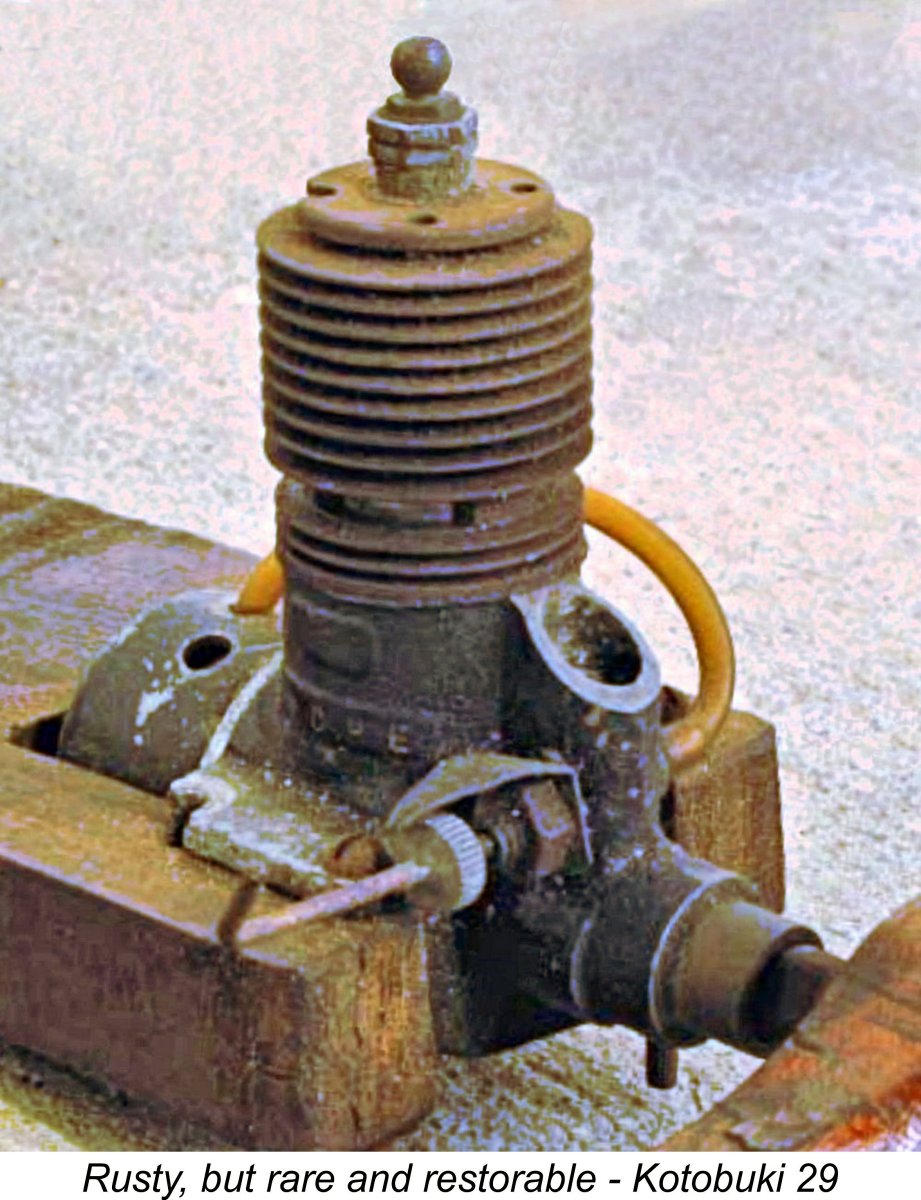
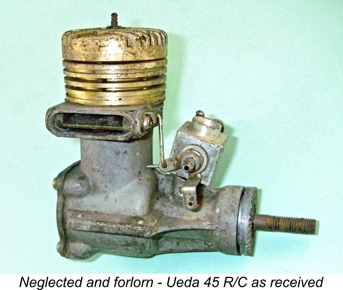
Well, the worst condition that I can imagine for a model engine goes quite a long way into the realm of seriously trashed, so I wasn’t unduly put off! I noted that the collection included a 1947 Mk. I Drone Diesel – a nice collectible which is one of my personal favorites. It seemed to be mostly all there. In addition, there was a 1966 O.S. Max-H 60 R/C, which is one of the less common 1960’s O.S. Max models today. Again, all of the important bits seemed to be there. The third restoration possibility was an example of the relatively rare early 1964 Ueda 45 R/C single plug model which looked almost complete and fully restorable. On the basis that I might be able to get these three engines back up and running, I bid on the collection and was successful in acquiring it, paying US$80 for the privilege. The other two engines were a Testors .049 which was pretty far gone and wasn’t worth restoring in any case, and the previously-illustrated terminally rusty O&R 23 with a broken crankcase which didn’t appear salvageable since the cylinder is welded into the case and is therefore not removable for cleaning or for fitting into a new crankcase. In any case, these engines are by no means uncommon. There was also an Enya muffler which didn't match either of the R/C glow-plug units or indeed any other engine in my collection, hence being of no use to me. Still, if I could get the first three less common engines back into good running order and in reasonable cosmetic condition, I would certainly realize a fair return on my $80 investment. When the engines arrived, I found that the seller’s description had been completely accurate. The engines dated from the late 1940’s up to the mid 1960’s. They appeared to have spent the last 50 years stored in a bucket in someone’s leaky and dusty garage or garden shed! There were clear signs of water damage as well as a good layer of dust, grit and grime. Heaving a sigh, I began the task of assessing them and working towards their restoration. For convenience, I’ll deal with the engines in turn, beginning with what proved to be the easiest one! 1966 O.S. Max-H 60 R/C
This example bears no serial number, but the letters “JB” appear neatly stamped beneath the right-hand mounting lug. I have no idea regarding their significance. The engine had clearly done some previous running and had evidently been mounted in a model if the witness marks on the mounting lugs were anything to go by. As received, the engine was seized solid with 50 year-old castor oil gum. It was also missing its prop nut, prop washer, needle and exhaust baffle plate. I was able to replace the first three items from my stash of original O.S parts, while the baffle plate would have to be made if the correct pattern could be established. That said, many of these engines (perhaps the majority) were operated with a muffler in place of the baffle, which almost certainly explains the baffle's absence in this case.
The key question was the condition of the internal working components. I was encouraged to note that the engine had clearly gone into the bucket without flushing after being run on a fuel containing castor oil, which is a superb metal protector. The visible cylinder walls and piston crown were liberally coated with castor gum. There were certainly grounds for optimism! When dealing with a frozen engine, the first step is invariably to determine the point in the operating cycle at which it has become frozen. In this instance, observation through the exhaust port confirmed that it had become frozen very close to bottom dead centre. On the one hand this was good, because that’s the best position in which to gain the mechanical advantage necessary to unstick the gummed-up piston in the bore by turning the shaft. On the downside, it meant that the cylinder and crankcase interiors (the latter through the open bypass) had both been exposed to the surrounding environment. I had to pin my faith on castor oil! Looking at the problem objectively, it was clear that the first step simply had to be to free the piston. I gave the entire engine a good overnight soaking in methyl hydrate (a good castor gum solvent), drained the internal cavities and then placed it in a domestic oven at around 200 degrees. After letting it sit for a while to give the castor gum time to soften, I removed it from the oven, fitted a wooden prop and squirted a little methyl hydrate into the hot exhaust. After that, a fairly hefty application of torque shifted the piston slightly, which was all I wanted at this stage.
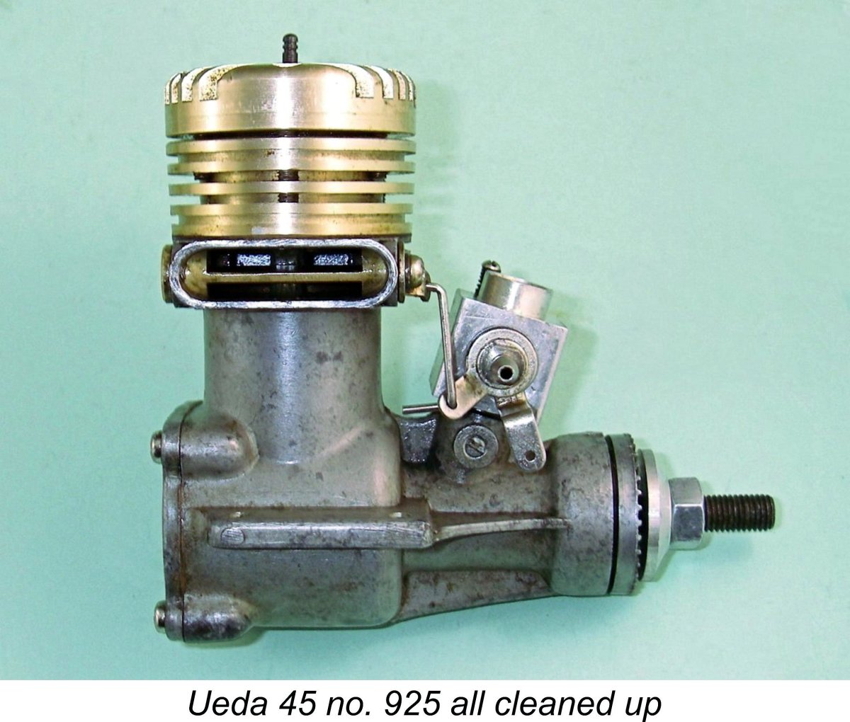
Now came the moment of truth! With the piston still at bottom dead centre, I removed the four machine screws that retain the front cover, broke the front end free from the case and carefully pulled it forward. This is why I had to make sure that the big end was free – if the rod didn’t slide easily off the crankpin, it would be easy to bend the rod. Thankfully, all went well - the big end bearing had been completely freed from the crankpin by my earlier efforts. At last the internals were exposed. Oh joy!! Rather to my amazement, they proved to be in perfect condition with not a trace of rust. The crankshaft bearings felt a bit on the lumpy side, but that was to be expected with all that castor oil gum. To deal with this, the front end went back into the oven, after which some ATF/acetone mixture was shot into the hot bearings. They immediately started to feel really good when turned over, and a further soak in the methyl hydrate followed by a little running on the lathe with penetrating oil finished the job. After this treatment, the bearings turned out to be in excellent operating condition, running absolutely smoothly. This being the case, I saw no reason to dismantle the front end further. This raises another point in connection with our topic - don't dismantle anything unnecessarily! The old adage of "if it ain't broke, don't fix it!" is very applicable here. Examination of the bore using a light through the plug hole and exhaust indicated that it was just fine apart from the layer of castor oil gum which had protected it all these years. I could see no reason to remove the cylinder head and thus potentially destroy the head seal. Accordingly, I confined my further activities to cleaning up the external surfaces using a range of solvents and brushes, after which I reassembled the engine. The piston was still around bottom dead centre, but was free to move in the bore thanks to my earlier "rocking" efforts. Now that I knew that the bearings and the bore were OK I could start to work it by degrees further up the bore, first heating the engine in the oven once more to soften the castor gum and then applying plenty of AFT/acetone mixture while still hot. After this, some more rocking of the prop back and forth by ever-increasing amounts got the still-hot piston moving progressively further up the bore with little detectable resistance, scraping off the softened castor gum as it went. In a surprisingly short time I had the piston up at top dead centre, after which the engine turned over completely freely with no plug fitted. All of the visible piston and ring working surfaces appeared to be in excellent condition. As far as I was concerned, the engine was now fully restored to running condition. There was doubtless a residue of The original O.S. idle bar glow plug with which the engine arrived was found to be in excellent condition, still ready for use. With that plug re-installed, compression seal was absolutely perfect, and there was no detectable play in any of the bearings. The engine even looked pretty good – most of the remaining surface blemishes were relatively superficial. All that was left was to find time and opportunity to give it a test run. I soon found such an opportunity. As usual when running a "recovered" engine for the first time, I first injected a healthy dose of molybdenum disulphide lubricant through the intake to deal with any residual irregularities in the working surfaces. With a Taipan 11x5 prop fitted, the engine proved to be very easy to hand-start (I don't even own either an electric starter or a chicken stick!) and ran superbly, proving itself to be a remarkably efficient converter of money into noise in the absence of a muffler! The throttle too worked very well despite the absence of an exhaust baffle. After a few runs the engine felt absolutely first-class, clearly all ready for hard work if anyone cared to put it back into vintage R/C service. So all that was left was to replicate that missing exhaust baffle if I can ever find a pattern……………might as well complete the thing. Another one brought back from the trash can!! 1964 Ueda 45 no. 925 Next up was the Ueda 45. I've covered the Ueda range in some detail in a separate article to be found on this website. None of the big Uedas are particularly common these days since they weren't made in large numbers. This particular example is actually one of the less common models – it’s the original single plug lapped piston version of the engine which first appeared in 1964 as Ueda's first offering, surviving into 1967. This example was the first such unit that I had personally encountered. As such, it appeared to be well worth restoring. The earliest variant of this model incorporated some rather odd cylinder port timing numbers, as recorded by Peter Chinn in his March 1967 test of the later version which appeared in “Aeromodeller” magazine. Because of the inappropriate port timing, Chinn recalled that he had only been able to extract a rather woeful 0.44 BHP @ 9,700 rpm from that original version of the engine.
As received, the poor old Ueda exhibited a healthy layer of accumulated dust and dirt along with clear evidence of water etching on the castings, although this didn’t appear to be deep. Like its O.S companion from the bucket described above, it was well and truly seized with 50-year old castor oil gum. One very encouraging indication was the fact that the gold anodizing on the cooling jacket and head showed no trace of fading. To anyone who knows the big Uedas, this implied that the engine had done very little running, since the head colour on these units fades quite rapidly with heat. The only missing parts were the prop nut and prop washer, both of which were replaced with stock items from my parts stash. I began this time by giving the engine a good external scrubbing with a combination of solvents and brushes. Thanks to its water displacement qualities, WD-40 actually works quite well as a finishing agent for this purpose, drawing any water residues out very effectively. After this, the Ueda looked surprisingly good! There was some mottling of the cast crankcase surfaces, but nothing too ugly. It all came down once again to the engine’s internal condition. As with the O.S. Max-H 60 described previously, the next order of business was to establish the point in the operating cycle at which the engine had become frozen. An examination of the visible piston wall and the crankshaft induction port (through the intake) proved that the engine was frozen part-way up the compression stroke with the induction port accordingly open. This was very good news from a cylinder preservation standpoint, because it meant that much of the bore and most of the piston skirt should have been well protected by the castor oil gum which had frozen the engine. Better yet, the fact that the glow-plug was still tightly screwed home meant that the upper cylinder had been isolated from the surrounding environment. I was now confident that the bore and piston would be in pretty good condition once cleaned up. However, the same could not be said for the bottom end components. The fact that the engine had been frozen with the induction system open meant that the crankcase had been in communication with the surrounding environment for all of those years. I was expecting to see evidence of this. The carburettor and its linked rotary exhaust baffle were totally frozen up with castor oil gum. I removed the entire assembly for separate cleaning, using the heat from a heat gun to soften the castor gum. Externally, the components cleaned up to near-mint condition through the use of a tooth-brush and solvent. A little more heat applied with the heat gun softened the internal gum to the point where the carburettor barrel was free to move, after which some working back and forth with plenty of methyl hydrate completely freed it up. I checked that the air bleed hole and fuel jet were clear, after which the now-pristine assembly was ready for re-installation.
My next step was to remove the backplate. This came off surprisingly easily, upon which all was revealed! It appeared that the engine had received a dose of water through the open intake which had pooled in the crankcase – there was a “high tide mark” of rust on the crankweb, and there was also a good layer of rust in the crankshaft induction passage through which the water had penetrated. However, the crankpin had thankfully stayed clear of this because the position in which the engine had frozen as well as the engine's clearly near-vertical orientation while stored in the bucket had kept it elevated above the water in the case. The only damage to the rear ball-race that I could see was some corrosion at the lower edge of the rear outer race which had evidently not extended into the bearing itself. The actual working components of the rear bearing looked very good – thank you, castor oil! The visible piston interior also looked completely corrosion-free, as did the rod. OK, freeing-up time!! As before, the domestic oven treatment was called for. Once the engine was good and hot, the trusty wooden prop went back on and all visible working surfaces and bearings were lubricated with ATF/acetone mixture. A fairly hefty application of torque to the prop in the reverse direction (pulling the piston downwards) broke the softened-up gum joints, the solvent wicked in by capillary action and the still-hot piston slid smoothly down to bottom dead centre as I slowly turned the prop by hand. A little cautious experimentation revealed that the engine now turned over quite smoothly with no evidence of the presence of particulates – as I had expected, the working surfaces of the piston and bore were in perfect condition under all that castor gum. The crankshaft turned extremely freely, with no evidence of lumpiness due to grit or corrosion pitting in the bearings. The portion of the main journal that was visible through the intake was almost completely corrosion-free - once again, the castor oil had done its job well. The corrosion was evidently confined to the internal gas passage and part of the crankweb. This being the case, I decided that further dismantling was unnecessary. As stated earlier, it’s never a good idea to disturb well-established joints involving gaskets unless you have no choice – doing so very often results in damage to the gaskets, necessitating their replacement. In addition, it’s unlikely that the parts will go back together in exactly the same orientation to each other, to some extent negating the effects of any previous running-in which may have been done.
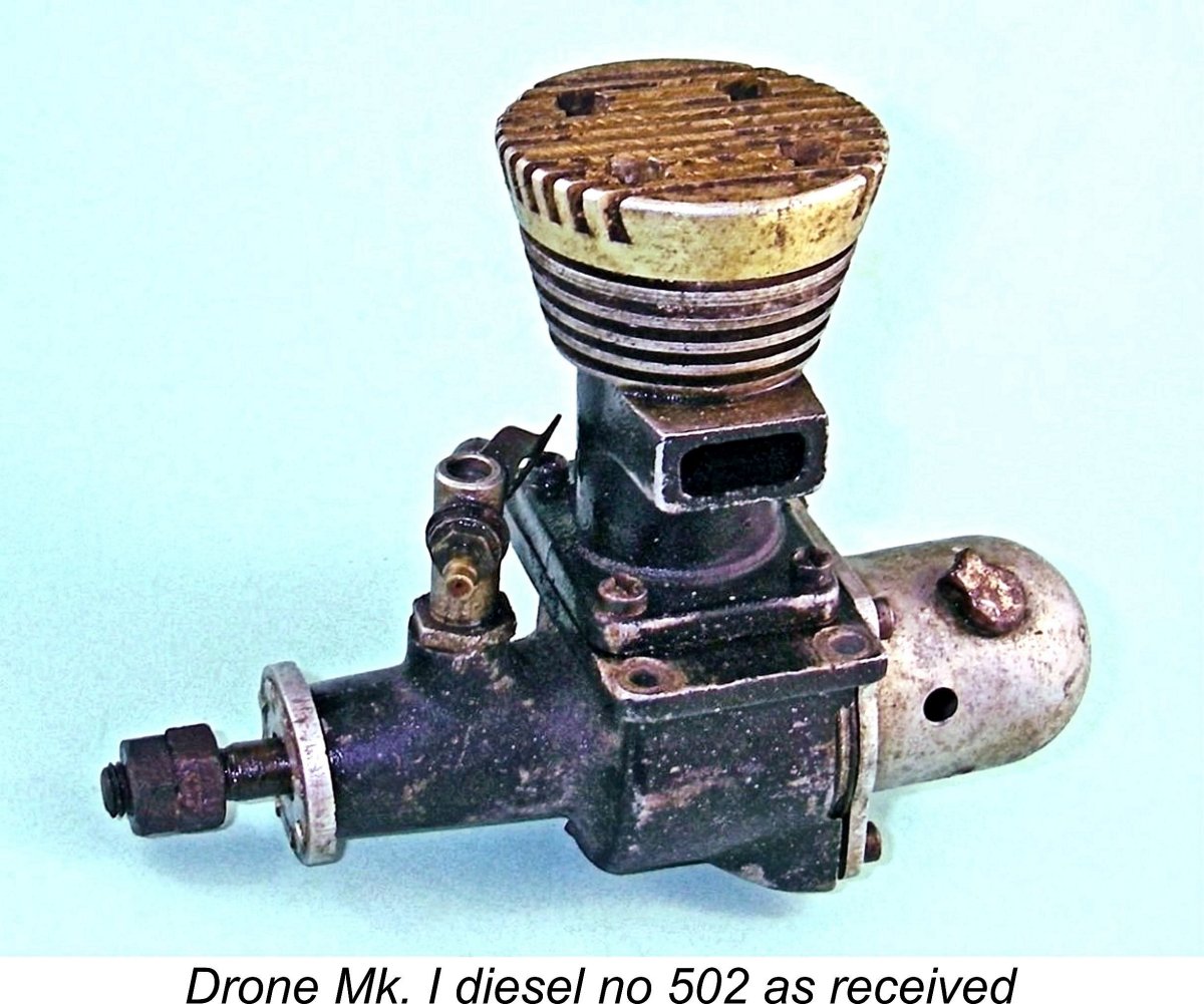
A final session in the ultrasonic cleaner using methyl hydrate had the engine ready for final re-assembly. Upon replacement of the carburettor, backplate and glow-plug (which was the Ueda original in perfect condition), the engine felt absolutely superb, turning over remarkably freely with outstanding compression and no detectable play in the rod bearings. There was still a little external etching and blotching, but nothing too serious. At the first available opportunity I set the Ueda up in the test stand to give it a few runs. After the usual precautionary molybdenum disulphide injection, it started up immediately using the original Ueda glow-plug with which it arrived. The engine ran very well indeed, making its rather strident voice heard once more after 50 years in the bucket! The throttle too proved to work perfectly. Overall, the engine was now a very serviceable and quite good-looking representative of its type. Another very successful reclamation completed! Two down, one to go …….. Drone Mk. I Diesel no. 502 This engine was actually the main reason for my personal interest in this eBay offering. I've written in depth about the Drone diesels in a separate article to be found elsewhere on this website. The Drone has always been one of my all-time favourite engines.
Once liberated from beneath its layer of grime, the engine turned out to be in remarkably good external condition. I was particularly pleased to find that the cylinder head anodizing was in excellent shape under all the crud. Even the majority of the original black finish on the crankcase remained intact. The original needle valve assembly was missing, meaning that I would have to make replica items. However, that would pose no problems. The Gits cap on the top of the tank had come loose, but at least it was still there. Again, an easy fix - JB Weld to the rescue! As with the other engines in this group, the Drone was well and truly seized with hardened oil residues. It appeared that this example had been run on a castor oil-based fuel as opposed to the mineral oil-based brew which was the recommended Drone mix and which they generally prefer. The operational issues which likely resulted may well explain the fact that the engine ended up in the bucket. In this instance, this was a good thing in terms of long-term preservation! The engine was frozen with the piston near bottom dead centre and the exhaust port consequently open, which had the potentially negative effect of exposing both the cylinder and the crankcase (through the open bypass) to the surrounding environment. Expecting the worst, I removed the tank and backplate, finding that in fact the crankcase interior was in surprisingly good shape, with only minor blemishes which were easily removed. The standard oven heating treatment followed by a dose of ATF/acetone solvent soon had the engine freed up around bottom dead centre – no need to repeat the now-familiar details here. Removal of the head (which was in perfect condition) revealed that the cylinder bore was actually in pretty good shape under its layer of 50-year old well-polymerized oil. Even so, I elected to take this one apart all the way for cleaning and inspection. It was as well that I did so, because it turned out that others had been there before me, as testified by the slightly graunched Phillips heads on the assembly screws resulting from the use of poorly-matched screwdrivers. As is so often the case, when re-assembling the engine the individual involved had omitted to refit the brass end pads on the wrist pin. Thankfully he had then run the engine very little if at all before consigning it to the bucket. Although the bore showed signs of having been contacted by the pin, it was not significantly scored as a result. Thanks to my long experience of Drone diesels, I had anticipated this, hence my decision to completely dismantle the engine for inspection. The omission of these end pads allows the pin to slide back and forth in its bosses and raises the possibility of scoring of the bore. I made new end pads to set matters right. This is always an important point to check with any engine known to have end pads or retaining circlips - those essential items are missing with depressing frequency.
Using a pair of wrenches, l held the rear nut while trying to remove the front one of the pair. No go!! The ATF/acetone mixture would have to earn its keep! After an overnight soak in the solvent mixture, I tried again. Still no go – those nuts were as rust-frozen as any that I’d ever encountered! It was clearly time for more drastic measures. I heated the front nut using a small butane torch, thereafter quenching the hot component in oil. The theory is that the externally-applied heat source expands the nut faster than the internal thread, causing the components to move microscopically relative to each other and thus weakening the bond between them. A few rounds of this, and it was time for the ATF/acetone mixture once more. This time, the front nut finally began to shift, although the torque initially required was considerable. Nevertheless, a bit of effort soon had the front nut off, allowing the rather rusty male thread to be chased with a 1/4-28 UNF die back to the rear nut. Next it was time for the rear nut. I thought that this one would be fairly easy after all of my efforts, but not so. I held the shaft using the two flats for the prop driver as a purchase, but no amount of cranking on that pesky nut had any effect despite the liberal application of both heat and ATF/acetone solvent. I actually became concerned that I might end up damaging the shaft if I kept this up. So it came down to the final solution – machine the nut off! Naturally I had to do this with the shaft still in its bearing, because the nut prevented its removal from the engine thanks to the prop driver still being trapped in place by the nut. My approach was to re-install the front nut and tighten it up against the stuck nut, then add another similar nut in front of it to provide some alignment and stability. There was just enough exposed thread to permit this. I then chucked the two “free” nuts in the three-jaw chuck of my lathe, leaving the stuck nut fully exposed. The shaft now turned with the chuck, and the pesky nut ran true enough for the purpose. The still-attached crankcase remained in a stationary position while the shaft turned in the well freed-up and oiled main bearing.
The residual metal from the fomerly stuck nut was now quite easily peeled off by running a ¼-28 UNF die along the entire threaded length of the shaft. The thread was now all ready for service again, with no trace of my rather drastic nut removal operations. I was pretty happy with the way that this worked out. The crankshaft journal and crankpin were in perfect condition, as were the rod and its bearings. However, the piston proved to be a very slightly leaky fit in the bore once both components were cleaned up. I actually gained the impression that the engine had seen a fair bit of use before ending up in the bucket with the others. Both the witness marks on its mounting lugs and the scuff-marks on the crankcase sides certainly implied that it had spent some time in a model. All that was left now was to screw it all back together. Upon reassembly, the engine felt absolutely first class, with plenty of compression when well oiled. It even looked pretty good! The only remaining requirement was to make a replica needle valve assembly, but I found that the thread is a very uncommon 5-40 UNC, which I didn't have in my tap a Since I'm sure to need them again in the future, I ordered the required items from the Tap & Die Company in England, contenting myself in the interim with fitting a P.A.W. needle valve assembly which was a perfect functional match. Thus equipped, the engine was all ready to run on demand. It didn't take me long to make just such a demand by setting it up in the test stand with the P.A.W. needle valve still installed. I fitted it with an 11x7 wood prop and used my standard Drone Mk. 1 fuel mixture of 70% ether and 30% SAE 30 mineral oil. As stated earlier, the compression seal was very slightly "soft", which these engines don't tolerate well because you can't increase compression to compensate. However, a few drops of oil in the exhaust sealed things nicely. Once this was done, the engine started up just fine and swung the 11x7 prop with great authority - the compression seal was clearly more than adequate for running purposes. Another Drone rescued from the dumpster and restored to useful condition – I’m all for that! So in the end I got three fully serviceable and quite good looking engines for my $80 investment, including a nice example of one of my personal favourites. Pretty good value for money in my book! A Hope “B” restoration
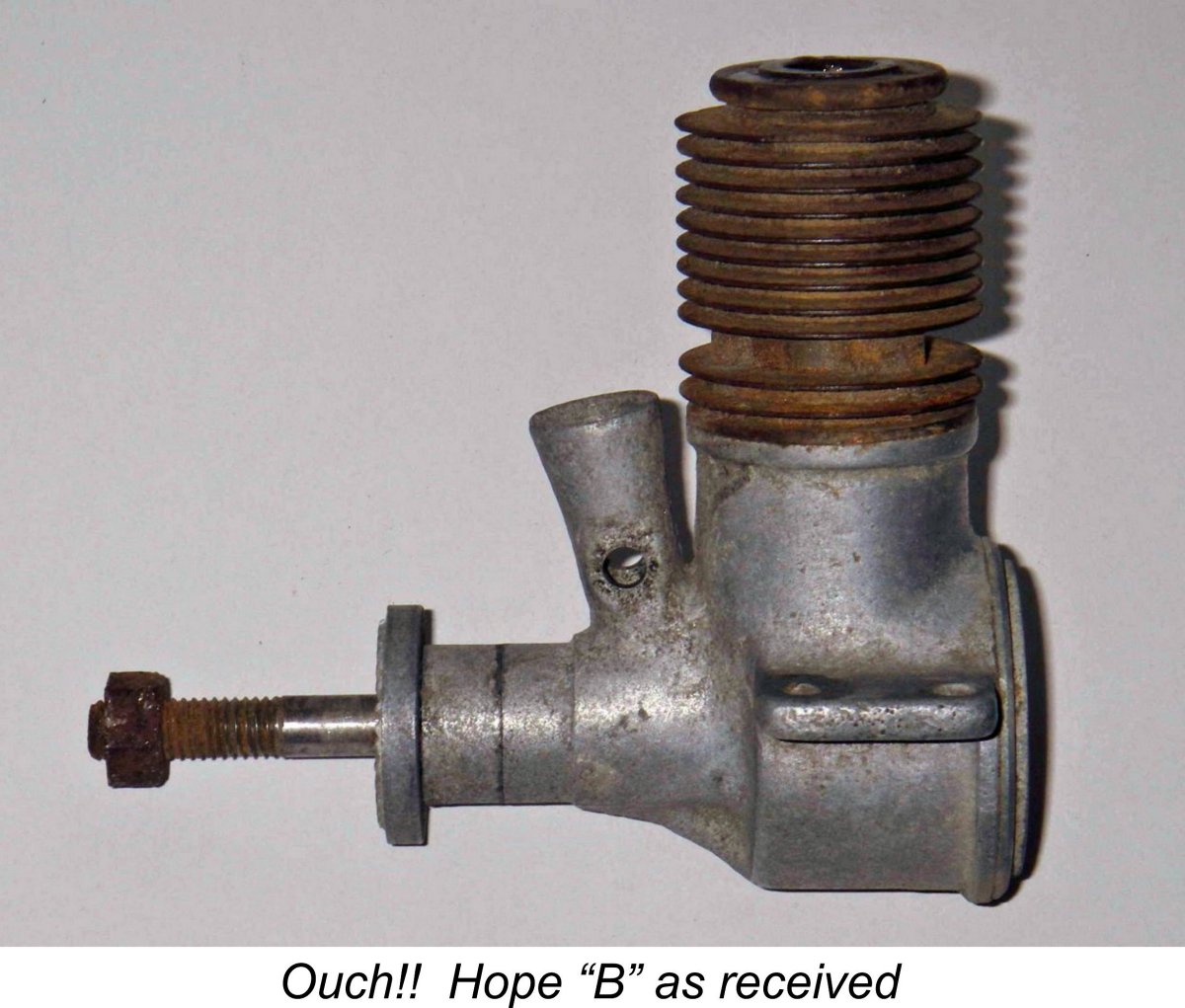
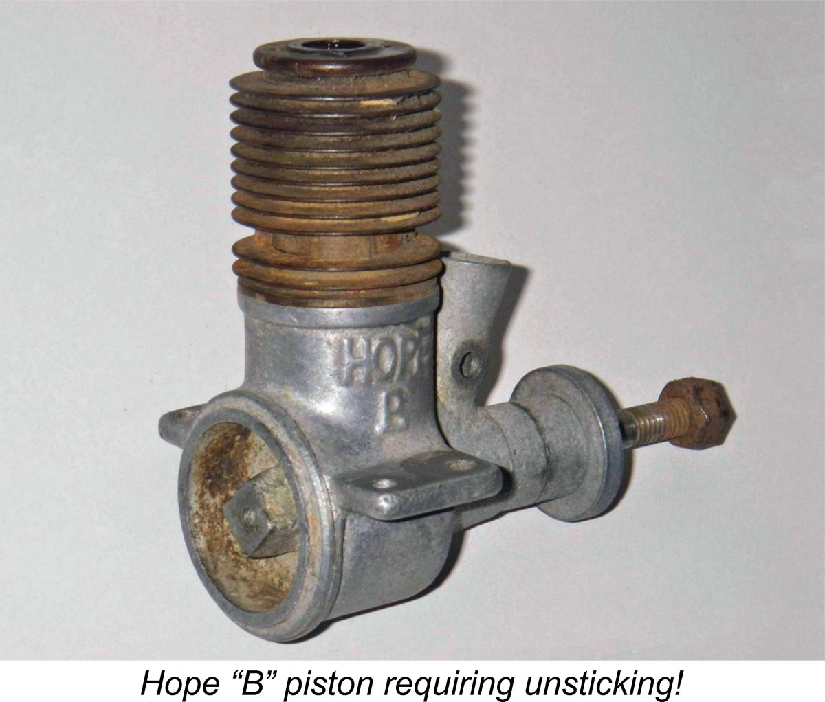
Saving the best for last, we now turn the clock all the way back to 2009 to have a look at what I still consider to be my finest and most instructive restoration effort from an extremely unpromising beginning. During March of 2009 I bid on an old 1948 Japanese Hope “B” .29 cuin. glow-plug engine which appeared on eBay. The motor was obviously in pretty rough shape, but it had the attraction of being set up for a 3/8 in. plug, making it a relatively rare early example of the Hope "B" glow-plug model. It was missing a lot of bits, but those that were there appeared more or less intact apart from some glaringly obvious corrosion and the mandatory chip out of the top cylinder fin. No Hope "B" is complete without one! At the time, I was just getting started on the major Hope research project, the results of which remain accessible on the late Ron Chernich’s ever-engaging “Model Engine News” (MEN) website. Consequently, I already knew these engines pretty well. This being the case, I thought that I'd have as good a chance as anyone of restoring it or at least salvaging some useful components. I knew that I could make accurate repro components using examples already in my possession as a guide. So I went ahead and joined in the fun! And fun it was ............despite the engine's corroded and incomplete state, its relative rarity resulted in the When the engine arrived, it became instantly and uncomfortably clear that my investment stood on somewhat shaky ground! If anything, its condition was worse than I had expected, and my first reaction was that I might have taken a financial bath! However, I'd made the investment and was stuck with the results - best to see what could be done to salvage the situation....... As always, the first thing to do was to assess the challenge, taking plenty of time to do so. This is undoubtedly the most important step in any restoration - far too many restorable engines have been further degraded through ill-considered attempts to dismantle them before the problems involved were fully appreciated and the appropriate steps fully thought through. As received, the thing was basically a lump of rust, and my initial examination led me to the preliminary conclusion that the best I could realistically hope for was to save the case, shaft, prop driver, backplate and cylinder. I fully expected to have to make a new piston and rod as well as replace the entire fuel system (which was missing altogether). I always start from the premise that the underlying approach must be to save as much of what's there as possible. This means avoiding any steps which will inevitably lead to the irreparable damage of any component unless every alternative has been tried or at least considered. In many cases it also dictates the order in which steps have to be taken. Inevitably, there are times when you have no choice other than to "sacrifice" a component, but that should always be a last resort.
It was immediately clear that if the piston proved to be irreversibly "welded" into the bore by corrosion, the only way forward would be to sacrifice the rod by unscrewing the cylinder using a combination of heat, solvent and brute force, accepting the inevitable twisting and breakage of the rod. But before trying that, it was obvious that every effort should be made to un-stick the piston in situ. I honestly didn't expect to succeed, but the right thing to do was give it a go regardless. The next step was once again to see how the parts were aligned in the engine's frozen-up state. All that external examination revealed was that both the exhaust and crankshaft induction ports were closed. To learn more, it was necessary to remove the screw-in backplate, which was well and truly gummed in there. There were no peripheral slots with which a flat metal key could engage, nor was there sufficient material to allow the backplate rim to be held sufficiently firmly in a lathe chuck. However, the designer had provided for backplate removal by including an integrally-cast square-sectioned boss of material in the centre of the backplate. The intent was clearly that a square-sectioned socket wrench driver would engage with this boss to remove and re-tighten the backplate. Thankfully, I just happened to have a socket set which included a driver which fitted the backplate's central boss perfectly! Having established this fortunate fact, I then heated the whole engine in the oven to soften the castor oil residues that were effectively gluing things together. Even then, it was tough and required both nerve and persistence, but the backplate finally came out after several attempts. You have to be patient and above all use the right tools. No vice grips, please - they would have wrecked this particular component. Removal of the backplate revealed the con-rod and crankweb, which were far less corroded than I'd been expecting. The engine had obviously been run on a fuel containing castor oil and had been put away without being flushed out. As a result, all the internal surfaces were covered with a congealed castor oil film. Castor oil is a great rust inhibitor, and its presence had largely inhibited the development of internal rust. Too bad about the exterior ..........!
I was mildly encouraged by this finding. However, I found that the shaft was also frozen in its bearing, since it would not move axially at all. Both piston and shaft would therefore have to be unstuck if the dismantling process was to succeed. The application of brute force was not an option, since it would almost certainly result in damage. It would be necessary to proceed very carefully in stages. Setting that challenge aside for the moment (yes, I'm a talented procrastinator!), the next task was to see what lay underneath all of that external surface rust. This required the removal of all externally visible traces of rust using a soft brass-wire brush along with an appropriate penetrating lubricant having good rust solvent qualities. The most effective such substance is the afore-mentioned blend of automatic transmission fluid (ATF) and acetone, but on this occasion I used Liquid Wrench, which is one of the best commercial products. This was sufficiently effective that I felt no need to resort to the use of naval jelly.
The only way to free the piston in the bore would clearly be to shift it downwards along the bore axis – trying to get it to rotate in the bore in its present location while unscrewing the cylinder would inevitably twist the rod. However, in order to shift the piston axially while still connected to the shaft by the rod, it would be necessary to free both the shaft and rod bearings to permit them to rotate as the piston moved downwards. It was thus obvious that in order to make any progress from this point I would first have to loosen the shaft in its bearing. Until that happened, the piston was going nowhere. To accomplish this, I soaked the engine overnight in solvent, gave it a shaking in the ultrasonic cleaner, heated the engine up in the oven, injected more Liquid Wrench (very much including the rod bearings, which also had to be free to turn) and then tried very gently tapping the shaft both radially (using a crescent wrench on the prop driver square) and axially in both directions using a very light pin hammer and watching for movement. I wasn’t looking for any significant rearward movement, since that would bend the rod – rather, I was merely looking for some very slight indication that the shaft was free to move axially in its bearing. After another heating session and some more gentle persuasion while hot, the shaft finally displayed a little movement - as much as the rod and the stuck piston would permit - and the Liquid Wrench capillaried into the bearing. Although not yet completely cleaned up, the shaft now exhibited some axial movement and was therefore presumably free to turn - the castor gum bond was broken. OK, on to the next task – shift the piston! I put the engine through a further long sequence of heat cycles, applying more Liquid Wrench when hot each time both to the upper cylinder (through the plug hole) and through the exhaust and transfer ports and allowing complete cooling between heating sessions. This was tedious in the extreme since the preservation of domestic harmony required me to soak the engine in methyl hydrate to thoroughly remove all traces of Liquid Wrench before each session in the oven. That stuff does have an aroma to it ...........
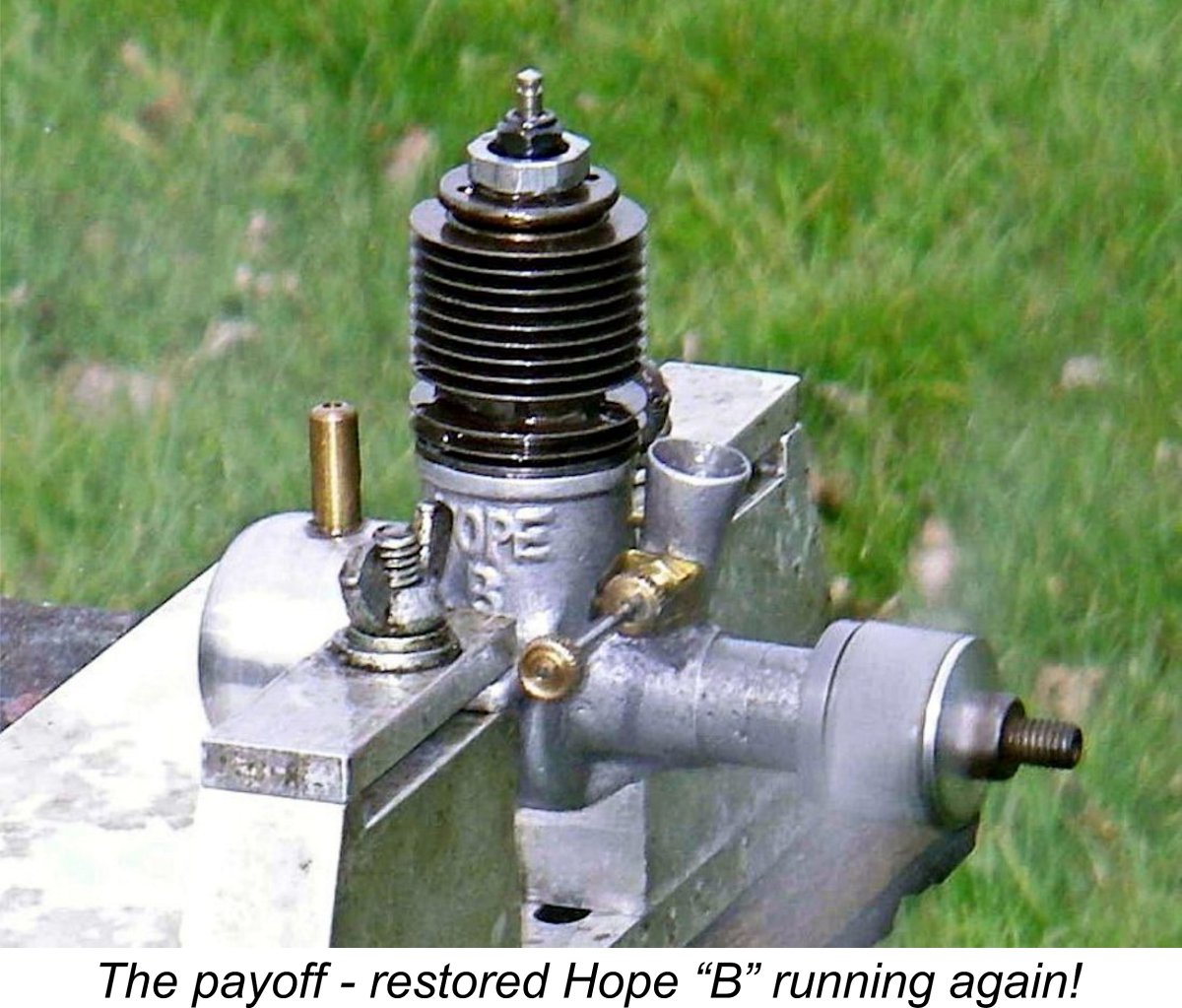
After that, it was easy - I just warmed the engine up once more, lubricated the hell out of the whole assembly (including the shaft and rod bearings) with Liquid Wrench and then screwed the bolt down to push the piston smoothly down to BDC, at which location it felt almost completely free. Since I had already freed the rod and shaft, this procedure did no damage - the shaft just turned as the piston came down. Then came another heat cycle with the piston at BDC followed by a little rocking of the shaft back and forth around BDC to ensure that the piston was indeed completely free. Having established this beyond doubt, the use of a matching pin spanner (no vice-grips, please!) using the holes provided in the top cylinder flange persuaded the cylinder to unscrew while hot with little trouble and no damage to the rod. All of this had of course taken some time, but now came the payoff!! The rod and shaft proved to be in perfect condition. All the working surfaces turned out to be in excellent shape apart from the very top of the bore and the areas of the piston skirt which had been open to the exhaust ports. As mentioned previously, the thing had stuck very near TDC so the slightly etched areas of the piston which had been exposed in the exhaust ports were near the bottom of the skirt where such issues matter less in any case. The short working length of the bore above the point where the piston crown had stuck was a bit rusty and also had a bunch of sand glued in it - you can see some of that in the above "un-restored" top view! But the plug installation thread was still servicable once the rust and sand had been removed, while the rest of the bore was A bit of steel wool with Liquid Wrench soon had all of the residual rust out of the upper bore and off the piston walls. I cleaned the parts ultrasonically and did a quick test re-assembly. Oh joy!! The thing turned over very nicely and the compression was outstanding! No need for a rebore!! The excellent condition of the rod, gudgeon pin and shaft implied that the engine had been little used before being abandoned to its fate. The castings were close to mint. Using plenty of Liquid Wrench, I "ran" it for 5 minutes on the lathe without a plug, after which it felt superb. I then dismantled the engine again for a final cleaning prior to re-assembly. Once that was done, it was a simple if somewhat time-consuming matter of making an accurate replica fuel system and prop washer, installing an antique Champion glow-plug and there it was! Frankly, I would not have believed that an example this nice could have been created from the unpromising "remains" of the old Hope "B" as received! All it took was time ..... lots of it.......and a matching amount of care!! A subsequent test session (using a ¼ in. plug adaptor to conserve the Champion plug) proved that the old Hope started and ran as well as it looked! Click here for a video clip of the engine running. Conclusion The moral of the above stories, particularly the last one, is - never dismiss an engine as un-restorable until all possibilities have been fully considered. Once you decide to go for a restoration, never give up until all avenues have been exhausted. Spend some time up front deciding what can potentially be saved, and then set methodically about saving it, using the appropriate tools and methods throughout. During the restoration process, always keep looking for opportunities to save more. Given a well focused slow 'n steady approach, you may sometimes be surprised at just what can be accomplished, as I certainly was with that rusty old Hope “B”! The guiding philosophy must always be to tackle the various tasks in a logical sequence, taking your time and always using the right tools and methods. We lose far too many fine old engines to over-hasty attempts to sort them out using the wrong techniques or inappropriate tools. Take your time, and it's amazing what can be saved! __________________________________ Article © Adrian C. Duncan, Coquitlam, British Columbia, Canada First published December 2018 |
 From time to time most model engine enthusiasts run into an opportunity to acquire an interesting or unusual old engine that is well and truly rusted up and seized solid as a result of being stored for years in damp conditions with old castor oil residues gumming up the works and a good layer of rust and grime covering everything else. Back then, people didn’t realise that their old unwanted engine would one day be a collectible!
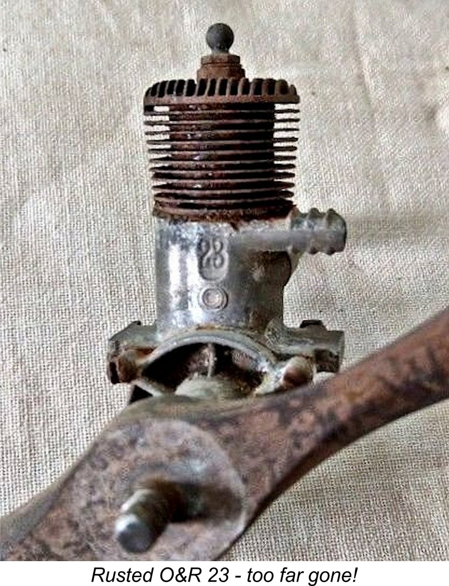
 A collection of the appropriate tools that will be required. This is probably both the most important and most frequently overlooked requirement. More potentially restorable old engines become further degraded through the use of the incorrect tools than from any other cause. Vice grips and pliers are the worst offenders, but they’re by no means the only ones – incorrectly-sized wrenches (or poorly-adjusted crescent wrenches) and poorly-matched screwdrivers are also high on the list. When dismantling such engines for restoration, please use the proper tools!
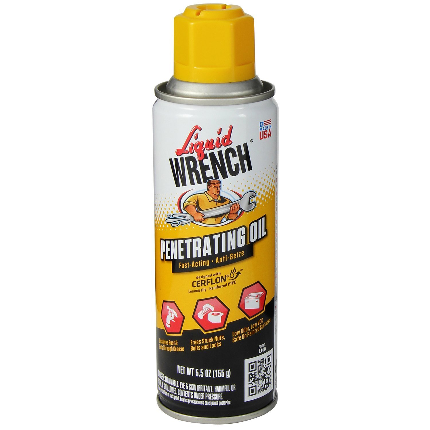 A supply of an appropriate penetrating rust-removal agent.
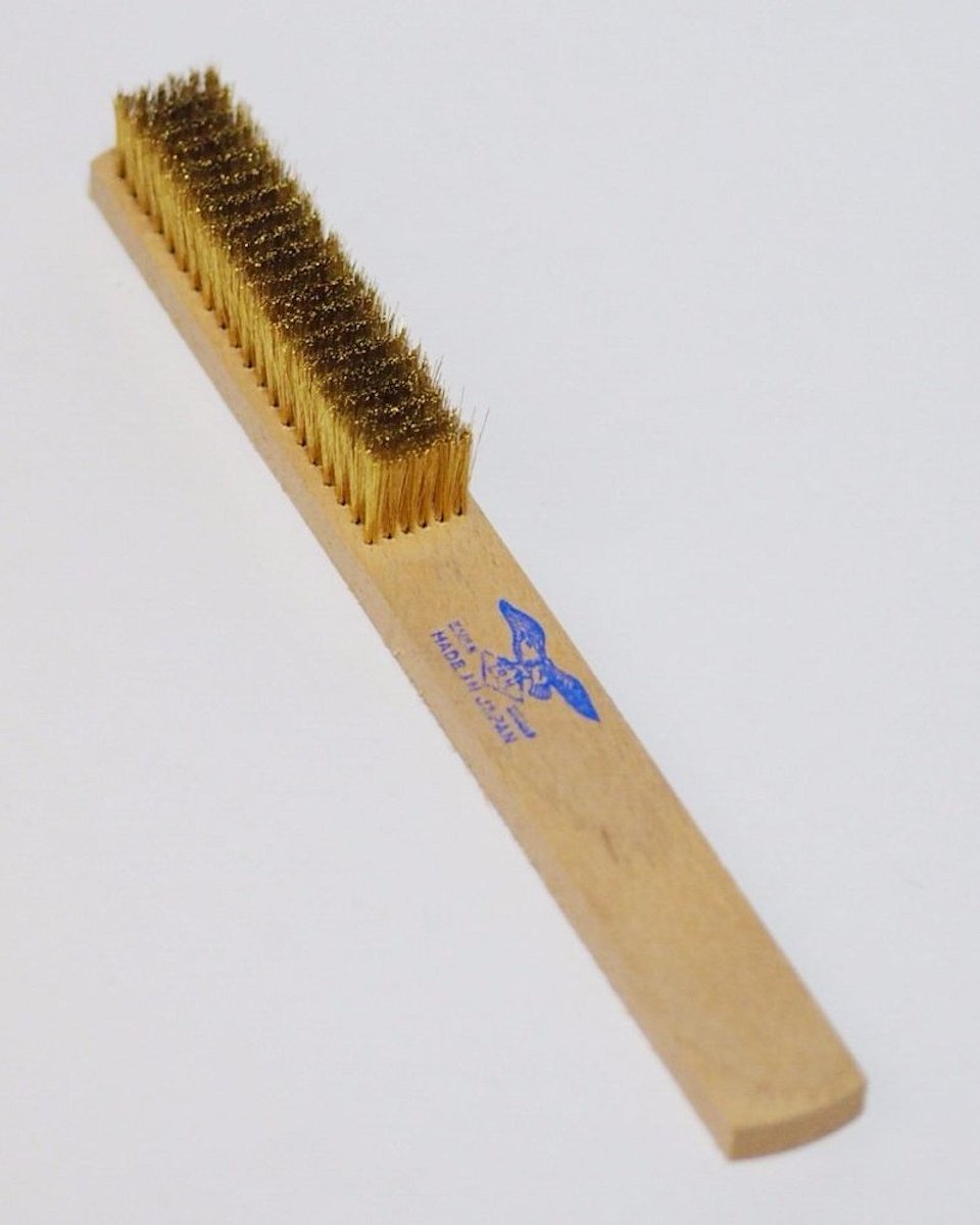 Some steel wool and a soft brass wire brush - the kind used for cleaning jewellery is good. An old toothbrush is also useful at times, as is a larger brush having soft nylon bristles. Do not use any kind of abrasive paper or hard-wire brush, both of which will change the surface finish of light alloy components very noticeably. Also, please resist the urge to polish components that weren’t originally polished – I’ve spent countless hours restoring the original patina on components which have been “prettied up” by misguided former owners, ending up looking nothing like the originals and hence eroding the value of the engine.
 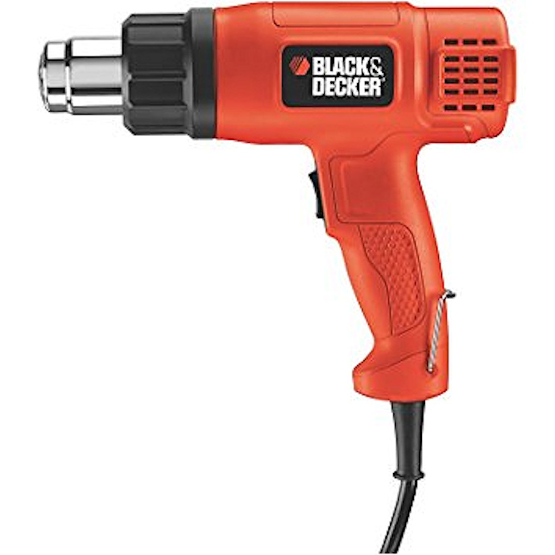 A variety of heat sources along with some heat-resistant gloves (old oven mitts are great) for handling hot components. Castor oil gum softens considerably with heat, so this is a very effective technique for shifting gummed-up components once the rust is removed to the extent possible. A small hand-held butane torch is very useful at times, although it can become a fire hazard if improperly handled. Best used outdoors. A high-power heat gun can prove quite helpful as well, also posing far less of a fire hazard. A domestic oven is indespensable for situations in which the entire engine has to be heated.
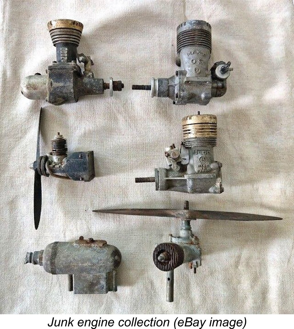 In June 2018 I bid on a group of rusted and well-stained engines which were being sold “as is” by a very honest seller. He openly characterized the collection as “All junk.....this lot is offered for parts or repair only......all are non-working, locked up, pitted out, rusted up, crusted up, dusted up, seized up, dirty junk in the worst condition you can imagine”.
 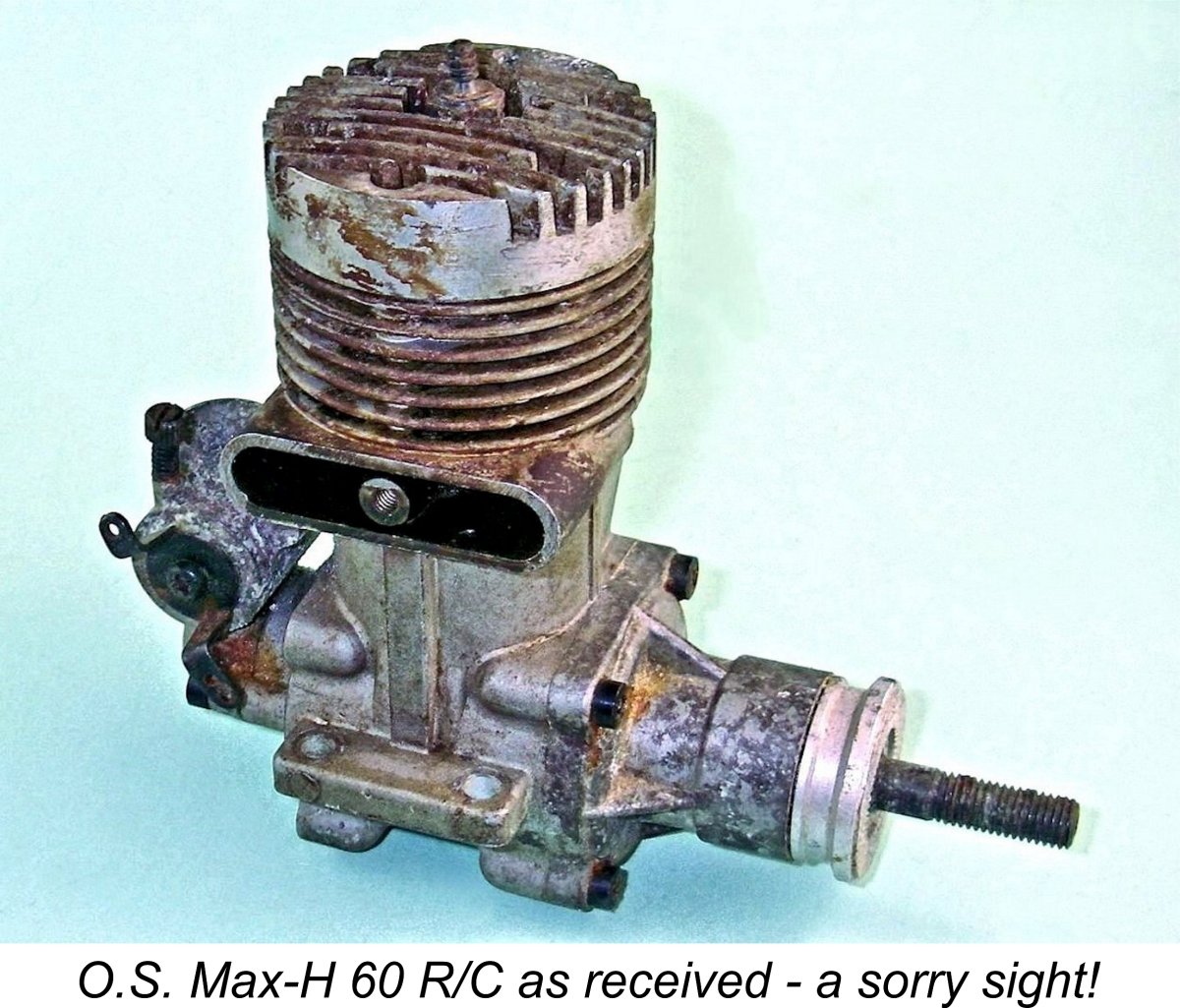 This engine is a 1966 rear drum valve model. It's a technically interesting design featuring a down-draft intake, an inside-out (or centrifugal) drum valve, a twin ball-race crankshaft and a two-ring aluminium alloy piston. The Max-H 60 R/C was recognized in its day as a fine-handling general-purpose powerplant with a good power output by the standards of the time. Peter Chinn found a peak output of 0.96 BHP @ 12,800 RPM in his
 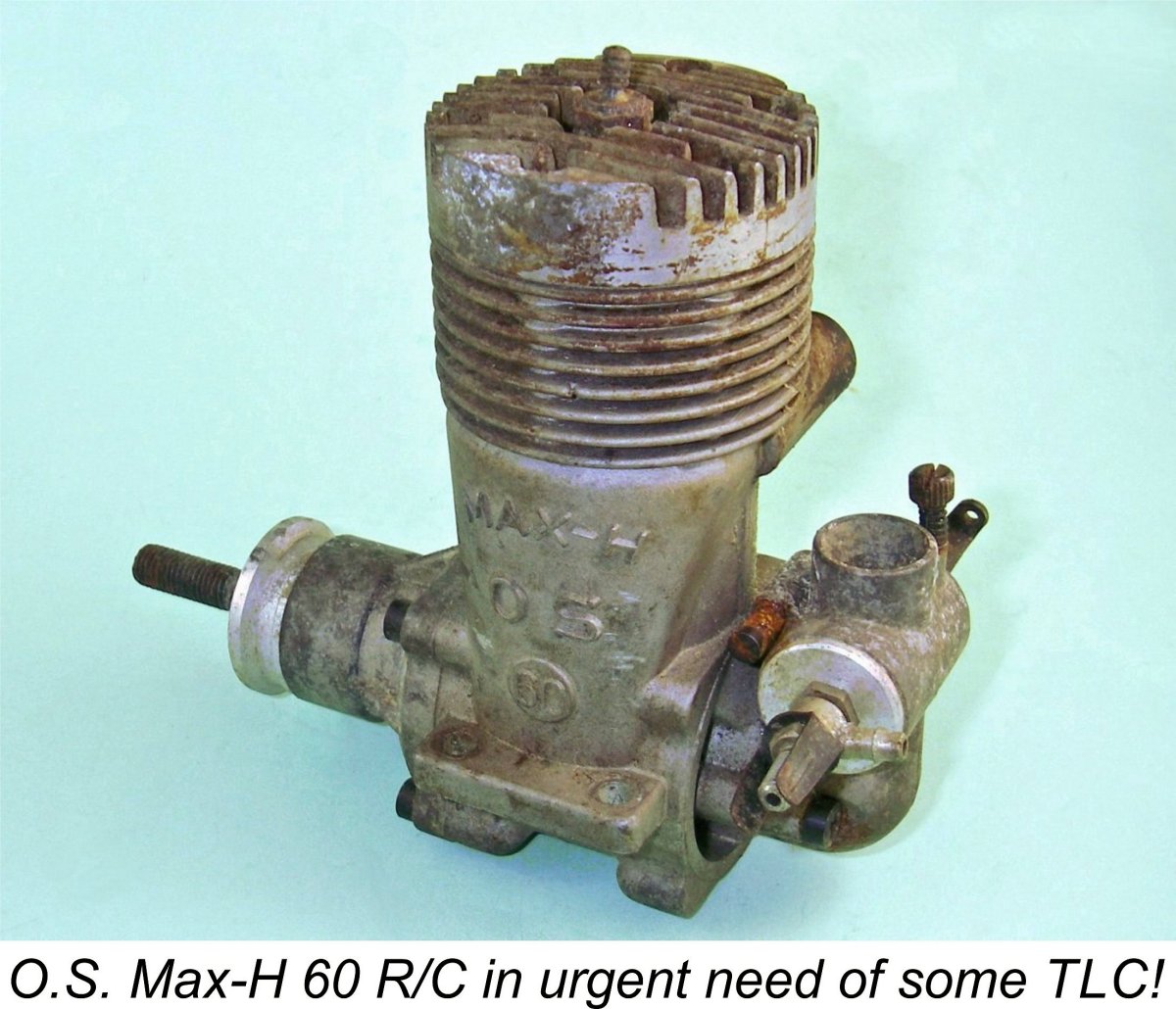 Apart from the inevitable layer of grime and castor gum which covered everything, the engine showed clear external evidence of water damage in areas which had not been covered by the castor residues. Rust was evident on a few of the ferrous components - check out the air bleed screw in the accompanying image. Most of this was fairly superficial and would come good with the liberal use of rust-removal solvents and brushes. The water-induced mottling of the crankcase material would be impossible to remove completely, but it really wasn't too bad under all the grime.
 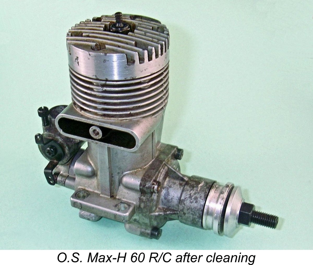 Then came some more soaking in methyl hydrate, making sure that plenty got down through the bypass to the crankcase to work on the rod and shaft bearings. Periodically I removed the engine from its bath and rocked it back and forth over bottom dead centre. This was done to ensure that the conrod bearings were completely free to turn on their respective pins. At this stage, I refrained from turning the engine over all the way because the condition of the main bearings was still unknown.
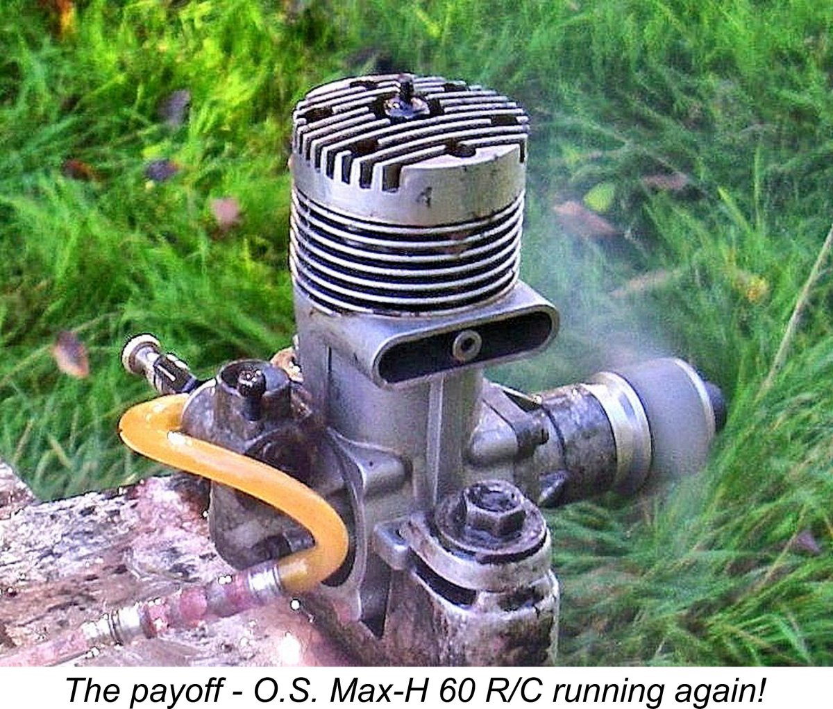
 So much for the external assessment. As is usually the case, the next thing to do was to unstick the piston and get the engine turning. Until that was done, nothing could be accomplished by way of dismantling. Since this engine does not have a removable main bearing housing and the piston was obviously frozen fairly close to top dead centre, it would be necessary to get the piston freed up along its entire stroke before considering any further actions.
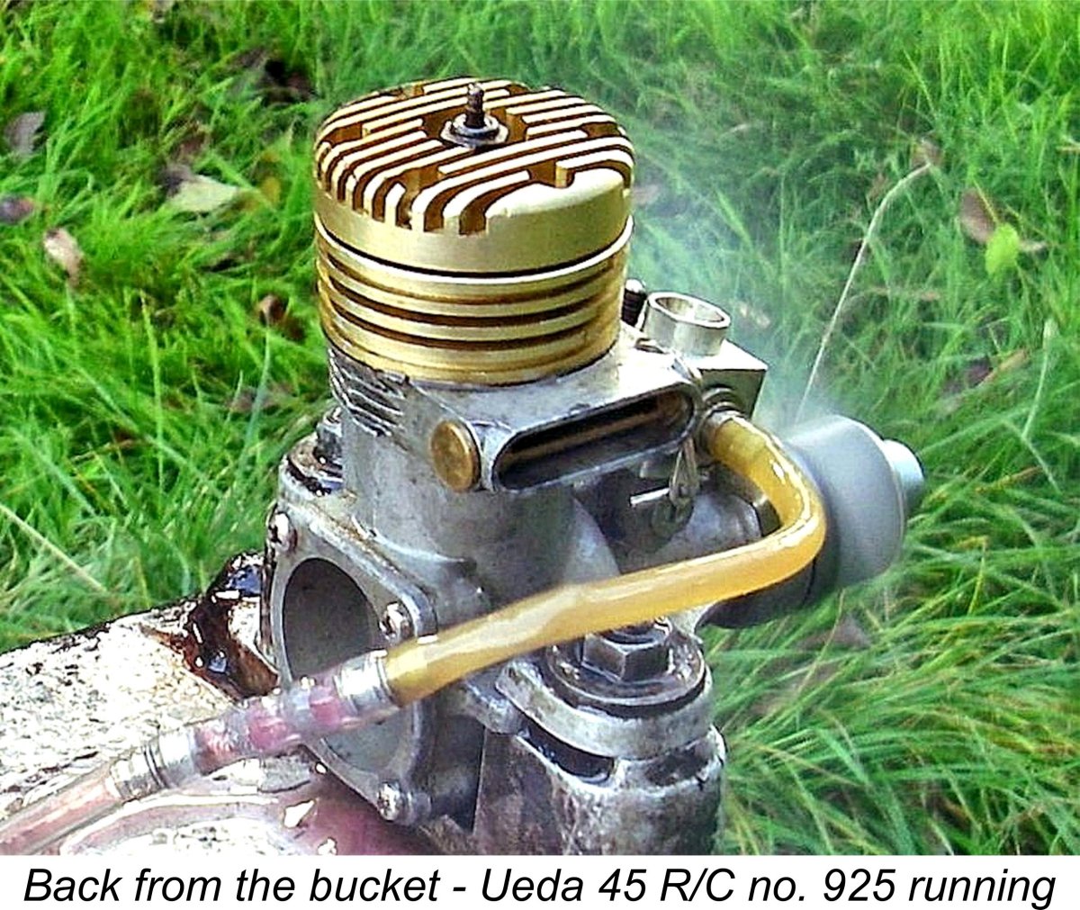
 This example appeared to be almost complete under all the grunge. Based upon its low serial number, it was a very early example of the Mk. I Drone, dating from 1947 (the year in which I was born!). If I could restore it to reasonable condition, that alone would more than justify my $80 investment!
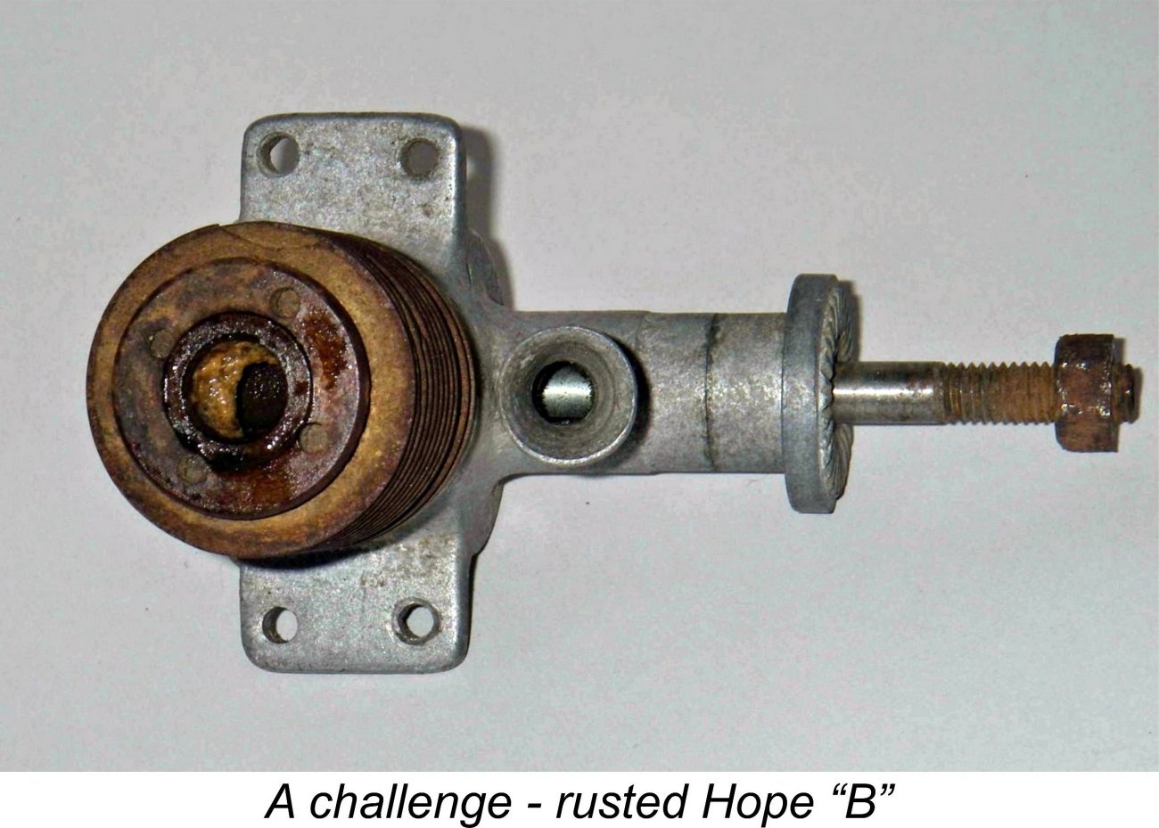
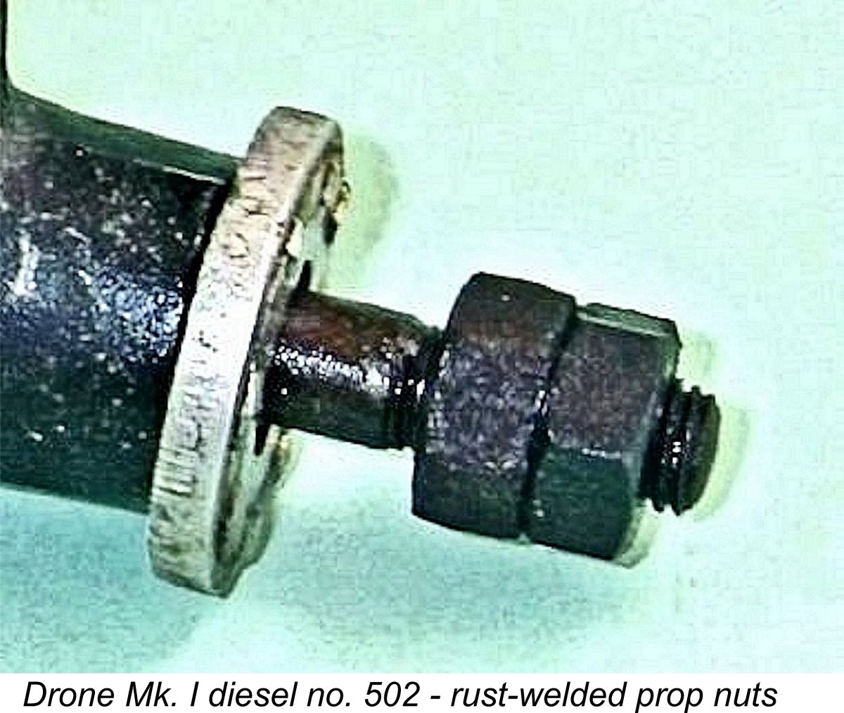 In this instance, the worst rust damage was at the front of the crankshaft. The engine had evidently spent its time in the bucket in a downward vertical orientation with its prop mounting thread and twin nuts immersed in some accumulated water. There were two prop nuts, and both of them were well and truly welded on by rust.
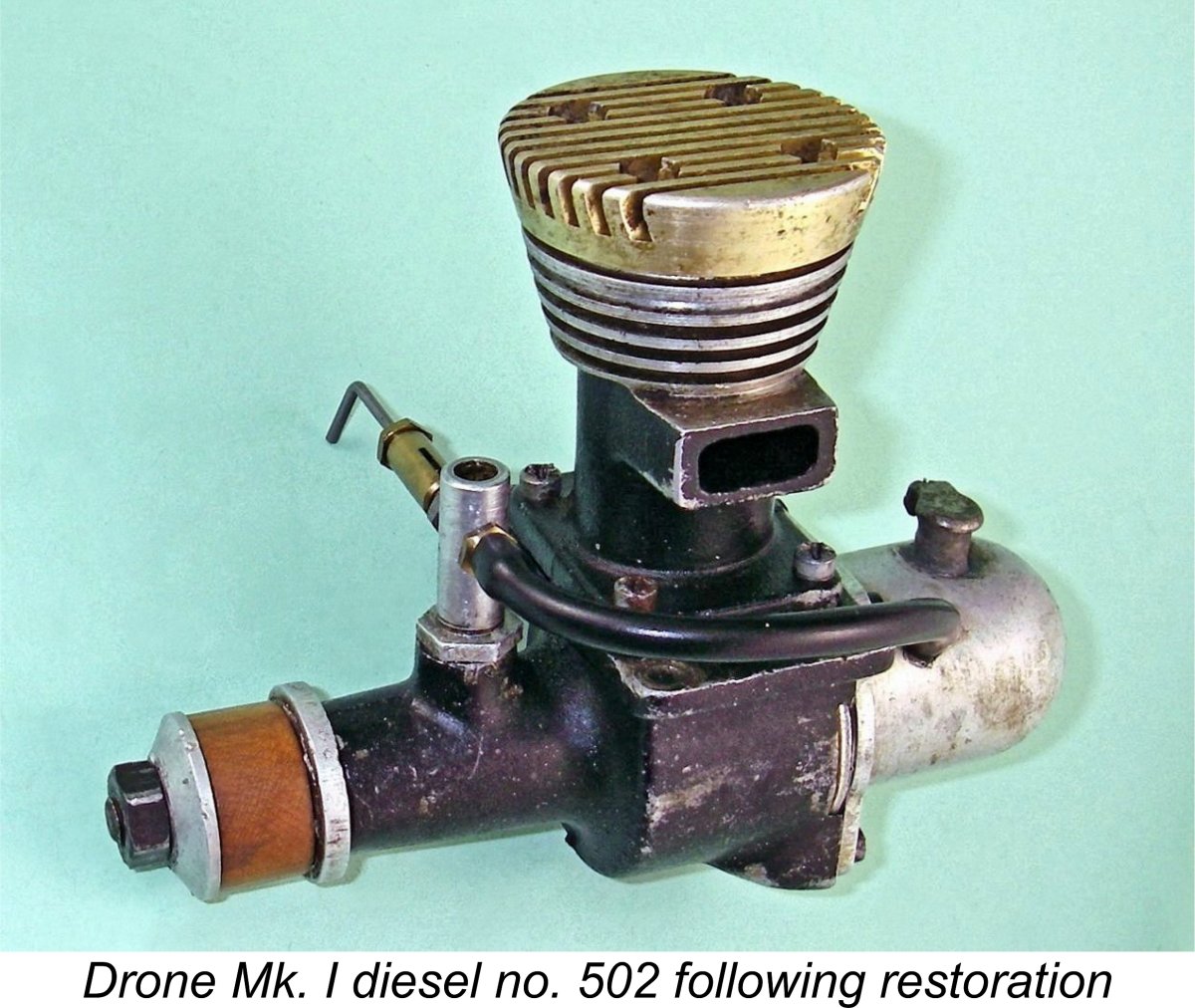 I established the top slide setting at which the cutting tool was just at the point of contacting the visible threads on the crankshaft, and then proceeded to machine away that dratted nut down to the established near-contact setting. At the end, I was left more or less with only a spiral strip of metal embedded in the prop shaft threads where the rusty nut had been. Once the two chucking nuts were removed, the prop driver was released and the shaft could finally be removed from its bearing.
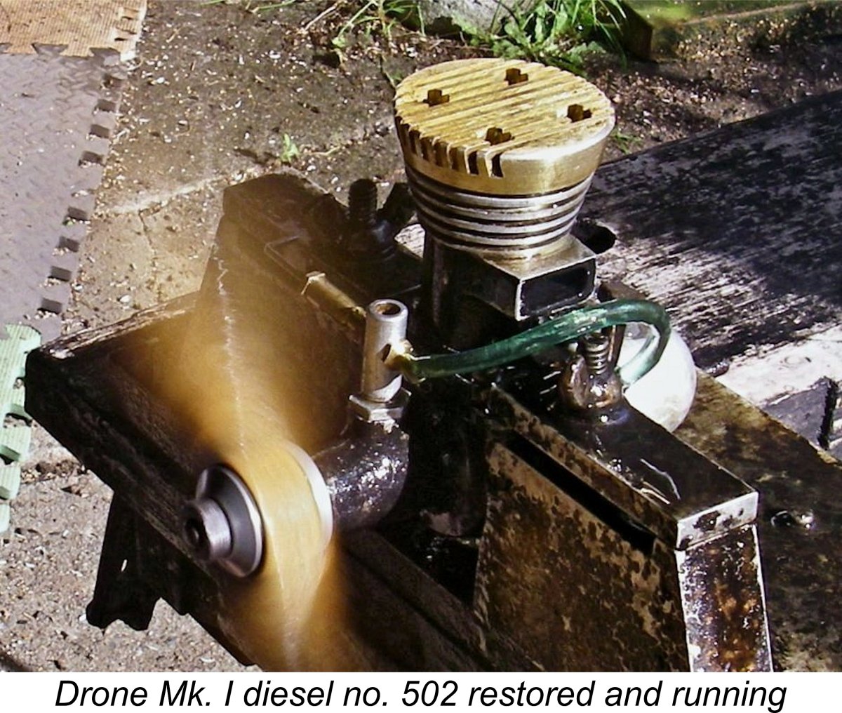
 A classic case in point relates to the preservation of the conrod in engines like this one having a screw-in cylinder. On engines which are assembled in this manner, the first imperative must be to get the piston unstuck and able to turn freely in the bore so that the cylinder can be unscrewed without twisting the rod. On this rusted-up example, that looked a bit problematic!
 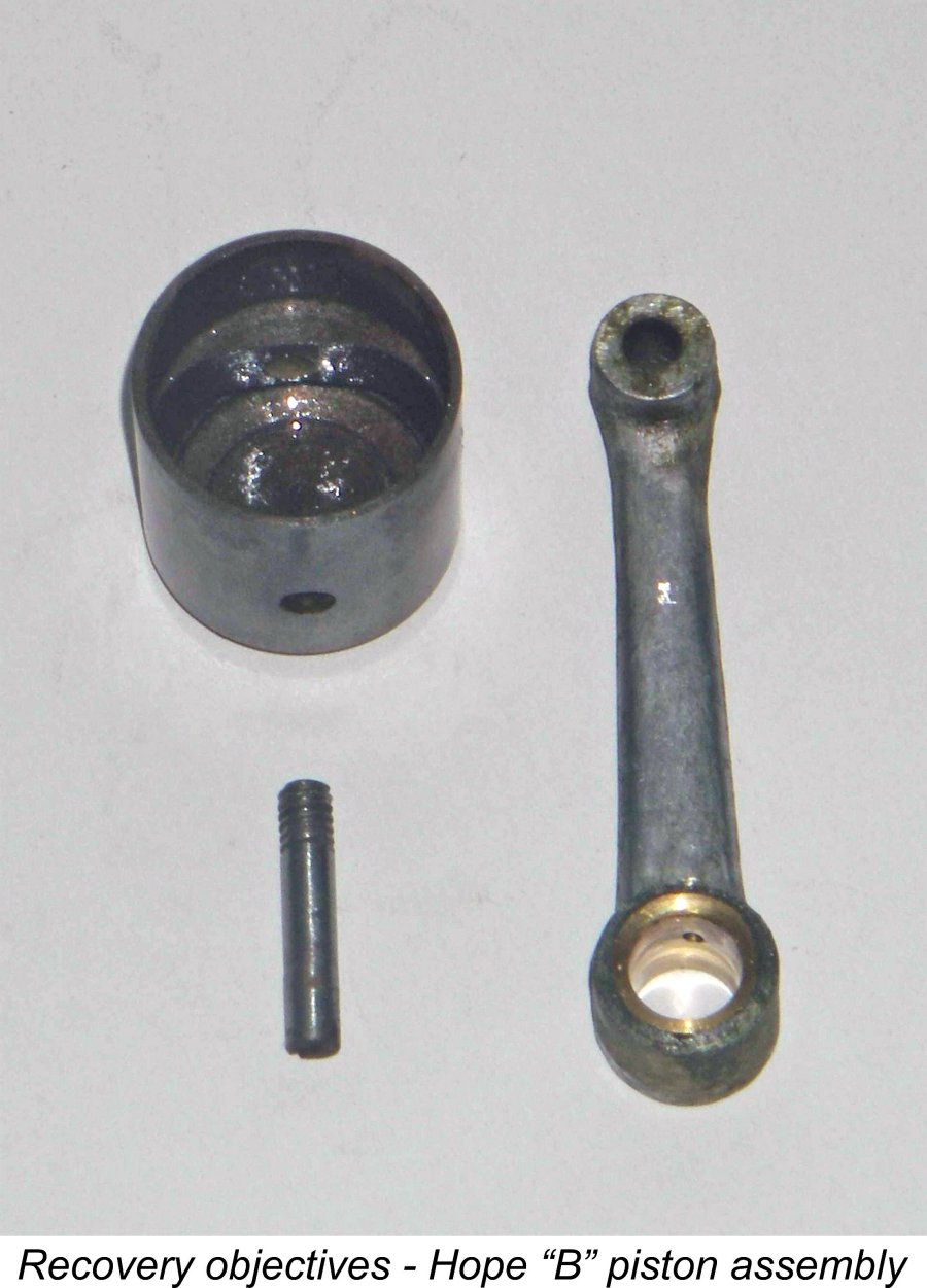 The engine proved to have been frozen at about 20 degrees past top dead centre, just after the closure of the crankshaft induction port. From a preservation standpoint, this was probably the most favourable position in which it could have become frozen, since the crankcase interior had been isolated from the external environment by virtue of both exhaust and induction ports being closed. The fact that no plug was fitted had left the upper cylinder exposed to corrosion from external sources, but the fact that the piston was frozen near top dead centre meant that only a relatively short length of the working bore was left exposed. Moreover, it was a reasonable expectation that residual castor oil gum might have protected much of the bore and piston working surfaces under all that external rust.
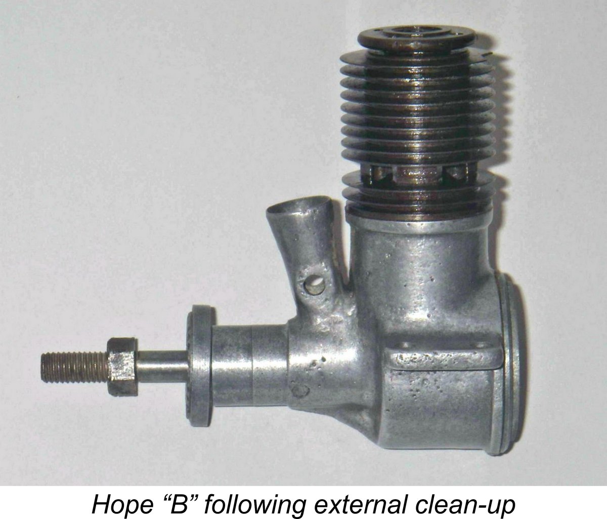

| |