
|
|
An Undocumented Ten-Sixty-Six 2.75 cc Diesel Prototype?!? The extremely well-made and technically unusual 2.75 cc sideport diesel which I’ll be describing and testing was acquired on eBay in 2018 from an English seller named Freddy Webb, the son of Steve Webb of Steve Webb Models. Steve told me that he had acquired the engine a few years ago from a formerly well-known aeromodeller named Brian Rowe who used to work with his friend Jim Dyson designing and testing flying model designs for Ben Buckle. Perhaps their best-known design was the 78 inch wingspan Super Elf Biplane. At the time of its acquisition by Steve Webb, the diesel in question was accompanied by a larger but basically similar-looking model featuring spark ignition. That unit was damaged and very much incomplete. It was passed along to a well-known dealer some time ago. If our tentative identification is correct, it was probably an example of a member of the Ten-Sixty-Six 5 cc sparker series, most likely a Falcon. Having looked at a few images which I supplied, Steve now believes from memory that this interpretation is indeed correct. Steve had given the 2.75 cc diesel to his son Freddy to sell (to help pay for driving lessons!). During the course of the eBay auction, neither the Webbs nor I had any idea what this engine might be. However, it was quite obvious that someone out there could have identified it for us if he had chosen to do so! The seller got the very strong feeling from inquiries received that several bidders (including a couple of dealers) knew what it was and saw it as something special but weren’t saying, perhaps hoping to keep the level of interest and the consequent selling price down. Of course, the unusual attention being paid to what appeared at first glance to be a one-off "special" by an unknown maker had the opposite effect - I read the signs and decided to take another of my “gut feeling” eBay fliers, going fairly high to get this one. I was motivated both by the engine’s readily apparent features of technical interest and the fact that others who were perhaps more knowledgeable than I clearly saw it as having a high intrinsic value.
If it wasn’t for the above shenanigans, I would probably have been prepared to believe that this was more likely than not to be the work of some very talented model engineer. As it was, and particularly after examining the engine in person, I became more than ever inclined to believe that whatever it was, the engine had a pedigree of some kind. The British threads used throughout pretty much confirmed a British origin. The use of no fewer than four separate high-quality die-castings of considerable complexity (crankcase, main bearing housing, cylinder jacket and exhaust stack) would be highly unusual for a non-commercial British one-off home build. Someone went to a lot of trouble and expense to produce those four dies, implying an expectation that the engine might be produced in series or at least offered as a kit. Didn't suggest a home-builder to me! And then there were the clear indications that more than one person knew something, which meant that there was something to be known……………. Feeling sure that this engine was the previously-unattributed work of some "name" British maker, I shopped images around among my extensive circle of knowlegeable model engine aficionados. Although no-one could positively identify the engine (a highly unusual circumstance given the knowledge base into which I was tapping), there were a few suggestions – perhaps an undocumented experimental model by someone like J. Hallam, Edward Reeves or Henri Baigent (B.M.P.). There was also a suggestion that this might be an experiment by Edgar T. Westbury – the general layout, cylinder head style and I-section con-rod are all typical of his work.
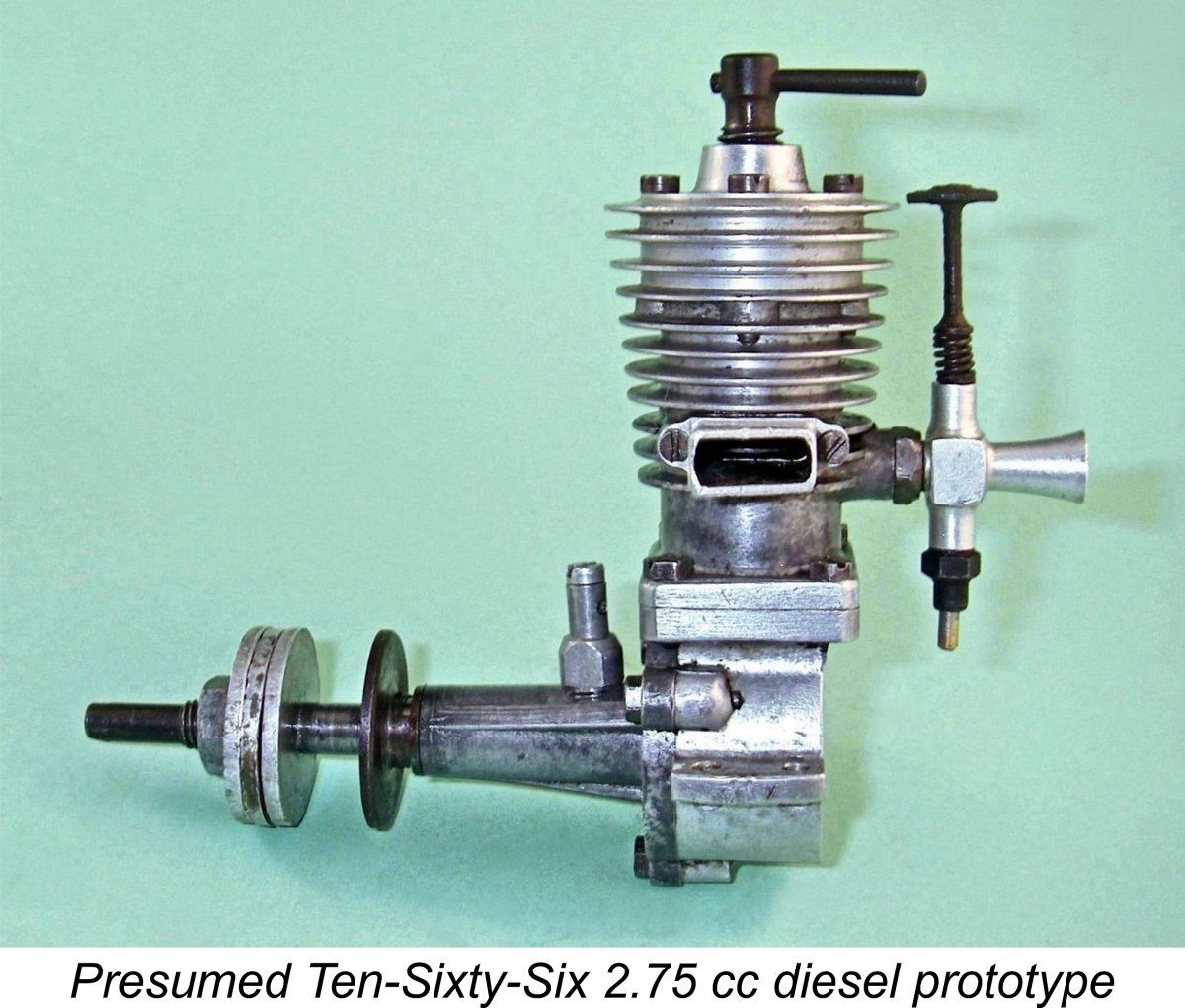
Perhaps the most indicative of these features is the very unusual configuration of the front end of the crankshaft, an arrangement unique to Ten-Sixty-Six as far as I'm aware. Moreover, Ten-Sixty-Six founder Geoffrey I. Hastings is known to have been a friend and associate of Edgar Westbury, which would amply explain the engine's seeming Westbury influence. Quite apart from this, Hugh Blowers (my friend and guru on all things related to Ten-Sixty-Six) has advised that during the run-up to the 1947 “Model Engineering Exhibition”, rumours circulated that a diesel would be among the products to appear on the Ten-Sixty-Six stand. However, such a unit failed to materialize at the Exhibition. Although I can’t prove it, there’s a strong possibility that this engine was a prototype of the rumoured diesel model. It's largely on the basis of the above observations that I've provisionally identified this engine as a 2.75 cc diesel prototype made by (or in association with) Ten-Sixty-Six Products in the late 1940's, or at least based upon components produced by them. Others who have since been consulted have generally agreed with this tentative identification after reviewing the evidence, although there are dissenters, albeit so far without evidence to support their dissention. if any reader is in a position to authoritatively correct this provisional identification on the basis of persuasive additional evidence, please get in touch, either directly or through the blog site. Now, having recorded the circumstances under which I acquired this intriguing motor, let’s have a close look at it! Readers interested in the broader Ten-Sixty-Six story are referred to the previously-linked article. Description
Measured bore and stroke are 0.567 in.(14.40 mm) and 0.665 in. (16.89 mm) respectively for a displacement of 2.75 cc. Given the fact that British designers of the period in question tended to work in fractional inch dimensions, I suspect that the nominal design figures were 9/16 in (0.562 in./14.29 mm) and 21/32 in. (0.656 in./16.67 mm) for a nominal design displacement of 2.67 cc. The small departures from these nominal figures doubtless represent "lathe operator's license" - quite excusable in a one-off prototype. As illustrated without tank, the engine weighs a checked 185 gm (6.52 ounces). However, it clearly had a back tank originally, since a 6 BA tapped hole is provided in the centre of the integral backplate to permit the securing of such a fitting. Assuming (as I am) that this is a Ten-Sixty-Six prototype, the tank would most likely have been made of transparent plastic in keeping with other Ten-Sixty-Six models. The engine exhibits some very unusual features. For starters, the use of cross-flow loop scavenging with sidestack exhaust is unique for a British sideport diesel of the 1940's. However, this form of scavenging was used in all of the Ten-Sixty-Six spark ignition models, so it would come as no surprise to find them sticking with it for their diesel prototype. Indeed, this may be taken as another characteristic Ten-Sixty-Six feature to go along with the crankshaft design (see below).
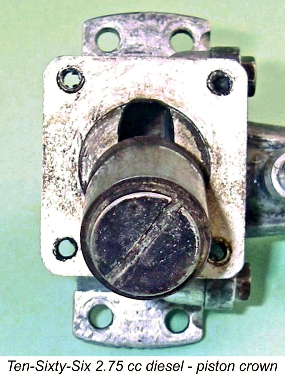
At the top, the A real quality touch is the use of 6 BA hexagonal-head machine screws to secure both the cylinder casting and the front cover to the crankcase. The four screws used to secure the cylinder have added slots to facilitate their removal and re-installation by allowing the use of a screwdriver once they have been slackened off with a wrench. While the use of a triple-webbed detachable front cover retained by three screws is yet another Ten-Sixty-Six characteristic, only the Arrow of 1949 also used a detachable cylinder casting. This may speak to a relatively late 1940's date for this engine. Primary induction is sideport by way of a conventional rectangular piston-controlled port at the rear. This opens at 45 degrees before top dead centre for a total period of 90 degrees. However, perhaps the engine’s most remarkable feature is that weird little vertical fitting on the top of the main bearing. This is clearly an original feature, since It might be supposed that this fitting is an oil reservoir, but in fact its open end is stopped by an alloy 4 BA machine screw. It is connected to the crankcase through a conventional small-diameter crankshaft front rotary valve (FRV) intake system. It thus appears that the fitting is an adjustable supplementary FRV air induction system to allow a degree of fine tuning. It is timed for the conventional running direction, opening at around 60 degrees after bottom dead centre and closing just before top dead centre. This makes the engine uni-directional, at least when the FRV system is open. It also confirms that the engine was intended to run in the conventional anti-clockwise direction viewed from the front. The effect of opening the FRV intake is of course to increase the engine's ability to draw air into the crankcase during the induction phase by lengthening the induction period. It might appear that the same result could be achieved simply by increasing the sideport induction venturi throat diameter, but then there's the timing issue. Increasing the venturi bore diameter would leave the induction timing unaffected, whereas the addition of the FRV system extends the induction period quite radically. The two systems actually combine to yield a total induction period of no less than 165 degrees! Of course, this will come at a price. Even though its diameter is very small, the fact that the FRV induction system opens 75 degrees in advance of the sideport induction aperture will significantly reduce the negative pressure in the crankcase when the sideport induction system opens. This is bound to have a very detrimental effect upon the available suction at the fuel jet. Apart from its potential to improve the engine's induction capacity somewhat, almost certainly at the expense of suction effectiveness at the sideport intake, one possibility that occurs to me is that this may have been seen as a device for assisting beginners in learning to start the engine by precluding any possibility of its starting backwards. As any user of classic sideport diesels knows, starting in reverse is by no means uncommon with such designs, often causing problems for beginners. Another possible motivation for this feature might be the protection of the screw-in crankpin (see below), which could easily become loose if the wrong running direction was initiated. Opening the FRV valve on this engine would make reverse running impossible, since it would destroy the crankcase compression on the power stroke when running in reverse. On the other hand, with the engine running in the normal direction, the FRV valve would improve the engine’s ability to fill the crankcase during the induction phase. Using the screw provided, the FRV intake can be set anywhere between fully closed and wide open. When closed, the engine functions as a normal sideport engine, with the FRV crankshaft porting being reduced to the still-useful role of supplying lubricant directly to the middle section of the main bearing. When open, Internally, the engine features a composite piston having an internal carrier for the gudgeon pin, which therefore doesn’t penetrate the piston wall. The carrier is retained by a very large slot-head screw, the head of which essentially forms the piston crown. This crown shows clear evidence of combustion residues, confirming that the engine has seen considerable use in the past. The 360 degree annular shoulder formed by the chamfered outer edge of the slot-head screw will serve as a piston baffle, at the expense of creating an extremely inefficient combustion chamber configuration at top dead centre. More of that in due course.
In terms of assembly, removal of the crankshaft and con-rod from the crankcase requires that the piston be disassembled so that the rod can be withdrawn downwards through its operating slot at the top of the crankcase while still attached to the crankpin. Since I have no idea how the assembly is configured, and since the whole thing appears to be nicely stabilized through considerable use, I have chosen not to disturb either the piston or the crankpin. I did however remove the front housing to expose the crankshaft. The crankshaft runs in a plain bearing which utilizes a two-piece thin-walled cast iron bushing pressed into the front housing in two sections from front and rear. The well-finished shaft is an outstanding fit in this bearing.
The unthreaded forward extension of the crankshaft is really unusual. This feature is more or less unambiguously indicative of a Ten-Sixty-Six product, since it appeared on a number of well-documented Ten-Sixty-Six models, including the successive 5 cc Falcon, Hawk and Arrow designs. This unique arrangement was intended to facilitate the fitting of a flywheel and clutch, since Ten-Sixty-Six were primarily involved with the model car market as opposed to aeromodelling. As far as I'm aware, no other British manufacturer ever employed this configuration. The long unthreaded forward extension is internally hollow for much of its length, but is unthreaded internally. Otherwise one might assume that it was for spinner attachment. As it is, you’d have to use an At the rear, induction is through a very nicely machined Mills-style intake venturi having provision both for the externally threaded needle and a screw-in fuel jet and pickup tube. The fuel jet projects into the middle of the intake venturi to promote improved suction. Needle tension is provided by a small coil spring. Although it has a somewhat unglamorous look externally, the quality of the engine’s construction where it counts is truly superb. Everything is first-class, right down to the hex head machine screws used to retain the cylinder casting and front cover. The state of the piston crown and contra-piston underside confirm that the engine has had a lot of use, but all fits remain absolutely beyond reproach. Compression seal is outstanding. In summary, this is a fascinating design which displays some unique features and has been extremely well executed by a maker (more likely than not someone associated with Ten-Sixty-Six Products) with first-class die-casting and machining capabilities. How well does it run?!? Let’s find out! The 2.75 cc Diesel on Test Having absolutely no operating data on this seemingly one-off engine, I had to operate on the educated guess principle when selecting an airscrew from my calibrated set to initiate testing of the unit. Taking my cue from earlier tests of the Allbon 2.8, I elected to make my initial attempts with an APC 101/2x6. To simplify operational issues, I began with the supplementary FRV intake fully closed, thus setting the engine up to operate in conventional sideport mode. With the chosen prop fitted, the engine felt really good on the bench - excellent compression with no trace of tightness at any point in the stroke apart from a slight (and desirable) "pinch" around top dead centre. Suction draw with finger-choking also seemed more than adequate - no evidence of any crankcase leaks. Given the fact that I wasn't expecting this to be a high-revving unit, I used a straight un-doped fuel with 30% castor oil, which engines of this type often prefer. All in all, I was confidently expecting to have little trouble with this test. Alas for rosy expectations!! I'm not exactly a rookie when it comes to diesel operation, having started my first diesel over 65 years ago, but this one gave me fits! It appeared that one had to get exactly the right amount of fuel into the cylinder for starting - no more and no less. Choking alone proved to be ineffective - all it did was flood the crankcase. A single choked flick was all that was advisable. I also found that I had to administer a prime of exactly a certain size to achieve a firing reaction to my efforts. I suspect that this extreme fuel sensitivity is related to the very inefficient combustion chamber configuration resulting from the shape of the large slot-head screw which forms the piston crown. Any liquid fuel in the combustion chamber at top dead centre will tend to pool in the annular channel surrounding the piston crown at its outer edge. This will tend to promote a locally-enriched mixture which may be reluctant to fire. Liquid fuel doesn't burn - it has to be in its vapour state within the fuel's explosive limits. In that regard, the annular pool of fuel will present a relatively small surface area for evaporation to occur. To make matters worse, it will be in close proximity to the cold cylinder wall, discouraging easy vaporization and ignition. Even when I eventually got it firing, the engine proved to be remarkably reluctant to start. It would fire easily enough but wouldn't keep running. It seemed to be having trouble carrying over from the initial firing stroke, in large part because try as I would, I couldn't seem to avoid getting excess fuel into the crankcase. I gained the impression that much of the prime was being channelled around the piston crown by way of the aforementioned annular channel and thence going straight down the transfer port. That excess fuel would "pool" in the lower crankcase and get thrown up into the upper cylinder by the first firing stroke, causing the engine to bog down and refuse to keep running. I tried "dry priming" with the exhaust port closed, but the engine was reluctant to even fire using this approach - it needs some fuel in the cylinder! In the end, the only remedy was to get the initial prime more or less right.
Once running, I found that response to the compression setting was very positive. The comp screw held its position dependably while remaining fully adjustable at all times. It was necessary to reduce compression somewhat as the engine warmed up, but once normal operating temperatures were approached things settled down nicely. The optimum compression setting was actually quite narrowly defined, due no doubt in part to the unusually coarse comp screw thread. At 18 threads per inch, it only takes a relatively small rotational movement of the comp screw to produce a substantial vertical shift of the contra piston. However, the feedback from the engine was very positive, making the optimum setting quite easy to find despite this characteristic. By contrast, the needle response seemed to be extremely ambiguous - the engine would keep running quite well with the setting all over the place! The very fine 6 BA needle thread (47.9 TPI) probably had something to do with this. Consequently, the "best" setting was rather poorly defined, but I eventually settled on around 1½ turns, give or take. At this setting, running was very smooth indeed. Having got the engine going on the 11x5 airscrew and established good running settings for that prop, I was subsequently able to get it started without too much trouble using the original APC 10½x6 and even smaller props. However, starting never became what I'd call easy - the starting mixture continued to prove critical. Things certainly improved as I became more familiar with the precise amount of prime required, but I'd still rate this as one of the more challenging diesels to start in my entire long experience of these little units. Definitely not a beginner's motor! It's probably one of those engines which would start far better in the inverted position, since this would both eliminate the pooling of fuel in the crankcase and spread the fuel in the combustion chamber over the entire contra piston surface. In performance terms, the engine proved to be rather a disappointment. Given what appeared to be a relatively free-breathing induction and transfer set-up by sideport standards, I had been expecting a performance comparable to, say, the Allbon 2.8 of similar vintage and displacement. What I actually got was something far more modest. The data set out below tells the story.
It turned out that the engine peaked in the region of 6,700 rpm, at which speed it developed around 0.097 BHP. It was pretty much done by 7,000 rpm, with a sharp drop-off thereafter. It has to be admitted that this is a pretty lacklustre performance even by late 1940’s standards. Based upon my own tests using the same calibrated airscrews, the contemporary original 1947 version of the similarly-sized Allbon 2.8 managed an output of 0.125 BHP @ 6,500 rpm. I suspect that the test engine's clearly inefficient combustion chamber shape may have a lot to do with this result. Coupled with the engine’s somewhat challenging starting characteristics, this test provided no indication whatsoever of any real merits which this unit may have possessed when running on sideport induction alone. It certainly impressed with the quality of its construction, showing absolutely no evidence of any mechanical distress during the test. Once going, it also proved to be a very smooth runner indeed. However, its challenging handling coupled with its low output made it a non-starter in contemporary marketplace terms. This is presumably why it evidently never progressed past the prototype stage. Which leaves one unanswered question – what about the role of that weird supplementary FRV induction system? Given the starting difficulties with this engine, I elected to save both time and effort by beginning my testing of this feature with the APC 10x6 prop, since that allowed the engine to operate at or near its peak with the FRV intake closed. I began by getting the engine going with the intake closed and then slowly and progressively opening it with the engine running. This was rendered rather difficult by the close proximity of the spinning prop disc, although it was possible with care. I ended up fitting a suitably-sized length of fuel tubing over the screw head to serve as a flexible extension for control purposes. Ugly, but effective ..........
This was undeniably accompanied by a noticeable improvement in performance. The engine ran just as smoothly as it had before, but the speed on the 10x6 prop had jumped from its former 6,300 rpm up to 6,800 rpm, implying an output of around 0.118 BHP at that speed. This was definitely a worthwhile improvement, bringing the engine more or less up to par with the Allbon 2.8. The impression gained is that this unit may have been constructed for the express purpose of testing the effectiveness of a combined FRV/sideport induction system. If so, it yielded a very positive result in terms of power output! Attempts to start the engine with the FRV system open proved if anything to be even more challenging than they had been during the initial sideport-only test. For obvious reasons, suction fuel draw at the sideport intake was way down – all that normal starting speeds accomplished was to draw air into the crankcase through the FRV system. The engine had to be spun up to a reasonable speed to generate any suction at all at the fuel jet. This pretty much dictated that the fuel level be matched to the fuel jet elevation. Finger-choking in the “normal” direction to fill the fuel line no longer worked at all since all that this accomplished was to cause air to be drawn in through the FRV intake instead of drawing fuel up to the sideport fuel jet. Fuel could be drawn to the carburettor by finger-choking in the “reverse” direction, and the engine could certainly be started in this mode. However, it continued to be far more difficult than one would normally expect – the amount of fuel in the cylinder remained critical and pick-up after starting was very uncertain. For this reason, I elected to conclude the test at this point – my flicking finger had had enough! In any case, I'd learned what I needed to know. If, as I now suspect, this was an experimental prototype built with the express purpose of trying the combination sideport/FRV induction system, it certainly showed that the system had merit in performance terms. Starting was another matter – the greatly reduced suction and the need to choke in reverse added to the prevailing difficulties, also making the engine uni-directional in operation. Given the fact that the FRV intake could be opened and closed at will, perhaps the intention all along was that the engine be started on sideport induction alone, with the FRV system being opened once the engine was running. An unnecessarily convoluted approach if so, and one which was only marginally justified by a somewhat enhanced performance. Moreover, my experience showed that it was rather hazardous to one's knuckles due to the proximity of the prop disc. In addition, the need to open the needle valve concurrently with the opening of the FRV intake added what I consider to be an unacceptable level of operational complexity. The experimental scenario seems to me to be far more probable. Overall, an interesting exercise on the part of whoever designed and built this engine! However, despite its technical interest it’s easy enough to see why this unit never resulted in any production version of which I’m aware. The undoubted performance merits of the combined sideport/FRV induction set-up scarcely justify its complexities. The same result could readily be achieved by using an FRV intake of larger size and dispending with the sideport induction arrangements altogether. Summary and Conclusion The basis for the tentative identification of this engine as having its genesis in the Ten-Sixty-Six workshops may be summarized in the following points:
Assuming that this engine is indeed a previously-unrecorded diesel prototype developed by Ten-Sixty-Six Products, as seems not unikely albeit not proven beyond doubt, it would most probably have been intended for sale as a kit of parts for home construction. In such a case, the final bore dimensions would have been left up to the constructor. Furthermore, its primary intended use would have been for model car applications, in which case it would have been fitted with a flywheel and clutch. This would explain the unique configuration of the front end of the crankshaft. Aero constructors would have been free to trim the shaft and extend the prop mounting thread rearwards as desired. As far as I can learn, Ten-Sixty Six never advertised a diesel model, making this a prototype as opposed to a production design if they were indeed involved. That said, whoever was resonsible for this engine must have entertained ideas about putting the engine into production in kit form at least, since they went to the trouble and expense of making a set of dies for it. Among British manufacturers, this was generally a sure sign that series production was envisioned.
Ten-Sixty-Six Products terminated their manufacturing program in 1950 after significantly over-producing most of their products in a declining market for model car accessories. If they were indeed involved in this engine's construction, it must date to the late 1940's. In design terms, it was well behind emerging trends as of that period. The inclusion of the supplementary FRV valve was most likely an experiment to see if such a feature would keep the sideport layout competitive against the rotary valve designs which were then coming to the fore. If so, it didn't convince the designer, any more than it convinced me. That fact alone would explain why the engine evidently never reached the commercial market. Still, a fascinating venture outside the box, perhaps by Geoffrey Hastings and his associates, with some quite original thinking on display! Unless someone out there can authoritatively prove the suggested provisional identification wrong, we can add another diesel to the long list of British designs of the early post-war era! ______________________________ Article © Adrian C. Duncan, Coquitlam, British Columbia, Canada First published December 2018
|
||
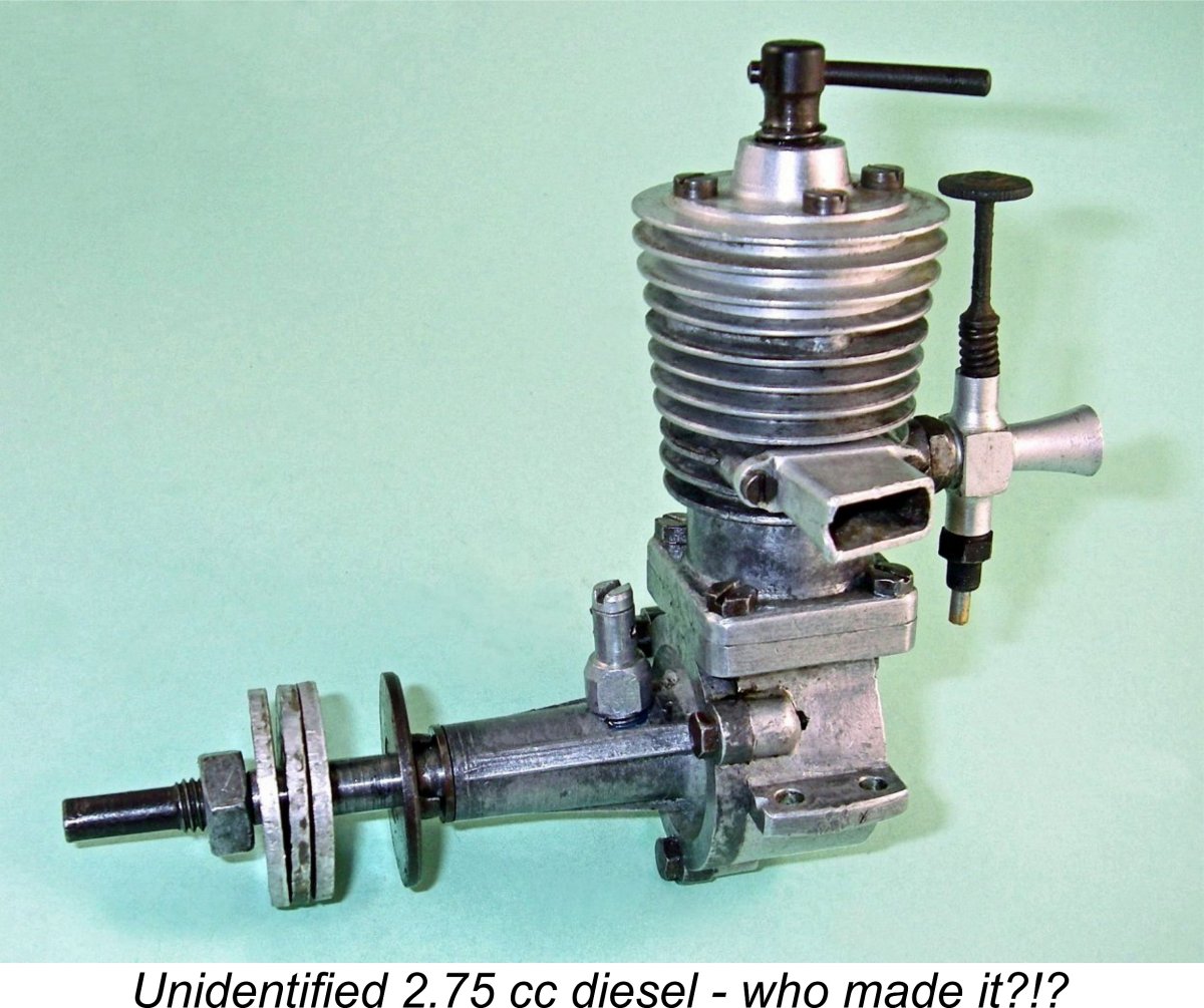 Once in a while something falls into one's lap that seems to have the potential to shed light upon a previously unrecorded piece of model engine history. A case in point is the 2.75 cc diesel which forms the central subject of this article. Although definite proof is lacking, the present general consensus is that this is more likely than not to be a previously-unattested prototype having its origins in the workshops of the
 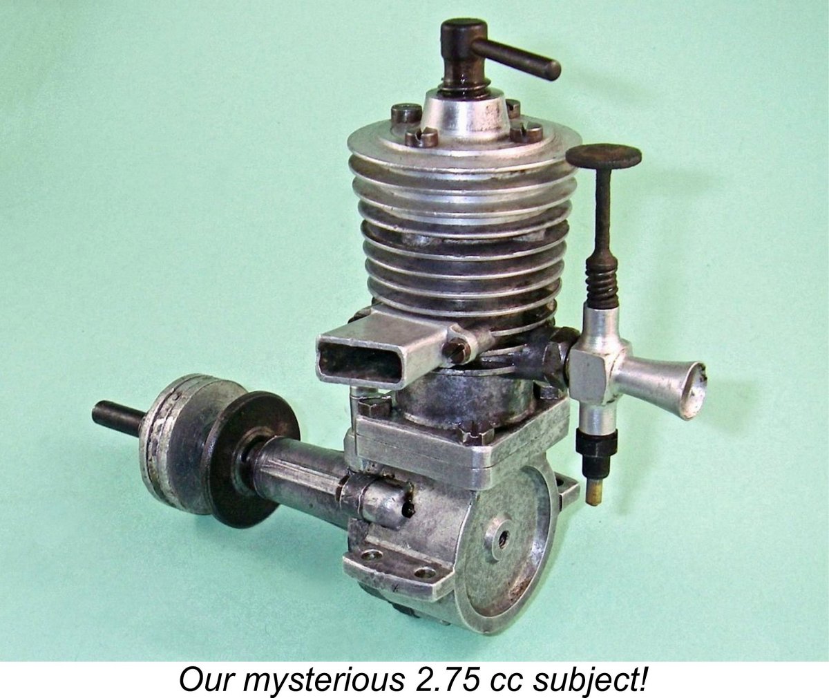 A few bidders pushed me hard, certainly suggesting that more than one interested party knew exactly what they were going after – undocumented home-builds from unknown makers don’t usually generate that much interest. And there was more - apparently after the auction closed, one of the unsuccessful bidders went so far as to offer the seller quite a bit more money than my winning bid to try to persuade him to renege on my eBay win! That guy at least must have recognized the engine and seen it as having a high value. Since the seller was a person of integrity who values his eBay standing, he naturally didn’t go along.
 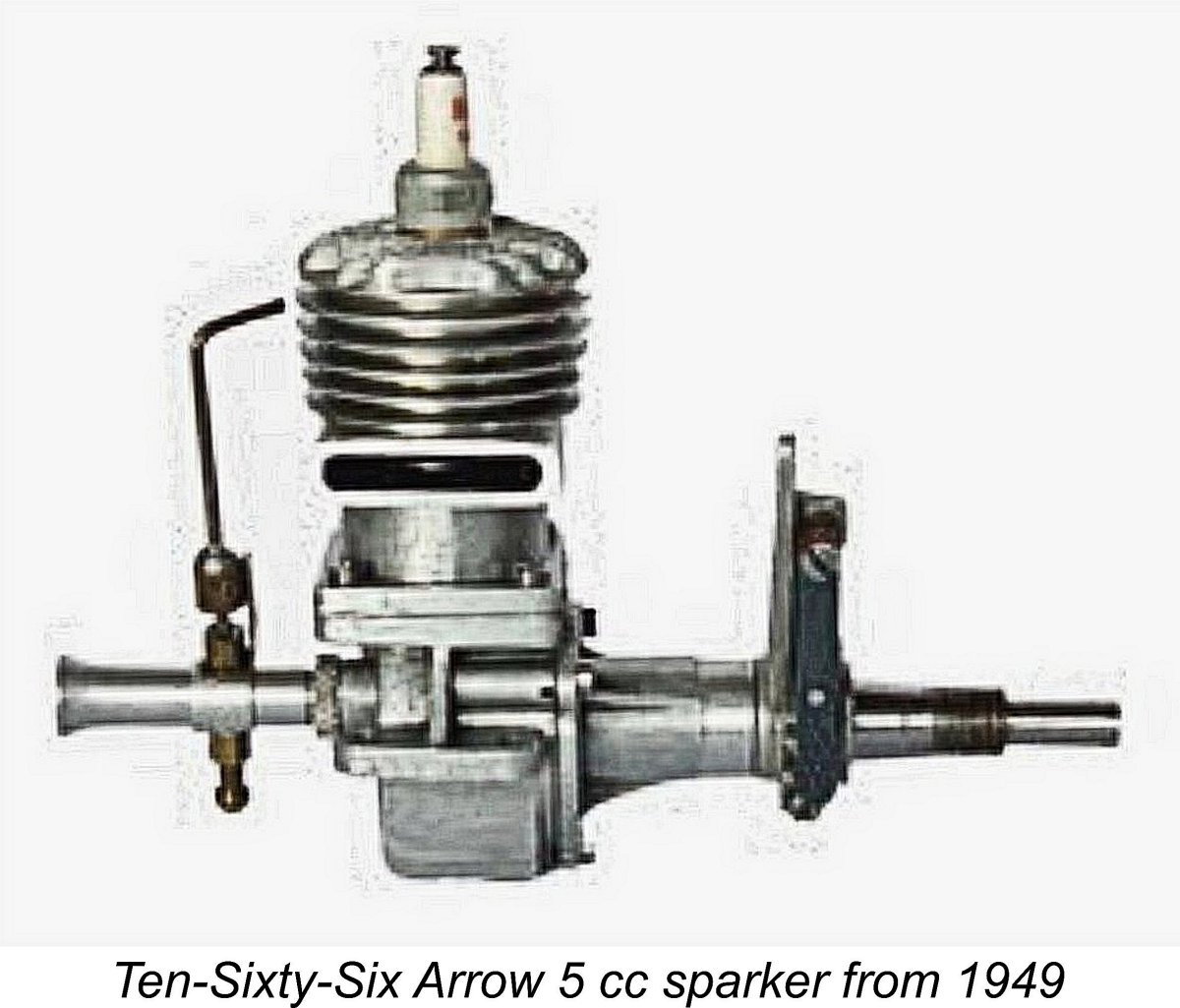 However, the most persuasive suggestion of all came from my valued English friend Miles Patience. He and his very knowledgeable father, the late Mike Patience, both reckoned on architectural grounds that this was a previously-unattested diesel prototype originating from the workshops of
 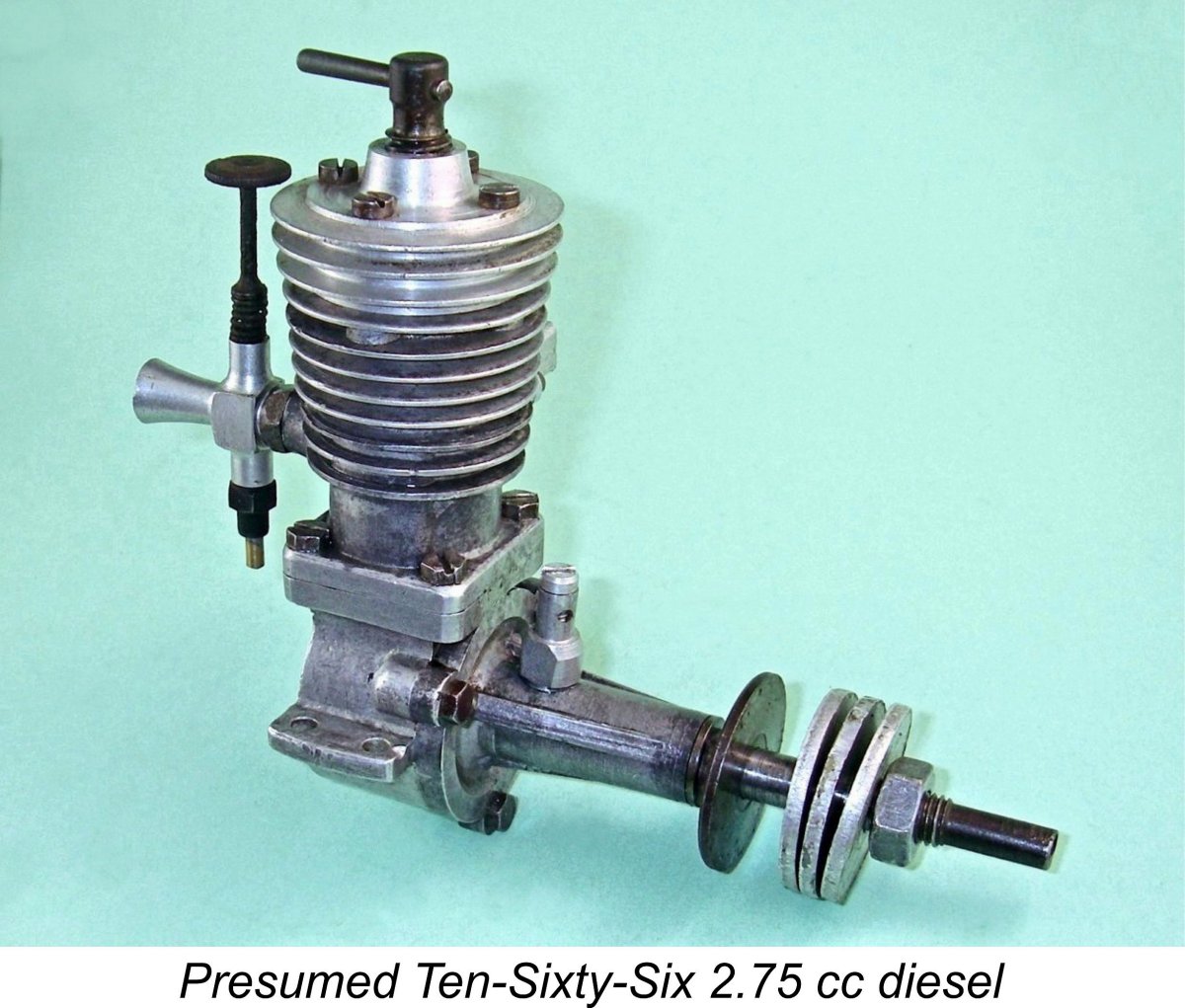 Whoever produced this engine, it was immediately clear from the outset that it was of British origin. The assembly screws are all BA items, the prop nut thread is ¼-26 BSF, the needle valve is threaded 6 BA and the comp screw thread is
 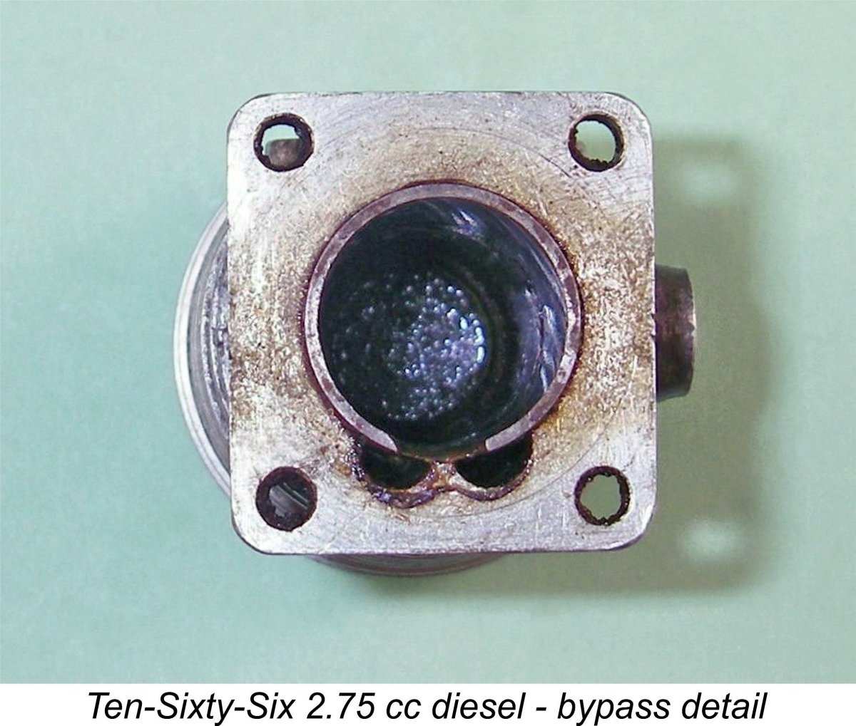 The single rectangular transfer port is fed through two generously-proportioned vertical channels in the inner wall of the cylinder jacket which communicate with the lower crankcase. The transfer overlaps the exhaust to a significant extent. The die-cast exhaust stack is secured to the cylinder casting by two 10 BA machine screws. It must be admitted that no other Ten-Sixty-Six product exhibited this feature.
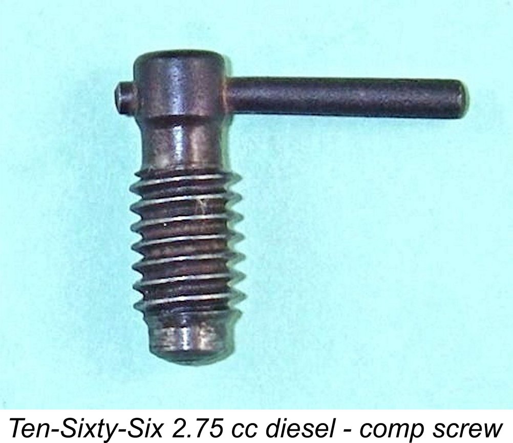
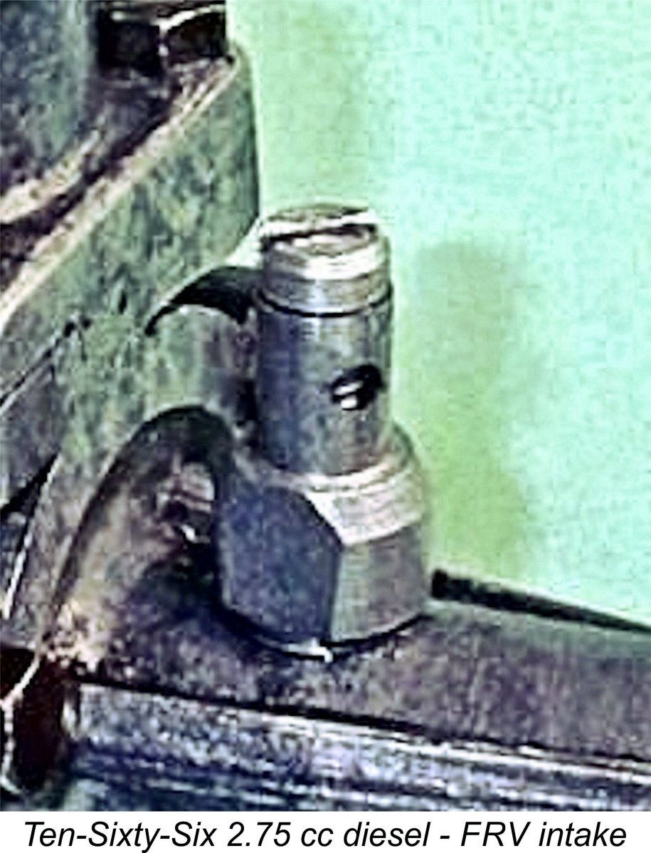
 the screw remains in place and air is admitted to the FRV system through two opposing holes on the sides which are progressively opened by the withdrawal of the set screw. You can see one of them in the above close-up view of the fitting. Very much like an air bleed on an R/C throttle. I strongly suspect that the screw originally had a small coil spring for setting retention.
 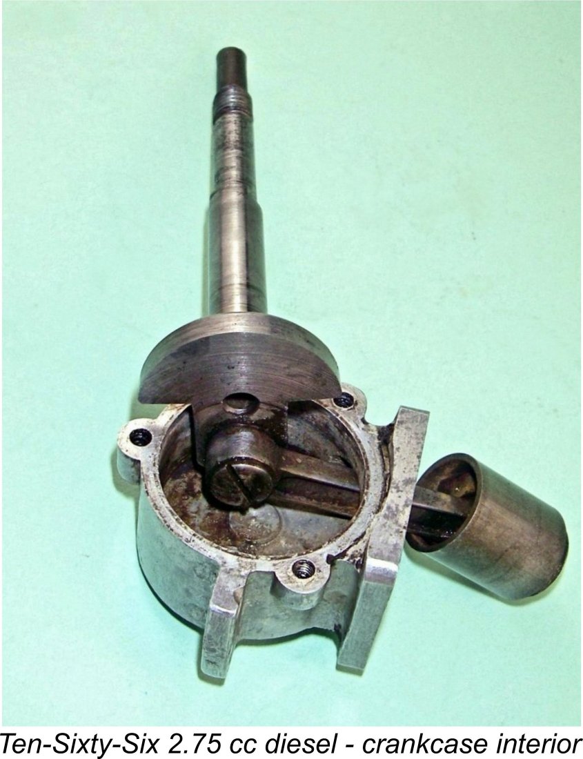 The con-rod is a work of art – fully machined from steel to a very sturdy I-beam section with generous bearings. This is very much a characteristic of Edgar Westbury's work. The crankpin is apparently a screw-in item, which should have a left-hand thread if the maker knew what he was doing. I didn’t try removing it to find out.
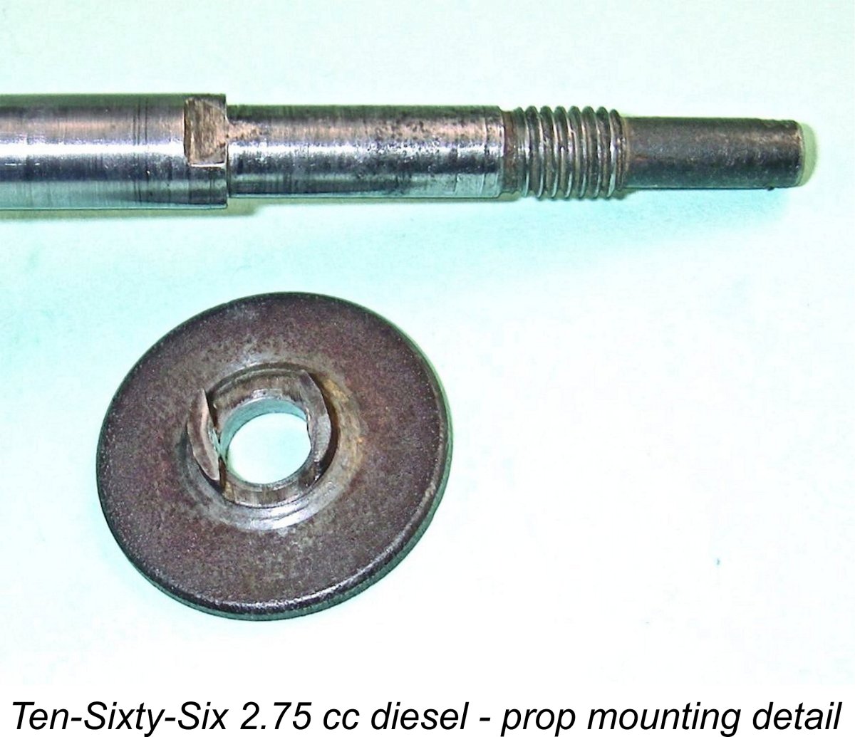
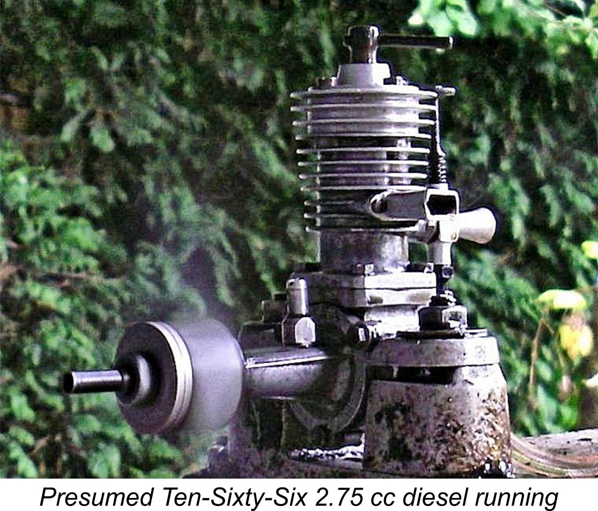 To help with the carry-over issue, I switched to a Taipan 11x5 prop for increased flywheel effect. This turned out to be a very positive move, to the point that I was eventually rewarded with a start. Even with minmal preliminary choking, the engine started up really rich and smoky as the excess fuel in the crankcase burned off, thus confirming my impressions regarding the disposition of much of the cylinder prime. However, the engine quickly cleared its throat and settled down to some very smooth running. The exhaust note was strong and steady, while the exhaust residues remained clean, with minimal smoke.
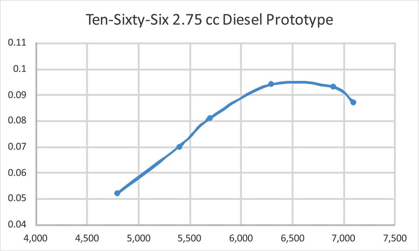
 The initial result of this was a clear indication of fuel starvation - the effect was more or less the same as leaning out the needle beyond the optimum setting. As the FRV intake was opened, I had to open the needle setting at the same time to restore smooth running. I ended up at almost a full 2 turns of the needle richer with the FRV intake fully opened. The implication of a significant reduction in suction is obvious.
  Taking the above points together, it becomes really hard to see this engine as anything other than a development prototype having its origins in the Ten-Sixty-Six workshops. Some may object that the engine's displacement is inconsistent with Ten-Sixty-Six's usual intention of using it for car applications, since it did not correspond to any then-current British car class. However, if the primary objective was to test the effectiveness of the combined sideport/FRV induction systems, the displacement of the test prototype would be irrelevant. The same would apply if aircraft applications were envisioned, as witness the
| |