
|
|
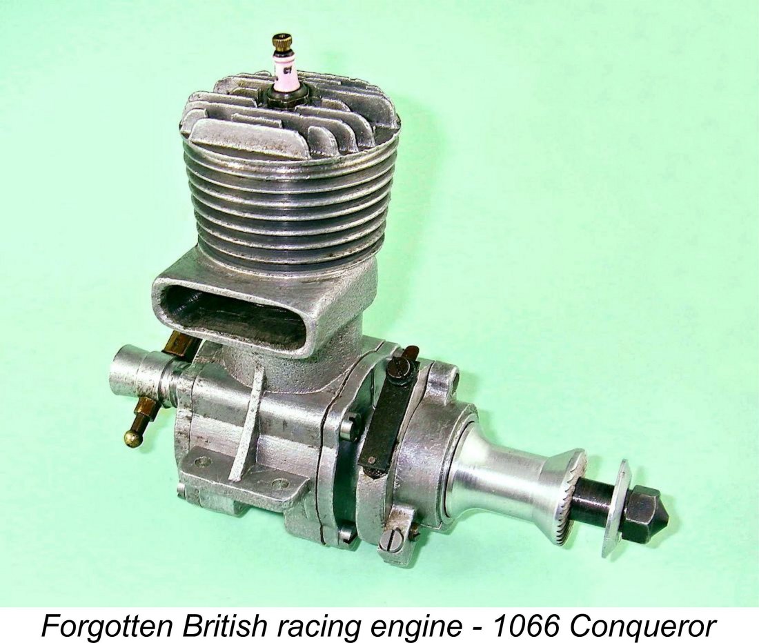
1066 and All That - the Forgotten Conqueror
In a previous article published in October 2004 on the late Ron Chernich’s now-frozen “Model Engine News” (MEN) website, a limited amount of information was provided regarding the rather obscure British Ten-Sixty-Six range, including some discussion of a number of the 5 cc models offered by that manufacturer. The firm's 10 cc racing engine known as the Ten-Sixty-Six Conqueror was mentioned but not discussed in depth. Readers wishing to learn more about the Ten-Sixty-Six 5 cc models are referred to the earlier article. The present text will focus on the 10 cc Conqueror. I plan to cover the 5 cc Ten-Sixty-Six Hawk in a future article. In stating that this classic British racing engine has tended to be overlooked, I have to admit that I was originally guilty as charged myself - despite its earlier mention in the 2004 article on MEN, I forgot to include it as part of the domestic competition in my subsequent June 2008 MEN write-up on the Nordec 10 cc motors! The revised version of the Nordec article which now appears here on my own site remedies that deficiency as well as a few others. That said, I wasn’t alone here - even the usually comprehensive Peter Chinn overlooked the Conqueror in his retrospective on classic racing engines entitled “Exit the Racing Engine?” which appeared in the March 1956 issue of “Model Aircraft” magazine - the only British-made racing units mentioned in that article were those from Nordec, Rowell and ETA. So I was in very good company!
This wonderful site is still very much alive today (2026), constituting an absolute gold-mine of information on tethered car and hydroplane racing past and present. Some of the engineering that goes into these models and the engines that power them is quite remarkable, and any of my readers will find something of interest there. Highly recommended! I‘m deeply grateful to On The Wire's Hugh Blowers, who is almost certainly the world's leading authority on Ten-Sixty-Six. As always, my mate Hugh was most generous in providing information and images as well as reading my original draft text to keep me on the right track. In addition, Hugh was kind enough to provide me with my own copy of his very detailed write-up on the life and times of Ten-Sixty-Six founder G. I. Hastings and the products of the company. The pooling of information in this manner between two groups of researchers who are approaching the same subject from different angles can only be beneficial both to the researchers involved and to their readers. I'm proud to include Hugh among my valued friends and colleagues.
Quite apart from the availability of a huge amount of information from the above sources, the arrival of a more or less unused Conqueror Mk. I built from a kit to a very good standard allowed me to delve into the engine and describe it more fully for the record. For these reasons, it appeared to me that a further article on the Ten-Sixty-Six range in general and the Conqueror in particular was well justified.
As its title suggests, the present article will focus primarily on the Ten-Sixty-Six Conqueror engine itself. However, the Conqueror was just one of an amazing range of products offered by the company. Readers wishing to know more about the full scope of the Ten-Sixty-Six venture are strongly urged to consult the highly informative On The Wire web site mentioned earlier. There's far more in the Ten-Sixty-Six article on that site than I intend to present here! Having acknowledged the very considerable assistance provided to me by the above friends and colleagues, I must emphasize that the responsibility for any errors or omissions in the following text rests with me and me alone. For convenience, I’ll begin by summarizing the history of the Ten-Sixty-Six company before discussing the Conqueror in detail. Background The main reason why the Conqueror and its manufacturer appear to have been largely overlooked by today's predominantly aero-minded model engine aficionados is the fact that the company concerned was very much focused on the production of engines and accessories for tethered model car racing, with a subsidiary interest in tethered hydroplane racing. Their involvement with model aircraft appears to have been very much peripheral to their other interests. It's often forgotten by today's aeronautically-inclined enthusiasts that between them model car racing and tethered hydroplane racing rivalled aeromodelling in popularity among early post WW2 British power modellers, paralleling the similar situation in the USA, at least with respect to cars. At that time, I/C powered car racing in particular enjoyed a level of support which was only to be regained many years later with the refinement of radio-controlled I/C powered car racing during the past 30 years or so.
Regardless, the effect of this ban was to ground a sizeable number of perfectly serviceable model aero engines, leaving a group of frustrated power modellers very much open to alternative suggestions for interim use of these engines. For reasons which remain obscure, the operation of model I/C engines for purposes other than flying was not prohibited - rather strange in view of the understandably severe rationing of petrol (gasoline) which prevailed at the time. “Aeromodeller” publisher D. A. Russell was not slow to recognize the pent-up frustration which existed among power modelling enthusiasts. In September 1942 the magazine featured the first of a series of articles promoting the use of the grounded model aero engines to power model racing cars. A set of rules was quickly established for the During the WW2 period, British enthusiasts necessarily had to work with chassis, accessories and in some cases engines of their own making, since no such items were commercially available during the war years or for some time thereafter. Some of the resulting engines were extremely competitive - Hugh Blowers tells us that Gerry Buck's rather crudely-constructed but clearly powerful Following the conclusion of hostilities, model car racing experienced a huge upsurge of interest in Britain, with new clubs and tracks appearing almost on a weekly basis. This activity in turn drew the attention of commercial interests to the hobby, and firms supplying goods related to model car racing quickly began to appear. At the peak of the model car boom in the late 1940’s, it's estimated that there were over 50 such firms in existence in Britain! The growth of the hobby was sufficiently rapid to promote the establishment of “Model Cars” magazine, which published its first issue in September 1946. A second publication, “Model Car News”, soon followed - like aeromodelling from 1949 onwards, the model car movement was sufficiently strong at the time to support two competing magazines. It was in response to this very dynamic trend that our subject manufacturer, Ten-Sixty-Six Products, was established. Let’s take a closer look at this company. The Manufacturer
Hugh Blowers' painstaking research has revealed that Hastings was a highly enigmatic figure who appears to have led something of a double life while at the same time avoiding having his photo taken whenever possible! For reasons which remain obscure, he generally conducted his private affairs under the name of Geoffrey Prescott, using his legal name of Hastings only when required to do so in connection with his business or legal interests. The Worcester electoral roll confirms that he had unquestionably established the Prescott persona by 1939 at the age of 32. Hugh's investigations leave no room for doubt that Geoffrey Prescott and Geoffrey Hastings were one and the same person. Some measure of skullduggery or devious practise seem to be implied here ........for most of us, one name suffices (although more colourful names may be unofficially “assigned” by others!!). Right up to 1951, Hastings went so far as to maintain an address under the name Prescott at 80 St. Dunstan’s Crescent in Worcester, which he used as his home address in that persona.
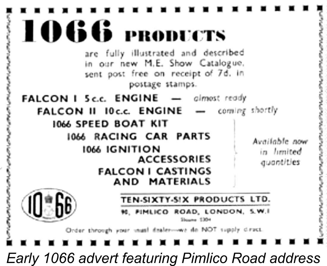
The company's head office was located at 26 Battenhall Road in Worcester, although a few early advertisements gave the address as 90 Pimlico Road, Pimlico, London. It seems likely that this was an address of convenience, as was a short-lived registered office location at Selly Oak, Birmingham. The And therein lies a tale! 26 Battenhall Road had formerly been the residence of builder and property speculator William Bennett, his wife Clara and daughter Gertrude (1897-1986), who preferred to be known by her second name of Millicent. William had been very successful in business, and when he and his wife both died in 1941 the 44 year old Millicent became the owner of the property (and many others besides) along with a significant portfolio of lucrative business interests, some of which she had previously developed independently herself in her own interest. Now extremely wealthy but still single, she continued to reside at 26 Battenhall Road. The nearby property at 80 St. Dunstan’s Crescent had been rented by “Geoffrey Prescott” from the aforementioned William Bennett. It shared a common boundary with the Battenhall Road property where Millicent Bennett continued to reside. Upon her father's death in 1941, Millicent had naturally become “Prescott’s” landlady. She evidently became personally acquainted with The large area at the rear of the Battenhall Road property accommodated a number of outbuildings which had been used formerly by the now-deceased William Bennett in support of his building company. These buildings were of course now owned by Millicent Bennett. In 1945 one of them became the Ten-Sixty-Six workshop. A certain amount of light work such as fettling of the castings, assembly and packing was evidently carried out at this location. However, the actual components were produced elsewhere. The castings originated from a company called W. E. Salter Die Casting Ltd. which was operated by a toolmaker named Bill Salter. This company occupied premises in somewhat distant Cinderford, Gloucestershire. Conveniently enough, an involvement with this company was one of Millicent Bennett’s many ongoing business interests. The piston rings and liner blanks were supplied by the well-established firm of Wellworthy, who were located in Lymington, Hampshire. Hugh Blowers suspects that other precision components may have been produced by Craftsmanship Models in Ipswich, Suffolk although there is presently no hard confirmatory evidence for this. They were certainly not produced at Battenhall Road. Hastings seems to have pursued a rather lavish lifestyle, which is somewhat at odds with the fact that for much of his life he appears to have had no visible sources of income - handy when the tax man came to call! Of course, this was possible only because that lifestyle was heavily subsidized financially by Millicent Bennett, along with the operations of both the Ten-Sixty-Six and Salter companies. Indeed, Hastings became in effect a "kept man" - Millicent was to finance his various activities throughout the remainder of his life, even going so far as to buy him a full-sized "company aircraft" (an Auster J/1 Autocrat) in 1947. One can only hope that Millicent received good value for her money …….!! The two lived together as husband and wife, although they appear never to have married.
The design of the Ten-Sixty-Six engines was strongly influenced by the fact that Hastings was a close friend of the legendary Edgar T. Westbury, a staunch advocate of home construction of model engines. In fact, it appears that a primary motivation for the establishment of Ten-Sixty-Six Products was Hastings' wish to capitalize on Westbury's design concepts. There's no mistaking the Westbury influence upon most of the engine designs offered by the company.
Although not particularly competitive either, the company’s 10 cc Conquest car was a really nice-looking model. My English friend David Giles still runs a car based upon this design, although The model engines offered by the company included the Falcon 5 cc side-port model (their initial design, showing strong Westbury influence); the Hawk 5 cc disc rear rotary valve (RRV) model featuring a screw-in cast-iron cylinder; the Arrow 5 cc RRV model, which was a development of the Hawk featuring a separate aluminium cylinder attached by 4 screws; and our main The company took its development work very seriously, to the extent of establishing and maintaining its own private 70 foot track at Ambrose Farm adjacent to the Laughern Brook in the St. John’s suburb of Worcester for testing and
The kits were generally fairly basic, consisting of plans, rough castings, materials and fastenings. The accompanying illustration of a surviving Conqueror kit which turned up in 2004 is representative of the company's products. It took a fair amount of skilled model engineering work to complete an engine from these kits. One of the most challenging components was obviously the crankshaft. Finished crankshafts were sold separately for those who preferred to side-step this particular challenge.
The Ten-Sixty-Six venture was clearly a labor of love for Hastings - whatever his other failings, he appears to have been a genuine enthusiast. He was quite energetic in promoting the company, placing regular advertisements in specialist publications (notably “Model Engineer”, “Model Cars” and “Model Car News”) from early 1946 to mid 1950 extolling the virtues of the company's various products in fulsome terms. Interestingly enough, the first few advertisements, in which the introduction of the Falcon series in 5 cc, 10 cc and 15 cc models was highlighted, were taken out under the name of G. I. Hastings of 26 Battenhall Road, Worcester, with no mention of Ten-Sixty-Six Products. Subsequent advertisements all used the Ten-Sixty-Six name.
In addition to his ongoing support for tethered car racing, Hastings also regularly donated kits, parts and motors as prizes for aeromodelling and hydroplane events. However, winning did not always garner the proffered rewards! The late Ray Monks (1928-2018), winner of the Hamley Trophy in 1945 and later a member of the British national free flight team, experienced this at first However, this turned out to be a merely symbolic presentation, since Hastings immediately took the engine back from Ray, proclaiming that it was “faulty” and that he needed to rectify the problem before returning it to Ray. As matters transpired, that was the last that Ray ever saw of “his” Falcon! The reasons why the Conqueror and its smaller relatives never achieved the profile of some of their competitors in aeromodelling circles should now be readily apparent. The company maintained an unswerving focus upon model car racing along with a Hastings' promotional activities in the aeromodelling field appear to have been essentially confined to the sponsorship of a few aeromodelling events along with the sporadic placement of one or two advertisements in the aeromodelling media. Note that the advertisement reproduced here from the July 1946 issue of "Model Aircraft" cites yet another address, this time in Beckenham, Kent! Hastings appears to have gone out of his way to create uncertainty regarding his actual location! Consequently, most of the aeromodelling fraternity remained in ignorance of the very existence of the Ten-Sixty-Six engines. It's a little hard to understand the company's deliberate restriction of their potential customer base in this way, since their engines were perfectly suitable for model aircraft use and might well have achieved some level of consumer acceptance in that field. Another issue that almost certainly had an adverse effect upon the company's fortunes was the fact that the very ambitious production program implied by the wide range of products on offer proved in the event to be impossible to maintain, at least initially. As a result, shipments to dealers were greatly compromised and the company frequently failed to meet delivery expectations. This situation seems to have reached a head in late 1947, when available inventory had become essentially non-existent and there was nothing to send out to the dealers. It was clearly only the ongoing financial support of Millicent Bennett that kept the company afloat during this period.
An additional impediment to the achievement of wider success was the previously-noted fact that for the most part the engines were offered as kits for home construction rather than as complete factory-built units. This meant that a significant level of mechanical capability was required to complete them, in terms of both skill and equipment. Accordingly, they appealed primarily to the Motor Boys of the 1940's rather than the mainstream aeromodellers who mostly lacked the facilities to construct engines from plans, castings and basic materials. Given the choice, most aeromodellers would understandably opt for one of the factory-made units from other companies which were becoming increasingly available and affordable at the time.
At a time in Britain when a man grossing £8 a week was considered well-off, this represented a major impediment to widespread participation in the sport. In effect, the pursuit of model car racing at a competitive level had become an elite activity open only to those having the right combination of money and technical ability. Naturally, such individuals were very much in a minority - Rowell 60 designer Wilf Rowell estimated in 1950 that there were only a "few hundred" serious British participants in model car racing at that time. He was probably not far wrong. By contrast, the additional financial outlay and technical expertise required to create a suitable model aircraft once one owned an engine were relatively minimal. The same engine could easily be used in a number of models, even on the same day. Moreover, venues for the operation of model aircraft were far more numerous around the country than those for model car and hydroplane racing. Aeromodelling thus remained a far more accessible branch of the power modelling hobby, and the relative numbers of participants increasingly reflected this. Ten-Sixty-Six might have achieved considerably greater and more long-lasting commercial success if they had catered to this market also, rather than focusing upon cars. In particular, the development of a diesel unit for model aircraft There is some evidence to suggest that they may well have contemplated taking just such a step. During the run-up to the 1947 “Model Engineering Exhibition”, rumours circulated that a diesel model would be among the products to appear on the Ten-Sixty-Six stand. However, such an engine failed to materialize at the Exhibition. There the matter rested until a few years ago, when a well-made 2.75 cc sideport diesel showing unmistakable signs of Ten-Sixty-Six involvement fell into my hands. Although I can’t prove it, there’s considerable circumstantial, architectural and technical evidence to suggest that this engine was a prototype of a potential Ten-Sixty-Six diesel model. This seemingly unique powerplant displayed a number of unusual features, not the least intriguing of which was an adjustable supplementary crankshaft front rotary valve (FRV) induction system to go along with its basic sideport arrangement. It performed well on test, as recorded in my separate article on this very interesting design. However, if it was a Ten-Sixty-Six test piece, the project came to nothing in the end - Ten-Sixty-Six Products never released a diesel in any configuration. A further challenge was the increased competition faced by Ten-Sixty-Six as time went by. As of late 1945 when the company was founded, there was little competition since the post-war model car racing boom was only just getting started in Britain. Indeed, Ten-Sixty-Six Products were among the pioneers in the field. However, by the late 1940’s there were around 50 firms supplying the needs of British model car racing enthusiasts, some of them competing for the very same turf occupied by Ten-Sixty-Six Products. Rowell Motors of Dundee, North Downs Engineering (Nordec) of Whyteleafe in Surrey and Z.N. Motors of Willesden in London come immediately to mind, and there were others.
The same was true of Ten-Sixty-Six's approach to the design of their model cars and accessories. Their competitors Rowell and Z.N. both pursued the development of their car designs through hands-on competition experience at the highest levels, manufacturing cars and components that reflected current American trends. By contrast, Ten-Sixty-Six never embraced the out-and-out racing market, consequently failing to develop competitive designs. To make matters even worse, by 1950 the tethered model car racing boom had peaked and was already beginning the fairly rapid slide from prominence which would see it virtually disappear in Britain by 1955, not to begin a recovery until a further half-century had passed. So the various firms were competing for their share of a steadily-decreasing market that was never all that large in the first place. As a result of all the above factors, the Ten-Sixty-Six venture failed to sustain the level of commercial success required to justify its continuation. Indeed, it's pretty clear in hindsight that the company had never at any time come close to being financially sustainable, having been kept afloat as long as it was purely through the ongoing injection of capital by Millicent Bennett. It might be more accurate to see the activities of the company as Geoffrey Hastings' subsidised hobby rather than as a legitimate business venture! Obviously this could not continue indefinitely, the inevitable result being that the company was wound up in the first half of 1950. Hugh Blowers reports that the final advertisement in “Model Car News” appeared in January 1950, while the last-ever “Model Engineer” placement was published in the July 1950 issue. Production had greatly outstripped sales over the later life of the company. Consequently, a great deal of inventory remained unsold when it ceased trading. Some retailers were still advertising a range of Ten-Sixty-Six items a decade later and new kits and parts still show up periodically today. The operations of W. E. Salter Die Casting Ltd. at Cinderford were continued until late 1953, when that company too went into voluntary liquidation. The circumstances surrounding the winding-up of the Salter company reflected little credit upon Hastings' business ethics, since it transpired that he had made highly questionable use of his position as a Director and was pursued for the return of a substantial sum of improperly allocated funds. One of the suppliers who was caught up in the fall-out from this venture commented for the record that he had "... a very poor opinion of Mr. Hastings' business methods". Indeed, all who actually knew him personally tended to describe the moral and ethical aspects of his character in less than favourable terms. Enough said, methinks. Hastings seems to have survived this episode somehow, continuing to live in easy circumstances with Millicent Bennett at a new address in Falmouth, Cornwall. Interestingly enough, they resided in Falmouth under the name Prescott! Although Millicent must have lost many thousands of pounds on the Ten-Sixty-Six venture, at least she had the money to lose! She stuck loyally with Hastings regardless, going on to support him in a sport-fishing charter venture based on Looe in Cornwall. However, Hastings did not live long to enjoy Millicent's continuing favors, being killed in a motor vehicle accident in 1957 at the age of fifty. The sixty-year old Millicent was with him at the time. Although seriously injured, she survived the accident, living on to the grand old age of 89. The 10 cc Conqueror - Background and Development
It's interesting to observe that all three of the above-mentioned designs appear to have been inspired by a genuine passion for the modelling hobby on the part of their It's a little-known fact that there were very nearly two more commercial British 10 cc racing engine contenders at this time! The first of these stillborn efforts came from AMCO designer Ted Martin. Speaking to Jim Woodside many years later, Ted recalled looking over the emerging British opposition in late 1948 and making a strong pitch to the Directors of the Anchor Motor Co. for the development of a 10 cc AMCO racing engine with which to take them on. Perhaps wisely in view of the limited market together with the emerging competition, the Directors vetoed the idea, leaving Ted to focus attention upon the development of the very successful AMCO 3.5 series. There's little doubt that in commercial terms this was a far more productive use of Ted's time, but it's intriguing to contemplate the level of competition which a Martin-designed 10 cc racing engine might have offered to the other three competing models.
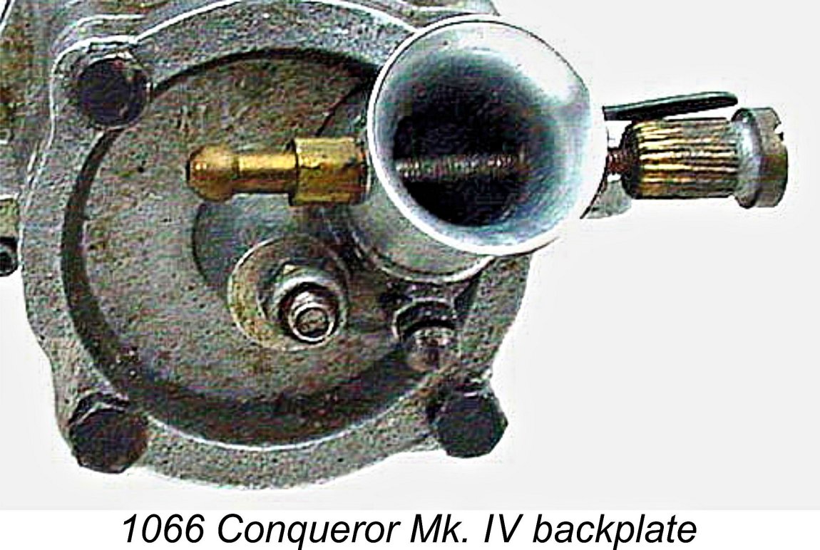
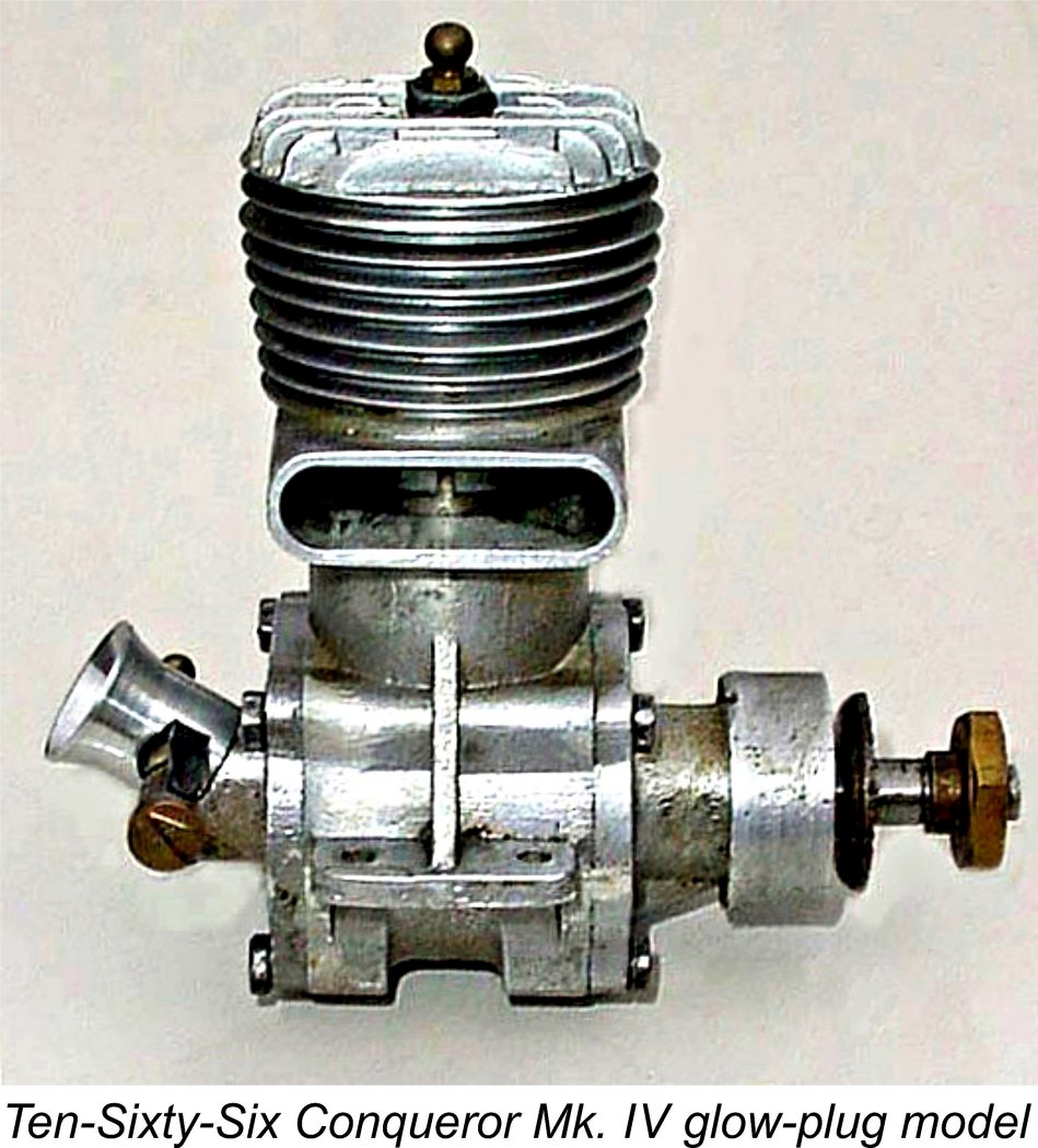
This engine was installed in George Stone's record-holding Lady Babs II (all three individuals were members of the Malden tethered hydroplane racing club). Some test runs on New Year's Day 1949 under less than ideal conditions confirmed that this engine had the potential to be a front-runner even against the American opposition. However, E.D. management were not receptive to the idea of producing this design in series, doubtless for similar reasons to those of AMCO management. Consquently, the Fireball proposal went nowhere, although Basil Miles' own subsequent 30 cc hydroplane motor was based directly upon the Fireball design. The 10 cc Conqueror which is our main subject was developed initially in its Mk. I form during 1948, with both spark ignition and glow-plug ignition models being offered. The illustrated example is a Mk. I spark ignition unit. This model was very much McCoy-influenced, although it retained some Westbury characteristics along with a measure of highly original thinking, as we shall see. The name of the actual designer is obscure - I very much doubt that it was Geoffrey Hastings! The price of the basic kit for the Mk. I Conqueror was a very reasonable £2 17s 6d (£2.88), but the purchaser then had a lot of skilled work to do! The Conqueror was also made available as a factory-produced ready-to-run unit at a cost of £8 5s 0d (£8.25) for the spark ignition version and £8 2s 6d (£8.13) for the glow-plug This led to the Conqueror being fairly widely adopted by clubman car racers, also seeing some service in tethered hydroplanes. However, the engine was not competitive in either application. Moreover, it seems never to have become anywhere near as popular in aeromodelling circles as its Nordec rival - in fact, I can find no record of the Conqueror having appeared in model aircraft competition. It appears that most of the Conquerors were sold in kit form to model engineering types with a primary interest outside of aeromodelling. The performance shortcomings of the Mk. I Conqueror soon became sufficiently obvious that at some point during 1949 a revised Mk. II version was developed. This featured an enlarged bypass passage, doubtless influenced by the then recently-introduced and far more powerful McCoy 60 Series 20. It was otherwise more or less identical to its Mk I predecessor. I have no information It appears that later in 1949 the development of a Mk. IV version was contemplated. A number of glow-plug examples of the engine appeared at that time with downdraft carburettors a la Dooling, albeit allied to Mk. II crankcases. The backplates in question were stamped "MK IV" - one wonders what became of the implied Mk. III model! In the accompanying image of the backplate, the "MK" portion of this marking is visible above the fuel nipple - the "IV" is evidently obscured by the nipple. The venturi used with this backplate had a significantly larger throat diameter than that used on the Mk. I and Mk. II models.
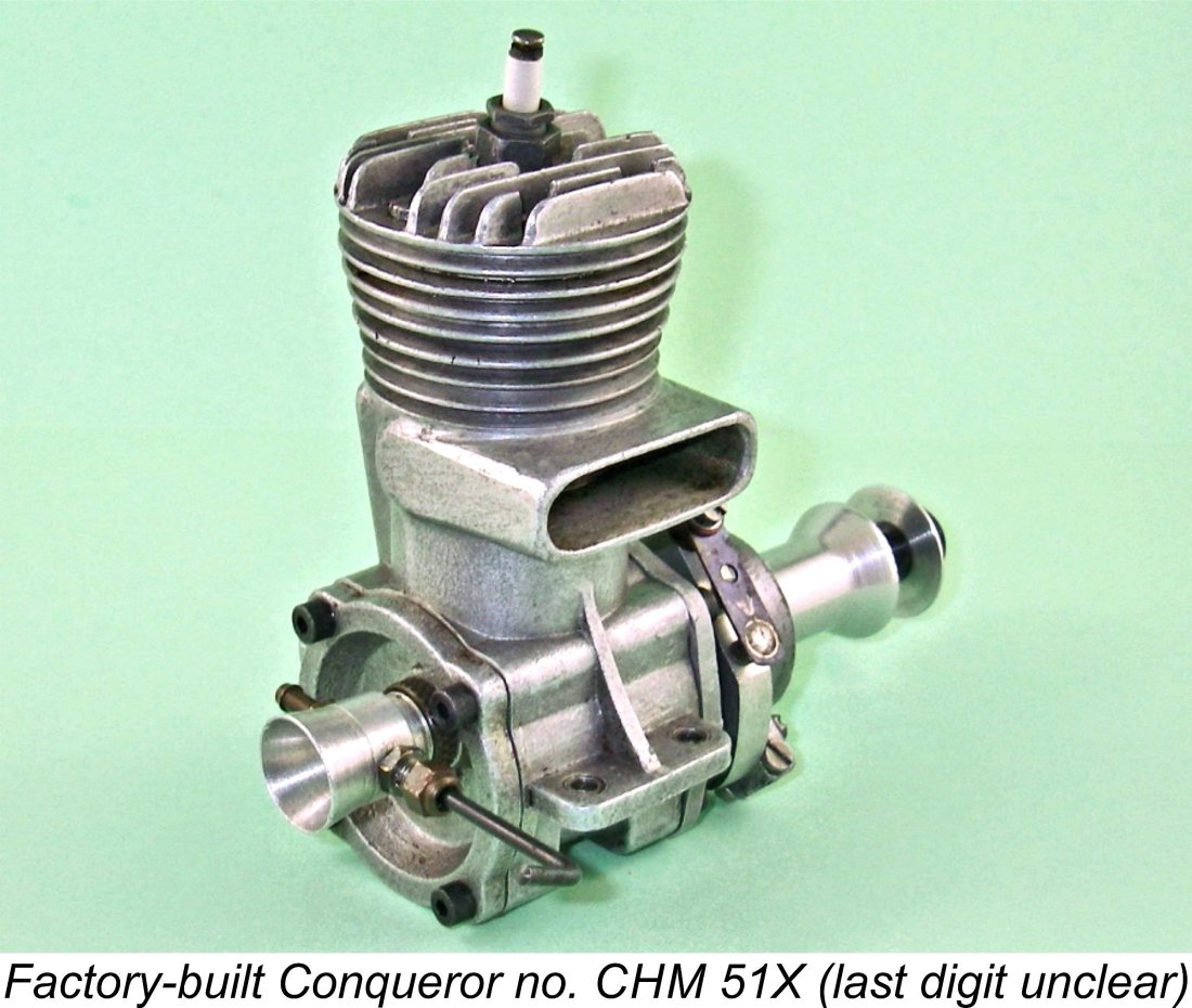
The downdraft Mk. IV backplate seems to imply that the later development of the Conqueror was far more influenced by Dooling than by McCoy or Westbury. A further indication of this is the fact that a one-off prototype bulge-bypass model of the Conqueror was reportedly tested just prior to the Company going out of business. Factory-built examples of the Conqueror may be recognized by the fact that they are serial-numbered. In addition, most of them display the stamped-on letters CHM, the meaning of which is obscure. Oddly enough, the factory-built Mk. I engines were numbered beginning at 500, while the Mk. II models started at 200............ go figure!
Interestingly enough, Hugh's records show that home-constructed Mk. I and Mk. II Conquerors appear to exist today in very comparable numbers. My own previously-illustrated Mk. I example bears no serial number and hence must have been constructed from a kit. It is a credit to its unknown builder. The main issue with engines which were predominantly home-built from kits is that there tended to be quite a wide variation in quality given the differing levels of skill possessed by their builders. Alan Strutt told me that he had handled a number of examples of the Conqueror over the years. According to Alan, they had almost without exception been very poor in the compression department. The rings and liner blanks were supplied by the well-established firm of Wellworthy, who certainly knew their business. However, the liners were supplied as simple billets of centrifugally-cast iron which had to be machined from scratch by the individual builders, who also had to machine the pistons from raw castings to achieve a fit with both the liners and the rings. Even minor mistakes on their part could certainly account for some of Alan's observations. I It seems that no-one ever got around to actually testing the Conqueror to see how it performed by comparison with its Rowell and Nordec rivals, both or which were the subjects of published tests in the contemporary modelling media. Based upon the contemporary results sheets, the Rowell at least was undoubtedly a superior performer, although neither the Rowell nor the Nordec worked well in hydroplane service and the Nordec was an indifferent performer in cars also. Presumably the Conqueror's substantially lower selling price was a major factor in the attainment of such sales success as the engine achieved - it certainly wasn't any performance edge! Since the engines were intended for spur gear mounting, they were never supplied with a clutch. Oddly enough, neither of the Ten-Sixty-Six clutch units will fit a Conqueror (!?), although Rowell, Z.N. and Nordec all made clutches which would fit the rival 10 cc model. Conversion of the Conqueror from car to aircraft use was a very simple matter, involving nothing more than the fitting of a Nordec-style bobbin prop driver and sleeve nut in place of the flywheel and spur gearing. My own illustrated Mk. I engine was equipped in this manner as received.
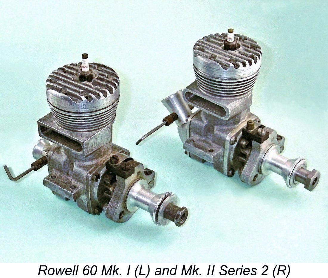
The Rowell 60 was another 10 cc racing engine primarily intended for car use which occasionally appeared in model aircraft service despite its rather excessive weight for that purpose, thus warranting inclusion in Warring's table along with the Conqueror and Nordec. Interestingly, the Oliver engines were not included, clearly being seen solely as purpose-built car engines during this period. How times were to change! Some readers may be surprised to see Ron Warring contributing to “Model Aircraft” on the subject of model engines. Most of us associate Peter Chinn with the engine articles in that publication, remembering Warring as the engine tester and commentator for the rival “Aeromodeller” magazine. It's true that Warring had started work with “Aeromodeller” magazine while still a teenager, but it seems that he was unable to get along with the owner of that publication at the time, D. A. Russell. For this reason, Warring greatly reduced his involvement with “Aeromodeller’, instead becoming a regular contributor to the rival “Model Aircraft” magazine while still contributing to “Aeromodeller” on occasion. It was only in 1952 after Russell severed his connection with “Aeromodeller” that Warring returned as the replacement engine tester for the departing Lawrence Sparey. With the above background in mind, we can now turn to a detailed examination of a representative product of the Ten-Sixty-Six company - the 10 cc Conqueror Mk. I spark ignition model. The Mk. I Conqueror - Detailed Description In presenting a description of this engine for my readers, I need to state at the outset that I’m necessarily speaking about a single example of an engine that was predominantly sold in kit form. Accordingly, significant variations may be expected between different examples, both in terms of construction details and quality of workmanship. Wherever possible, I have tried with the valued help of Hugh Blowers to point out details of my example which appear to depart from the "official" design of the engine.
Bore and stroke of the Conqueror are essentially identical to those shared by the McCoy, the Rowell and the Nordec at 0.937 in. (23.80 mm) and 0.875 in. (22.23 mm) respectively for a displacement of 9.89 cc (.603 cuin.). The stroke is identical and the bore is only three-thousandths of an inch smaller. This is almost certainly merely incidental - in all likelihood the bore and stroke were intended to be nominally identical. My example of the Mk. I Conqueror weighs in at 446 gm (15.73 ounces) complete with plug and timer - a fairly typical figure for a 10 cc spark ignition racing engine.
These figures appear calculated to produce good torque at moderate rpm, which may have been a desirable trait in engines intended primarily for car and hydroplane racing use. By contrast, the disc valve begins to open at a fairly conventional 45 degrees after bottom dead centre but then remains open until 60 degrees after top dead centre for a total opening period of 195 degrees! I would have thought that with the cylinder timing employed, a somewhat earlier closure without the sub-piston induction would have yielded better results....................
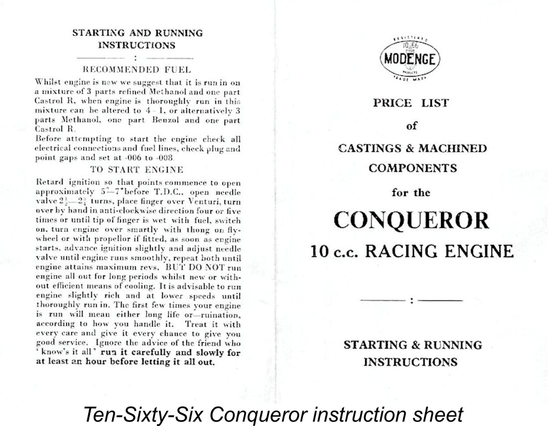
The specified compression ratio of the spark ignition Conqueror is unusually high for the period, being cited as 13:1, although a volumetric measurement of my own example gives a figure of 12:1 - still pretty high, and the engine certainly feels like it when flipped over! It's clear from this figure that the Conqueror was intended to operate on a pretty high-octane fuel. Indeed, reference to the manufacturer's instructions confirms that the engine was intended for operation on methanol-based fuels, even in spark ignition form. The rival Rowell 60, which was also intended primarily for car racing, and the The Nordec was also specified by the makers as a methanol-fuelled engine, but had to manage on a compression ratio of a mere 10:1, while the McCoy was set at 9.5:1. These somewhat lower compression ratios presumably allowed for operation on high-octane gasoline if desired, at least in their spark-ignition form. They are also more appropriate for operation on glow-plug ignition, particularly if a proportion of nitro-methane was to be added to the fuel - the absence of direct control over ignition timing would make me most hesitant to try to run a Conqueror leaned-out on glow-plug unless steps were first taken to lower the compression ratio somewhat. It's possible that the glow-plug versions of the Conqueror did in fact have lower compression ratios, otherwise pre-ignition might well have become a serious problem.
OK, let's take a closer look at this engine. On first acquaintance, the Conqueror presents itself as a well-proportioned and entirely conventional racing engine of its day, featuring the usual combination of rear disc valve induction, surface jet needle valve assembly, detachable front and rear crankcase covers, twin ball-race crankshaft, bobbin prop driver with sleeve nut for prop attachment, cross-flow loop scavenging and a lightweight ringed alloy piston. This was pretty much the standard racing engine formula of the period. This example of the engine immediately impresses one as being constructed to an extremely high standard. There's no trace of play in any of the bearings, for example. Compression seal is not perfect but is very good for a seemingly little-run engine which has not had the opportunity to bed down the rings. Base compression is outstanding.
So much for what can be learned from an external examination of the engine. To learn more, we have to take it apart. The first stage in doing this is the removal of the cast aluminium alloy backplate, which is fixed in place by four substantial 4BA slot-head steel screws. The backplate spigot is a snug fit in the bore of the crankcase but comes out easily enough. We note that the builder did not rely upon metal-to-metal fits here but used a well-cut paper gasket to ensure a good seal. The 4BA screws are of interest in that the plans actually specified 6BA fasteners. However, Hugh Blowers advises that all of the factory-built units with which he is familiar have 4BA screws. It can't be denied that this size seems far more appropriate for a 10 cc racing engine. That said, Hugh reminds us that supplies of hardware items such as machine screws were highly constrained in late 1940's Britain. Accordingly, engine The intake venturi on this example is a screw-in item along McCoy lines and appears to be secured on a tapered pipe thread, perhaps with some kind of thread-locker for good measure - I couldn't shift it by fair means and therefore decided to leave well alone. Interestingly, the plans specify a normal 7/16 BSF thread with a knurled brass locking ring, so once again this is a builder modification. The venturi on this example has an internal diameter of 0.325 in. (8.25 mm) - a bit on the conservative side for a 10 cc racing engine, especially when compared with the 0.417 in. (10.60 mm) diameter of the McCoy 60 Series 20 component, although it more or less matches the throat diameter of the unmodified Hornet 60. The intention was presumably to create sufficient suction to allow for the operation of the engine without the need for pressure fuel feed. In other areas, there's evidence of some very clear and original thinking with respect to the rotary valve design! Firstly, the designer avoided the common contemporary error of using an alloy rotor running against the alloy backplate. Such a combination does not wear well in service. The rotor in the Conqueror is a composite affair built up around a thin working disc of steel which runs directly against the backplate. Steel working against alloy is an excellent combination which beds down very effectively and wears extremely well.
The use of a steel disc running directly in contact with the backplate material was very much a Westbury trait - it was also used in the companion 5 cc Ten-Sixty-Six Hawk and Arrow models, which were the final efforts of the company in that displacement category. It's a very effective design approach which others might have done well to copy! It's worth noting in passing that the company's 5 cc efforts appear to be far more overtly Westbury-influenced than McCoy-inspired, presumably reflecting their somewhat earlier genesis. Back to the Conqueror: the mounting system used for the disc valve is also of great interest. The imperatives here are to provide a very secure mounting for the disc and also to incorporate some means of adjusting the clearance between the disc and the face of the backplate. Being unable to determine which (if any) threads were left-handed here (and logic suggested that the spindle thread at least should be left-handed), I elected not to disturb this set-up, especially given that the disc was perfectly adjusted as-is. However, Hugh Blowers has very kindly clarified this matter for us.
One would logically expect the thread for the disc spindle and its locking collar to be left-handed to avoid any tendency for the spindle to unscrew if the locking collar became loose when the engine was running. Such a failure could have catastrophic results as the spindle fouled the con-rod! However, the system adopted should be perfectly dependable even with the use of a right-handed thread - the only requirement would be to periodically check that the collar remained tight. Overall, a very neat and effective approach to the design of this assembly.
The result is a counterbalance having a rather unusual "straight-across" configuration. I thought at first that this might have been an approach taken by the home-builder who made this particular engine in his own way, rather than a factory arrangement. However, Hugh Blowers reports that the factory-built engines use the same type of counterbalance, implying that this is the standard design approach.
But there's also a fine adjustment which does not require timer removal. The points are mounted on a separate cast arm which is pivoted at one end on the main timer casting and is secured at the other end by a set screw which acts through a short crescent-shaped slot. By loosening the set screw and rotating the point mounting arm on its pivot, a degree of point gap alteration can be achieved. Once again, very neat indeed! A point gap of .006 in. to .008 in. was recommended by the manufacturers. The shaft is mounted in two ball races with a bronze bushing inserted into the casting between the races - a quality touch which is clearly intended to create a long-lasting gas seal around the main journal. The cam is formed in the surface of the main journal between the ball races. The prop driver on this particular example is more or less a clone of that used on the Nordec R10 racing engine, with a steel sleeve nut of standard form being used to secure the propeller. I elected not to remove the shaft given the tightness with which all of the front end components were assembled, but I doubt that we'd learn much more from doing so anyway. Interestingly, Hugh Now it's off with the cylinder head. This proves to be secured by six 5BA steel slot head screws. The plans apparently specified 6BA screws, but the builder of this particular engine clearly did not consider such a thread to be adequate for a 10 cc racing engine. I'd best not lose these screws - 5BA items aren't that easy to find these days!
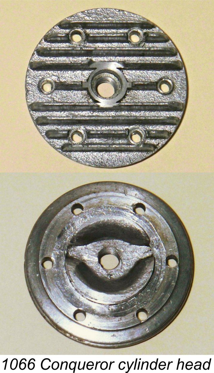
The slight angle at which the plug is set is only one of the oddities connected with the installation of this essential component in the particular example of the engine under discussion. The plug hole is threaded ¼-32 in the usual way, and the thread length is suitable for a long reach plug. So far, so good, but now it gets a bit weird! The seat for the plug where the copper sealing gasket rests is deeply recessed into a spigot cast into the top of the head, visible in the above image at the left. This recess has a diameter of only 0.340 in., which is insufficient to accommodate the body of the long reach Champion VR2 spark plug or equivalent that one would normally expect to find in use on this engine. The integrally-cast spigot has an outside diameter of only 0.435 in., so it appears that a recess diameter of this order was actually envisioned by the designer - there's insufficient meat for much more. A Champion V3 plug fits fine but is a little short in term of reach, while the rather rare British-made Lodge plug with which this example is equipped is also a good fit but is even shorter in terms of its reach. Still, plugs of this size must have been the intended items. Unless the correct plug is fitted, compression seal will doubtless feel a little suspect. This too appears to be a quirk of my particular example. Other examples of the spark ignition Conqueror do not feature this recess, allowing the fitting of more or less any desired spark plug. However, the glow-plug versions evidently do feature the recess. Once again, our unknown builder seems to have been ploughing his own furrow here! The mating surface of the head is nicely machined around the combustion chamber periphery, and there's a thin soft aluminium shim between the head and the top of the liner. Presumably shims of differing thicknesses (or multiple shims) could be installed to fine-tune the compression ratio. It's also noteworthy that the annular cooling fins on the edge of the head are very accurately formed so as to blend in seamlessly with those on the main cylinder barrel - with the engine assembled, the joint between the head and the barrel is almost undetectable! For the curiously-inclined, it's at the lower surface of the second cooling groove down (the uppermost of the three half-depth cooling grooves - see the front view above).
With the head and front housing off, it's now possible to remove the piston assembly through the top of the liner. The lightweight alloy piston proves to be very similar to its McCoy equivalent, with a high contoured crown which incorporates a baffle. The piston features two skirt ports on the transfer side which align with two holes in the lower cylinder liner at bottom dead centre, thus aiding the bypass process as well as promoting improved piston cooling and lubrication.
The liner appears to be shrunk in and could not be shifted by fair means. I therefore elected not to disturb it, but was able to confirm that the finish of the bore is extremely good. The transfer port is divided into four adjacent square openings of moderate size separated by the usual thin columns of metal to prevent ring snag, while the exhaust port consists of six somewhat larger apertures arranged similarly. The liner is also provided with the previously-mentioned additional openings on the transfer side which align with the piston ports at bottom dead centre. The liner is machined from a billet of centrifugally-cast iron. So there it is - the Ten-Sixty-Six Conqueror Mk. I revealed in all its glory! The engine went back together without complications, and was once again all ready to show its paces if desired. I'd expect a performance quite similar to that of the contemporary Nordec R10 Mk. I model, based on the very parallel design features of the two units. I would however advise against anyone giving this engine a lot of leaned-out running on glow-plug ignition, particularly at lower speeds - the compression ratio is such that pre-ignition would be more or less guaranteed, with consequent potential for damage to this very rare unit. If I were planning to run it hard over a period of time (which I'm not!), I'd either reduce the compression ratio (thus sacrificing the perfect matching of the head and cylinder jacket fins) or use spark ignition with the manufacturer-recommended methanol fuel. One final comment is worth making at the conclusion of this descriptive portion of the article. This particular example of the engine is outstandingly well made in all respects, comparing very favourably with the standard of construction of other competing models such as those manufactured commercially by the likes of Nordec and McCoy. If this is an example of a home-built model constructed from castings and materials (as it appears to be), then it is an eloquent testament to the skill of its unknown constructor - a real Motor Boy of the 1940's! I wish I knew his name ................... The Conqueror on Test
As before, despite my previously-stated reservations I elected to do this using glow-plug ignition since this would allow me to start the engine by hand (I don't own an electric starter, which is pretty well essential for starting a high-speed fixed-timing sparkie)! Mindful of the very high compression ratio, I used a low-nitro fuel (5% - the lowest that I had on hand) with plenty of castor oil in the mix, also fitting a short-reach plug. The intent of the latter measure was two-fold - first, to reduce the compression ratio just a fraction; and second, to retard the full involvement of the fuel charge by placing the plug element in a recess, thus hopefully reducing the ignition shock loads on the working components. These measures were entirely successful in that the engine started very easily by hand using my usual big-bore "reverse-bounce" technique - set the prop at "ten past eight" with the piston at bottom dead centre, administer a healthy prime and then HIT the prop backwards from the bottom dead centre position with the plug activated. The inevitable backfire almost always starts the engine in the correct direction. As before, the Conqueror ran as smoothly as one could wish, showing no signs of pre-ignition at any time. Mind you, I only leaned it out briefly on each prop tested, just long enough to get some idea of the performance levels available while keeping it on a fast four-stroke the rest of the time. I also kept the brief leaned-out speeds above 11,000 RPM. As before, compression seal proved perfectly adequate for a start and actually improved even further over the course of the 15 minutes or so of additional running time that the engine received. The earlier impression that this example had been previously run very little, if at all, was strongly reinforced - the rings appeared to be still bedding in.
These figures are actually superior to Peter Chinn's reported figures for the original Nordec RG10 of 0.63 BHP @ 12,200 rpm. As mentioned earlier, the setup of this particular example of the Conqueror has been modified from stock specification by the builder - those modifications plus the 5% nitro may have had a positive effect upon peak output. The very conservative cylinder port timing figures probably explain the engine's relatively low peaking speed. However, before we get too excited let's recall that my own tests on the contemporary Rowell 60 Mk. I yielded a peak output of some 1.08 BHP @ 13,300 RPM. Moreover, the "parent" 1946 McCoy 60 black-case model reportedly delivered over 1.0 BHP @ 13,000 rpm, while the McCoy 60 Series 20 which appeared shortly after both the Conqueror and the Rowell developed over 1.5 BHP at speeds in excess of 16,000 RPM. Considering these figures, it becomes immediately apparent why neither the Conqueror nor the Nordec could get anywhere near the McCoy (or for that matter the Rowell) in competition terms. With more nitro, the engine would doubtless improve, but not to the point of becoming truly competitive. The engine has now survived some thirty minutes or so of running in my hands, emerging completely unscathed with no signs of play developing anywhere and no tendency for anything to work loose. At the end of the second set of test runs, compression seal was further improved, no doubt due to the rings bedding down a little more. I'd have no hesitation in running it again if the occasion ever arose. Conclusion I hope that you've enjoyed this detailed look at one of the least-remembered British racing engines of the early post-WW2 period. After a long period of more or less complete neglect, there are clear signs that interest in the Conqueror and other Ten-Sixty-Six products is very much on the rise - presumably the fact that the predominantly aero-minded engine collector community is becoming increasingly aware of the marque has something to do with this. Hugh Blowers told me that twenty or more examples of the Conqueror had been offered for sale over the few years prior to 2022. So the engine is "back in circulation" and anyone interested may in time find an opportunity to acquire one. I’m sure that no classic racing enthusiast who does so will be disappointed! If anyone out there is able to add to our collective knowledge of these relatively rare engines, please get in touch! As always, any additional information will be openly and gratefully acknowledged. _____________________________________ Article © Adrian C. Duncan, Coquitlam, British Columbia, Canada First published on MEN December 2011 This revised edition published here October 2022 |
 One way or another, perhaps through reading Sellar and Yeatman's classic tongue-in-cheek book "
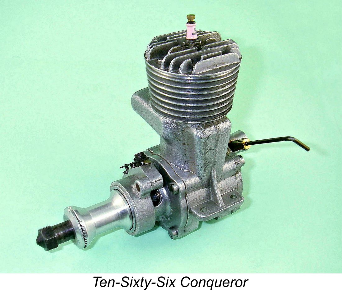 I also wish to pay tribute to my English correspondent Alan Strutt, from whom I acquired the pristine example of the Conqueror which appears in this article and who was kind enough to provide me with some background information regarding this rare and hitherto rather obscure motor. Finally, I'm most grateful for the invaluable assistance of my friend Kevin Richards, who responded to a number of requests for information during the preparation of this article.
  My
My 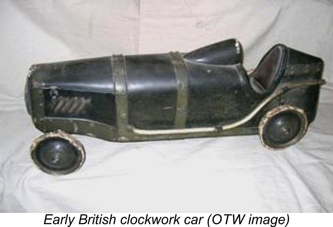 Oddly enough, it was the advent of WW2 that triggered the emergence of interest in I/C-powered model car racing in Britain. Up to that point, car racing in Britain had largely been confined to clockwork and rubber-powered models, although a few I/C powered models had appeared. The factor that prompted a major change was the official wartime ban on the flying of I/C-engined model aircraft. Probably just as well - flying models would very likely have been shot down by enthusiastic A/A or Home Guard personnel!
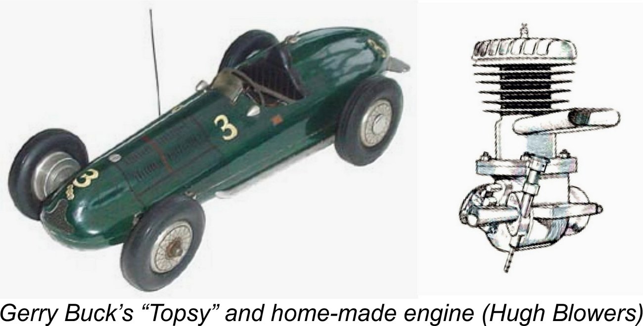
 Hornet-influenced design remained one of the engines to beat for some years after the conclusion of the war, powering his car "Topsy" in 1948 to the first 100 mph speed recorded in Britain. Ken Robinson’s
 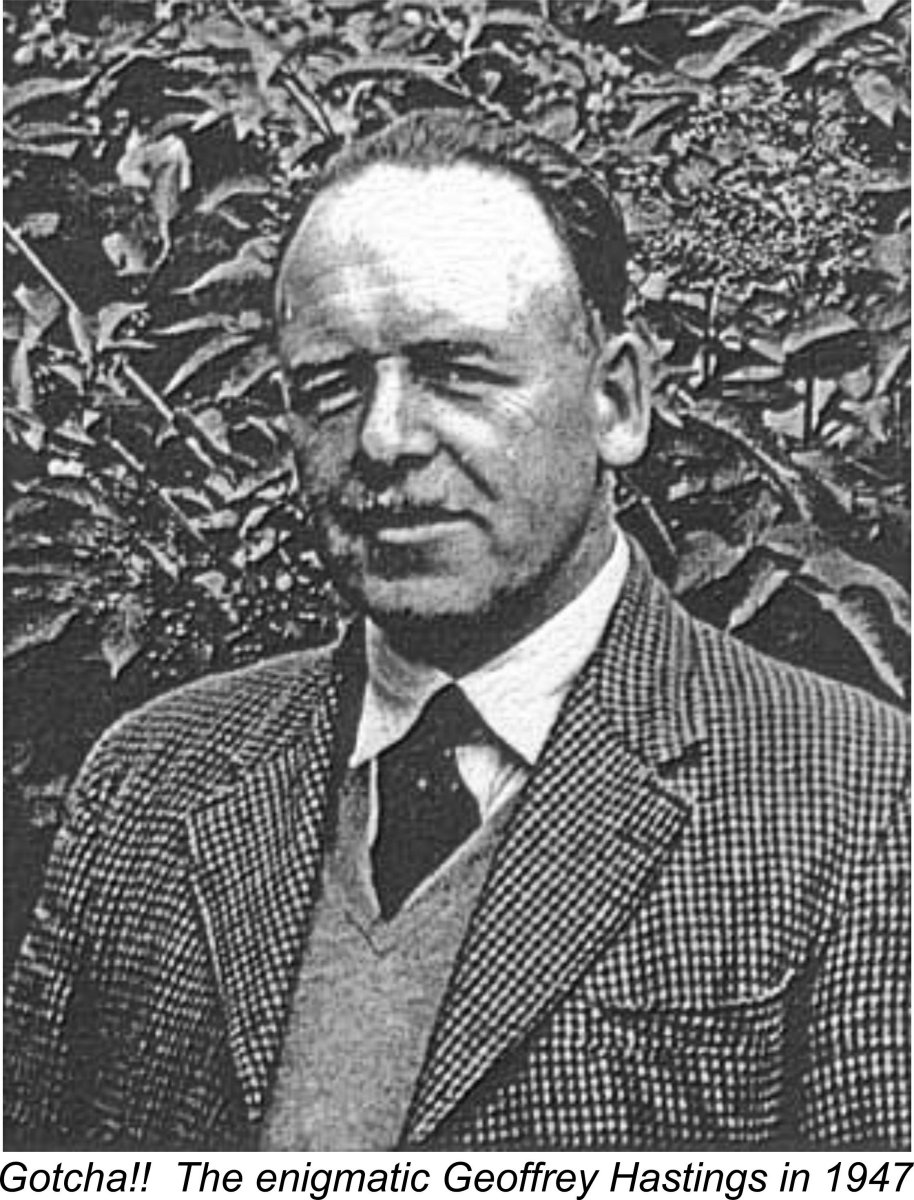 The Ten-Sixty-Six venture was one of the pioneering British commercial model car initiatives, being founded in late 1945 by then 38-year old Geoffrey Irving Hastings (1907-1957). No prizes for guessing the inspiration for the 1066 company name! Hastings was born in April 1907 in Nelson, Lancashire to Sydney and Annie Hastings, who were both weavers in the many cotton mills which then dominated the district.
 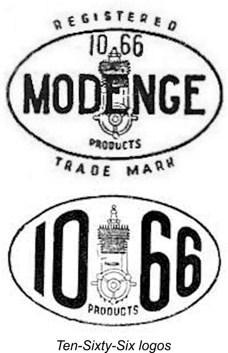 From the outset, the activities of the Ten-Sixty-Six company were centred primarily upon the field of model car racing, although they were also involved with tethered hydroplanes. They traded under the name Ten-Sixty-Six Products, using several different registered trade-marks, all of which were based upon an oval cartouche.
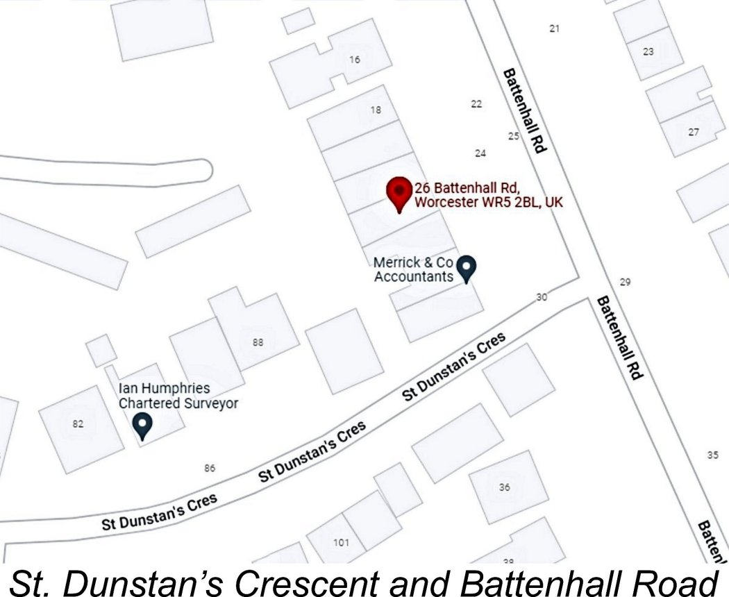

 The advertised range of items offered by Ten-Sixty-Six was quite extensive - apart from the model engines themselves, a complete line of parts and accessories required to build and operate tethered model racing cars was also produced. In addition, there were two model car kits as well as a tethered hydroplane kit which was available in two sizes. These products were initially sold exclusively through dealers, but as of March 1948 the company took to selling directly to the public from its Worcester premises.
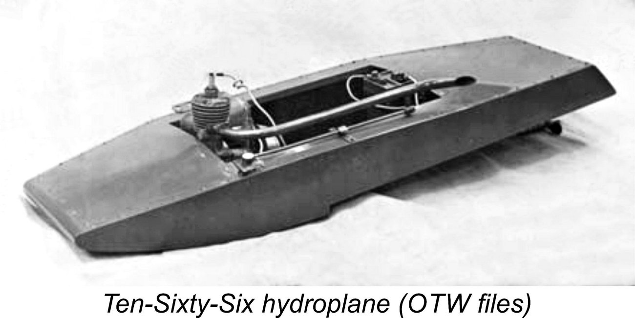 The hydroplane offered by Ten-Sixty-Six also displayed strong Westbury influence. It featured a single-step hull looking a lot like Westbury’s famous “Golly” design of the 1930’s - indeed, it may well have been designed by Westbury. This kit was offered in two sizes for either 5 cc or 10 cc engines. By mid 1940’s standards, it couldn’t really be considered a seriously competitive design.
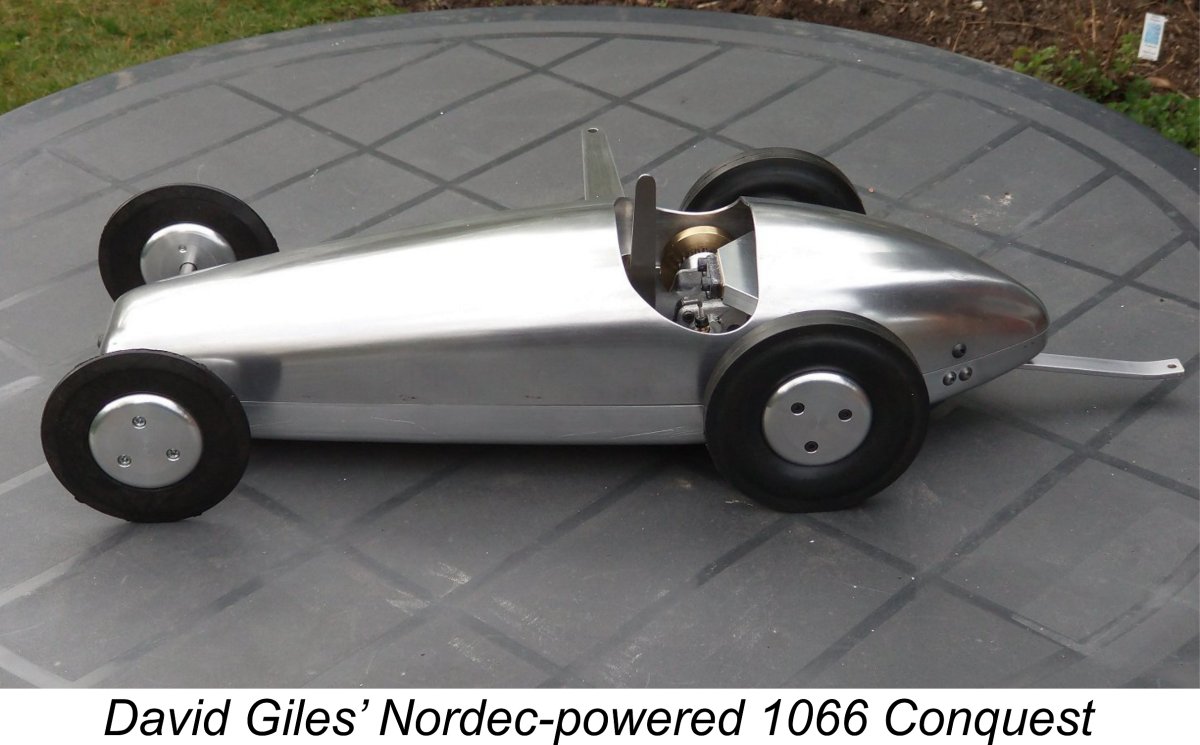
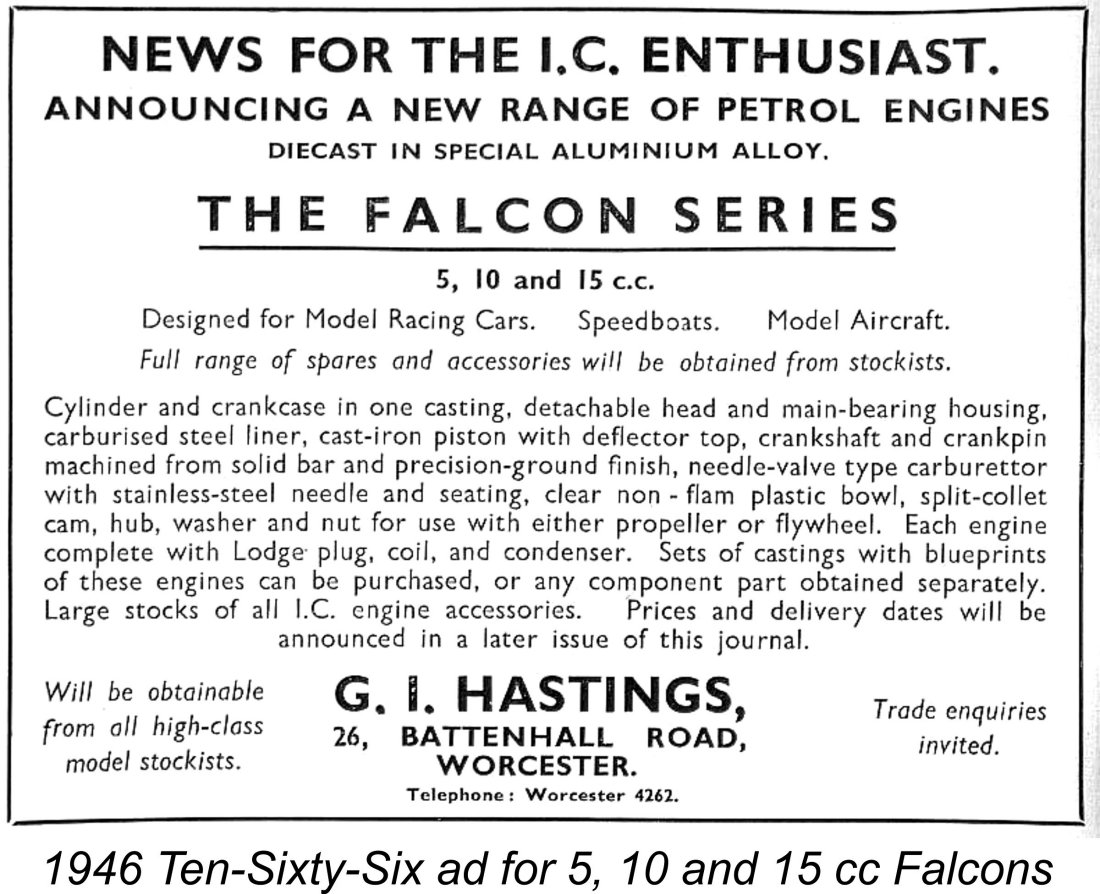 subject, the Conqueror 10 cc RRV model. The company also flirted with a 10 cc version of the side-port Falcon, which was briefly advertised alongside the 5 cc model. However, surviving examples of this variant appear to be extremely rare these days - I've certainly never encountered one personally, although I know of one or two examples owned by others. There was also an early advertising reference to a 15 cc version as reproduced at the left, but there's currently no hard evidence that this variant ever actually existed.
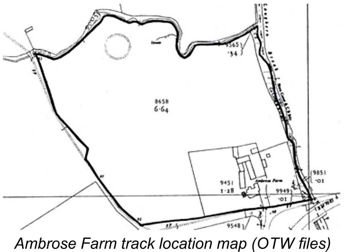
 With the sole exception of the 5 cc Hawk RRV model, all Ten-Sixty-Six engines were available in kit form for home building. This was doubtless a reflection of Edgar Westbury’s influence on the company’s direction. All well and good, but the focus on home construction had the effect of greatly diminishing the appeal of the Ten-Sixty-Six engines to the many modellers who lacked either the capacity or the inclination to construct their own powerplants, instead merely wishing to enjoy operating I/C-powered models of various types.
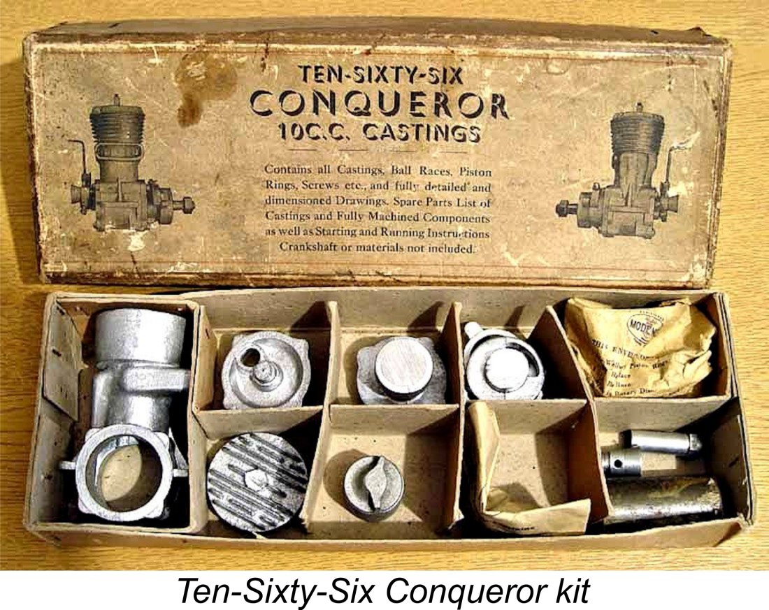
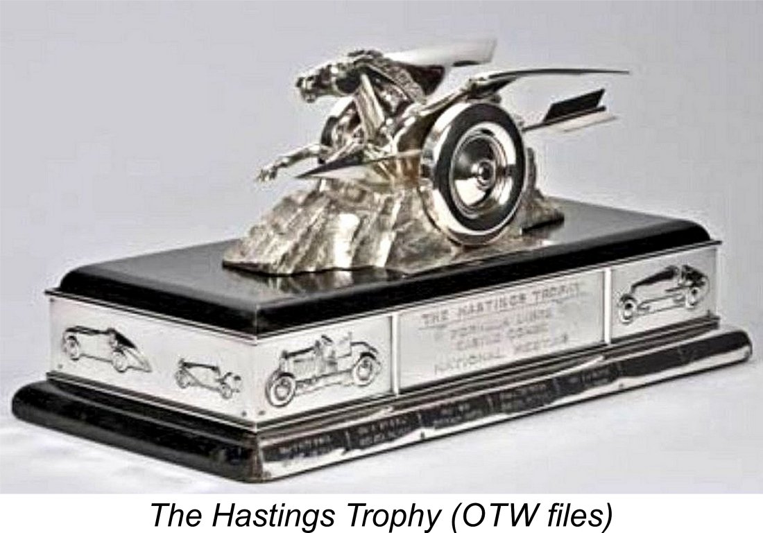 In 1948 Hastings introduced a very fancy-looking trophy reportedly costing more than £200 (not, I hasten to add, paid for with his own money!) together with a complex set of rules designed to encourage development of home-built model racing cars using British products. John Oliver was among those who featured in the results for 1948 and 1949, which were to be the only years during which the event was run. It's an often-overlooked fact that Oliver's chief interest in the early days was in model car racing - indeed, his famous Tiger 2.5 cc diesel began life as a purpose-built car engine.
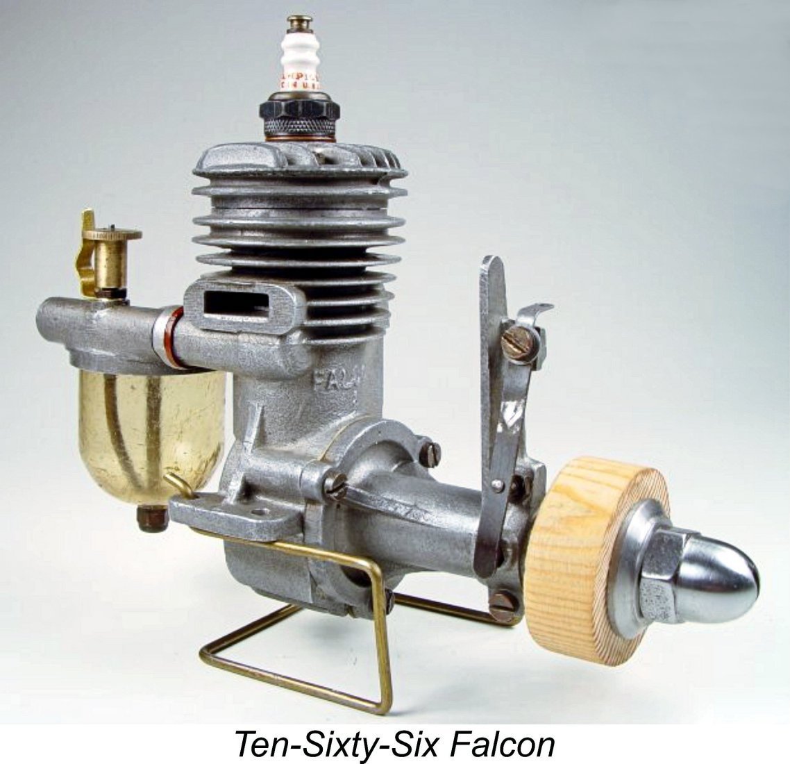 hand. He participated in a model aircraft meeting in the Midlands for which Hastings offered a first prize of a new Falcon motor. Ray duly won the event and was formally presented with his Falcon by Hastings directly.
 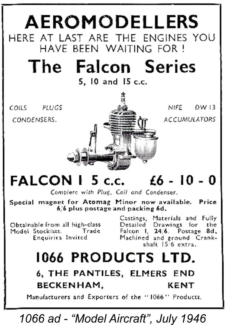 subsidiary interest in tethered hydroplane racing, to the point that they do not appear to have advertised on anything like a regular basis in the aeromodelling media of the day. Indeed, I have found no instance of their engines even being the subject of commentary in those media.
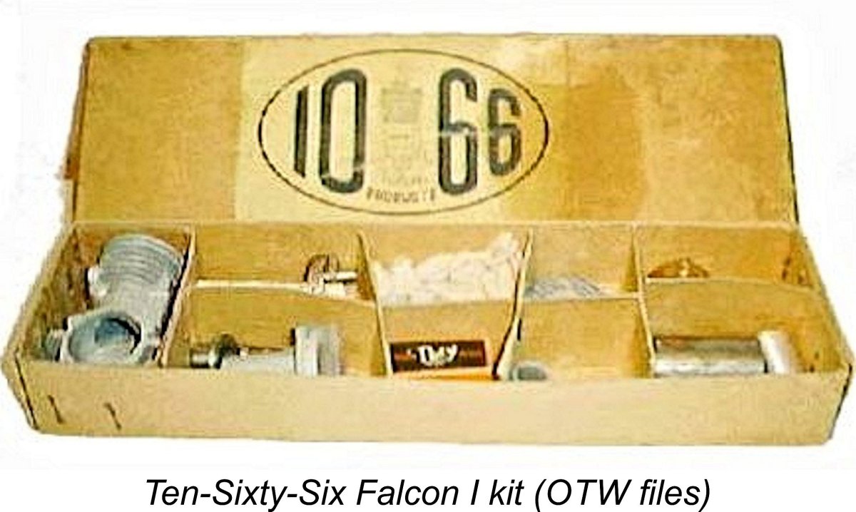
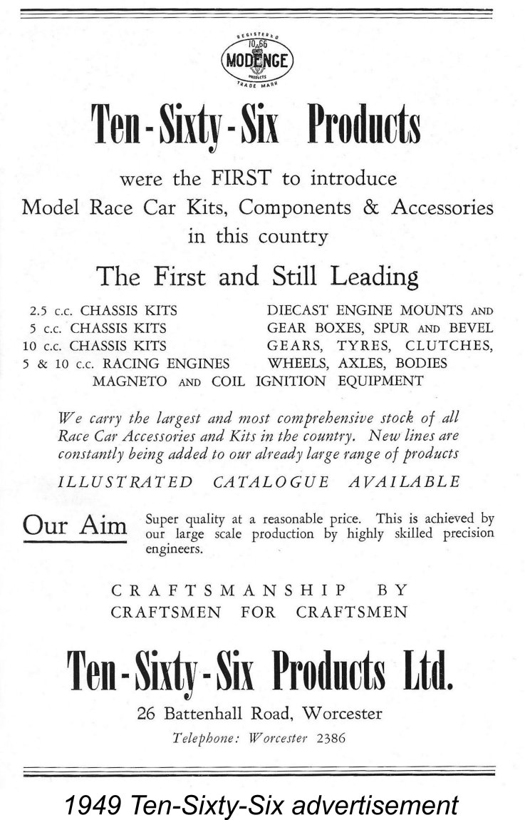 Recognizing this, the Ten-Sixty-Six company directed their main advertising efforts toward the precision craftsman fraternity. The late MEN Editor Ron Chernich undertook a scan through the advertisements in “Model Engineer” from 1946 through 1950. He found that Ten-Sixty-Six Products ads appeared regularly every couple of months, always in the front advertising section, all the way up to the final placement in July 1950 which is reproduced below. However, despite the unquestionably enthusiastic and sincere efforts made by Hastings to promote his venture, the company was clearly struggling as the 1940's drew to a close.
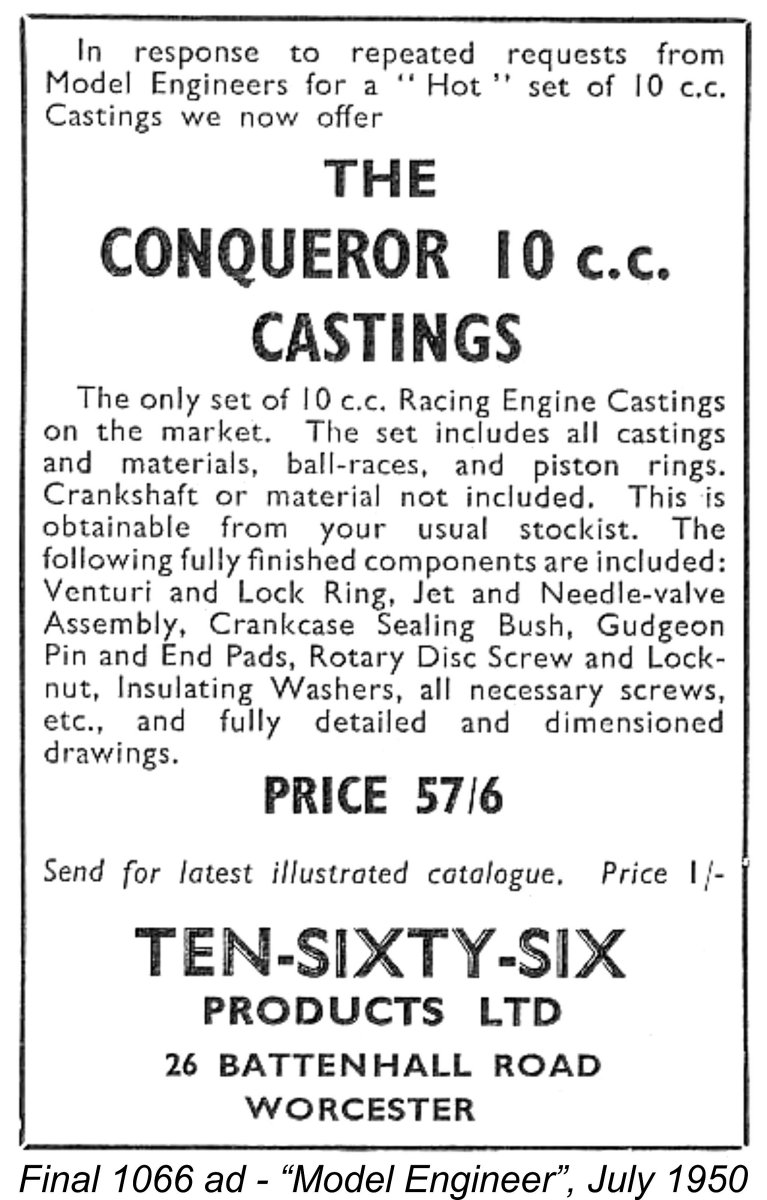 It was probably a combination of reasons rather than any single cause which led to the development of this unhappy situation. Apart from the early supply difficulties, the primary factor was likely the focus of the company upon the costly and technically-demanding sport of model car racing, to the virtual exclusion of all other interests. It can't be denied that model car racing at this level was an extremely expensive business by late 1940's standards. By the time a customer could bring a competitive 10 cc car to the starting line, for example, his investment in that single model might well be on the wrong side of £40, a small fortune in those days, being very roughly equivalent to some four thousand dollars in today's money.
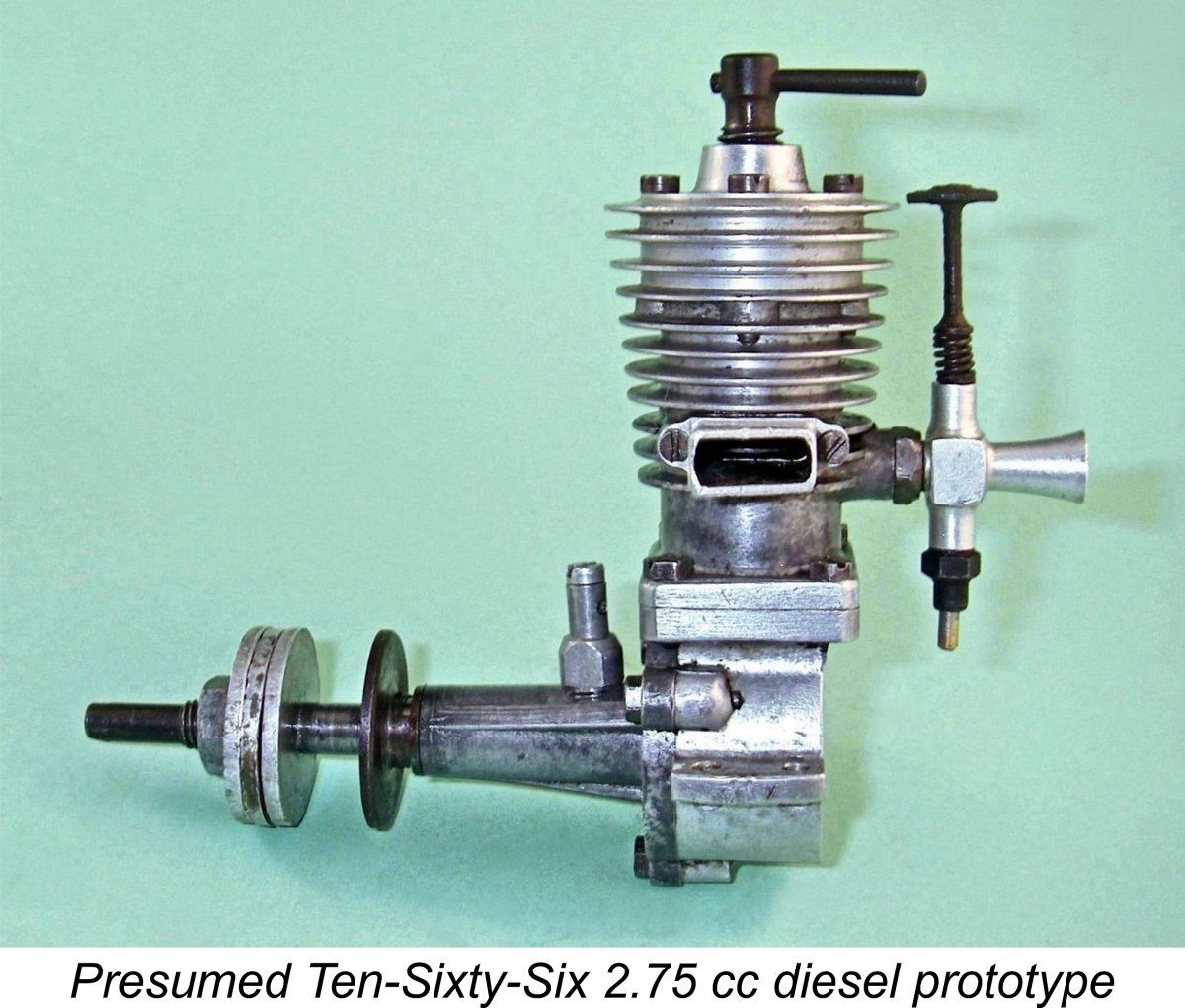
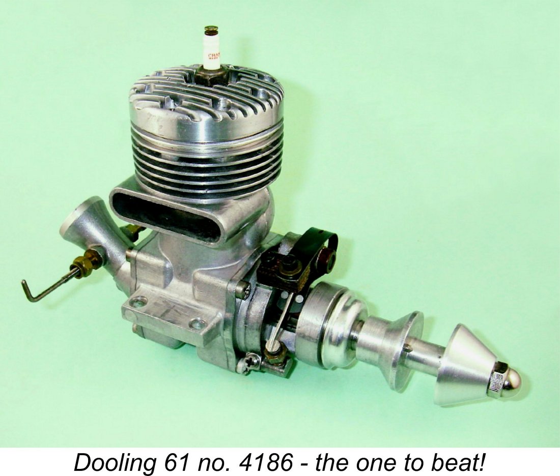 Quite apart from this, there was also the stark fact that the engines simply weren't good enough - the results sheets from the period make this abundantly clear. Edgar Westbury was at heart a designer of the 1930's, whereas by the late 1940's the mantle of racing engine design leadership had passed across the Atlantic to the likes of
 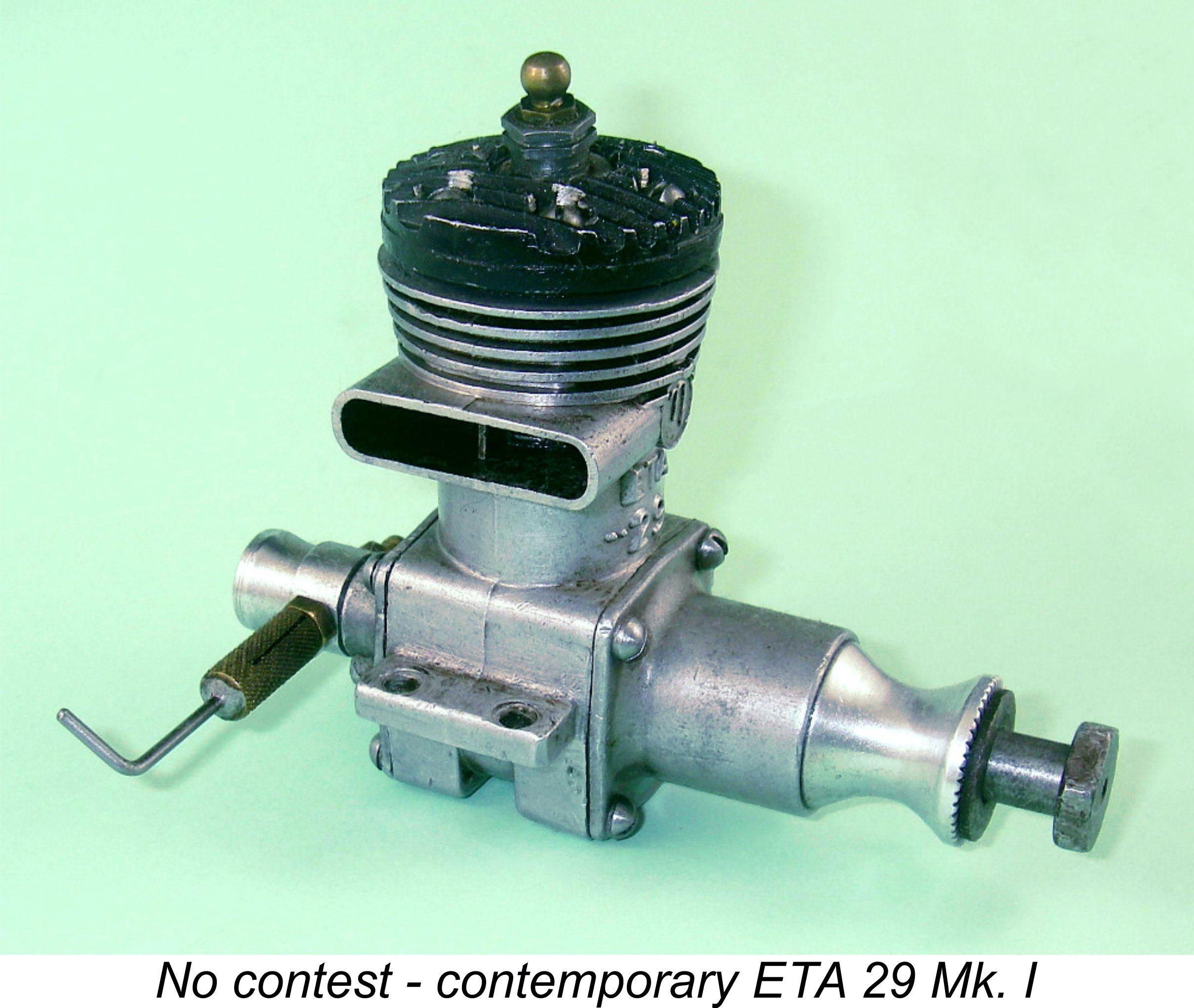 Things were no different in the 5 cc class, although the British
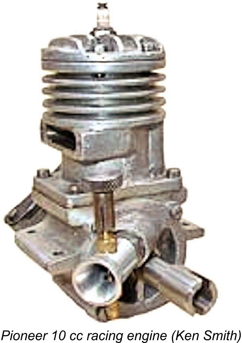
 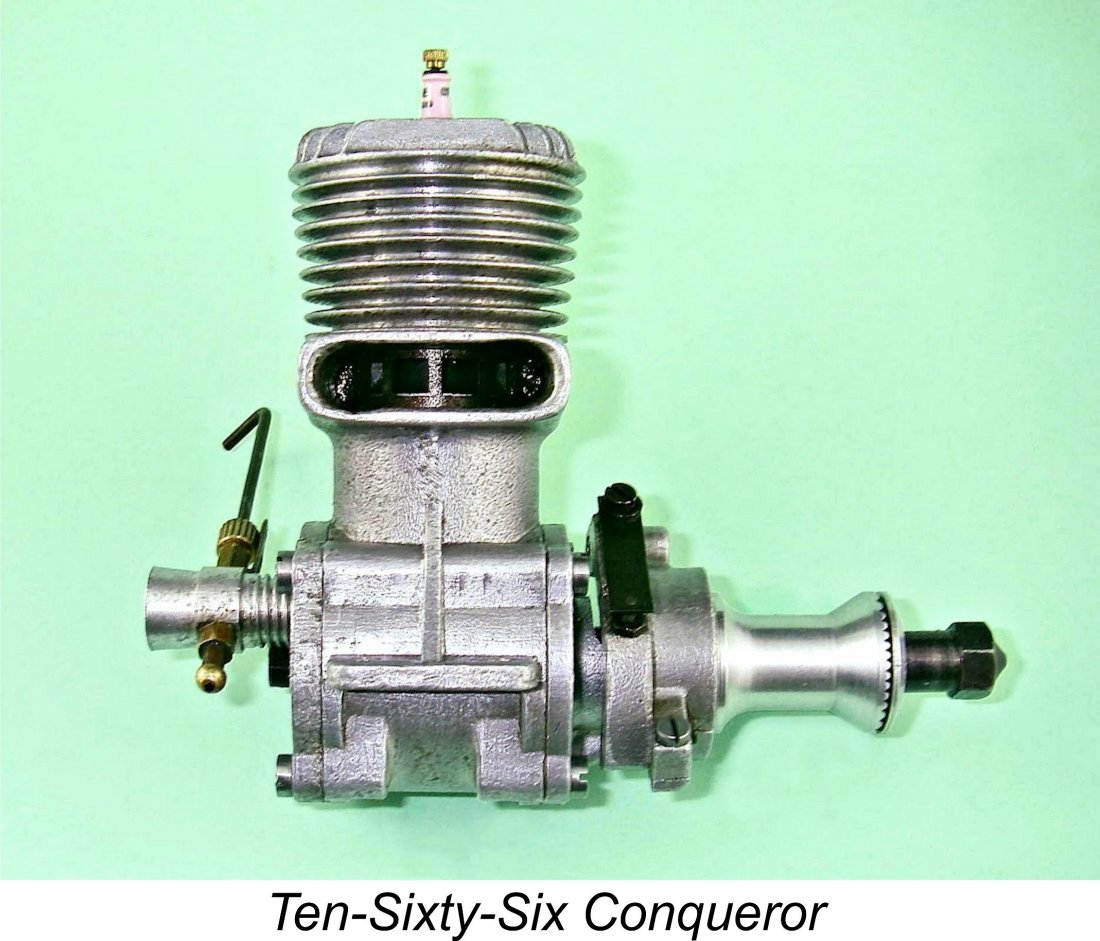 We must now return to 1948, at which time interest in model car racing and tethered hydroplane racing in Britain remained high, along with a growing interest in C/L speed flying. The 10 cc class was among the Blue Riband categories in all three branches of the power modelling hobby, causing several British commercial manufacturers to decide more or less simultaneously in 1948 to enter the "prestige" field of 10 cc model racing engine production. The North Downs Engineering Company of Whyteleafe, Surrey, launched their
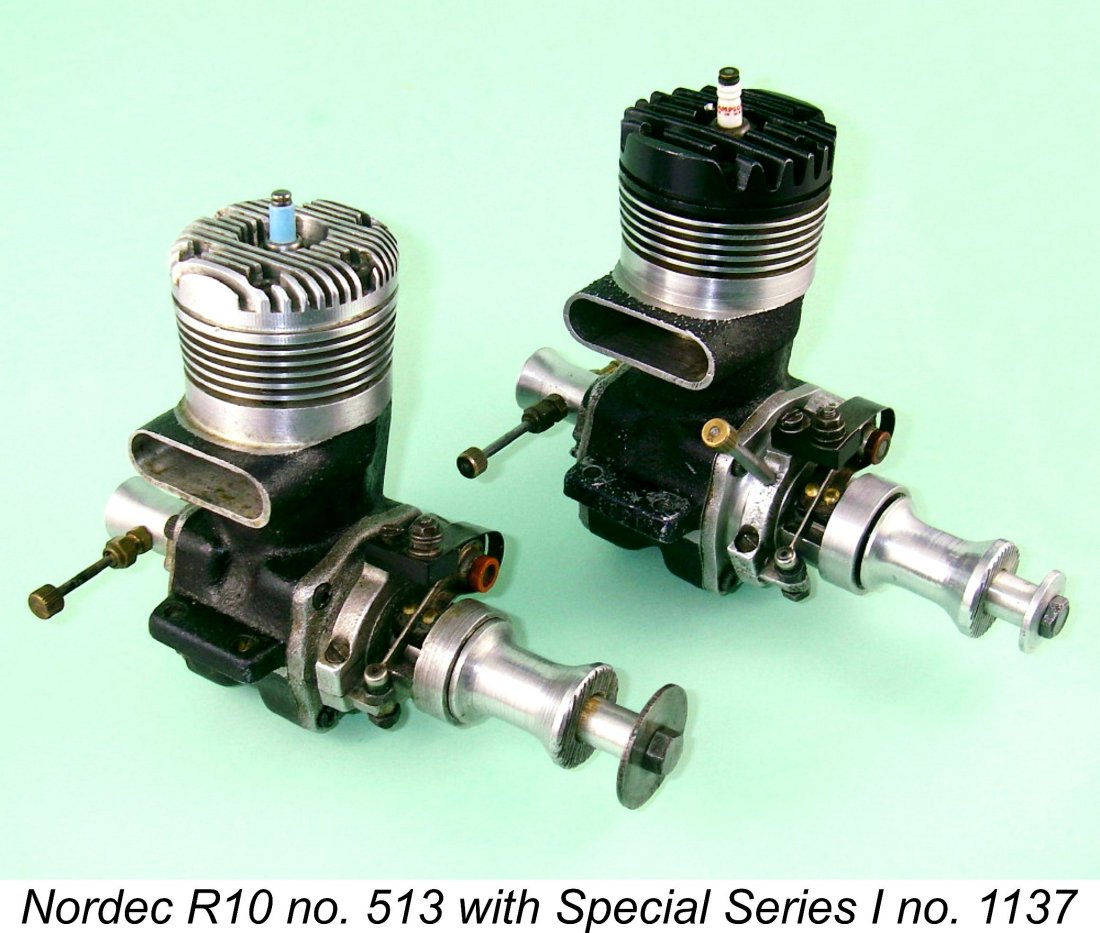
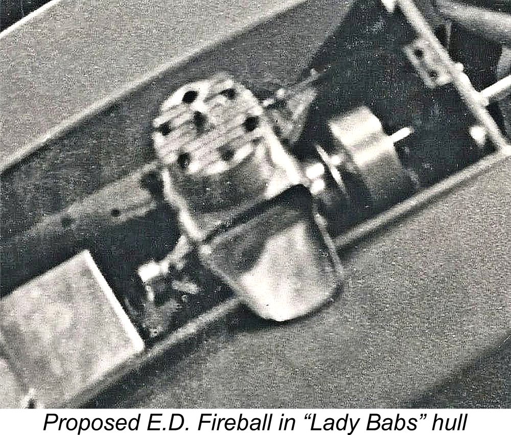 The other stillborn effort came from none other than a pair of individuals who were associated with the
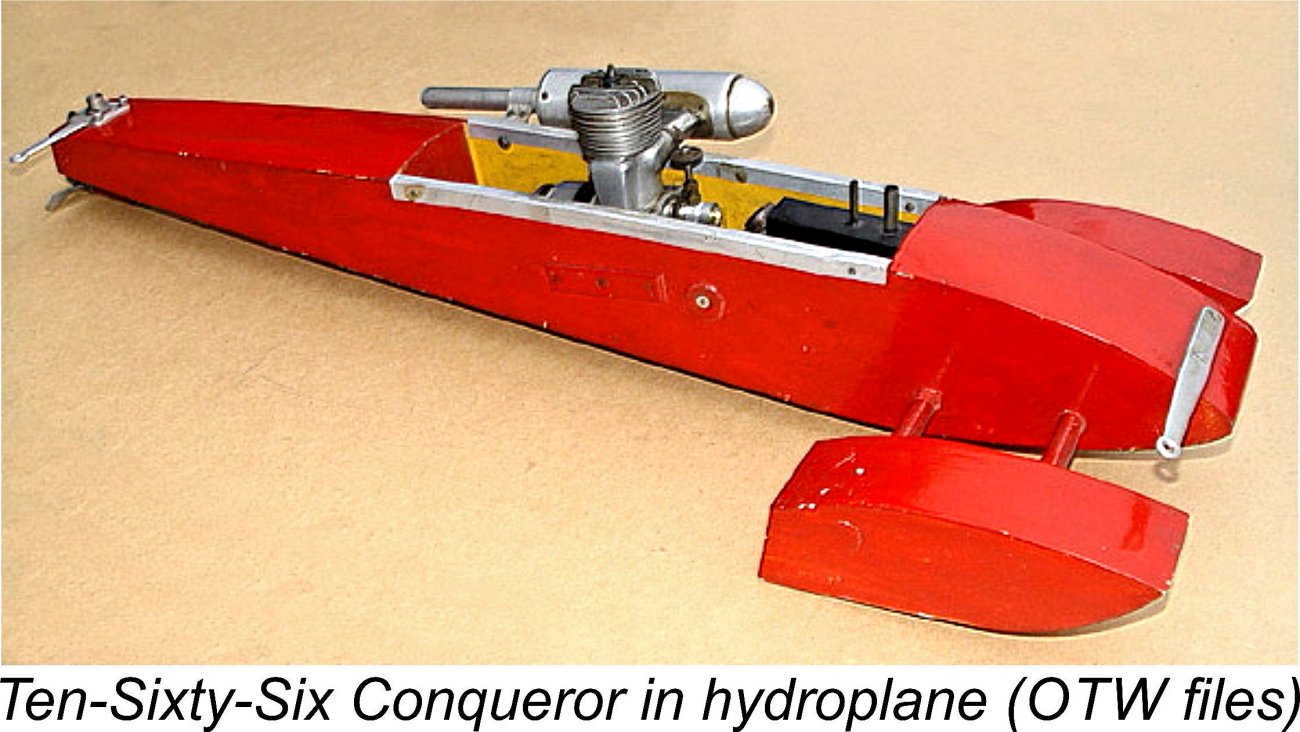
 n addition, the tendency towards poor compression may have been due simply to the engines examined by Alan being basically clapped out (car engines ingest a lot of dust, and the revs attained at start-up can be pretty spectacular!). Whatever the case, the illustrated little-run example is an exception to this rule, having quite acceptable compression despite not having been fully run in and the rings bedded down. It is in fact extremely well-fitted throughout.
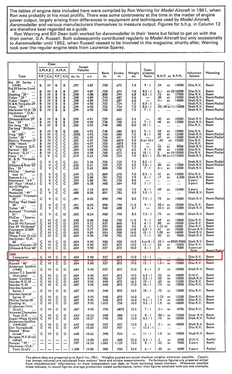 I am presently aware of only one reference which confirms that the Conqueror was recognized in its day as a model aero engine as opposed to being merely a car unit. This was the inclusion of the Conqueror (and its 5 cc relative the Hawk) in
 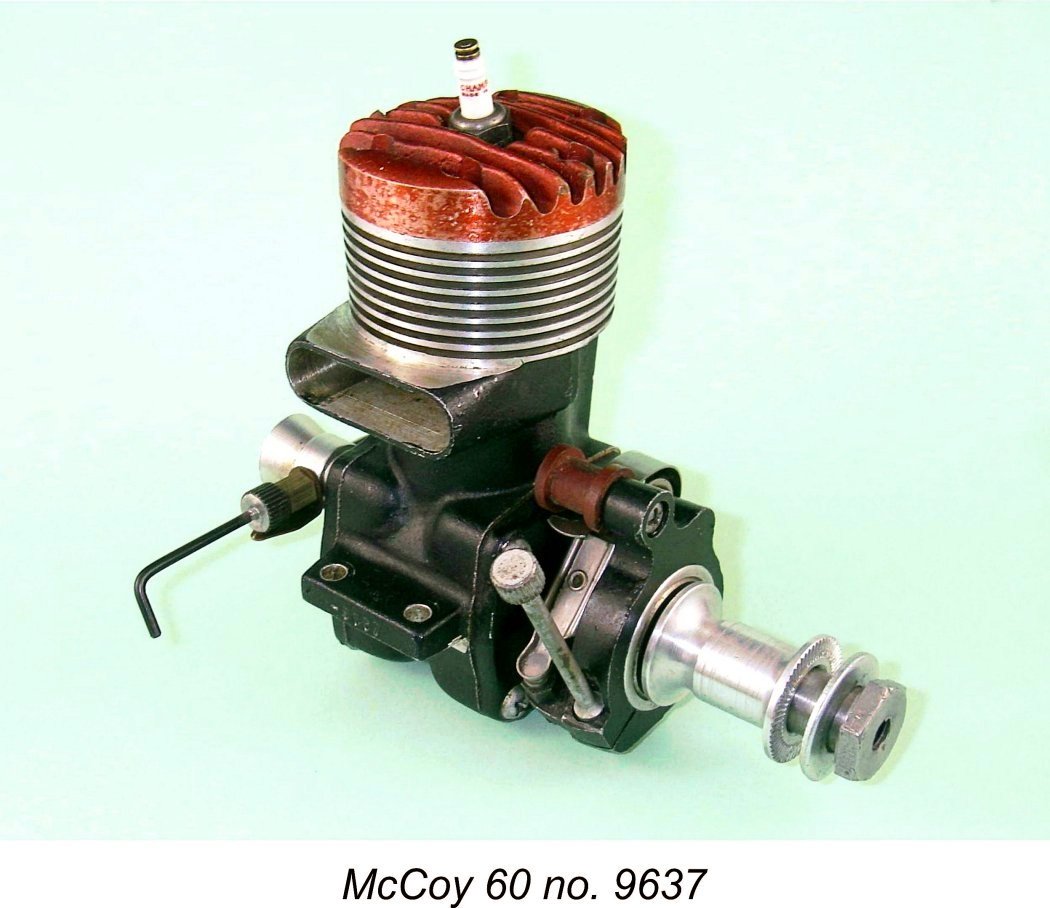 As one might expect for a 10 cc racing engine dating from 1948, the Conqueror is a fairly conventional design of its day, displaying a considerable degree of McCoy influence. Like the rival British-made 10 cc
 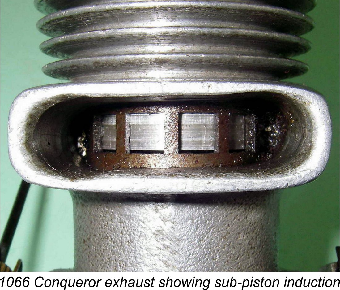 The timing of the engine is a bit weird - the transfer and exhaust periods are very conservative for a racing engine, while the induction timing is extremely aggressive. The exhaust opens quite late at 62 degrees before bottom dead centre for a total opening period of only 124 degrees. The transfer is timed even more timidly, opening at 51 degrees before bottom dead centre for a total opening period of 102 degrees and a blow-down period of some 11 degrees. There is also a very small period of sub-piston induction extending approximately 10 degrees each side of top dead centre. Hugh Blowers notes that none of the factory-built engines of which he is aware exhibit this latter feature, implying that it is due either to construction inaccuracies or to the builder's own ideas regarding set-up of the motor. A slightly over-length conrod would explain all of these observtions.
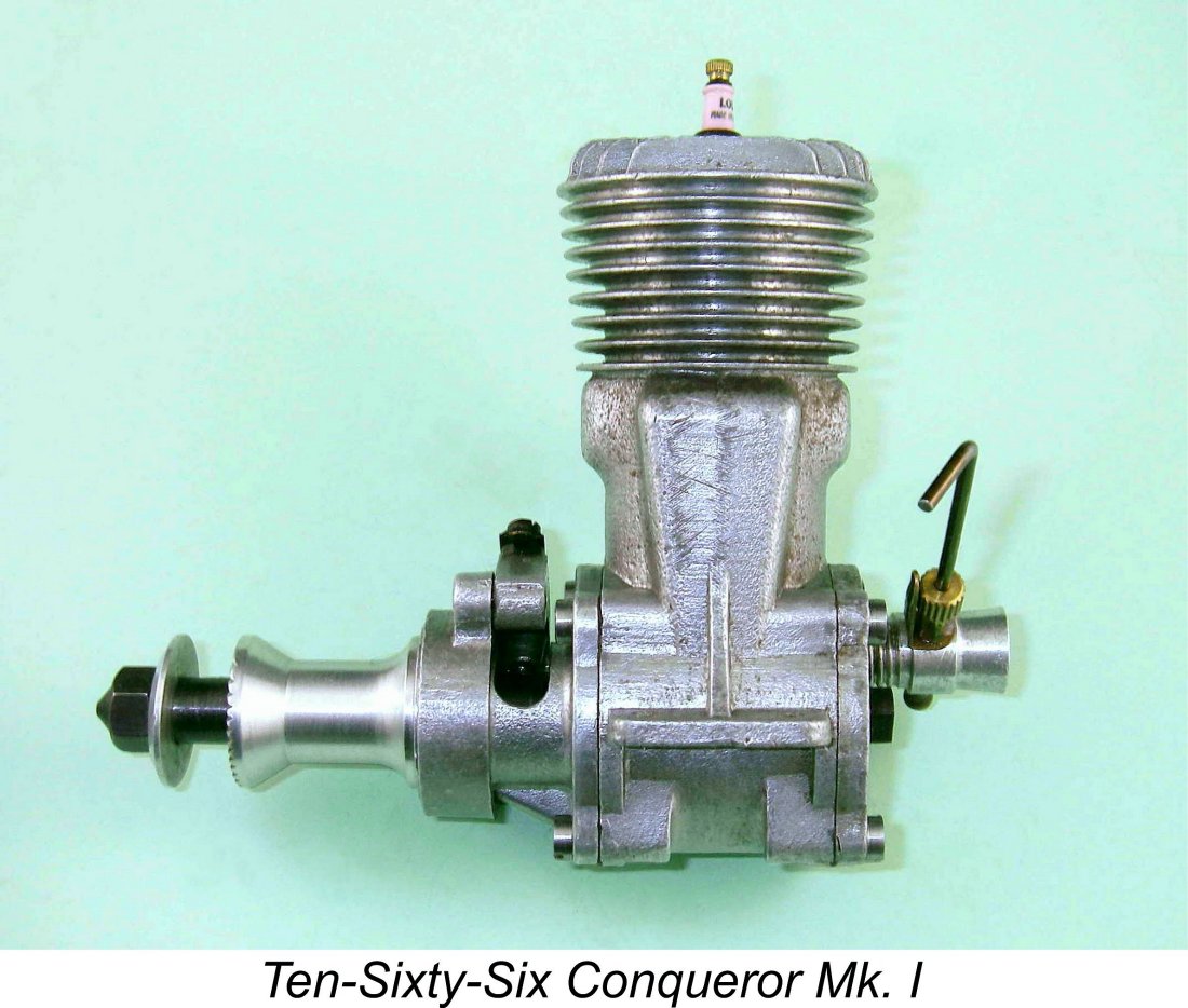
 American-made
 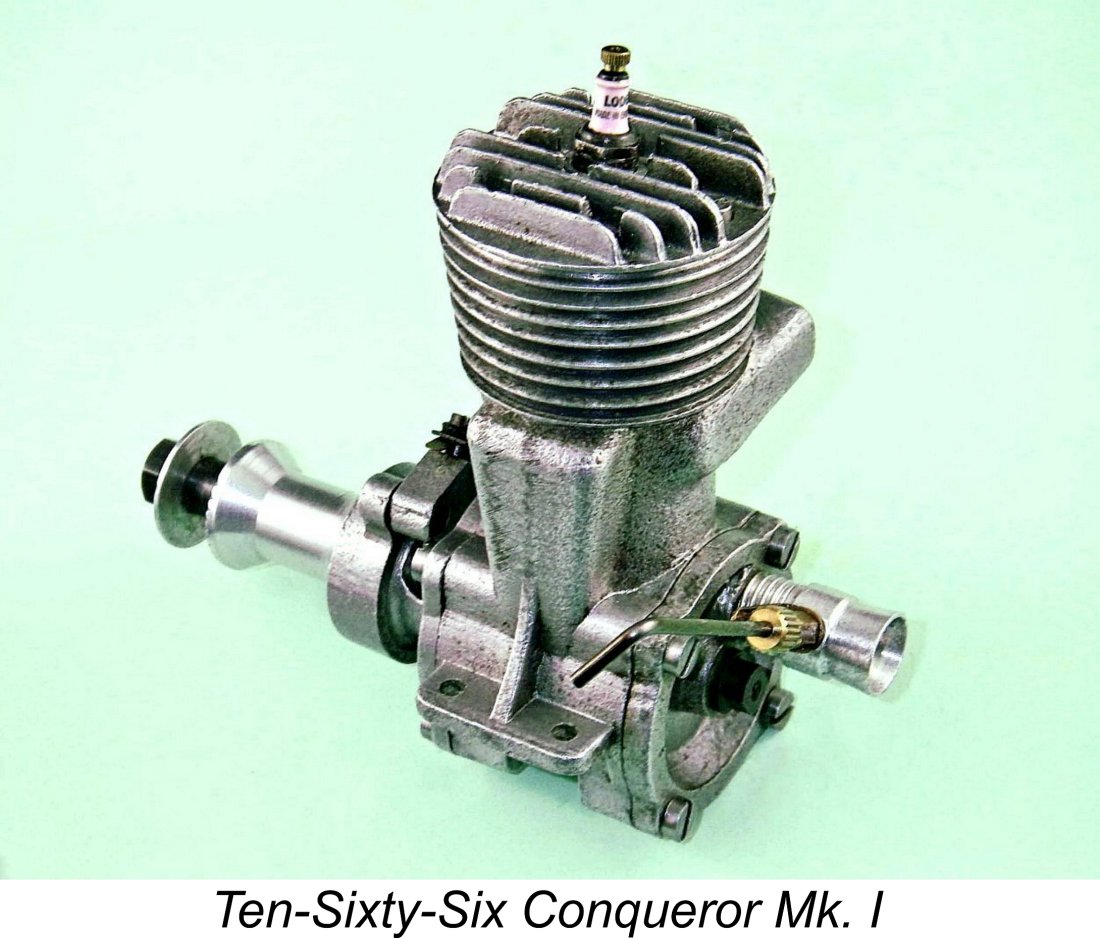 Reported weight of the Conqueror as given by Warring was 15 ounces. As stated earlier, the illustrated example weighs in at 15.73 ounces, a more or less typical figure for a 10 cc spark ignition racing engine of the period. One of Hugh Blowers' factory Mk. I models with plug, prop driver and nut weighs 15.25 ounces, indicating that individual construction approaches could significantly affect the final weight of the engine. Warring may well have been referring to the presumably lighter glow-plug model, for which his cited weight figure would doubtless be appropriate.
 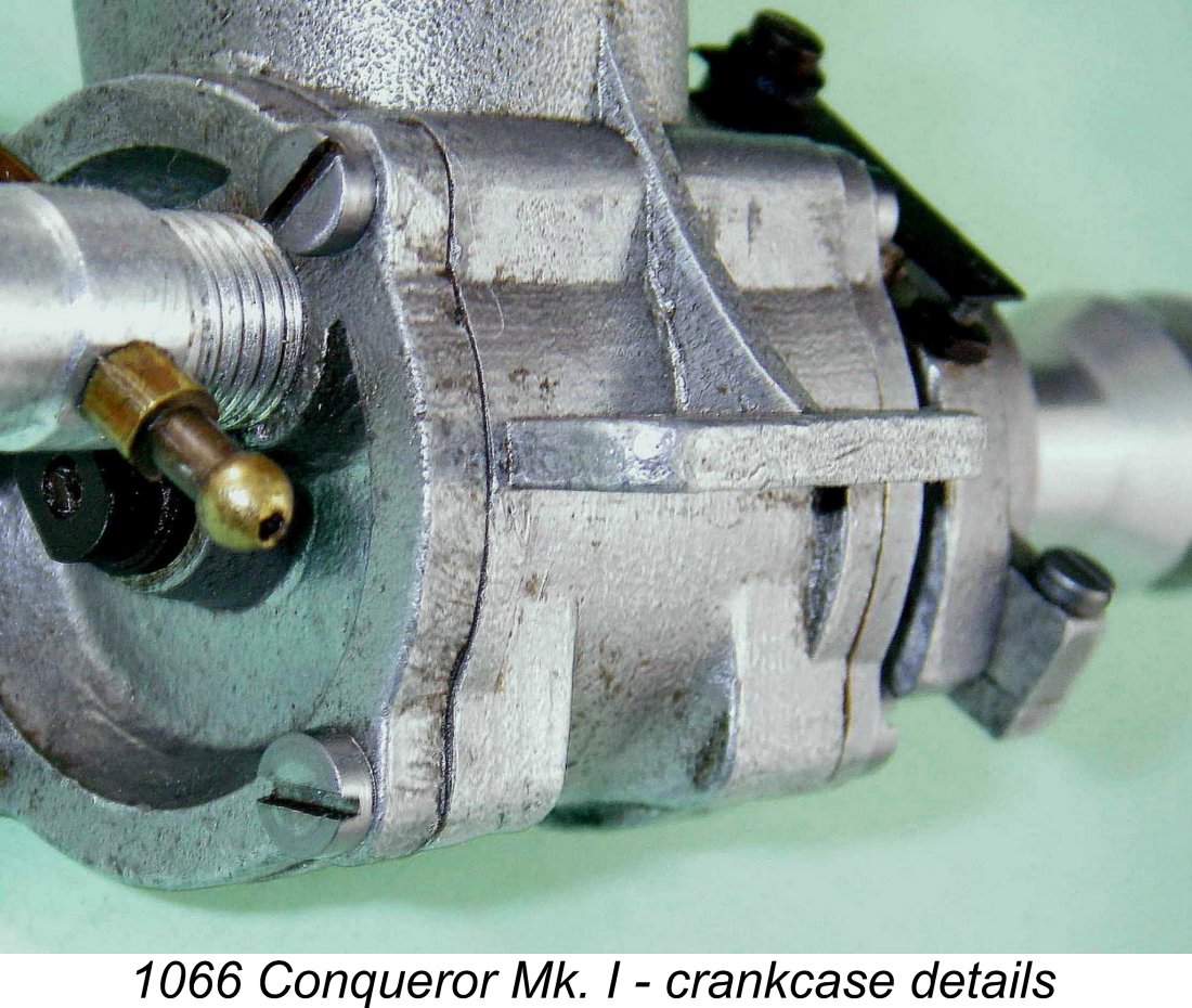 All of the cast components used in the engine are produced to a very acceptable standard by die-casting in DTD 24 casting alloy. A noteworthy feature of the main casting is the attention that has been paid to ensuring adequate strength. The mounting lugs are provided with heavy gussets on their upper surfaces, and the case thickness is greater above the lugs than it is below - the material thickness below the lugs is relieved somewhat, although bands of full-thickness material are left in place at the ends where the front and rear covers attach. A close examination of the case reveals that the engine bears no marks of identification whatsoever, nor is there any sign of a serial number.
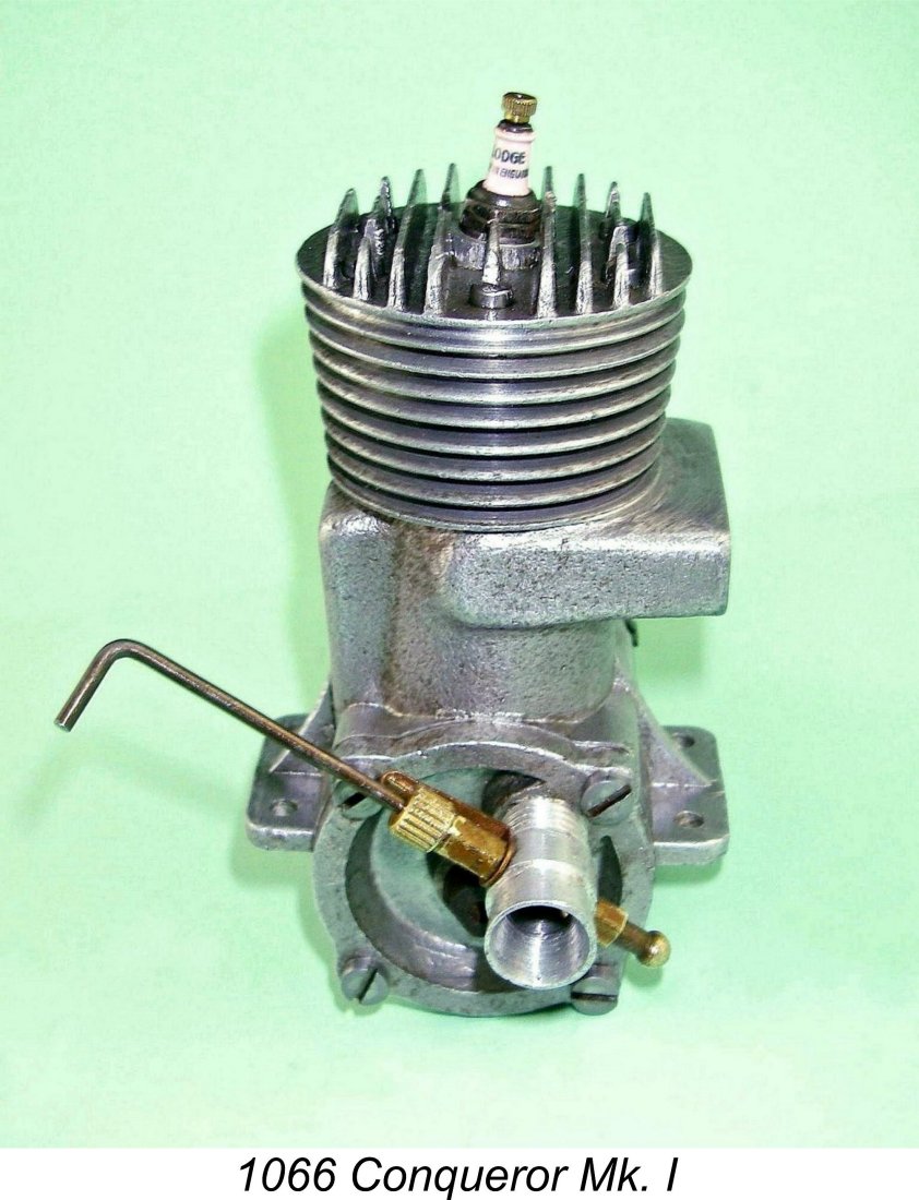 makers used whatever they had available at a given time, the consequence being that it's not at all unusual to encounter even commercial factory-built engines with differing fasteners or nuts on various examples of the same model. Much of the available supply came from war surplus sources, and manufacturers simply used whatever they could get.
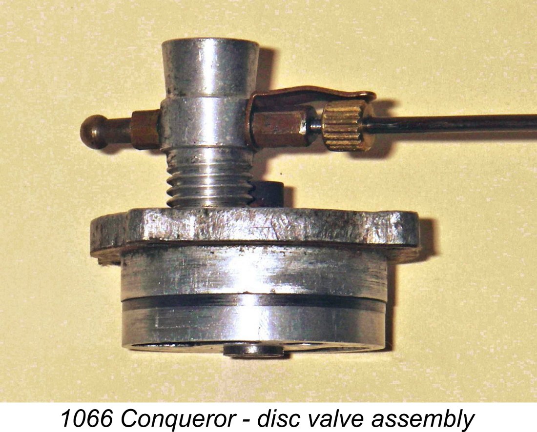 The thin steel disc has a substantial forward-facing spigot machined into its centre, and the disc bearing is incorporated into this spigot. An alloy subsidiary disc of conventional form is pressed onto the central spigot and secured in place with a pair of rivets located near the outer perimeter of the disc. The result is a disc of conventional form which has a steel wearing surface but is far lighter than it would be if made entirely of steel throughout. It also assists performance by occupying a larger volume of the crankcase than the steel disc alone would do and thus enhancing the engine's pumping efficiency. Neat!
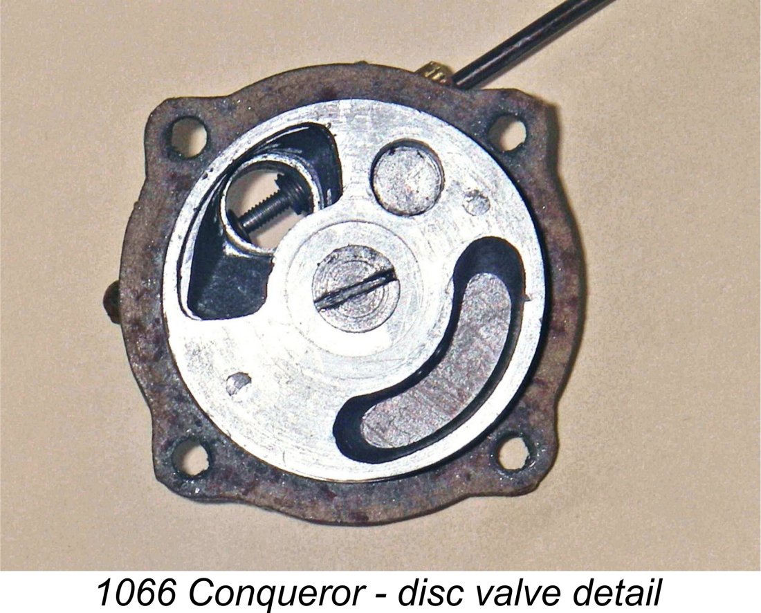 The steel portion of the disc has a ¼ in. O/D. bronze bush pressed into its centre. The backplate is centrally drilled and tapped right-handed 4BA to accept a similarly-threaded extension of the 3/16 in. dia. rotor spindle, which has a 5/16 in. dia. head to retain the disc. The threaded end of the disc mounting spindle protrudes through the backplate at the rear and is slotted at the end to allow for adjustment of the disc clearance. The assembly is completed by the addition of a shouldered locking collar which is internally threaded 4BA and threads onto the protruding end of the disc mounting spindle to serve as a lock-nut.
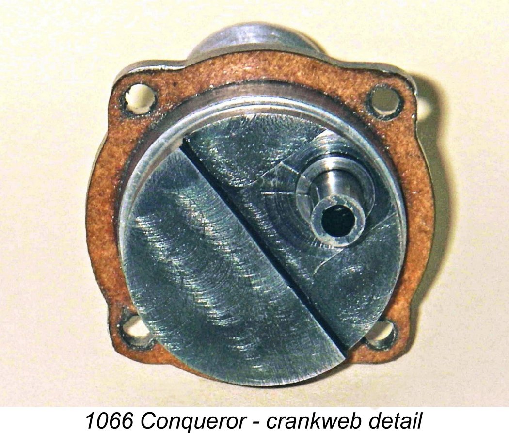 Our initial peek into the crankcase interior reveals that the casting is bored right through, with a shallow annular channel machined into the interior at the mid point to provide clearance for the conrod big end. A sturdy forged alloy rod with a bronze-bushed big end also becomes apparent. This acts upon a one-piece steel crankshaft which has a very distinctive counterbalance configuration. The milling pattern visible on the face of the crankweb shows clearly that the counterbalance was created by end-milling around the crankpin rather than by turning on the crankpin centre in the more usual manner. Only the final diameter of the crankpin appears to have been turned. Crankpin diameter is 0.250 in.
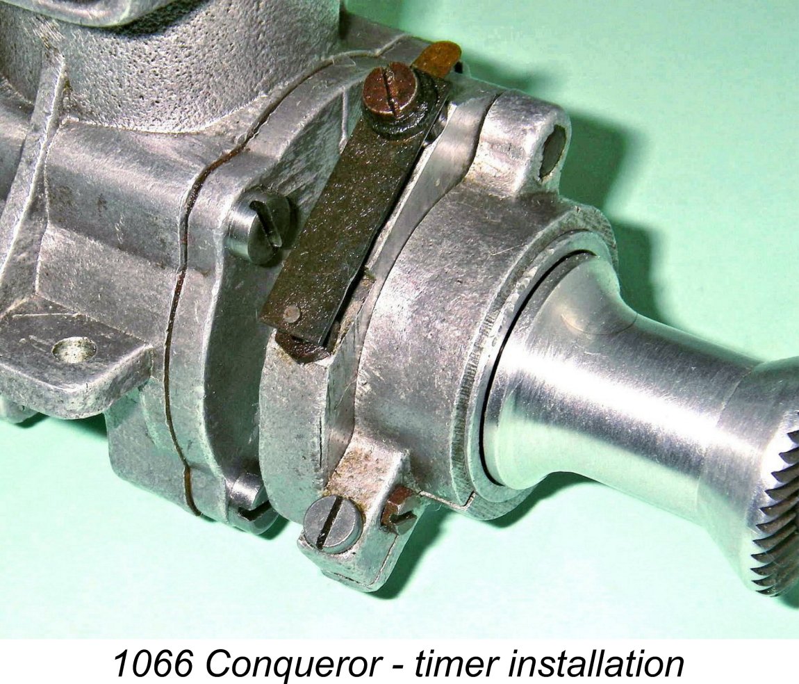 Now it's off with the front cover, which is again secured by four very sturdy 4BA steel slot head screws. Once again, a paper gasket is used to ensure a seal. The timer is clamped to the front bearing housing in the conventional manner and is now easily removed. It proves to be not without interest itself,
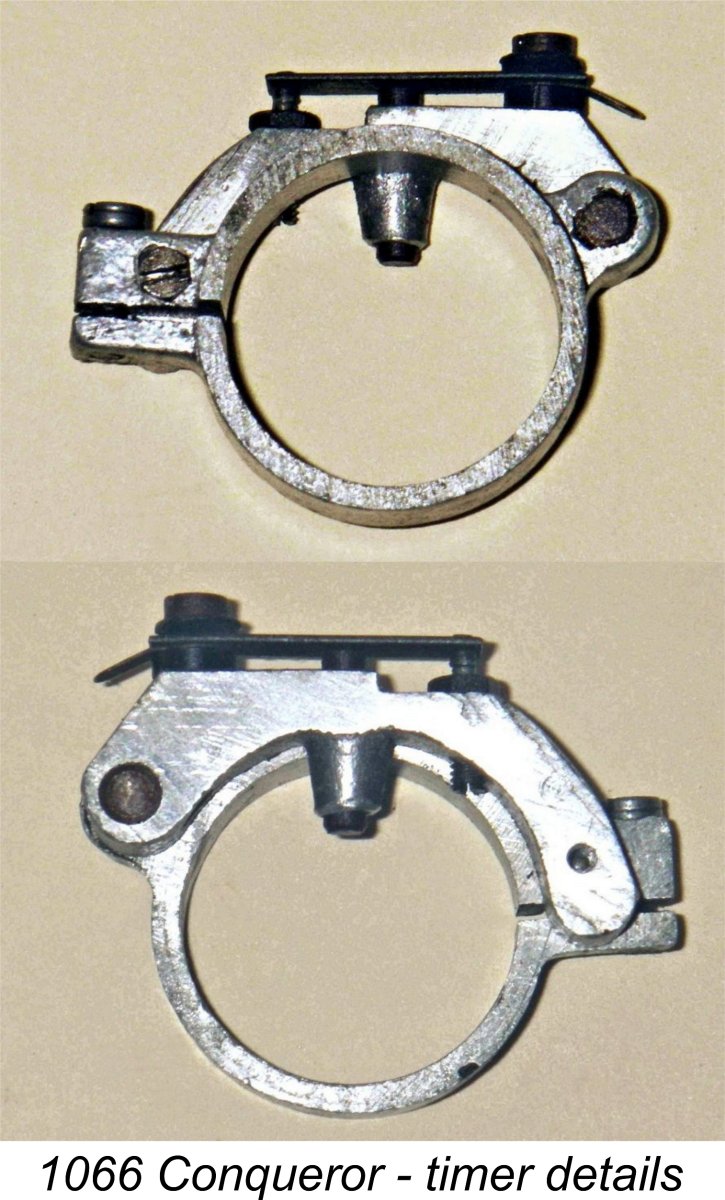
 Blowers informed me that the plans for the homebuilt version of the Conqueror show a shouldered parallel crankshaft front end requiring a split collet for mounting the flywheel or prop driver, whilst the factory-built version featured a taper on the shaft itself.
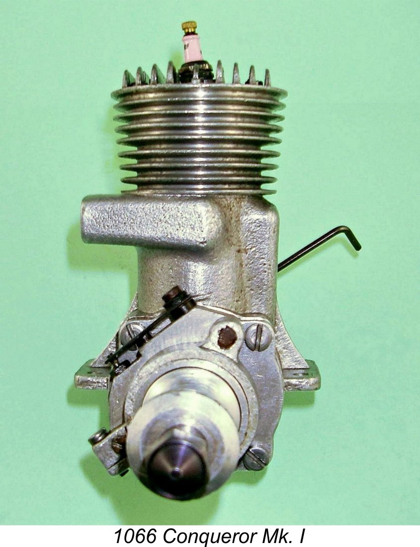 The combustion chamber is cast into the underside of the head, the plug being set at a very slight angle off the vertical. The plans specified this angle as 8 degrees, and my example closely matches this figure. The effect of this angle is to cause the interior entry point of the centrally-mounted plug to be displaced a little to the transfer side of the combustion chamber, and that was presumably the intent of this rather unusual feature. The front view of the engine at the right shows this angle clearly. The casting would seemingly have accommodated a vertical plug orientation, and it's possible that some individual builders might have adopted such an arrangement.
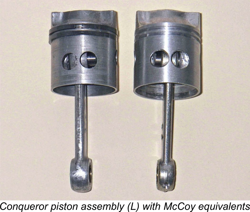 The heads and cylinder barrels were supplied with straight cast sides, so the configuration of the cooling fins was left to the individual builder. The final form would depend on such factors as personal preferences, individual skill and availability of tools. The builder of my engine clearly went to great lengths to secure as elegant a finished form as possible - the head fins were clearly turned with the head assembled onto the case.
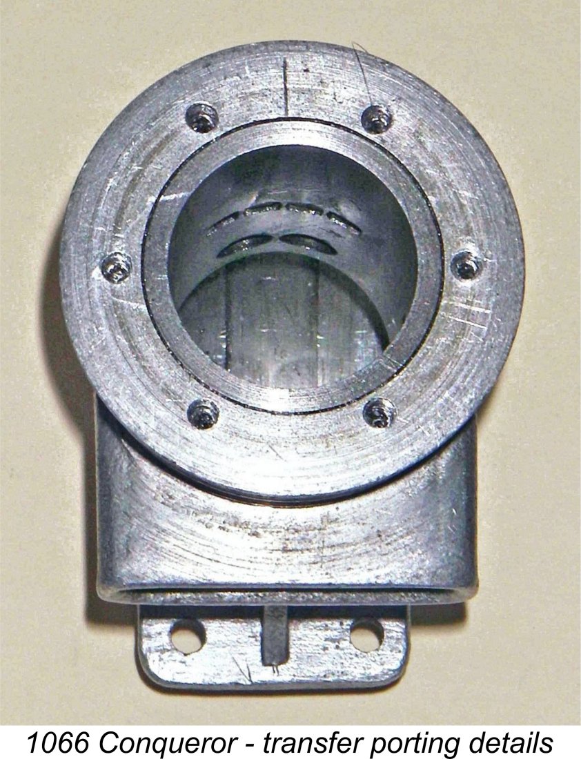
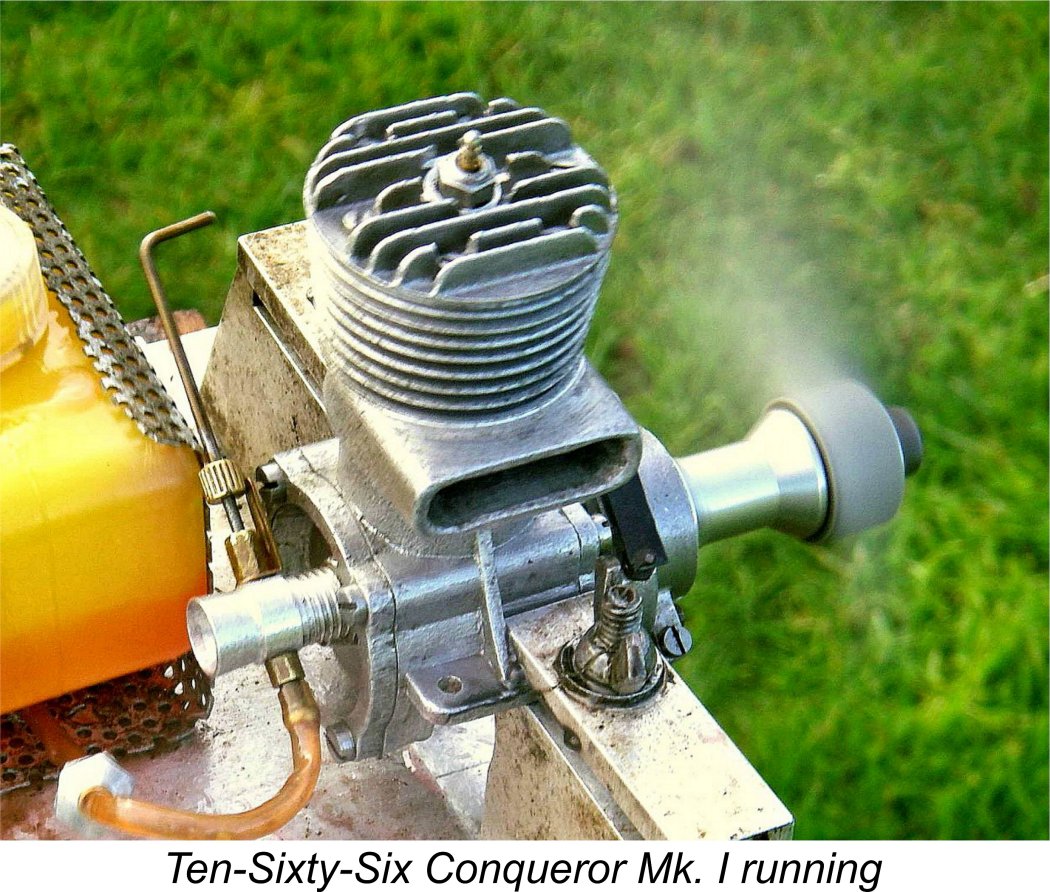 On the theory that if I didn't do it no-one else would, I decided to give my Mk. I Conqueror a brief session on the test bench so that I could report on its running qualities in my original article of 2011. However, I only tested a single prop on that occasion. For the purposes of this revised article I elected to bring it out once again and run a few additional props as a check on previous figures.
 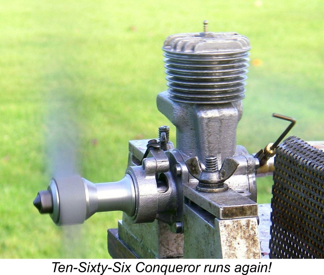 Running qualities were very good indeed, with excellent needle response. I began with my usual Taipan 11x5 grey reinforced nylon prop on which I generally test my classic 10 cc racing glows. On a few spot checks, the Conqueror turned this prop at 11,200 RPM, implying an approximate output of around 0.826 BHP at this speed. A switch to a slightly faster APC 11x6 increased the speed to 11,500 RPM - around 0.865 BHP. A final check using an APC 10x7 got the engine up to 12,000 RPM for an implied output of around 0.845 BHP. It appears that the test engine peaks at around 11,700 RPM, at which speed it is developing some 0.870 BHP.
 | |