
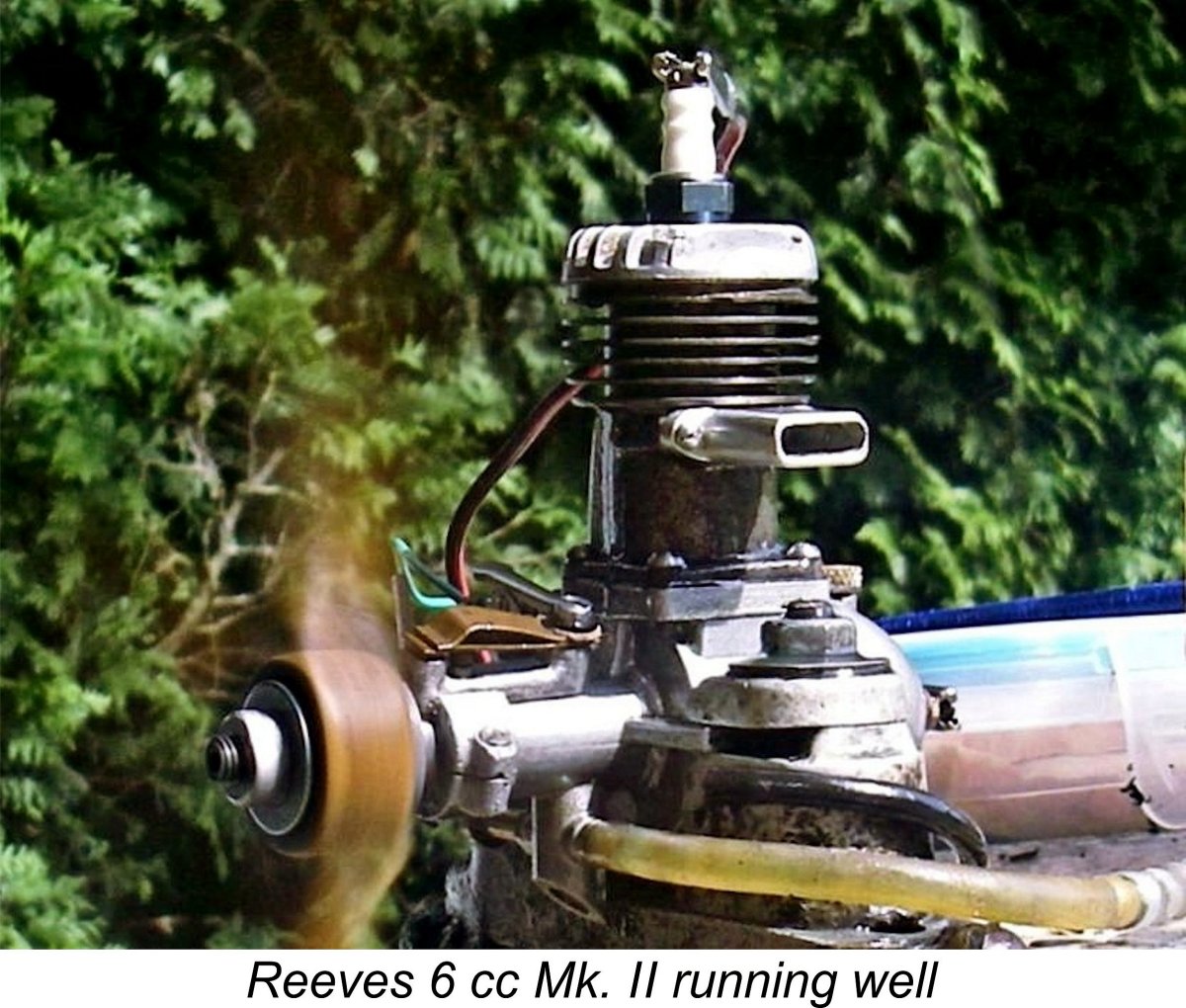
|
|
The Reeves 6 cc Spark Ignition Engine By Adrian Duncan with Maris Dislers
A very brief commentary on this engine may be found here on the late Ron Chernich's fascinating but now frozen "Model Engine News" (MEN) website. However, this article provided minimal detail, making a more comprehensive review highly desirable. In embarking upon this task, it’s both a duty and a genuine pleasure to acknowledge the invaluable assistance and encouragement provided (as always) by my good mate Maris Dislers of Australia (my own birthplace!). Maris and his colleague Don Howie undertook a test of their own incomplete example of the engine in glow-plug configuration and were good enough to share their results with me. Maris also contributed some invaluable insights into the engine’s design. One of Maris's key insights related to the somewhat retrospective design of the Reeves 6 cc model, even by the standards of 1946. To address that point, we need to look at some background, as always. Here goes ……… Background Although large-scale model engine manufacture had become very well established in the USA prior to the onset of WW2, the development of the industry in Britain had been significantly less rapid. In large part, this was due to the far smaller economically-empowered British consumer base. The relatively high cost of model engines by comparison with the average Briton’s pre-war take-home pay packet initially restricted participation in power modelling to the better-heeled members of British society, particularly those who were somehow able to obtain engines from the USA. The predominant mainstream activity during this period involved gliders and rubber-powered models.
Of course, a number of individuals having both the required model engineering skills and equipment did manage to produce their own engines on a very limited basis for their own use and that of their friends. A number of these engines still survive today as “wotizit” units whose makers’ names are now lost to us. Many of these unattributed one-off motors display outstanding workmanship meeting the best model engineering standards. Check out pp. 212-213 of Mike Clanford’s very useful if sometimes unreliable 1988 “Pictorial A-Z of Vintage and Classic Model Airplane Engines” to see a representative sampling of these products of talented unknown makers.
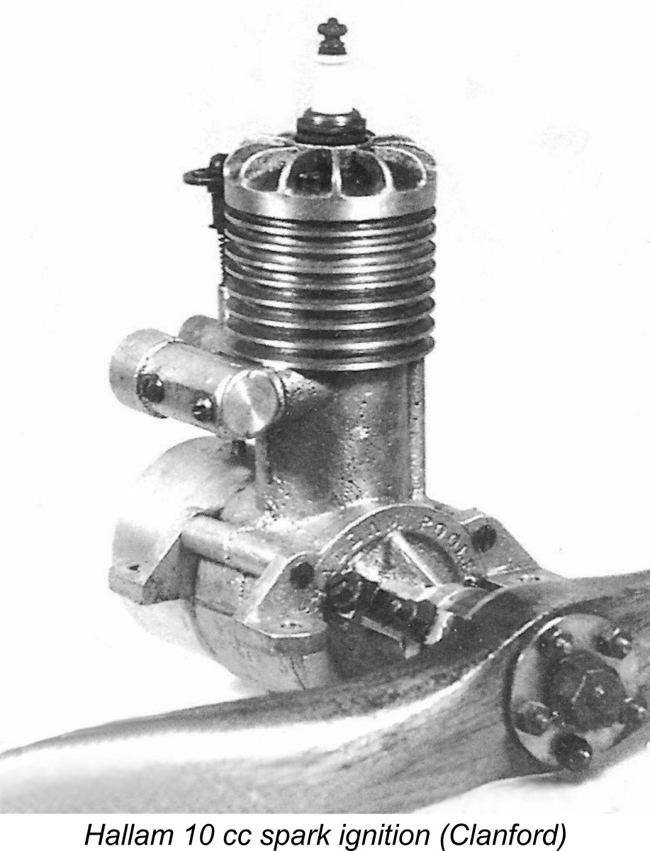
Towards the end of the nineteen-thirties, a couple of British firms did manage to become established as somewhat larger-scale producers, most notably the Hallam company of Poole in Dorset, who produced a surprising diversity of engines both before and after the war. There was also the Leicester-based firm of Rogers & Geary, who produced the Spitfire 2.5 cc, Accordingly, the manufacture of model spark-ignition engines was in the process of becoming increasingly well-established in Britain as of 1939. However, all of this progress was brought to a crashing halt by the September 1939 commencement of Britain’s 5½ year embroilment in WW2. The efforts of all of the nation’s more capable precision engineering firms, large and small, became necessarily focused upon the war effort, leaving model engine development and manufacturing in Britain pretty much at a standstill. Quite apart from the focus on war production and the accompanying wholesale diversion of materials and expertise to that activity, the fact that the flying of powered model aircraft was officially banned for most of the war-time period effectively stopped the British power modelling movement in its tracks. A number of individuals used their now-grounded aero engines in model cars, which were not banned, but there was no incentive to continue the development of such engines during the war years. Of course, all of the engines produced up to this point had been spark ignition types – indeed, British power modellers were widely referred to as petrol enthusiasts or (more colloquially) “petroleers”! The model compression ignition engine (commonly if improperly referred to as a “diesel”, which it isn’t!) had made its commercial debut with little fanfare in Switzerland during the 1930's with the advent of the ETHA units, but the onset of the war had effectively sidelined British manufacturers who might otherwise have pursued the development of diesels themselves.
Naturally, with the mid 1945 conclusion of the war, British manufacturers were once again free to take up the development of their own new model engine designs. Word of the evolving diesel technology had of course spread to Britain by this time, but British manufacturers were at least four or five years behind their Continental colleagues when it came to the development of diesels, thus being very definitely in catch-up mode. It's greatly to their credit that they did manage to catch up so quickly. However, that observation did not apply to spark ignition technology, which had been quite well developed in Britain before the hiatus resulting from the outbreak of WW2. Moreover, many pre-war British power modellers had become well versed in the operation of spark ignition engines, hence being quite happy to take up where they had left off. This being the case, it comes as no surprise to observe that the first rash of new models to appear from British manufacturers following the conclusion of WW2 were spark ignition designs, since that was what both these firms and their customers were familiar with. Moreover, the designs themselves were pretty much retrospective, essentially reflecting the state of British model engine design as it had been “frozen” by the events of 1939.
Consequently, a considerable pent-up demand for model engines in Britain became apparent very quickly. This was doubtless driven in large part by a natural post-war desire to return to normalcy by resuming peace-time hobbies as quickly as possible. In addition, the novelty appeal of model engines during those early post-war years remained just as great as it had been during the pre-war period, when such units were relative rarities on British flying fields. Moreover, the possession of an engine may have conferred a measure of "status" among the modelling community at large. Although the cost of such engines was significant in the context of the cash-starved British post-war economy, their novelty status encouraged people to save up and buy them anyway. Engines were in relatively short supply at the time, so any motor that would start and run reasonably well most of the time was pretty much assured of a buyer.
The long-established Rogers & Geary and Hallam firms both resumed model engine production after the war. Even KeilKraft got into the act with their beautiful but fragile K6 model, which may or may not have been designed at least in part by Harold Kemp. Now here’s the important point to which this discussion has been leading - all of these products were throwback designs which very clearly and unambiguously reflected the British model engine design style which had evolved prior to the onset of WW2 as British manufacturers of that period struggled to catch up to their pre-war American counterparts. Basically, these manufacturers picked up in 1946 where the British industry had left off in 1939, sticking with what they already knew while working behind the scenes to gain an understanding of the emerging design trends which would be reflected by the new models which were to begin appearing in mid to late 1946.
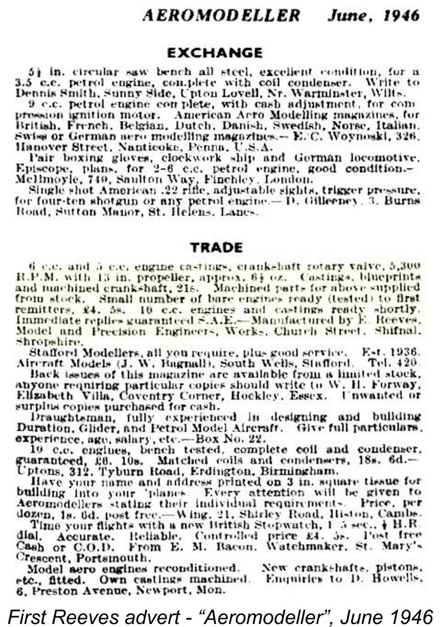
Naturally, the development of new road car models had been suspended for the duration of the war as other priorities were addressed. Consequently, that 1947 Rover car is actually the 1938 model, brought back into production for a few years after the end of the war to buy the company some time to work on an updated replacement. In the same way, the Reeves 6 cc engine and the other similarly retrospective post-war British engine designs mentioned earlier can fairly be considered as pre-war creations which emerged belatedly in 1946 as stop-gap offerings pending the development of new updated models. Of course, the model engine manufacturing field was by no means left entirely to the relatively large-volume manufacturers. The end of the war had left a significant number of technically-skilled military and civilian personnel looking for fresh outlets for their talents. Those among them who were interested in The result was the emergence in early post-war Britain of a significant number of small-scale “cottage industry” model engine manufacturers, some of them working quite literally in the proverbial garden shed (or cow-shed in the case of the makers of the Clan engines from Fife in Scotland!). Among these small-scale manufacturers was one Edward Reeves, a resident of the small market town of Shifnal in Shropshire, England. All that is presently known of this individual is that his name was indeed Edward Reeves – his first name is confirmed both by later statements from Peter Chinn and by the address on a surviving box which was used to return an example of our subject 6 cc petrol engine to the maker for service in 1947. The date is confirmed by a piece of newspaper dated July 4th, 1947 which was used to line the box and is still in it! Many thanks to my good mate Kevin Richards for supplying this fascinating piece of evidence. The first product of Edward Reeves’ fledgling model engine manufacturing business was the central subject of this article – the Reeves 6 cc spark ignition model. From this point onwards, I’ll focus upon that design. The Reeves 6 cc Model – Production History Edward Reeves entered the model engine manufacturing business in the first half of 1946 under the name E. Reeves, Model and Precision Engineers, working from an un-numbered address on Church Street in Shifnal. The company name was later changed to Reeves Model Power Units, along with a change of address to nearby Victoria Road. The latter is now part of the A464, But that is to get well ahead of our main story. As far as I’ve been able to discover, the first Reeves advertisement was a low-key placement in the “Trade” section of the Classified Advertisement feature in the June 1946 issue of “Aeromodeller” magazine. This advertisement offered castings, blueprints and pre-machined components for a spark ignition engine which was reportedly available in both 5 cc and 6 cc displacements. A limited number of completed and tested engines were also said to be available to first-comers. A 10 cc model was mentioned as being in preparation, but as far as I'm aware there’s currently no physical evidence that this design ever materialized. The initial advertisement was repeated with minor variations in several subsequent issues of “Aeromodeller”. These advertisements were all placed in the name of E. Reeves, Model and Precision Engineers, at the Church Street address. No numbered street address was ever used, presumably because (in typical contemporary British small-town fashion) Edward Reeves was sufficiently well known as a resident of Church Street to ensure correct delivery without a number. The 5 cc variant appears to have been offered only as a casting set - I'm not currently aware of any evidence to suggest that there were any factory-made examples. Presumably most buyers wanted the 6 cc model for the sake of its presumably higher output. According to my late and much-missed mate Ken Croft, both the bore and stroke of the basic 6 cc design were reduced to achieve the lesser 5 cc displacement. The castings for the 5 cc model remained on offer until at least December 1948. Presumably any surviving examples were constructed from these castings, although at present I'm not aware of any such units.
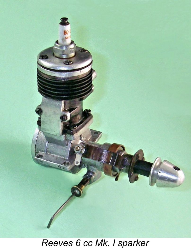
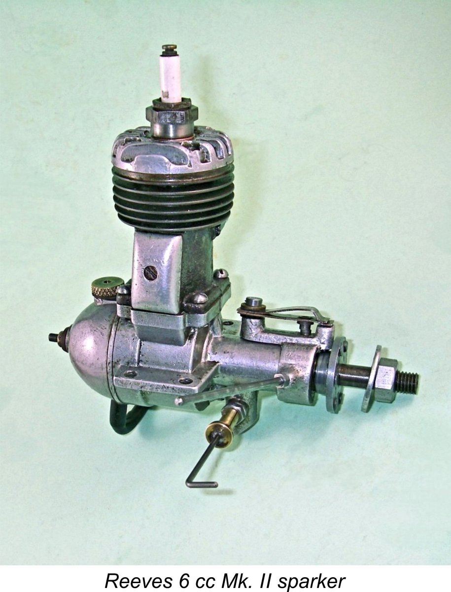
The Reeves 6 cc model which clearly became the firm’s initial bread-and-butter offering remained in production for some two years going up to mid 1948. At some presumably early point during its production life it underwent a few design changes to create a Mk. II version. I’ll discuss the two variants in the following section of this article. The Mk. II version is by far the most commonly-encountered variant today. My own illustrated example is one of those models.
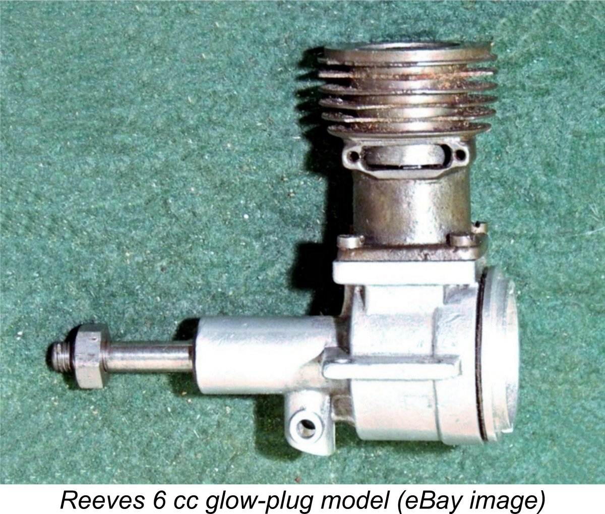
Notwithstanding the relatively small production volumes achieved, the successive variants of the Reeves 6 cc sparker evidently sold steadily enough that the small workshop in which they were made was kept quite sufficiently busy to justify both continued production and further product development. The cited price of £5 10s 0d (£5.50 - a lot of money at the time in question) was clearly no deterrent. According to Peter Chinn, the engine deservedly acquired a very positive reputation among active modellers. Of course, nothing ever stays the same. Ray Arden’s November 1947 introduction of the commercial miniature glow-plug in America heralded the beginning of the end for the spark ignition engine in that country. At the same time, the model diesel was already well and truly in the ascendant in Britain, while the glow-plug quickly made its appearance in that country too. The writing was clearly on the wall for the spark ignition motor. Edward Reeves undoubtedly recognized this, and it was in early 1948 that he took a significant step towards the future by ending production of the trusty 6 cc sparker in favour of his first diesel design, the so-called 3.4 cc model (which actually had Although production of the spark-ignition version of the Reeves 6 cc model seems to have ended at this point, castings continued to be offered until at least December 1948, when they were still appearing in Reeves' advertising. There is evidence to suggest that a few examples were constructed in glow-plug form, either by Reeves or by purchasers of his casting sets. This form of ignition arrived in Britain fairly early on in 1948 after its late 1947 introduction to the American market - KeilKraft were offering their own glow-plugs by February 1948. A few examples of the Mk. II Reeves 6 cc sparker were evidently completed in glow-plug form either by Reeves or by others using his castings. An incomplete and severely battered example of this variant appeared some years ago on eBay. Although the engine was incomplete, it was an indisputable fact that there was no provision for (or evidence of) a timer having been fitted, seemingly proving the engine’s glow-plug heritage. It had certainly seen operation as a glow-plug unit. Having summarized the engine’s production history, it’s now time to turn our attention to a detailed description of its main features. The Reeves 6 cc Model – Description
To begin with, it should be made clear that the two variants of the engine are basically very similar, differing only in detail. I'll attempt to clarify the detail differences as we proceed. In most respects, the Reeves 6 cc model is a fairly representative example of the early post-WW2 products of the British model engine manufacturing industry. Like the others, its general design arrangement is an obvious throwback to the British spark ignition designs which had begun appearing immediately prior to the onset of the war. I’ve discussed the reasons for this in the previous section of this article. As always, we may as well begin with the tale of the tape. I've chosen not to disturb my seemingly "experienced" example of the Mk. I variant, so operational dimensions taken from my Mk. II example will have to do. It's very likely that those dimensions remained unchanged between the two versions. In the However, Maris Dislers reports bore and stroke dimensions for his incomplete example of 0.770 in. (19.56 mm) and 0.750 in. (19.05 mm) for a calculated displacement of only 5.73 cc (0.349 cuin.). The two examples agree with respect to their bore dimensions, but there’s no agreement with respect to the stroke. I’ve repeatedly re-checked my Mk. II's stroke figure, and keep coming up with the same result! My figure is actually more consistent with the engine’s nominal 6 cc displacement. Just to mess things up, it must be admitted that rough measurements taken from my recently-acquired Mk. I example (without dismantling it) agree with Maris's figures. It appears that the displacements in which these engines were produced were somewhat variable!
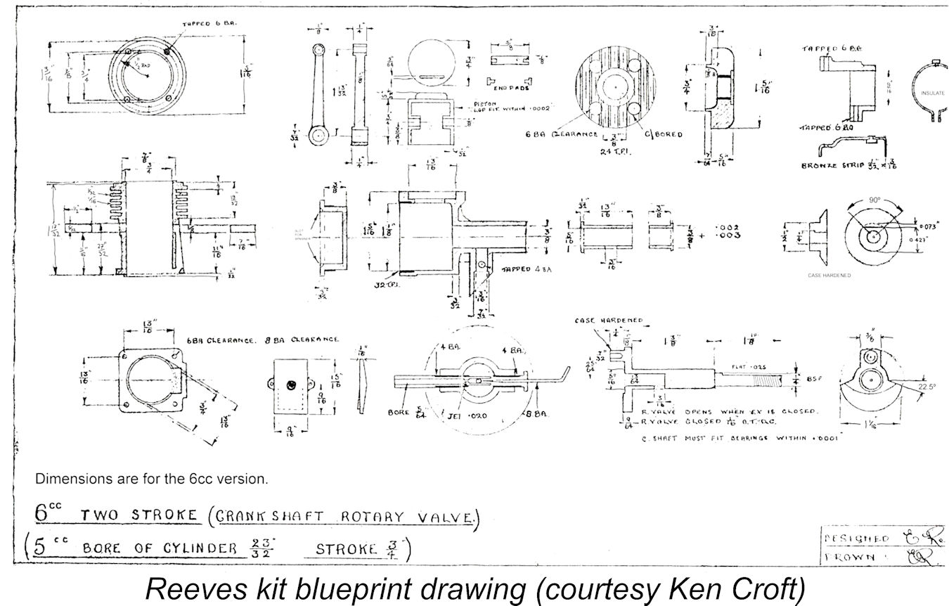
Just to make life absolutely perfect, Peter Chinn cited the bore and stroke of the engine as 25/32 in. (0.781 in. - 19.84 mm) and 3/4 in. (0.75 in. - 19.05 mm) for a calculated displacement of 5.89 cc (0.359 cuin.). I give up - take your pick! It appears from all of this that a range of different dimensions were applied to both the bore and stroke of this basically individually-produced engine. For now, I’ll stay with the figures from my own examples, which I’ve confirmed beyond doubt. Thankfully, my late and much-missed friend and colleague Ken Croft was able to supply an invaluable piece of evidence in connection with this issue. He managed to come up with a blueprint from one of the original casting kits offered by Reeves for this engine. This drawing was signed by E. Reeves, identifying him as the designer. More to the point, the intended design bore and stroke dimensions for both 5 cc and 6 cc variants were clearly indicated.
The 5 cc version was evidently based upon the same set of castings but had bore and stroke dimensions of 23/32 in. (0.719 in./18.26 mm) and 3/4 in. (0.750 in./19.05 mm) respectively for a displacement of 4.99 cc (0.304 cuin.). It's apparent from the evidence that bore and stroke figures for different examples of the same model varied considerably. It's impossible to determine at this late date whether these variations resulted from the efforts of different kit builders or whether Reeves himself produced examples having different working dimensions. Back to reality ..............checked weights for the two 6 cc variants are 222 gm (7.83 ounces) for the tankless Mk. I (which never had a tank) and 224 gm (7.90 ounces) for the Mk. II complete with back tank. Both weights include the plug, but are of course minus the necessary ignition support system. The figure for the Mk. II matches that reported by Peter Chinn exactly. Once again, both Chinn and I are at odds with Warring’s stated figure of 8.5 ounces. One really does begin to wonder if Warring ever actually had an opportunity to handle and measure an example for himself ……….. Maris Dislers reports that his bare Mk. II engine weighs only 193 gm (6.8 ounces) minus tank, fuel tubing and timer, which is entirely consistent with my figures and that reported by Chinn. Volumetric measurement of the compression ratios of both my Mk. I and Mk. II examples yields a figure of 7:1 for both units. This is a quite rational figure for a low-speed spark ignition unit. Maris reports that his Mk. II example has a measured compression ratio of only 6:1, exactly as cited by Peter Chinn. This is still within acceptable limits for an engine of this type runing on spark ignition, although it's on the low side for glow- Warring cited the manufacturer’s airscrew recommendations as being an 11x6 prop for free flight and a 9x8 for control line. We’ll have an opportunity to evaluate these recommendations in due course. So much for the rather confused numerical story. In terms of its construction, the engine displays a number of derivative features from various sources. The crankcase is a neat gravity die-casting which incorporates the main bearing housing and the updraft front intake venturi in unit. It is closed at the rear with a separate screw-in alloy backplate. The cylinder is a hefty iron casting which is attached to the crankcase using four machine screws. It incorporates the cooling fins and an open bypass passage which is closed with a separate aluminium alloy cover plate, rather reminiscent of the arrangement seen on the infamous G.H.Q. engines from America, which also featured a cast iron cylinder unit. The bypass cover is secured by a pair of machine screws on the Mk. I version of the engine, while the Mk. II unit uses a different cylinder casting which accommodates the use of only a single centrally-placed screw to retain the bypass cover. In both variants, a gasket is used to ensure a good seal.
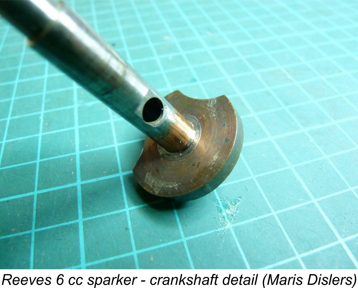
At the top, the bore is sealed by an alloy cylinder head which is secured by four machine screws. This head presents a generously-domed combustion chamber to the piston. Most of the heads seen on both Mk. I and Mk. II engines are cast components having generous longitudinal fins cast onto their upper surfaces. However, my Mk. I example has a plain unfinned head which appears to have been machined from bar stock. Perhaps Edward Reeves was short on cylinder head castings that day .......... There is ample clearance in the combustion chamber to accommodate the piston baffle at the top of the stroke. The need to provide such clearance doubtless set an upward limit on the compression ratio. The head is provided with a centrally-located threaded plug installation hole which accommodates a 3/8-24 UNF plug, the latter being typical of early post-WW2 practice. It appears that British-made Lodge plugs were fitted as supplied, although my Mk. I unit has an equally British K.L.G. plug fitted. A gasket is used between the head and the cylinder to ensure a good seal. The cast iron piston has a high baffle on the bypass side of the crown. A cast iron piston running in a cast iron bore is normally a poor combination from a wear standpoint, as Allen-Mercury were to learn years later with their early A-M diesel models. It seems to work all right as long as the initial fit is very close, the engine is broken in very carefully to allow work-hardening of the sliding surfaces and the unit is kept scrupulously clean. However, the smallest hint of dust or dirt can result in very rapid wear. All that can be said in the present instance is that the piston fits in both of my examples and in Maris’s Mk. II engine are beyond reproach despite the running which these engines have clearly done in the past. Port timing is a bit unusual for an engine of this type. The exhaust port opens at 105 degrees after top dead centre for a total exhaust period of 150 degrees – an unusually long period for a low-speed spark ignition unit. The transfer opens only some 15 degrees later for a very generous transfer period of around 120 degrees and a remarkably short 15 degree blow-down period. These figures would be more or less appropriate for an engine having a far higher operating speed than this one. The early opening of the transfer port gives rise to another problem. At bottom dead centre a significant portion of the transfer port is clearly visible through the exhaust port. In fact, the port is only obscured by the baffle for approximately the first and last 40 degrees of the 150 degree exhaust period. This cannot be viewed as a positive design feature since it would undoubtedly allow some of the fresh incoming mixture to s The piston drives the crankshaft through a cast aluminium alloy con-rod. Bearing fits at both ends of the rod are excellent. The crankshaft is a one-piece component of case-hardened steel. It features a drilled induction port which has been enhanced by milling a flat across the journal surface at the port location, thus increasing both its opening and closing rates. Like the cylinder porting, this feature is again more of a typical high-speed design feature than we would expect in an engine of this type. The induction port opens relatively (and seemingly unnecessarily) late at around 70 degrees after bottom dead centre. An interesting observation made by Maris is the fact that the front and rear sections of the main journal as well as the front of the crankweb are copper-plated. This was presumably done to shield those surfaces from the case hardening process, which can otherwise impart some unwanted brittleness to the treated steel.
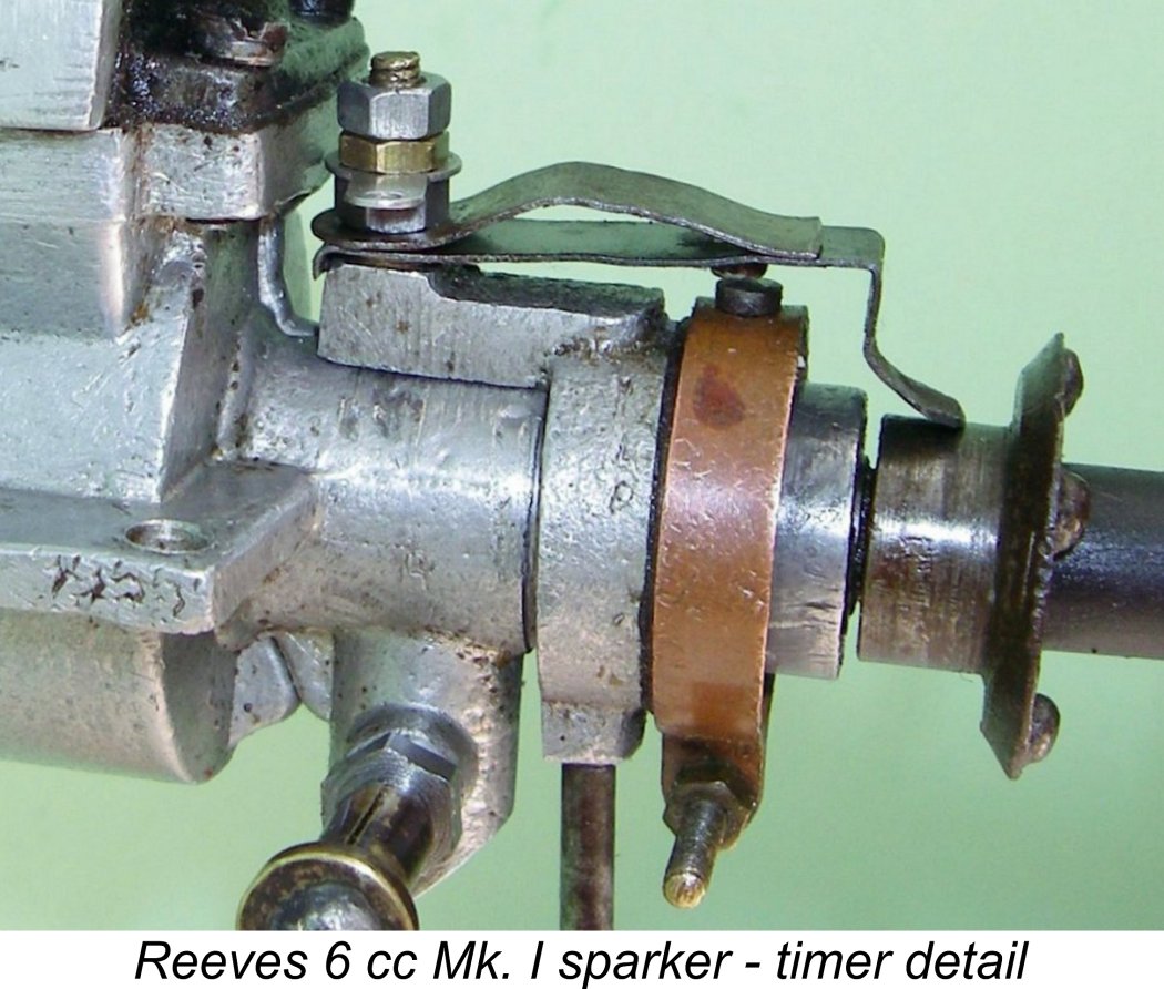
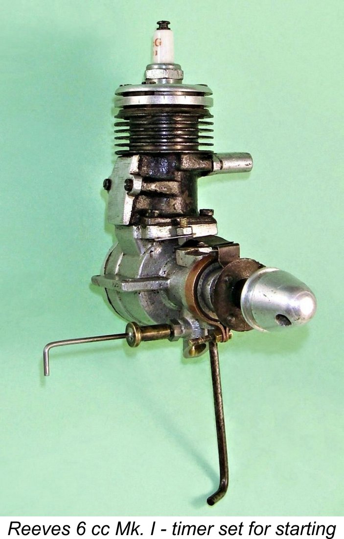
The timer on both Mk. I and Mk. II variants is of the axially-oriented open-frame type which was by then becoming obsolete in American practise – another definite throw-back feature. The timer used on the Mk. I version was of the very simple type which used a bent portion of the flexible spring moving point carrier as a cam follower. My Mk. I example features a second back-up leaf spring to increase the spring tension in the system. The Mk. II variant features a far more sophisticated arrangement which uses a non-metallic plunger-type cam follower. The separate back-up leaf spring is retained to improve timer response at higher speeds.
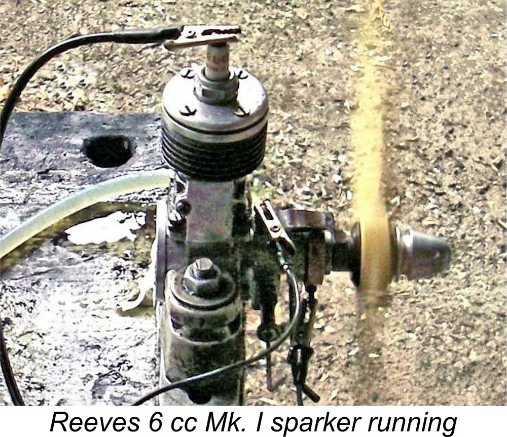
The positioning of the cam on the prop driver dictates that the points be located somewhere near the top of the main bearing in order to establish the required ignition timing. Indeed, the presence of the needle valve and intake confine it to this general location. This being the case, one would expect the timer's adjustment arm to be oriented in a more or less lateral alignment for convenient access during operation. And indeed, the timer arms of both my Mk. II model and the previously illustrated finned-head Mk. I unit extracted from Mike Clanford's previously-cited "A-Z" book are oriented more or less horizontally to the right. However, the arm on my Mk. My reading of this rather unusual orientation is that the timer on this engine was expressly designed for convenient operation with the engine mounted inverted in the model. This was a very popular mounting orientation during the mid to late 1940's. A timer arm oriented in this way on an inverted engine would be located at the top of the model, hence being very readily accessible for adjustment. It would also work well in a sidewinder mounting situation. The arm does double duty by serving as a set screw to lock the timer in the required running position. When describing a spark ignition engine, an additional parameter which needs to be quantified is the dwell period provided by the engine’s timer. This is the angle of crankshaft rotation during which the points are closed and hence in direct electrical contact with each other, thus supplying current to the primary ignition circuit. This parameter is more fully discussed in my separate article on spark ignition operation. Since sufficient real time must be provided during each revolution to ensure full saturation of the primary coil winding before the points open to trigger the spark, the dwell requirement varies from engine to engine, the main factor being operating speed. A slow-speed unit like a Brown Junior, Atom .099, Bunch, Elf or even an early Ohlsson can operate successfully with a relatively short dwell period of 50 – 60 degrees or even less. Such a relatively short dwell period conserves the life of the flight batteries, since it minimizes the proportion of running time during which the points are closed and current is flowing to the coil from the batteries. It also minimizes any tendency for the coil to overheat during long runs. In the case of the Reeves, direct measurement confirms that the dwell period provided by the timers is of the order of 50 degrees for both models. Such a relatively short dwell period suggests that the engines were not expected to operate at high speeds. However, it also means that flight battery life should be relatively extended - primary current will only be flowing for some 14% of the engine's running time, regardless of the operating speed. Turning now to the needle valve assembly, a split thimble is used to provide needle tension. The spraybar is provided with an external 4BA installation thread along its entire length. A very important point to note here for conservation purposes is that the female 4BA spraybar installation thread is carried right through both sides of the spraybar installation spigot on the intake venturi. The spraybar threads right through both halves of the resulting threaded hole, being secured in the correct jet orientation by a lock-nut on the needle side. Its central section is “waisted” along the length corresponding to the intake venturi when installed, thus increasing the effective venturi throat area. Unfortunately, many of these engines seem to have had their spraybar installation holes drilled through to allow the installation of a different needle valve assembly. Any engines which have been subject to this treatment cannot be considered to be in original condition. If you have an un-drilled example, please keep it that way! The Mk. I variant of the engine was sold without a fuel tank. However, the Mk. II model is provided with a neat fuel tank of cast light alloy which is attached to the backplate through the use of a brass stud and nut. The brass fuel filler cap is of the screw-in type. Now that we’ve taken a look at the engine from a structural standpoint, it’s time to find out how it runs! On to the test bench ………….. The Reeves 6 cc Model on Test When we first collaborated on the writing of this article, neither Maris Dislers nor I were aware of a contemporary test of the engine which was hidden away in the pages of "Model Aircraft". We only became aware of this test thanks to Derek Butler's kindness in posting several issues of "Model Aircraft" for 1948 on the Vintage Glow thread in the RC Groups Forum. Much appreciated, Derek!
Chinn began by characterizing the Reeves as being "rather more of the old school of petrol motors - the engines which were developed for free-flight work at prop speeds of around 5,000 rpm". In making this statement, Chinn was providing strong support for our earlier discussion relating to the retrospective character of early post-WW2 British model engine design. Chinn found the engine to be easy to start using both forms of ignition. However, there was evidence that the compression ratio was on the low side for operation on glow-plug ignition - on low-nitro fuel, the engine developed a misfire when the battery was disconnected from the plug (there's an uncaught typo in Chinn's text here). Chinn felt that an easily-applied compression ratio increase from the 6:1 figure measured for his example would be well warranted for glowplug operation. In terms of performance, Chinn found a peak power output on spark ignition of 0.155 BHP @ 5,100 rpm. Switching to glow-plug ignition and using a fuel containing an undiscosed proportion of nitromethane, output was increased to 0.166 BHP @ 6,700 rpm. The Reeves was clearly a useful performer in the field - Chinn reported that he was then using the engine on spark ignition to power a 5 ft. 8 in. wingspan cabin model weighing 3 lb. 3 oz. (1.45 kg.). A 12 in. dia. prop was used, turning at 5,000 rpm on the ground. Interestingly, Chinn made an oblique reference to this test in his “1948/51 Engine Review” (“Model Aircraft”, June 1951). In that listing, Chinn credited the Reeves with an output of 0.17 BHP at 6,500 RPM. It was initially thought that these figures were manufacturer's claims, but we now know that they were loosely based upon Chinn's own testing using glow-plug ignition. Regardless, they appear at first sight to be perfectly reasonable figures. The primary goal of our present-day testing was to confirm their credibility. I’ll begin with the testing conducted in Australia by Maris Dislers and his Aussie colleages Don Howie, Bill Britcher and Nigel Wooton. Their test engine had lost its tank, exhaust stack, original needle valve assembly, timer and prop driver in the far distant past, but otherwise gave no evidence of having seen extensive use. Internally, the engine was in fine condition, with excellent fits all round. In particular, the piston was a very good fit in the cylinder, while the cast aluminium alloy con-rod showed little sign of use. Given the absence of a timer, our intrepid heroes were naturally forced to prepare the engine for a test on glow-plug ignition. As stated earlier, this is not inappropriate given the fact that a few examples of the Reeves are known to have been completed as glow-plug units either by Reeves or by others. Indeed, the possibility exists that the test engine was one of these glow-plug models, which would explain the absence of a timer. Maris's close inspection of the engine revealed that there appeared to be a problem with the engine's configuration as constructed. He found that the conrod was around 1 mm too short. This caused the top of the piston crown to descend below the bottom of the exhaust at Bottom Dead Centre, at which point the top of the transfer port was exposed above the baffle, allowing direct short-circuiting of incoming mixture across the piston crown and out through the exhaust. I checked my own Mk. I and Mk. II examples, finding that they both exhibited the same behaviour, pretty much confirming that this was a chronic design issue. If the piston was moved up to align the crown with the bottom of the exhaust port, the transfer was nicely baffled off. A longer rod would solve this problem while also increasing the compression ratio, something from which this engine would clearly benefit.
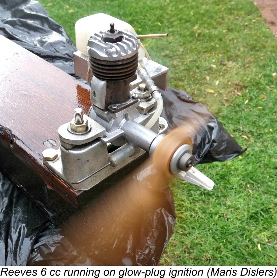
Based upon Ron Warring’s previously-cited prop recommendation, the testers began with an 11x6 wood propeller. They used a mild glow fuel having a 5% nitromethane content. Starting was found to be very straightforward following a choked turn to fill the fuel line and a small exhaust port prime directly into the cylinder. The engine was found to turn the 11x6 wood prop at 6,500 rpm, more or less exactly the speed at which Chinn claimed that the engine peaked. This lent some credibility to the prop recommendation cited by Warring. Tried with lighter loads, the engine quickly began to exhibit clear symptoms of retarded ignition timing. This situation doubtless arose from the combination of the measured 6:1 compression ratio (a rather marginal ratio for glow-plug ignition) and the operators’ inability to advance the ignition timing when running in glow-plug mode. As I’ve stated elsewhere, the leaned-out ignition timing that results from the use of a given plug in a given engine running on a given fuel is pretty much fixed, hence being optimized over a relatively narrow speed range. With a 6:1 compression ratio and a low-nitro fuel, that range may be expected to be pretty low. Peter Chinn had evidently encountered the same problem during his 1948 test. Confirmation of this retarded ignition condition was readily obtained. The testers found that on the lighter loads (notably the APC 10x4), some 300-400 extra rpm were available if the plug lead was left on while running, thereby maintaining a higher plug element temperature and hence advancing the ignition timing somewhat. Overall, the engine was clearly reluctant to work at speeds much above 6,500 rpm, at least on glow-plug ignition. A switch was accordingly made to a K.L.G. glow-plug. The fact that a considerable improvement had resulted was amply underscored by the discovery that the engine no longer slowed down when the plug lead was removed. The Reeves’ true grit soon became evident as prop sizes were increased from the 11x6 starting point. On the larger calibrated props, the engine demonstrated an ability to develop notably high torque. It may well be that the cooler-running methanol-based fuel used in glow-plug mode might facilitate the engine’s ability to swing the larger props effectively. In the end, a power curve was developed which implied a peak output of around 0.192 BHP @ 6,300 rpm under the test conditions. This actually exceeded Chinn's reported output on glow-plug ignition, albeit at somewhat lower rpm. It seems likely that the engine's peaking speed might well be increased either through the use of a hotter plug or by raising the compression ratio a little. This in turn should theoretically result in a higher peak output. Even so, Chinn's figures seem quite credible based on this test. Overall, this was a solid enough performance by 1946 standards, albeit delightfully out of step with modern technology. Wouldn’t have it any other way!! The results reported by Maris appear in tabular and graphic form below.
Having a very fine and complete example of this engine on hand myself, there was nothing to stop me from repeating the test conducted by my Aussie colleagues using spark ignition. Having then recently completed the construction of a couple of very servicable spark ignition support systems for bench-testing, I elected to skip the glow-plug stage and go straight to spark ignition. Using this system would allow me to optimize the ignition timing at all speeds tried. As far as fuel went, I used what has become my standard old-time sparkie brew of 3 parts of Coleman camp fuel (naphtha/white gas) to one part of SAE 60 mineral oil (AeroShell 120). This would obviously not be as strong-running a fuel as a methanol-based blend with a little nitro, but it's probably closer to what would have been used by the average owner back in the day. I fitted the engine with a brand new Rimfire spark plug which I had then just purchased from well-known spark ignition equipment supplier Larry Davidson, who is sadly no longer in business.
To get around this issue, I ended up using a separate tank for the test to allow the delivery of fuel by suction rather than gravity. However, that wasn't the end of the challenges - because of the updraft intake, I found that one couldn't dependably get fuel into the engine by finger-choking in the usual way. Any fuel drawn in simply dripped straight out onto the ground. It turned out to be absolutely necessary to administer an exhaust prime. This in turn created its own issues, because it transpired that in common with many spark ignition units, the Reeves really didn't like a lot of fuel in the cylinder for starting. A "dry" prime with the exhaust closed proved to be the most effective approach. Even so, it was very difficult to get the prime small enough to keep the engine happy. As a result of this, the Reeves proved to be a somewhat more challenging starter than most of the other sparkies that I've tried. I just had to keep flicking with no reaction for a while, until the amount of fuel in the cylinder was just right. At that point, the engine would suddenly begin firing and then burst into life a few flicks later. This is actually one engine that would probably be most easily tested in the inverted position. Still, the Reeves invariably did start after the seemingly obligatory flicking session. It even started immediately on those occasions on which I managed to get the prime just right! Once running, the engine was very smooth indeed in operation. The needle setting was a bit on the sensitive side, although the best setting was easily found regardless. Response to the timer control was very well marked, making it extremely easy to establish the optimal timing. Once set, the engine ran smoothly and steadily for as long as required to get a good speed reading for each prop. The exhaust residues remained completely clear thoughout. The following data were obtained on test:
As can be seen, the engine developed around 0.125 BHP @ 6,800 rpm. This is somewhat down on the figure reported by Peter Chinn for the engine running in spark ignition mode, although the peaking speed is higher. It's also well down on the figures obtained by Maris and his mates, albeit once again at a higher speed. However, it must be recalled that they were running on glow-plug ignition using a standard glow fuel with 5% added nitromethane, while I was using a straight white gas blend, albeit with fully adjustable ignition timing. I suspect that my engine would probably perform at a far closer level if operated on spark ignition using a similar fuel to that employed by the Aussies.
That said, most users back in the day would undoubtedly have run this engine on a fuel similar to that which I used for this test. This being the case, I feel that my results are probably quite representative of the engine's performance as it would have been experienced by its contemporary owners. Not a powerhouse by any means, but a sturdy performer which could swing a sizeable prop and would continue to do so for as long as required. The manufacturer's recommendation of an 11x6 prop for free flight seems entirely appropriate. The Reeves came through its test with flying colours, showing no signs whatsoever of any mechanical distress at any time. All fits remained superb, with outstanding compression but no trace of binding. It's clear to me that the Reeves 6 cc sparker would have delivered a very long useful life to its owners. I can see why Peter Chinn's view of the engine was so positive. You could never break it - you'd have to kill it with a sledgehammer (but please don't!)! It's worth noting that Chinn's earlier testing on glow-plug ignition showed a comparable output to that measured by Maris and Co., but at a higher speed. Chinn commented that the engine displayed a broader power spread around the peak when running on glow-plug ignition, significantly widening the engine's useful speed range.
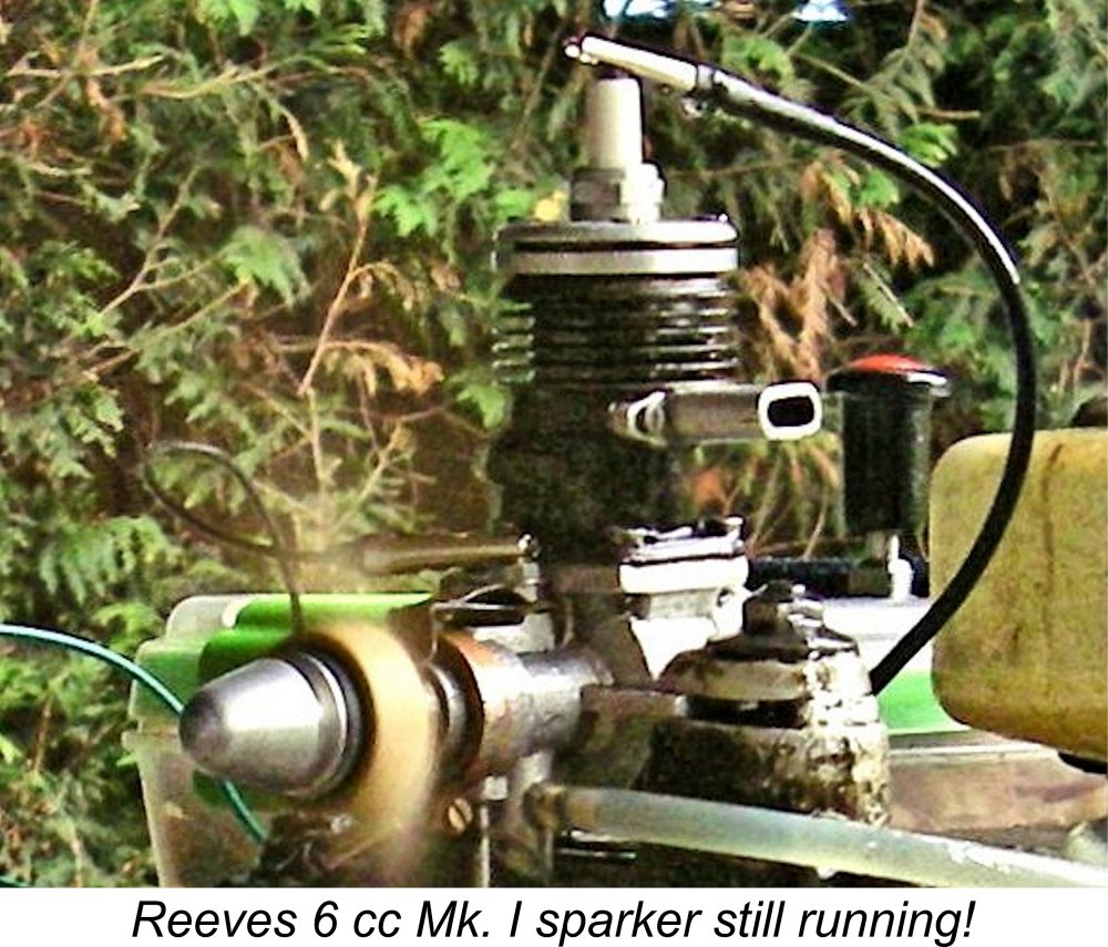
I subsequently tried my more recently acquired Mk. I model. Although complete and original, this example is relatively well used, hence having a slightly "soft" compression seal. However, there was plenty of compression for starting, while all bearings remained free from excessive play. Upon introducing the engine to the test stand, an unusual difficulty immediately presented itself. As mentioned earlier, the location of the timing control arm directly opposite the points was clearly designed with inverted mounting (then very popular) in mind. In such a mounting orientation, access to both needle valve and timer controls would be completely unencumbered. By contrast, with the engine mounted upright and the timer set at the starting position, the timer arm The very confined space between the prop disc and the front of the test stand made it quite impossible to slacken off the arm and adjust the timing with the engine running while mounted upright in the stand. Indeed, access to the needle valve was also compromised - I had to Despite these difficulties, I actually found the engine to be quite easy to start. The same approach that had worked for the Mk. II example tested earlier proved completely effective in this case also - a small prime always produced a start in fairly short order. However, the engine invariably started with the timing somewhat retarded, hence requiring a timing advance which it was impossible to apply without risking injury. I saw 4,600 rpm on a Top Flite 11x4 wood prop, but am absolutely certain that the engine would do quite a bit better than this if properly set once running. Looking at the matter objectively, it seemed very doubtful that the Mk. I unit would match the performance of its Mk. II sibling even if the settings could be optimised. Accordingly, I abandoned any attempt to obtain prop/rpm figures for this engine. However, all was not lost - at least I proved that it would start and run just fine! Conclusion The Reeves engines have a reputation for having been built to very high standards of precision, a reputation which the 6 cc sparker upholds very well. Like other early Reeves products, notably the 3.4 cc diesel which has been reviewed elsewhere, the Reeves 6 cc model was no ball of fire in the performance department, but it was nonetheless a very soundly-constructed unit which would probably have outlasted a whole string of owners! It remains a very pleasant engine to use or simply to run for fun. If you ever get the chance to acquire one, I'd recommend giving it serious consideration! _________________________ Article © Adrian C. Duncan, Coquitlam, British Columbia, Canada First published October 2019 Peter Chinn's 1948 test added August 2020 Further details of Mk. I variant added November 2022 Maris Dislers' test results refined April 2023 Original blueprint drawing added May 2023
|
||
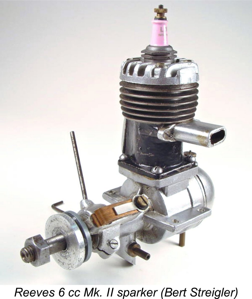 Here we take a close-up look at a typical product of the early post-WW2 British model engine manufacturing industry – the Reeves 6 cc spark ignition model. Although made in relatively small numbers in an artisan workshop, this engine acquired a very solid reputation during the two years or so in which it remained in production. Time to find out why!
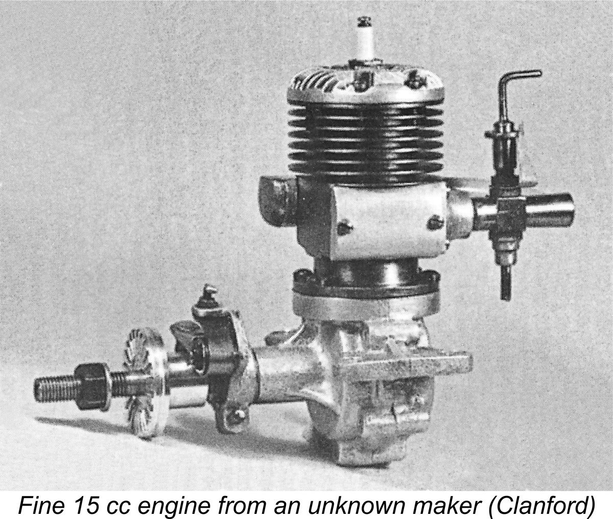 Over time, the rapid pace of development resulted in the increasing availability of good second-hand engines as their original owners moved on to the latest wunderwerk. However, market conditions in the pre-war years never really reached the point at which the large-scale series production of model engines in Britain became widely perceived as an economically viable proposition.
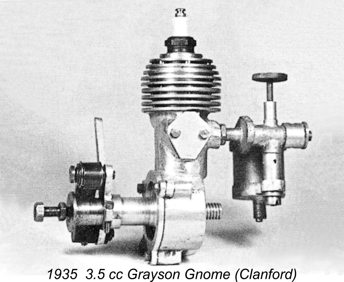
 Hornet 3.5 cc, Wasp 6 cc and (post-war) Stentor 6 cc engines for Model Aircraft Stores Ltd. of Bournemouth, later to become famous for their Veron range of model kits.
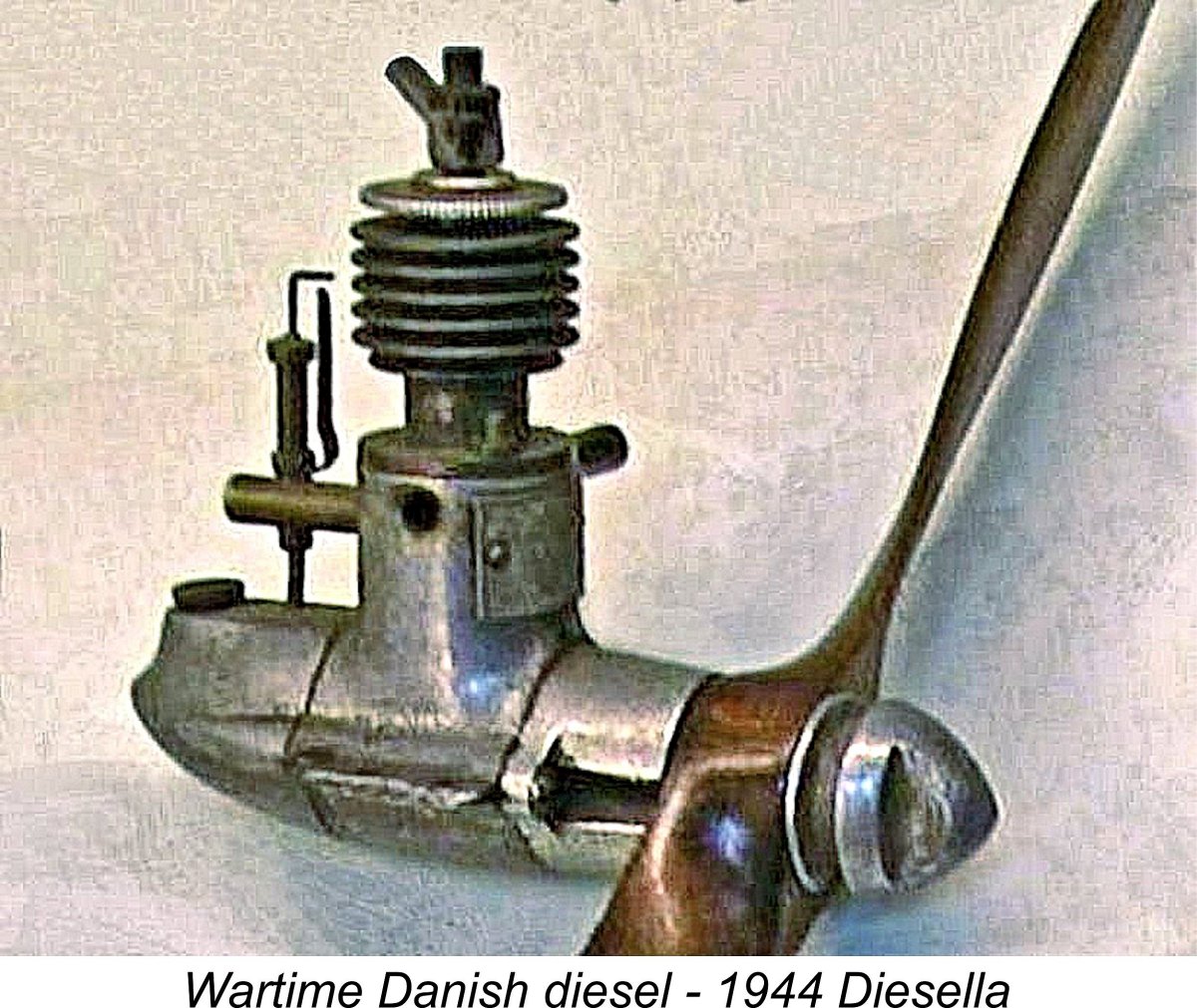 This new type of model powerplant underwent considerable development during the wartime years in European and Scandinavian countries which for one reason or another were not directly involved in the fighting. Even in those countries such as Italy and France which spent at least part of the war as battlegrounds, a considerable amount of development somehow took place. By the end of the war the model diesel had been developed in Europe and Scandinavia into a formidable competitor for the “traditional” spark ignition models.
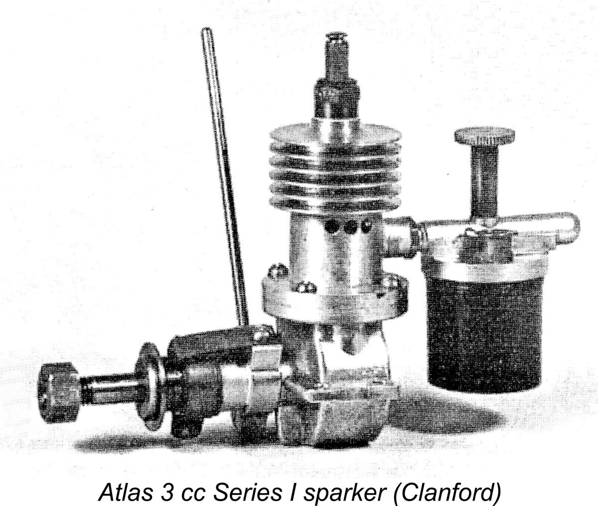 The September 1944 lifting of the wartime ban on the operation of powered model aircraft had already paved the way for a significant post-war upswing in the popularity of power modelling in Britain. An additional factor was the greatly enhanced level of “air mindedness” which had been fostered by the major role played by the Royal Air Force and the allied Air Forces in winning the war. Aeromodelling was on a roll!
 In response to this demand, a number of British model engine manufacturers were quick to get off the ground (hopefully!) with new spark ignition offerings. Among these manufacturers were
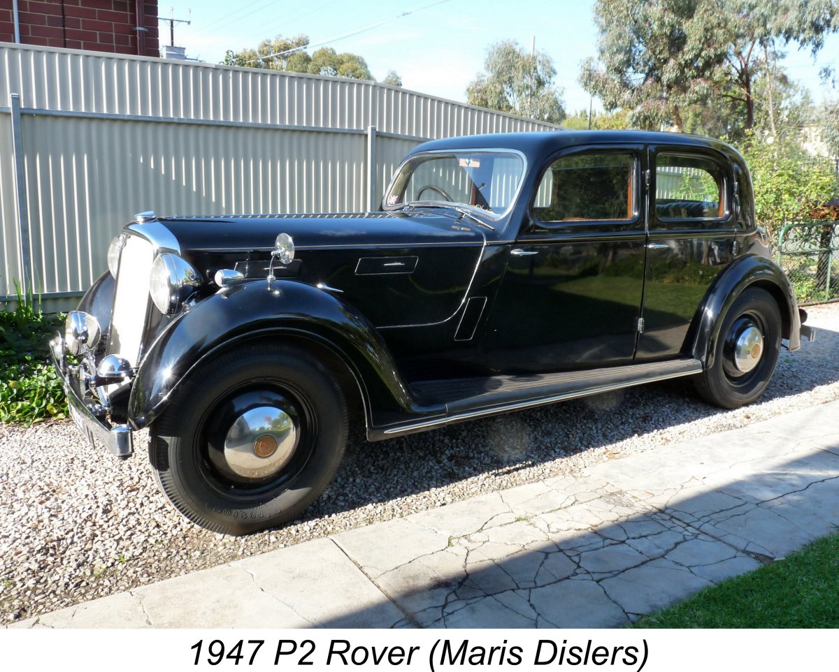
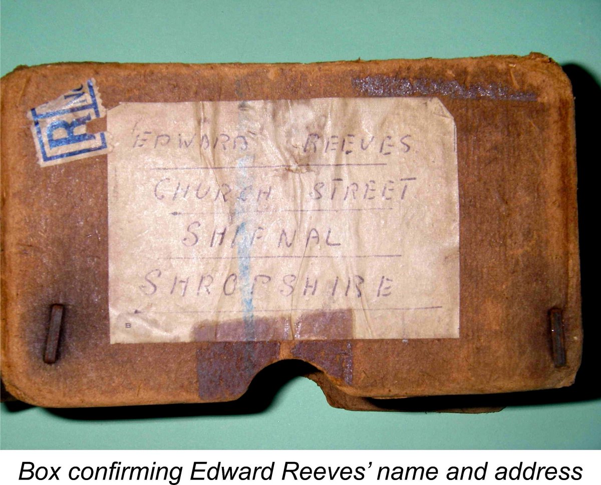
 It appears that all of the Reeves 6 cc models were manufactured at the Church Street location. The move to nearby Victoria Road seems to have come at some point in time after July 1947 since the previously-mentioned box in which the 6 cc engine was returned to Reeves for service was directed to Church Street. Exactly when the move took place thereafter is unclear, but it must have been completed as of 1949 if the later advertising is anything to go by.
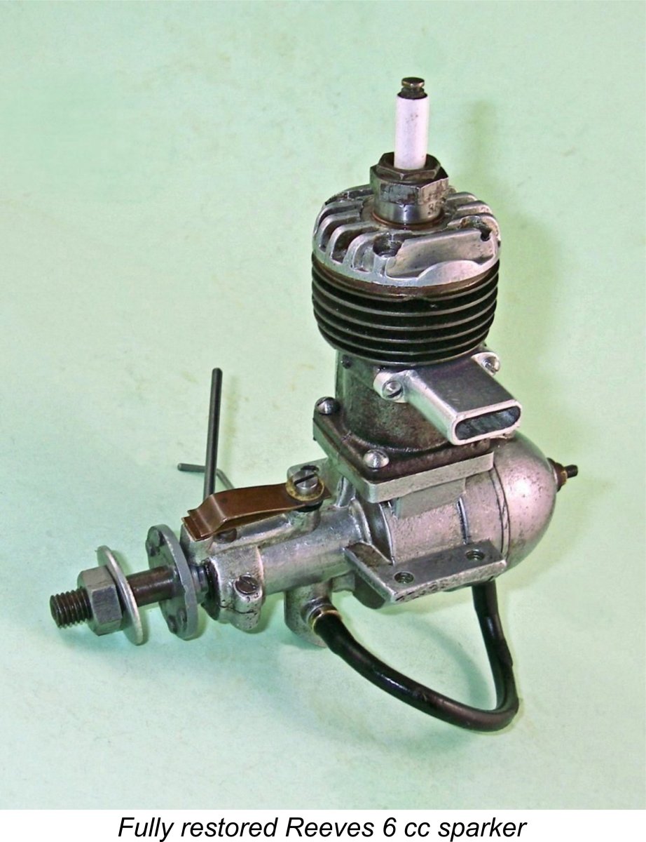
 When I wrote the original text of this article which appeared in October 2019, I had only one example of the Reeves 6 cc model - a Mk. II unit in excellent condition. However, in 2022 I was fortunate enough to be granted the opportunity to acquire a very nice complete example of the Mk. I variant. Accordingly, I'm now in a position to describe both versions with a great deal more authority.
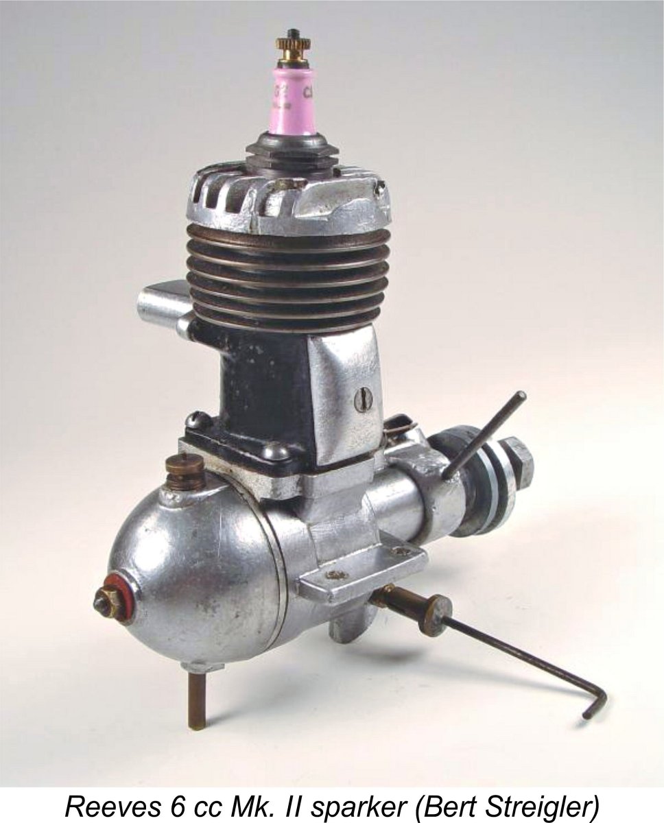
 The nominally 6 cc model was identified as having bore and stroke dimensions of
 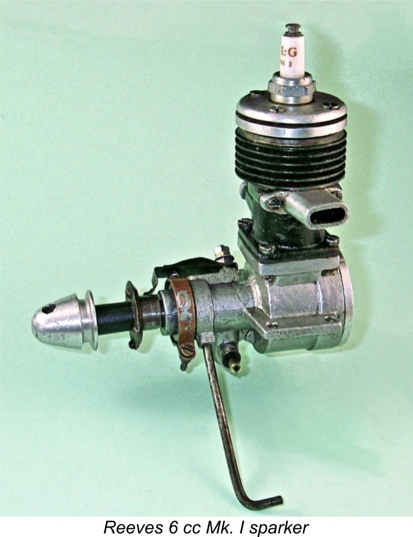 plug operation. Again, there appears to have been some variation between different examples. Maris's figure is most likely a reflection of the shorter stroke of his Mk. II example, which would of course place the piston crown slightly lower at top dead centre.
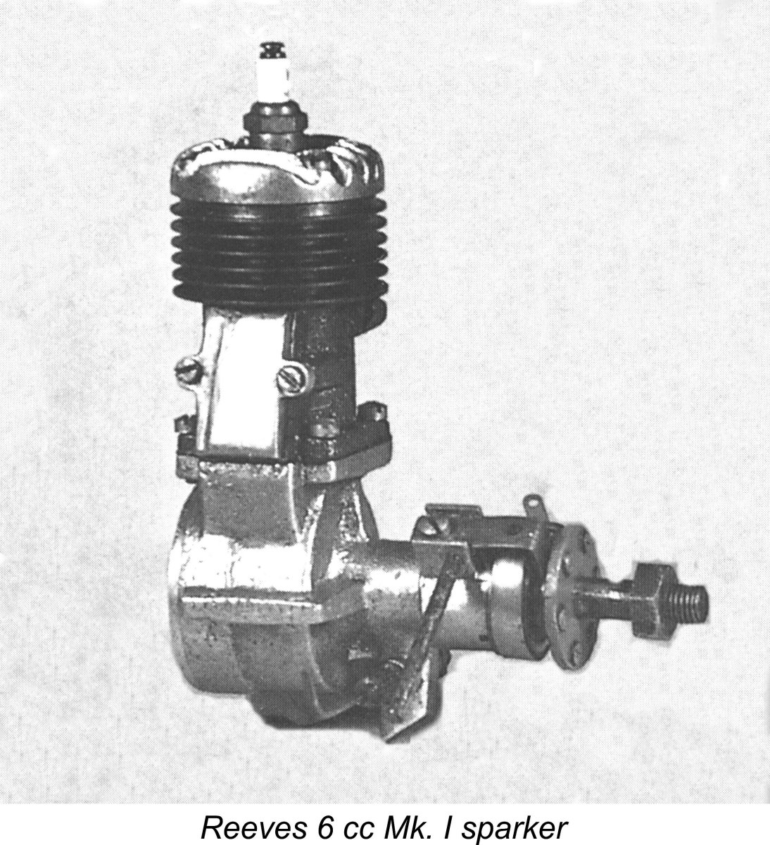
 The Mk. I variant uses a stamped and machined steel prop driver with the cam consisting of a flat machined into the rear section. The driver is keyed to the shaft using an internal slot which engages with a pin inserted part-way through the shaft - rather like a circular Woodruff key. The Mk. II's prop driver is cast from what appears to be a very hard form of alloy of some kind. It incorporates the cam in its reduced-diameter rear portion.
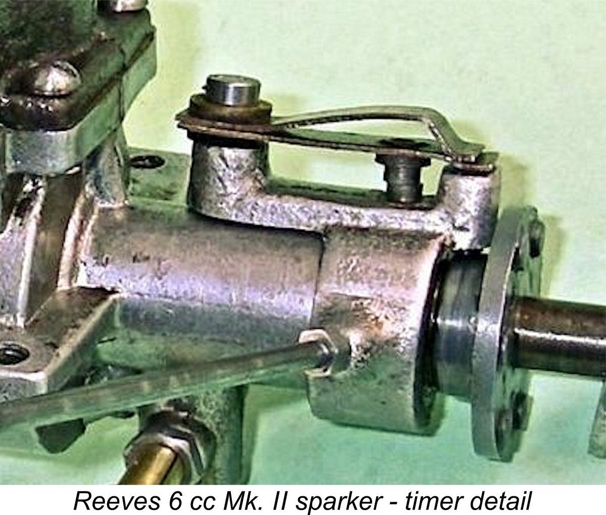
 I engine is located directly opposite the points, hence being oriented vertically downwards during operation.
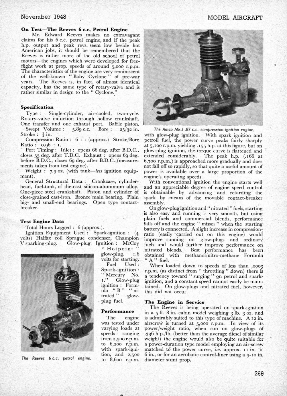
 Other than that, the engine’s excellent internal condition meant that no mechanical refurbishment was required apart from the making of a prop driver and the fitting of a suitable needle valve assembly. All that was otherwise necessary was the replacement of all screws and gaskets with fresh components. The addition of an original O&R
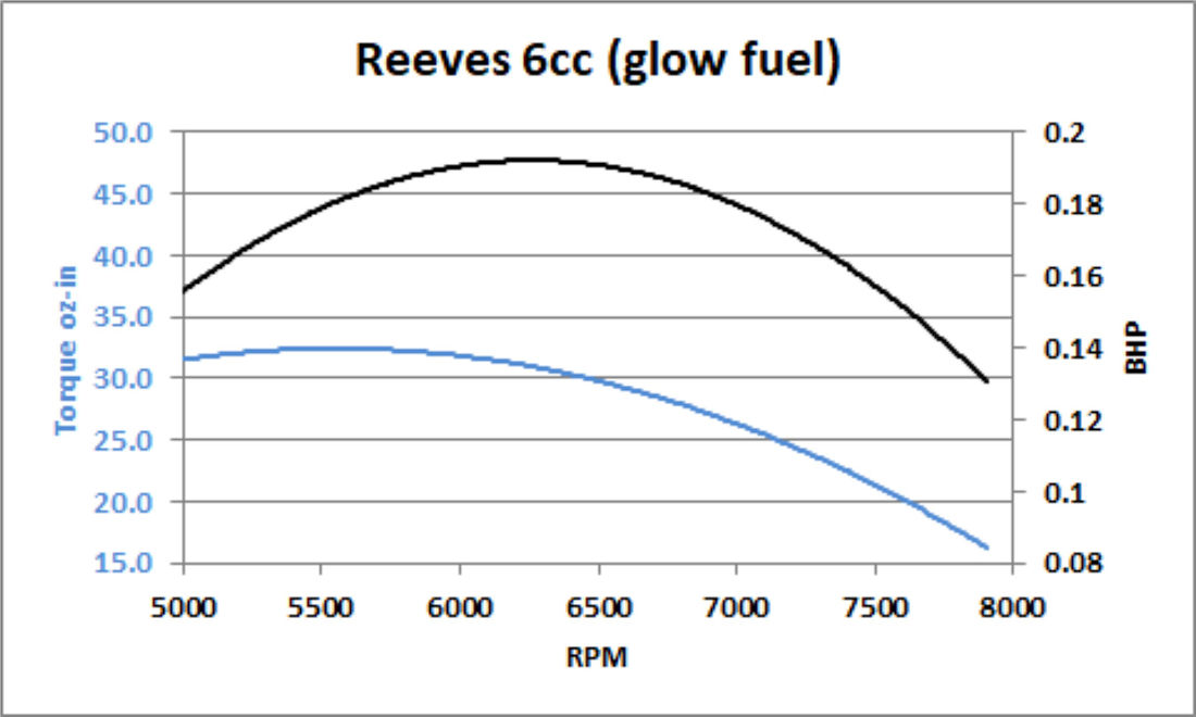
 I ran into a couple of immediate problems in getting this test underway. Firstly, I found that the back tank wasn't really suitable for bench-testing the engine because the updraft intake confined it to providing gravity feed. The fuel simply dripped continuously out of the updraft intake without any getting into the engine. It would appear that the fuel system was designed to work with the engine inverted - a very popular configuration among British model fliers at the time, as stated earlier. The updraft intake is entirely consistent with this theory.
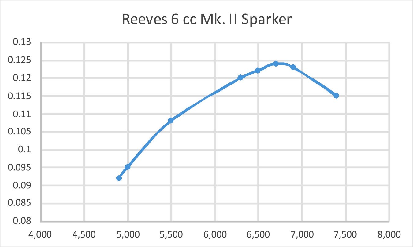
 It's noteworthy that my engine running on spark
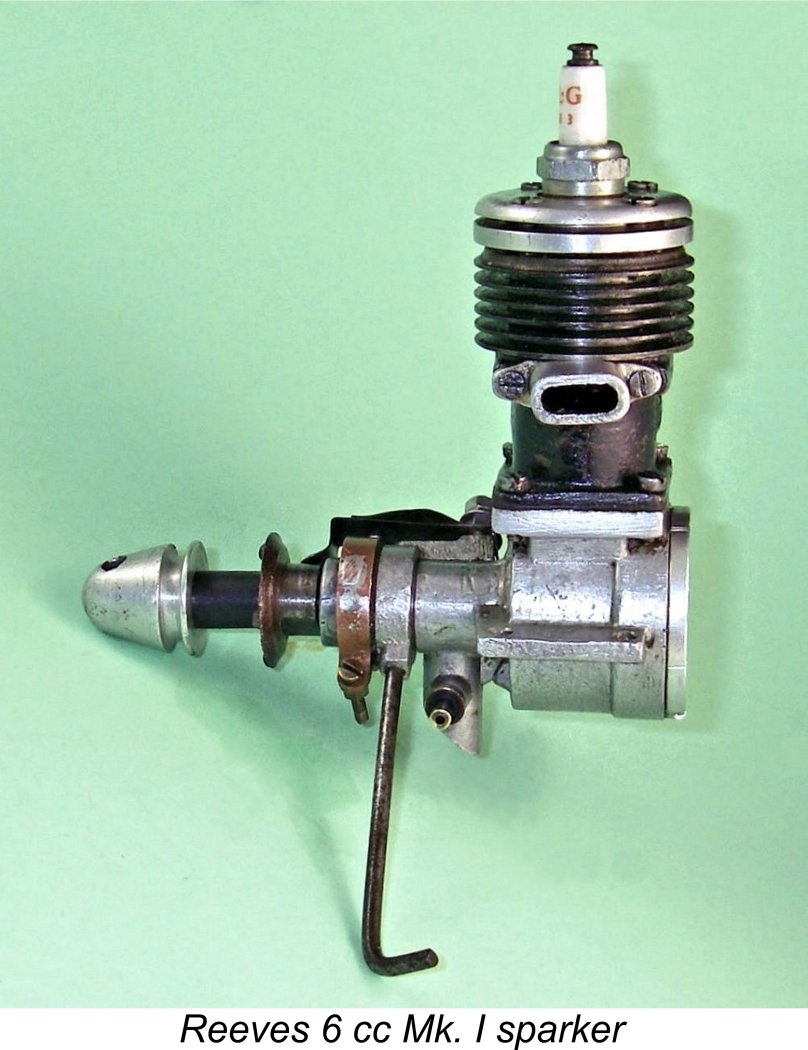
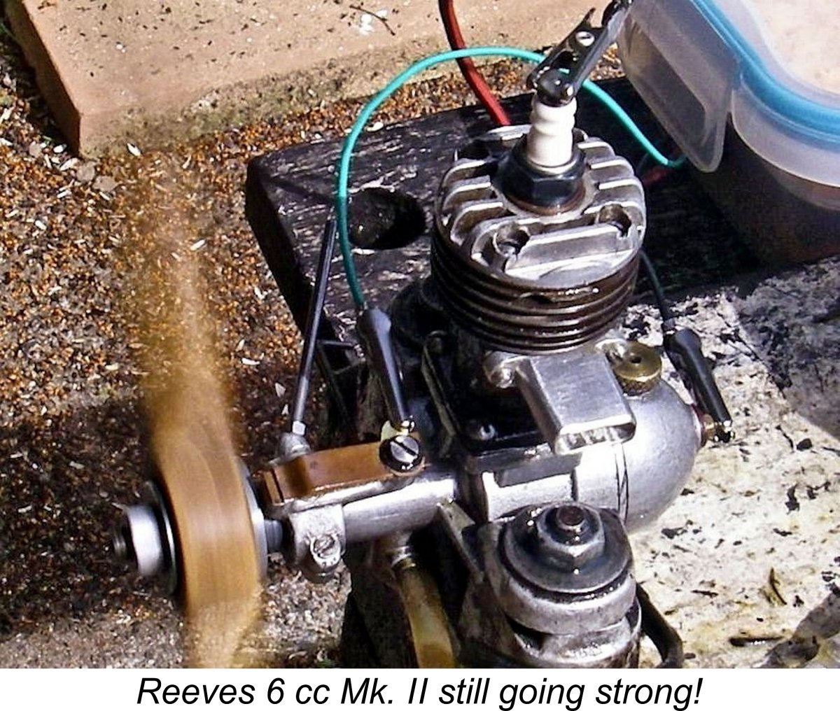
| |