
|
|
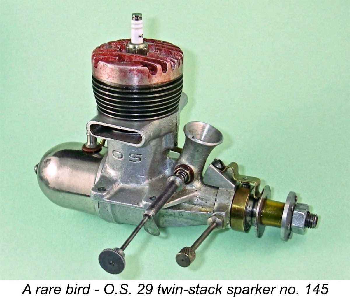
A Forgotten O.S. Design - the 29 Twin-stack Spark Ignition Model
At the time of their conception, the twin-stack O.S. models represented a significant departure from the design course which had previously been steered by O.S. designer Shigeo Ogawa. In fact, by then-contemporary Japanese standards they were very radical designs indeed. The question of how this highly distinctive design approach came about has always intrigued those having an interest in Japanese model engine history. Before delving into this and other aspects of the O.S. twin-stack story, I must acknowledge the assistance received from my English correspondent Alan Strutt in the preparation of this article. While I accept full personal responsibility for all of the data and interpretations set out herein, I relied very much upon Alan to read through what I'd written and challenge my conclusions every step of the way. Alan's assistance was much appreciated. Now, in order to understand how this engine’s brief existence came about at all, it’s worth summarizing the history of the O.S. enterprise. So here goes …………………. Background
By comparison with other Japanese model engines, the O.S. range is quite well documented. An excellent source of information on the O.S. marque is to be found in the Shigeo Ogawa entry at the ever-informative Internet Craftsmanship Museum. Another very useful reference is the late Peter Chinn's article on the history of O.S. to be found in the February 1959 issue of “Model Aircraft” magazine. Finally, O.S. themselves created and maintained a most informative pictorial history of their entire model engine range which was freely available online. The blue-background images below were extracted from the O.S. website with my grateful acknowledgement. For reasons which are unclear the company discontinued this very much appreciated feature of their own website for some time. It has now thankfully been updated to 2020 and re-instated. The updated version may be viewed here. Even so, one of the things that sets the O.S. twin-stack sparker apart from other O.S. models is the fact that although perhaps as many as two hundred examples appear to have been produced (see below), the engine does not appear in the O.S. timeline listing. We're on our own when researching this engine!
In 1936, while still in his teens, Ogawa somehow scraped together enough money to buy a lathe and drill press. The lathe was reportedly purchased for 100 yen (around US$29.00 at the then-prevailing exchange rate)! Using this very basic equipment, Ogawa began making model steam engines and live steam locomotives, an interest which he was to maintain throughout his working life. By this time he had become a skilled machinist. In that same year of 1936, Ogawa made his first model internal combustion engine, a 1.6 cc (0.10 cuin.) side-port spark ignition job which he initially installed in a model boat. The little engine performed so well that other Japanese modellers who saw it in use were sufficiently impressed to ask Ogawa to make copies for their use also. He was also encouraged by an American contact, one Paul Houghton, who was then resident in Japan in his capacity as a buyer of Japanese goods for an international trading company. With Paul Houghton's encouragement, a few more examples of this engine were made during 1936 and distributed to a small circle of Japanese and American modellers. The majority of these were put to model aircraft use.
The first O.S. design to be put into commercial series production was the neat little .10 cuin. displacement sideport unit which had been Ogawa’s initial design effort in 1936. It was released in 1937 as the O.S. Type 1 model. An impressive aspect of this development was the fact that Ogawa was still only 20 years old at this time! The O.S. Type 1 was very well received - in fact, some 200 examples reportedly ended up being exported under the overseas brand-name "Pixie". Production of this engine was initially restricted to around 20 units per month - a very far cry from the scale of things to come! However, the continuing positive reception of this engine soon encouraged Ogawa to expand his fledgling range beginning later in 1937. By 1941 he had designed and put into limited production a series of spark-ignition engines covering no less than six additional displacement categories from 4.4 cc (.27 cuin.) up to 9.5 cc (.58 cuin.). These included an impressive three-cylinder unit intended for marine use. With the ongoing encouragement of Paul Houghton, Ogawa even succeeded in getting a few of his engines sold in the USA, no small feat for a fledgling Japanese manufacturer at a time when American engines were the acknowledged world leaders. The Ogawa enterprise was well on its way!! However, on December 7th, 1941, Japan began its involvement in WW2 by attacking Pearl Harbour. That unhappy event naturally put the brakes on Shigeo Ogawa’s model engine development activities - international trade opportunities ceased immediately and in any case his production capabilities were needed for other purposes. He did manage to produce a very few examples of several 9.43 cc models during 1942 and 1943. These were probably used for the most part by trainee Japanese military fliers, who were apparently required to build and fly powered model aircraft as part of their training. However, at that point the tide of the war resulted in Shigeo Ogawa being conscripted into the Japanese military. His relatively weak physique fell short of meeting requirements for combat service, but the fact that he held a driving license (apparently a somewhat unusual qualification in Japan at the time) led to him being assigned to front-line service as a driver in the engineering corps. Accordingly, it was not until the Fall of 1945 that he was able to resume commercial model engine manufacture.
A proportion of those US service personnel were of course modellers in their spare time, creating an obvious target customer base for producers of model engines and related products. Every American military base had its own hobby shop, offering a potentially remunerative commercial opportunity for Japanese manufacturers to attempt to exploit. Indeed, these shops were officially encouraged to sell Japanese-made goods to assist in the rebuilding of the post-war Japanese economy. I love connections, and here's a fascinating one for you! Among the many Japanese entrepeneurs who applied themselves to the tapping of this new market were Soichirio Honda, Kenichi Mabuchi and our friend Shigeo Ogawa. Don Howie has conveyed his understanding that these three individuals became well-acquainted with each other through their joint service in WW2. Don Howie gathered that while getting his motorcycle business underway, Soichirio Honda actually made the beautifully-produced crankcase dies for these early post-war O.S. engines, thus assisting his wartime buddy Ogawa. As is well known, Honda quickly established what became the world's leading motorcycle manufacturer, while Mabuchi founded the famous Mabuchi Motor company which became the world's largest producer of small electric motors, many of which were used in models. Mabuchi was a keen model aircraft enthusiast, having won at least one major pre-WW2 competition.
The O.S. Type 10 was further refined with an updated 9.3 cc model later in the same year, followed by a revised 9.85 cc design in 1947. Spark ignition was naturally retained in all of these models - the commercial miniature glow-plug had yet to appear, nor had diesels yet penetrated the Japanese aeromodelling scene. It was also in 1947 that the first of several O.S. model pulse jet engines appeared in commercial form. As 1948 rolled around, we finally come to the point in time at which the low-production sand-cast twin-stack .29 cuin. spark ignition model which is the main subject of this article made its brief appearance. This was the precursor of the famous .29 cuin. twin-stack glow-plug models which began to appear in the following year and were later to be developed into companion twin-stack models in other displacements as well. As such, it is a significant design which is well worthy of full documentation. Despite this, the engine is conspicuous by its absence from the O.S. company's own timeline document to which reference was made earlier. Interestingly enough, it is not alone in being omitted - the 1951 O.S. "Bee" 1 cc diesel which was the company's first diesel model was similarly ignored or overlooked. When compared with other contemporary Japanese productions, it's an undeniable fact that the O.S. twin-stack models have a somewhat "un-Japanese" style about them by the standards of the late 1940's. Japanese design thinking at the time in question was very functionally oriented, with a distinctly minimalist slant - only those features which contributed to efficient operation were generally included. Some features of the O.S. twin-stack models appear to run directly counter to this philosophy in that they seem unnecessary from a functional standpoint (for example, you don't need twin stacks on a radially-ported engine!), hence appearing to be based more on "artistic" considerations. The engines certainly display a more exotic style than most of their rather utilitarian Japanese counterparts.
Most of the preceding information is of course common knowledge among well-informed model engine enthusiasts. What appears to be far less well known is the fact that these die-cast glow-plug models were preceded in 1948 by a sand-cast twin-stack .29 cuin. spark ignition design. This original twin-stack variant has remained more or less anonymous over the years because it was made in very small numbers indeed by O.S. standards - so small in fact that it was omitted from the previously-cited model summary leaflet prepared by the company in 1976. Examples are very rarely encountered today. I've already written about this previously undocumented engine in an earlier article which may still be found on the late Ron Chernich’s now-frozen but still wonderful “Model Engine News” (MEN) website. So why write about it again here, you may ask? Mainly because when I wrote the earlier article, I had not yet mastered the techniques or assembled the equipment required for testing spark ignition engines. Hence that earlier article did not include a test report. Happily, I’ve now equipped myself to conduct complete bench tests on spark ignition units, as recorded in my detailed article on spark ignition operation which may be found on this website. Consequently, I’m now able to present an actual running test of the engine. But first, a description of this elusive sparkie seems to be in order. Description
My own example formerly belonged to the late Clarence Bull, a once well-known old time American modeller who ultimately became best known for his excellent BY&O wood propellers. Clarence had reportedly had the motor for many years, and I'm extremely grateful to my friend Mike Conner for providing me with the opportunity to acquire this very rare engine! Apart from the obvious presence of a timer, the most immediately observable difference between the spark ignition version of the twin-stack O.S. 29 and the later glow models is that the sparker is based upon a sand-cast crankcase as opposed to the die-cast components employed on all of the subsequent twin-stackers. The twin exhaust stacks on the sand-cast case were cast solid and then milled out internally. They are missing Another visible difference is the fact that the sparker has a screw-in backplate as opposed to the bolt-on component employed on the subsequent glow versions. Finally, the tank of the spark ignition model is plated rather than being color-anodized. Upon first examining the motor, it was immediately clear that this was something very different - inquiries were definitely in order! The appearance of the O.S. name cast intaglio into the right-hand side of the main casting confirmed the engine's claim to be an O.S. product, even if the design itself had not already done so. Contacts with friends and colleagues in Japan yielded confirmation that this is a recognized O.S. model among Japanese collectors although it is extremely rare today even in Japan, where little is evidently known of its origins. The “word on the street” among old-timers in Japan is that at most some 200 examples of this sand-cast spark ignition model were produced in 1948 as a prelude to the decision being taken to enter into series production of the die-cast glow-plug version in 1949. Basically, the sand-cast spark ignition model is viewed in Japan as having served as a test-bed for the generic O.S. twin-stack design. This characterization has the ring of truth about it, as we shall see. The engine is encountered with both plain and red-anodized cylinder heads. My Japanese contacts speculated that the red-anodized head may have been a high-compression option. However, the checked compression ratio of my own red-anodized example is a very modest 6.5 to 1, which is a perfectly appropriate figure for a moderate-speed general-purpose spark ignition engine running on gasoline but hardly supports the high-compression theory! It seems more likely that the heads are identical and the red anodizing was introduced on a batch of the later examples purely as a cosmetic improvement. Perhaps those (like my example) that went to the USA were so treated. Both styles of head are centrally tapped to accomodate a 1/4-32 plug.
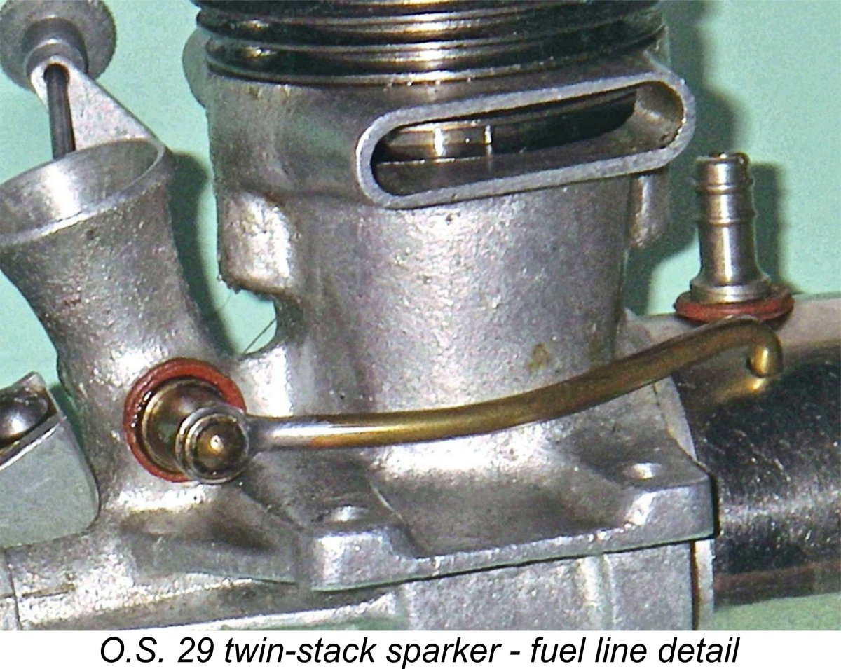
The fuel line is the ubiquitous 2 mm brass item typical of those used on many Japanese engines of this vintage. It appears that flexible plastic fuel tubing still retained its early post-war scarcity in 1948 Japan. The needle valve assembly with its externally-threaded needle is also typical of contemporary Japanese practice. It is fitted with a flexible extension and a locating clip that could be bent to fit over the rear mounting hole or be attached with a screw to the airframe. A simple coil spring is used to retain settings. I noted above that unlike the later glow models, the backplate is a screw-in item which is machined from a sand-casting. The interesting side observation may be made at this point that when the Japanese manufacturers of the Boxer engines released their .29 cuin. twin-stack glow-plug model, which gives the appearance of having been closely modeled on the O.S. 29 albeit with somewhat more "Japanese" styling, they used a screw-in backplate of similar pattern to that seen on the spark-ignition O.S. 29 twin-stack. It's actually possible that the Boxer glow model preceded the 1949 O.S. glow version—we don't know for sure. I've covered the Boxer range in detail elsewhere on this website.
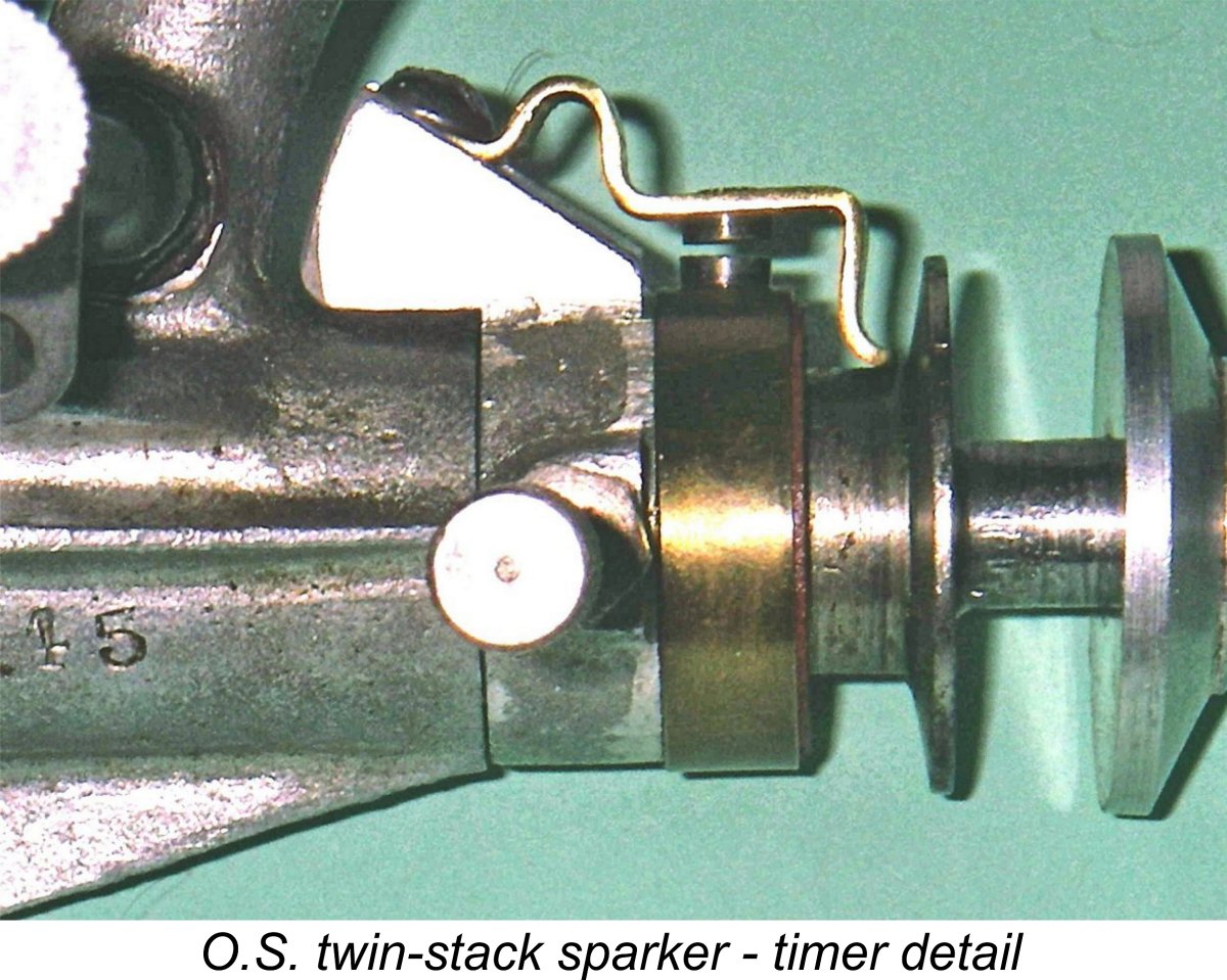
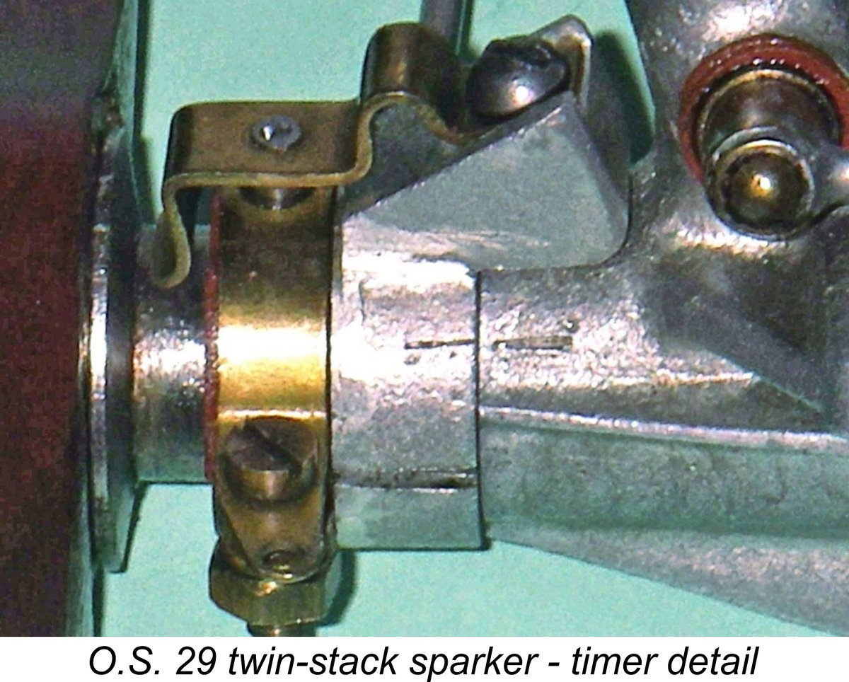
Following the removal of the fuel system, the next step was to unscrew the very substantial sand-cast backplate. This revealed a crankweb that appeared very similar to that of the later glow models. The cast alloy rod is clearly different, though—it is a very sturdy item with cast-in webs at the rear and a bronze bushing at the big end. A lot of hand-work appears to have been done to finish it after casting. The cylinder assembly is retained by only two screws which pass through the sand-cast head and integrally-formed steel cylinder cooling fins to engage with tapped holes located fore and aft in the case. There are two additional screws at the top to help to retain and seal the cylinder head. These thread directly into the upper flange of the steel cylinder. A nice touch is the fact that all four screws have locking washers installed under their heads. I removed all screws but left the head in place since it seemed to be well "stuck" on and I didn't want to break a good seal. The screws have a rather oddball metric thread of 3 mm x 0.65 mm—a slightly coarser thread than standard 3 mm items. I'd best not lose them!! Maris Dislers has pointed out that these screws were almost certainly threaded to the old and now long out-dated JIS (Japanese Industrial Standard) metric specification. These threads were basically similar to the old DIN and French thread forms that preceded the now widely-used ISO metric thread standard which was one of the first International standards agreed upon when the International Standards Organization (ISO) was established in 1947. Maris believed that the ISO threads only came into general use in around 1965, at which time O.S. apparently dropped the JIS threads and went to the ISO standard. Oddly enough, Enya continued to use the JIS fasteners for far longer, right up to the Enya 11CX with its unusual crankshaft thread and those seemingly coarse 3 mm screws for retaining mufflers on the cross-flow engines. That said, up to now I have been unable to gain access to a thread data chart for those old JIS fasteners. The cylinder arrangement is more or less identical to that used later on the die-cast twin-stack 29 glow models. The exhaust port flange sits on a recessed shelf machined into the upper crankcase casting just The very heavy counterbalance on the crankweb necessitates the use of an asymmetrical rod. As can be seen in the side view of the rod, the actual rod column is located well to the rear of the big end bearing centre. The big end is bronze bushed and the small end is of very generous length, occupying most of the exposed width of the gudgeon pin within the piston. The piston has a conical top with no deflector, matching the plain conical configuration of the underside of the cylinder head. Unlike the pistons of the later .29 and .36 cuin. glow models, which used a separate gudgeon pin carrier riveted into the piston interior through the piston crown, the sparker employs a conventional fully floating gudgeon pin mounted in bosses formed integrally with the piston in the conventional manner. The gudgeon pin itself is a tubular steel item having brass end pads. The piston walls are rather thin and there is no increase in wall thickness at the boss locations. As a result, the bearing length for the gudgeon pin ends in the bosses is minimal, to the point where this may legitimately be considered a design weakness in my personal view. The crankshaft is generally similar to that of the later glow model apart from the fact that it has a far shorter The prop-nut thread on the crankshaft was originally 7 mm, but unfortunately on this example a previous owner has re-cut most of the thread to 6 mm. This rather botched effort can be seen on the accompanying image of the crankshaft. Fortunately, it doesn't affect the engine's appearance or functionality in any meaningful way. By far the oddest feature of this model is the timer design employed. As can be seen in the images, the timer is a simple axially-oriented leaf-spring open-frame device of a pre-WW2 type that had been abandoned by O.S. and others for a considerable time prior to 1948, when the twin-stack sparker was Although very well executed with a sturdy cast frame, the type of timer fitted to the twin-stack spark ignition model presently under discussion is rather rudimentary and would almost certainly have represented an impediment to the extraction of maximum performance. The point gap, for instance, is not readily adjustable. The sole advantage of this unit is its ease of maintenance—everything is exposed for convenient inspection and cleaning. We might suppose that perhaps Ogawa-san just liked the retro look of that timer style and appreciated its maintenance advantage. That is certainly a possibility, albeit in my view rather unlikely and certainly very "un-Japanese". Another possibility of course is that my Japanese colleagues have their dates wrong and the engine actually dates from well prior to 1948. This again seems highly unlikely - the engine bears no design resemblance whatsoever to any of Ogawa's pre-war, wartime or early post-war designs. There's no doubt that it is best seen as a direct precursor of the twin-stack glow models which began appearing in 1949, and this is completely consistent with the reported 1948 date noted above. When considering the potential design operating speed of a spark ignition engine, a further design parameter that needs to be factored in is the dwell period provided by the timer. This is the angle of crankshaft rotation during which the points are closed and hence in direct electrical contact with each other, thus supplying current to the ignition coil's primary circuit. I've discussed this parameter more fully in my separate article on spark ignition engine operation. Since sufficient real time must be provided during each revolution to ensure full saturation of the primary coil winding before the points open to trigger the spark, the dwell requirement varies from engine to engine, the main factor being operating speed. A relatively slow-speed unit like a Brown Junior, Atom .099, Bunch, Elf or even an early Ohlsson can operate successfully with a relatively short dwell period of 50 – 60 degrees or even less. The O.S. sparker appears to fall into this category. A short dwell period conserves the life of the flight batteries, since it minimizes the proportion of running time during which the points are closed and current is flowing to the coil from the batteries. For the same reason, it tends to protect the coil from any tendency to overheat. However, it also makes the engine more susceptible to ignition problems resulting from point "float" – an inertia-caused delay in responding to the retreating cam surface when the points close. In addition, it limits the maximum speed at which the engine can be run because a speed will be reached at which there's insufficient real point contact time during each revolution for the coil to become electro-magnetically saturated, as it needs to be to provide a good hot spark.
One interesting detail in connection with the timer is the presence of a pair of inscribed timing marks on the timer body and crankcase respectively. These marks are clearly visible in the attached image of the timer. When aligned as depicted by rotating the timer, these proved to be perfectly located to set the ignition timing correctly for easy starting. A thoughtful touch to assist users of the engine. These observations lead directly to a consideration of the possible circumstances under which this very rare engine had its genesis. Let’s look at that issue next………… Possible Origins The apparent incongruity of the timer design on this engine seemed to offer a promising avenue of research into the origin question. To initiate this research, I decided to look for an answer to the timer question that had some basis in terms of practical considerations while also fitting the surrounding circumstances. A good start appeared to be to wade through the various publications on model engines which included illustrations of the timers of a variety of engines to see if any external design influences were apparent.
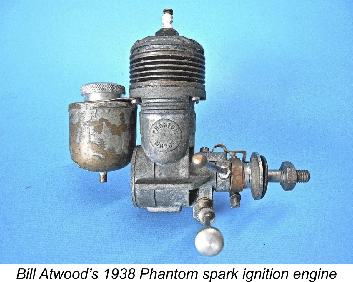
Suddenly, things began to fall into place!! The implication is that the source of the very "agricultural" timer was none other than Bill Atwood! This is completely consistent with the previously-established fact that Atwood had a close connection with the O.S. twin-stack series. It now appears that Atwood may have become involved with the O.S. twin-stack project at an even earlier stage than had been suspected. Indeed, he may have even been the instigator and promoter of the overall engine design. If this was the case, Atwood may well have had a significant influence on the basic design of this model going right back to its initial spark-ignition configuration. Although I must stress that this is nothing more than informed speculation, it's undeniably difficult to explain the use of the decade-old Phantom-style timer on the 1948 O.S. spark-ignition prototypes in any other way.
The assembly screws for the timer measure up at 3 mm x .65 mm (0.118 in. x 39.07 tpi) - another non-standard metric thread which is a close approximation of a 4-40 thread (0.112 in. x 40 tpi) but doesn't work with a 4-40 nut - the nut tightens up well before the thread makes it through. As noted previously, the cylinder hold-down screws are of that same 3 mm x .65 mm thread - they do not fit into 4-40 holes, and 4-40 screws rattle about in the tapped holes in the case and would strip for sure if tightened. I've mentioned Maris Dislers' very plausible theory that this is an example of one of the long-discontinued JIS threads - perhaps that weird 2.3 mm x .55 mm thread is also an example. The best practical scenario that I've been able to come up with to explain all of this (and I freely admit that it's pure speculation based on circumstances) has Ogawa and Atwood in 1947 discussing the possibility of Atwood assisting in the marketing of a suitable introductory O.S. product in the USA. It's worth recalling at this point that O.S. had in fact succeeded in selling a few engines in the USA prior to WW2 getting in the way. So this scenario would have made perfect sense in the context of an attempt by Ogawa to resume a commercial activity that had been rudely interrupted by the war. And we already know that Atwood did assist Ogawa on the post-war marketing side in the USA. So far, so good............. At the time in question, the US market was well supplied with excellent domestic engines (by Atwood himself, among others) in the larger displacements on which Ogawa had focused immediately following the war. The emerging trend was in the direction of smaller engines, and Atwood may have suggested that Ogawa would do better to try something a little smaller. He certainly wouldn't have suggested a design that would compete with his own offerings! Inevitably, the very popular .29 cuin. displacement category would have come up. But even this category was well supplied domestically in the USA, albeit not at the time by Atwood, who may well have suggested that Ogawa needed something visually "different" with which to woo the US consumer. The strikingly artistic but rather “un-Japanese” twin-stack .29 cuin. design could well have resulted from such discussions. There's no way of knowing whether Atwood or Ogawa was the primary designer - there are objections to both possibilities. But someone undoubtedly came up with the twin-stack concept, and Ogawa undeniably ended up producing a series of such engines. I think that the most probable (albeit currently unsubstantiated) explanation for the existence of this engine is an agreement between Atwood and Ogawa to collaborate in the manufacture of a short run of such engines on mutually-agreed design lines and then to try them out on a sample of their intended customers both in Japan and in the USA. This may well be how Clarence Bull (who knew Bill Atwood personally) came to own the example that now resides in my own collection. The extent of any collaboration that may have taken place in connection with the actual manufacturing is unclear, but it seems likely that Atwood supplied the timer components at least. It might be asked why Ogawa would sit still for the use of such an antiquated timer on the newly-conceived twin-stack wunderwerk that bore his company's name. It seems probable that he saw this engine as more of a test piece than a production model in the true sense. This would explain its omission from the company's subsequent listings of their commercial products, an omission which is otherwise difficult to rationalize. Ogawa may well have seen the engine as an Atwood initiative rather than his own, hence being content to let Atwood fit whatever timer he liked. If the engine failed in consequence, that would reflect on Atwood rather than Ogawa.
In the latter context, Ogawa most likely foresaw that any production model which might result would use glow-plug ignition but was stymied for prototype testing purposes by a chronic unavailability in Japan of suitable glow-plugs at the time. It must be recalled that in 1948 platinum-iridium wire for making glow-plugs was in the unobtanium category in Japan - whatever was available came from American service personnel like Jerry Asner, who supplied wire to Enya and Fuji and later became Enya's first US distributor. To compound this problem, Ogawa was a bit out of the mainstream anyway down in Osaka and might have had trouble accessing any glow-plugs that were available. So at the time of which we're speaking, the use of glow-plug ignition for the test prototype series might have presented a bit of a problem for him (although that had certainly changed as of 1949). This view is supported by the fact that all of the other O.S. models being produced as of 1948 were still spark ignition units. However, as of 1948 the other O.S. spark ignition models with their up-to-date enclosed timers were all much larger engines in the .60 cuin. neighborhood, and the timers used on those models would not readily fit the smaller .29 cuin. model now envisioned. The same was true of Atwood's then-current productions. This would have created a bit of a dilemma for the design team. As of 1948 the glow-plug had definitely arrived in the USA, and it's highly probable that neither Atwood nor Ogawa saw any long-term future for the use of spark ignition. This being the case, they would be understandably reluctant to go to the trouble of developing a new purpose-built .29-size timer. Indeed, Atwood was already poised to move into the glow-plug era himself with the 1948 Glo-Devil version of his .63 cu. in. Super Champion design as well as glow-plug versions of his new Triumph models. However, Atwood had a solution to the immediate problem at hand - use a slightly modified version of the old Phantom 29 timer with which he was so familiar. Although he no longer made .29 cuin. spark ignition engines and would have been just as reluctant as Ogawa to develop a new timer for a short-run test series, he probably still had a lot of the required components from the old Phantom series lying about. Moreover, he had extensive experience in making these things work.
If this scenario is correct, the likely expectation was that if the design looked promising Ogawa could then go to the expense of making dies and committing himself to a die-cast glow version once the glow-plug supply situation had become less of an issue. This is in fact what occurred in 1949. Having gone through the above scenario in detail, it's necessary to repeat once more that all of this is nothing more than informed speculation at present, being based entirely upon circumstantial evidence. I would need far more hard evidence before I could claim any of it as fact. I’d welcome any alternative scenarios from readers that are supported by other evidence or fit the above circumstances equally well. One objection that I myself can set against the above hypothesis is the seeming improbability of Atwood coming up with a design concept that was so far removed from his own previous design thinking. All of his earlier designs had followed a logical design progression which was deeply rooted in then-current American design thinking, albeit with some interesting twists on the induction theme. However, this seeming anomaly could perhaps be explained if Atwood wanted to try out a radical new design concept but wasn't sure how it would work out. In such a case, he may have been attracted to the idea of having his design concept tested by a different manufacturer in another country. Any failure of the concept would then be chalked up against the other manufacturer rather than Atwood. Still, there are objections regardless of whom one credits with the design. And the fact remains that someone undoubtedly did come up with it - choose your favorite!! However it came about, this is certainly one of the more intriguing and least-known O.S. designs from the early post-war period. The next question must surely be – how does it run?!? Let’s find out – after all, that was my chief motivation for writing this revised article!! The O.S. 29 Twin Stack Sparker on Test There was no doubt at all in my mind that this engine should run well despite its somewhat “agricultural” timer by 1948 standards - the component is both very well made and quite sturdy, with a very strong point-closing spring. If anything, the likely effect of this timer design would be to limit the maximum operating speed of the engine. For a spark ignition design with its adjustable ignition timing and consequent operating flexibility, low and moderate speed running presents no insuperable obstacle. The rather low compression ratio of the test engine certainly implies that its intended peak operating speed was not high.
I decided to begin my sparker test using a somewhat slower 10x6 prop, namely a Top Flite 10x6 Power Point wood item. For some reason it just seems more appropriate to test sparkies on wooden props! My plan was to try the faster APC 10x6 prop at some stage during the test to allow a direct comparison with the later glow-plug model. For this test I fitted a brand-new NGK spark plug which I happened to have handy – an all-Japanese test!! I used a standard gasoline-based fuel containing 3 parts of Coleman camp fuel (white gas) to 1 part of SAE 60 mineral oil (AeroShell 120). The compression ratio of only 6.5 to 1 is a bit marginal for operation on methanol, besides which it’s unlikely that methanol was widely available in 1948 Japan. Those who used these engines most likely ran them on low-grade gasoline. All test running was conducted using the engine's own back tank. The motor felt really good when set up in its test stand, although you could readily detect the rather low compression ratio when flicking the thing over – not much resistance, especially by my usual diesel standards! Still, piston seal was very good, so I expected no trouble. I ran the usual timer function checks, finding that everything was working perfectly, after which I set the timer to open the points (triggering the spark) at about 10° BTDC. Finally, I connected the necessary three wires (plug, points, ground) from my recently-constructed Larry Davidson SSIGNCO ignition support system (see my separate article on that subject) and got stuck in.
Running qualities were beyond reproach right out of the starting gate. The needle was particularly easy to set, not being excessively sensitive but with a very well-defined optimal setting – I could go either side with only a small drop in speed, making it very easy indeed to find the sweet spot. The timer control arm also produced the usual good response, with the best advance setting readily being found by experiment once the engine was running. It's exactly like adjusting a diesel using the comp screw. I found that the O.S. had all of the running characteristics of an excellent control line stunt motor. It would run slightly rich in a very steady four-stroke mode, with a well-defined break between four-stroking and two-stroking. When leaned out to the best needle setting, running was smooth and completely mis-free, with no tendency to sag. The engine turned the rather parasitic Top Flite 10x6 Power Point wood prop at a seemingly effortless 9,000 rpm and ran the tank out cleanly on that prop. I switched to the considerably faster Zinger 11x4 wood prop, expecting a marked speed increase. However, it didn’t happen – that prop only got up to 9,200 rpm. Moreover, a very slight crackling misfire had started to creep in. Since I was using fresh batteries, this implied either that I was nearing the limit of the timer’s ability to fully saturate the coil prior to spark generation or that the low compression ratio was beginning to show its effect. Contrary to expectations, it appeared that I had already passed the engine’s peak on these two props. Indeed, this proved to be the case. There was clearly no point in trying the even faster APC 10x6 as I had originally intended. Instead, I changed tactics by trying some slower props. This turned out to be the right way to go. Running became completely smooth once more, and the engine performed flawlessly. Starting remained very easy throughout. The following figures were recorded:
The sparker evidently produces considerably more lower-end torque, as we would expect from a spark ignition unit with its fully adjustable ignition timing. Moreover, I suspect that it would deliver a measurably stronger performance if operated on the same 10% nitro glow fuel used in the glow-plug test, The engine exhibited no signs of any mechanical distress throughout a fairly lengthy test, during which it did quite a lot of hard running. It remained in perfect mechanical condition at the conclusion of the test series, seemingly being ready to do as much additional work as might be asked of it. A very convincing demonstration of an engine of unmistakable quality! As a postscript to the above test, I can report that I subsequently had the good fortune to acquire a genuine antique O.S. spark plug of the type doubtless fitted to this engine back in the day. I hadn't realized that O.S. made their own spark plugs, so this was an enlightening acquisition! As a result of this stroke of luck, the engine is now reunited with a contemporary spark plug from the same maker. I haven't had the chance to try it with thus plug fitted, but I hope to find time to do so at some point in the future. Conclusion It appears certain that the O.S. 29 twin-stack sparker was never seen by its manufacturer as a potential production item. It was created rather too late in the day to have been seen in that light – the switch to glow-plug ignition was already well underway when it appeared. It actually appears to have been seen as a development prototype. This explains its omission from the O.S. company's own listings of its products. That said, the engine clearly served its intended purpose very well by demonstrating the underlying merits of the radical new twin-stack design approach then being developed at O.S., with or without the involvement of Bill Atwood. Its performance was certainly sufficiently impressive to encourage the manufacturer to proceed with the development of the subsequent glow-plug version which was probably the design goal all along. As such, it must be seen as a highly significant if hitherto undocumented design in the context of O.S. model engine history. ______________________ Article © Adrian C. Duncan, Coquitlam, British Columbia, Canada First published May 2020
|
||
 Most aficionados of classic model aero engines are doubtless familiar with the series of radially-ported reverse-flow scavenged twin-stack glow-plug models that were introduced by the O.S. company of Osaka, Japan beginning in 1949 (over seventy-five years ago - how time flies, especially if you're an aeromodeller!). There were two successive variants of the .29 cuin. version of this design, as well as an .099 cuin. model and a .36 cuin. unit that was specifically targeted at the American market. The various O.S. twin-stack glow-plug models formed a major component of the company lineup from 1949 until 1954, when the new loop-scavenged O.S. Max series first appeared.
 It’s astonishing how few of today’s modellers seem to be aware of the fact that the familiar O.S. trade-name enjoys a unique distinction which is highly unlikely ever to be superseded by any other - it has been continuously associated with the model engine market (and indeed with the model trade in general) for the longest period of time of any trade-name in modelling history. With each passing year, this respected Japanese company’s record of ongoing involvement in model engine production grows another year longer, and it seems inconceivable that any other manufacturer will ever surpass the production record of O.S., now deep into its second half-century and still going strong in today’s vastly changed marketplace. You have to be at least 88 years old as of the present time of writing (2024) to have lived at a time when O.S. model engines were not being manufactured!
 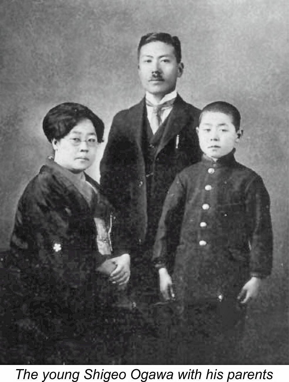 The
The 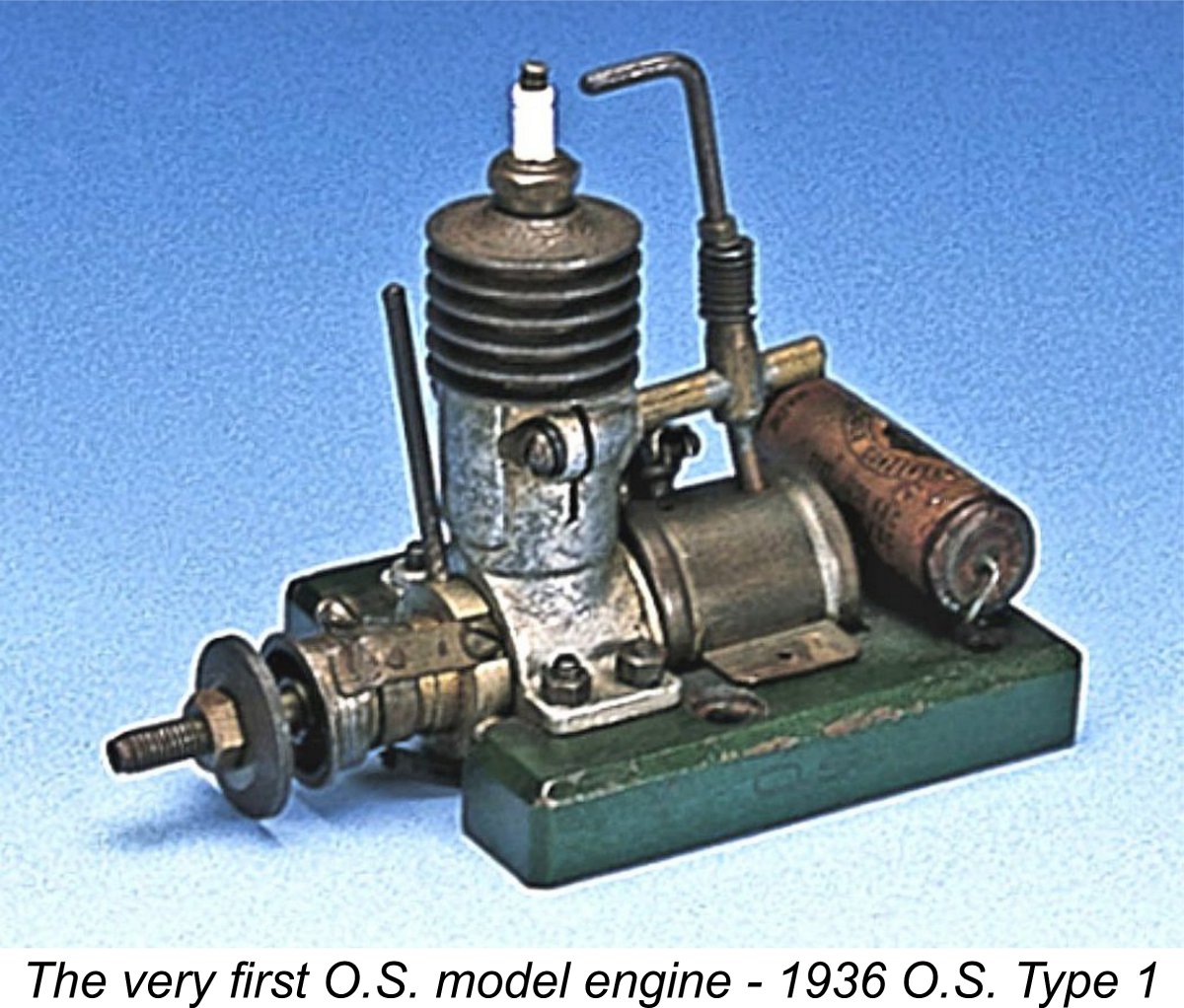 Ogawa-san’s initial efforts drew sufficient attention both from his fellow Japanese modellers and from others that in 1937 he was encouraged to initiate the small-scale commercial production of the first of what was to become a long line of O.S. model engines which continues to the present day (2024). The company trade-name arises from the fact that in the Japanese language the family name is always placed before the personal name - hence, the letters O.S. are simply Shigeo Ogawa’s initials placed in their Japanese order.
 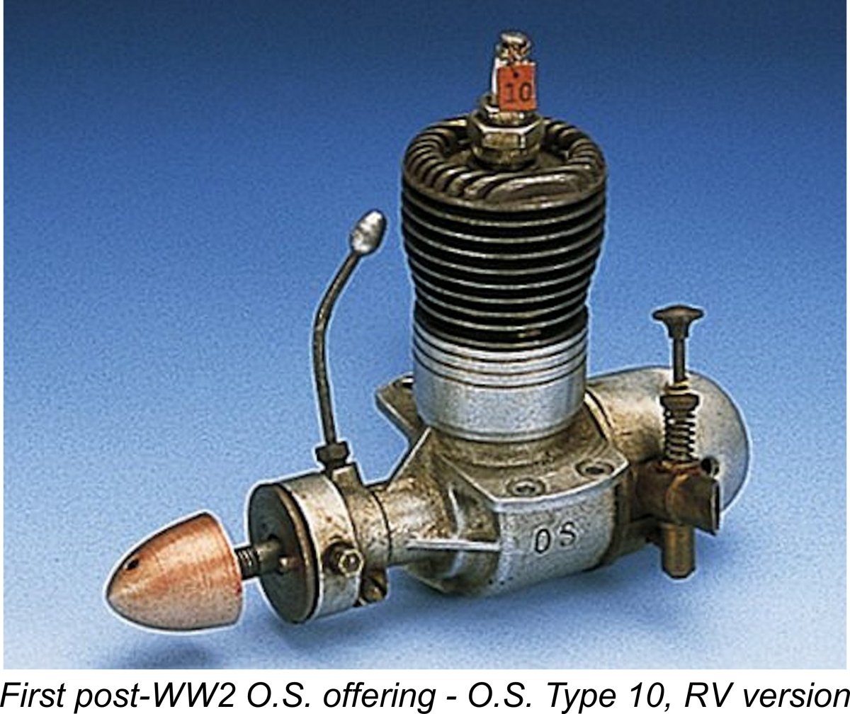 The conclusion of the war found large numbers of American service personnel stationed in Japan with the occupation forces. This created a sizeable market constituency with discretionary spending power far in excess of that of the average Japanese citizen in the war-ravaged early post-WW2 Japanese economy. In effect, there was no longer any great pressure to pursue exports to America - the American market had come to Japan!
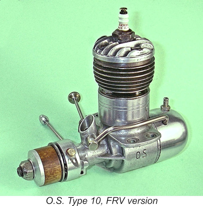 Taking full advantage of the opportunity presented by the massive post-WW2 American presence in Japan, the now 28 year old Ogawa lost no time in re-establishing his Osaka factory on a larger scale. By 1946 he was back in full production with a 9.7 cc model which was offered in both crankshaft front rotary valve (FRV) and rear induction (RV) forms - the O.S. Type 10. The example illustrated above is one of the RV models. I have a very nice example of the FRV version (right) which had been competently converted to glow-plug operation as received but has since been fully restored with a replica timer superbly made by my mega-talented mate Peter Valicek.
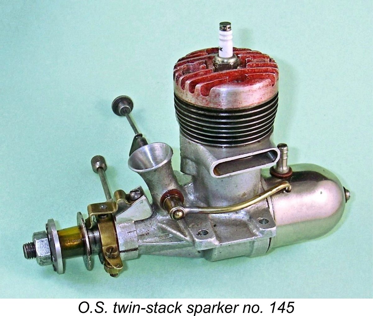
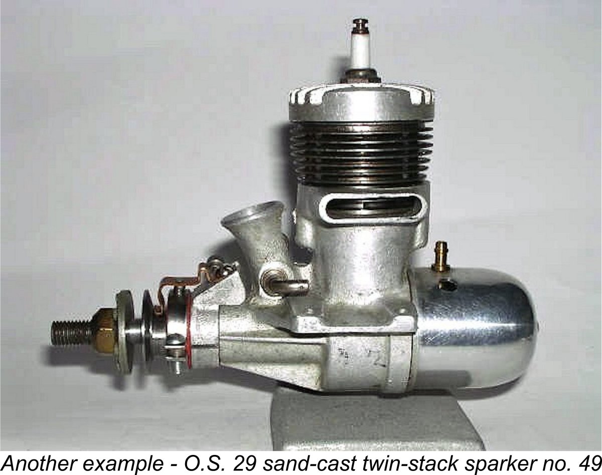 As stated earlier, there seems to be no documentary evidence whatsoever to clarify the genesis of the O.S. 29 twin stack sparker – even O.S. themselves appear to be in the dark. Nonetheless, the engine does undoubtedly exist, as witness the fine example in my own possession as well as several others known to reside in the hands of Japanese collectors. My example bears the serial number 145, and I have also had contact with the owner of illustrated engine number 49 of the same type. It thus appears certain that the serial numbering sequence started from 1 and that at least 145 examples were made.
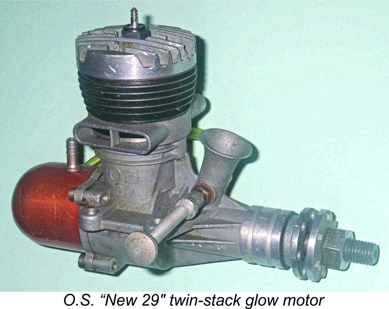
 The motor has the standard O.S. 29 twin-stack bore and stroke of 18.8 mm and 17.3 mm respectively for a displacement of 4.80 cc (.293 cu. in.). It weighs in at 9.25 ounces (259 gm) with tank and plug - pretty hefty, and that's without the necessary batteries and coil! Like all O.S. products then and later, the engine is extremely well-made, especially where it counts. All fits are beyond reproach.
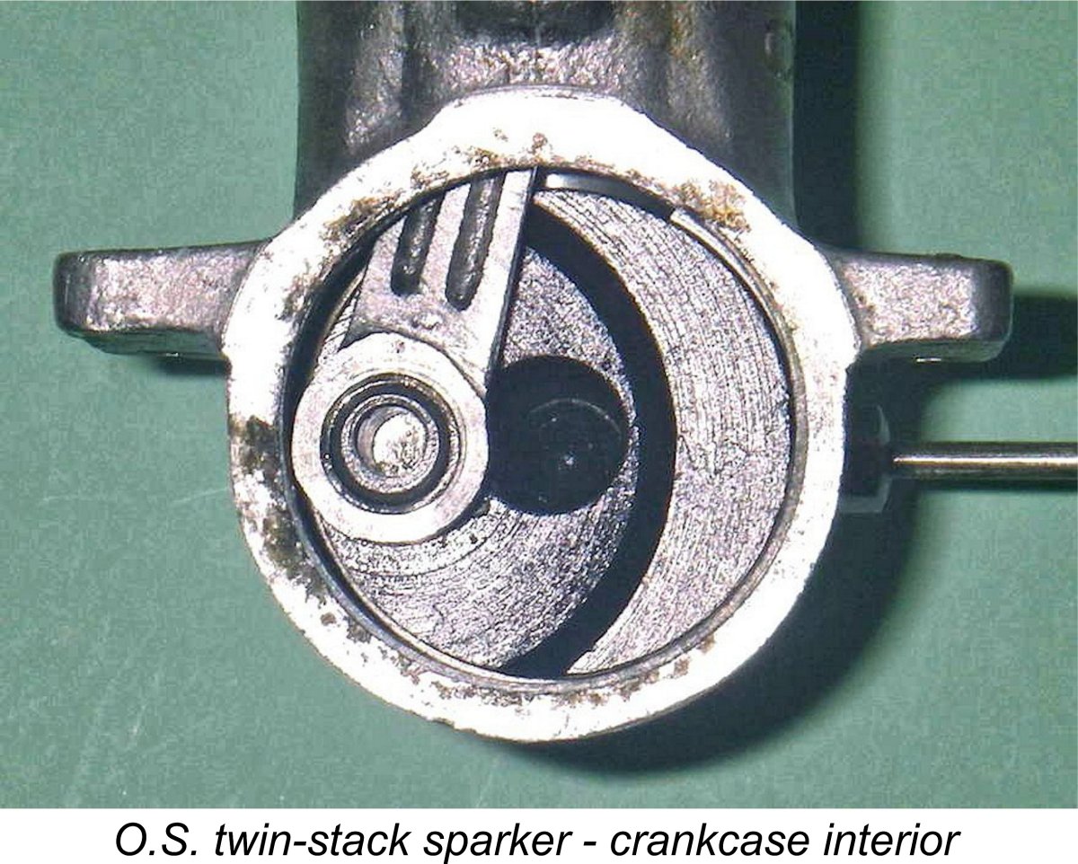 Although I normally don't dismantle any engine unnecessarily, especially one of this rarity, I felt that the search for knowledge left me no option in this case! So out came the tools, and soon all was revealed.
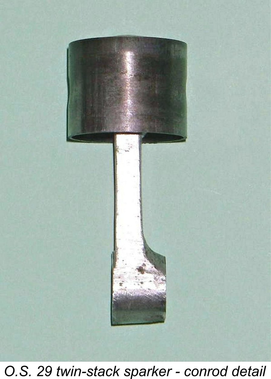 below the lower edge of the twin stacks. A seal is ensured through the use of a fairly thick non-metallic gasket. There are two pairs of exhaust ports, one pair on either side. Each pair feeds into one of the two stacks. The paired transfer ports are located directly below the exhaust ports, enforcing a relatively long blow-down period and a short transfer period. They are fed by two shallow bypass passages cast into the crankcase, one on each side. Unlike the later glow models, the steel cylinder and integral cooling fins of the sparker are left in their natural state rather than being blued.
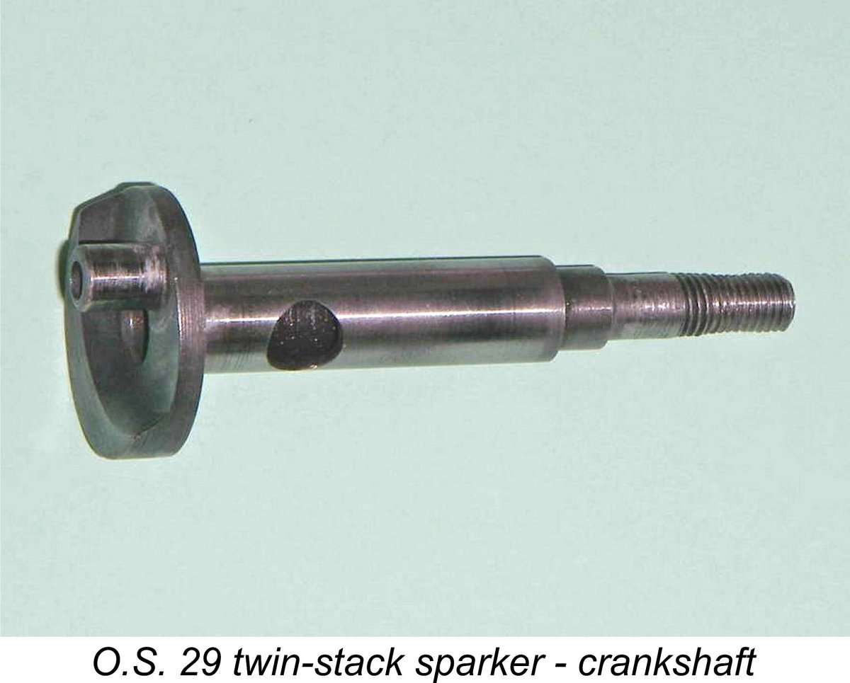
 This was an imposing task for someone who is not an expert on spark-ignition engines. To improve my odds of narrowing it down, I started with the first edition of the late Tim Dannels' invaluable "
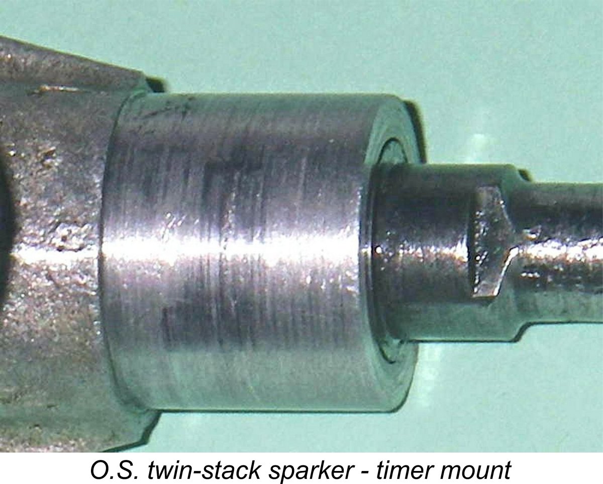 Some support for this notion may be found in certain measurements taken from the timer itself. Most significantly, it's mounted on a machined boss having a diameter of 0.625 in exactly - very Atwood-like indeed, with nothing metric about it! However, the threads used for the timer assembly screws are very odd indeed - they appear to be metric but are neither standard metric nor any standard US thread that I've ever encountered. As an example, the timer arm thread has an O/D of 0.090 in (2.30 mm) and a pitch of .55 mm (46.2 tpi) which is a case of close but no cigar to a 3-48 (.099 in. x 48 tpi). A 3-48 nut "rattles" on the timer arm and is a definite misfit - it would strip if tightened. I've never heard of a 2.3 mm x .55 metric thread - has anyone else??
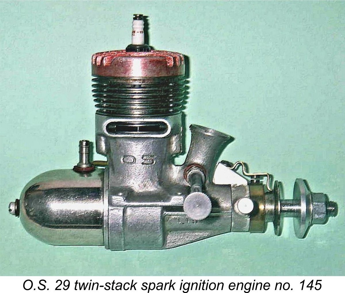 The possibility actually exists that Ogawa was not personally all that taken with this rather "un-Japanese" design but was in effect talked into giving it a try by Atwood, perhaps as the price of Atwood's co-operation on the marketing side. If this was the case, Ogawa may not have worried too much about whether or not the engine was a success - he had no immediate plans to produce it or promote it in any case.
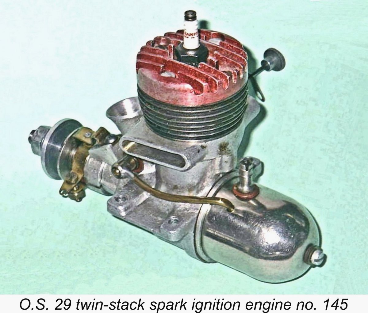 So the decision was taken to fit what amounted to left-over old-tech timers that Atwood already had lying about to what appears to have been no more than a short-run and un-promoted test series of engines. All that was required was to slightly alter the bend in the moving point spring.
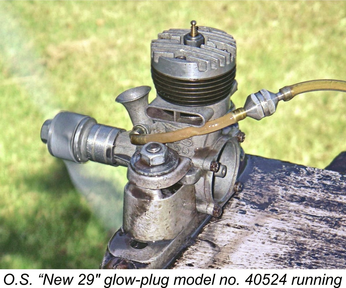 In the absence of any instruction leaflet, I obviously had no guidance available with respect to the appropriate airscrews to use for this test. I did however have a few prop/rpm figures measured some years previously for the die-cast O.S. "New 29" twin-stack glow-plug model which followed on the heels of the sand-cast sparker. Those figures were obtained using a methanol/castor fuel containing 10% nitromethane, so I wouldn’t expect the O.S. 29 sparkie to match them when running on low-grade gasoline. The glow-plug model delivered a peak output of around 0.400 BHP @ 12,000 rpm on that fuel. A 10x6 APC prop seemed to suit the engine well, turning at 10,100 rpm on the bench. It would speed up in the air to something approaching the peak.
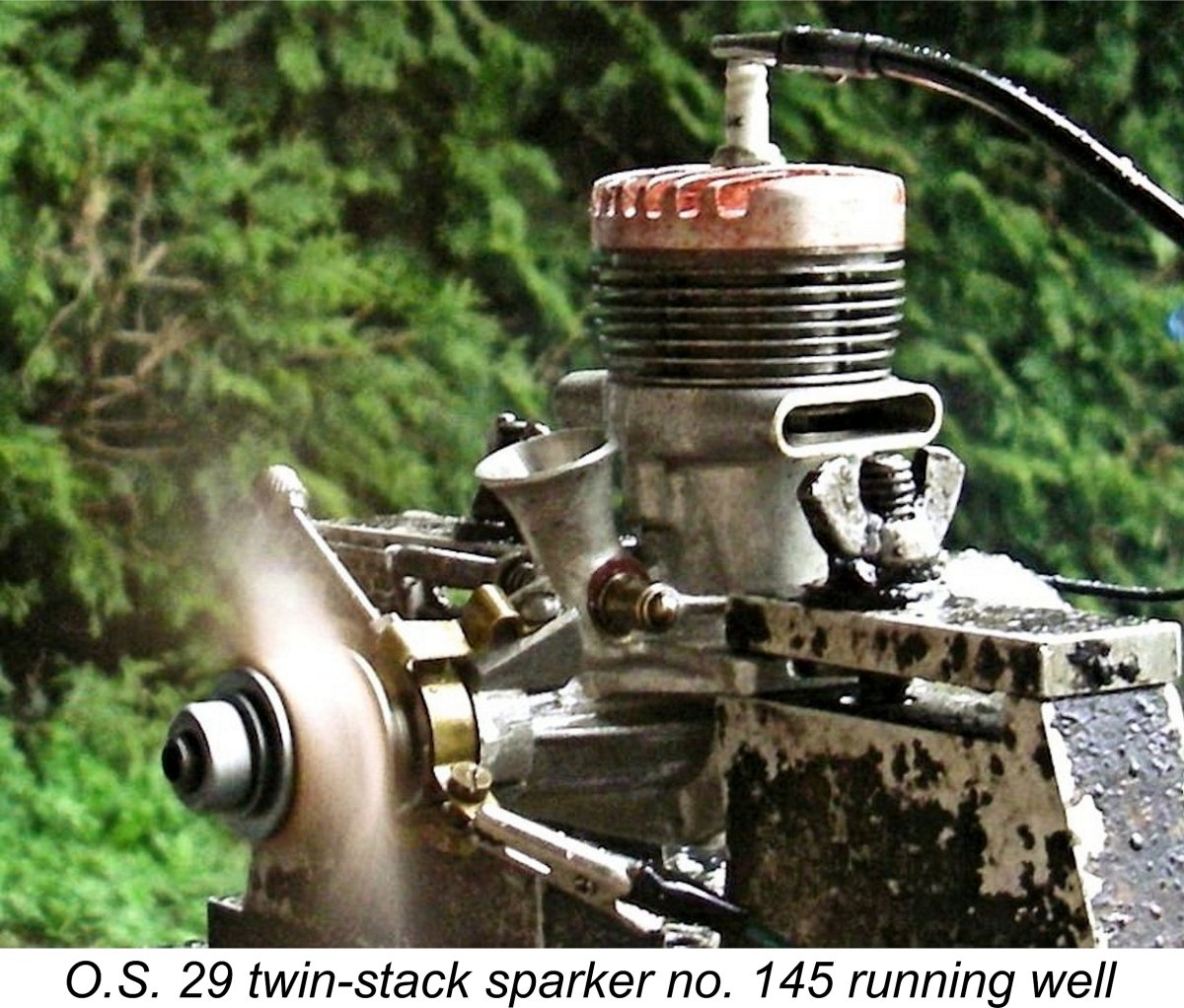 Now having a fair bit of experience running sparkies, I quickly found that this engine was somewhat different from most others that I’d tested in that it liked to be quite wet for starting – more like a glow-plug unit than a sparkie. When running a typical sparker, all that’s usually necessary is a few choked flicks prior to switching on the ignition, after which a start generally results immediately or nearly so. With the O.S., this procedure elicited no response at all. I found that it was necessary to administer a small exhaust port prime to get the engine firing. However, once it did fire it started up very quickly. I’d actually rate its starting qualities as excellent once the appropriate approach had been developed.
| |