
|
|
The Premier Lionheart 2.48 cc Faux Twin
In a separate article to be found elsewhere on this website I’ve recounted the story of the M.E.C. 1.2 cc diesel which put in a rather brief market appearance from March 1948 to mid-1949. That neat little ultra-lightweight side-port unit was marketed exclusively by the long-established firm of Premier Aeromodel Supplies Ltd. and the consortium of which it briefly formed a part, Model & Air Sports Ltd. The M.E.C. continued to be offered for sale by Premier Aeromodel Supplies up to July 1949. However, in late 1948 the Premier company had My companion article on the M.E.C. included some basic information about this fascinating design. That was all that I had until happy chance dropped a very nice example of the Mk. II Lionheart into my lap. The additional information which this fortuitous event provided was more than enough to make it clear that a focused article on the engine was well warranted. Now if you’re looking for “something completely different”, this is undoubtedly it! Quite apart from its unusual appearance, the engine displays a number of clever design features which have been pretty much ignored until now. High time to bring this highly distinctive creation out into the light of day! Background
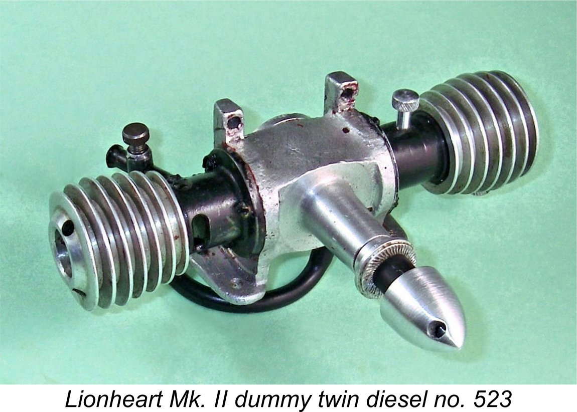
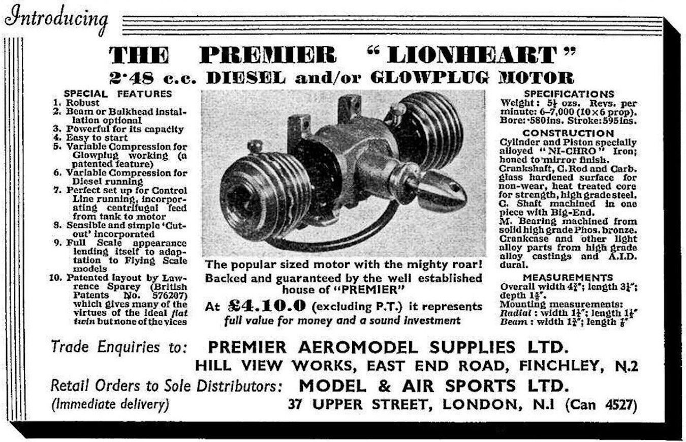
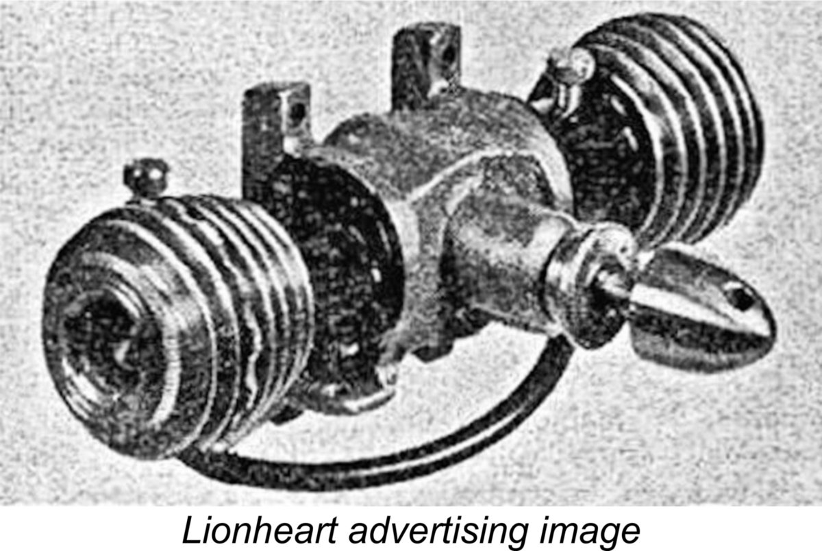
It appears that Sparey moved quite rapidly to arrange for limited production of his brainchild following the granting of his Patent, since Premier Aeromodel Supplies Ltd. published an announcement in their “Aeromodeller” advertisement of September 1946 stating that they would “shortly have available” The cited Patent is none other than that granted to Sparey on March 22nd, 1946 for his "dummy twin" arrangement! The advertisement stated that the proposed model would “be available in small numbers only to meet the requirements of the really discriminating modeller”. Clearly large-scale production was not envisioned - arrangements were evidently being pursued for an artisan level of manufacture. It’s evident that unforeseen circumstances delayed the introduction of this engine, since we hear no more of it until it put in a rather belated marketplace appearance in 1948, by which time its functional design had fallen rather behind the times. In the interim, the company’s attention had become diverted to the M.E.C. 1.2 cc side-port model mentioned earlier. That fine little engine made its commercial debut in around March 1948. As of December 1948, only the M.E.C. was featured in the company’s advertising - there was The engine that finally appeared as the Premier Lionheart 2.5 cc model made its advertising debut in Premier’s January 1949 placement in “Aeromodeller” magazine which is reproduced here at the right. Since the magazine appeared on the stands in the middle of the month prior to the cover date, considerations of editorial lead time clearly imply that the engine had actually materialized no later than November 1948. In keeping with its leonine name, the engine was promoted as “the popular sized motor with the mighty roar”! The Lionheart looked for all the world like an opposed-twin design. In reality, it was a single-cylinder unit - the second opposed "cylinder" was a dummy which actually served as the fuel tank in accordance with the Sparey patent. Oddly enough, the introductory advertisement failed completely to point this out - in fact, it elevated the level of confusion by stating that Sparey’s patented design provided “many of the virtues of the ideal flat twin but none of the vices”. The clear implication for anyone reading this advertisement while looking at the advertising image would have been that the Lionheart was a flat twin!
The Lionheart was very clearly intended to be mounted in a horizontal orientation with the working cylinder on the right (looking forward in the direction of flight). The express anticipated use of the engine was to power scale models, then very much in vogue. The recommended airscrew was a 10x6 - there was no specific recommendation for control line or free flight use, although the advertising did claim that the engine incorporated a "perfect set-up for Control Line running". Looking at the relative positions of the tank and carburettor, I beg leave to doubt this - the implications for centrifugally-induced fuel head variation during flight are pretty obvious! Claimed speed with the 10x6 prop was 5,500 RPM, although the Lionheart was said to be good for maximum speeds in the 6,000-7,000 RPM range. The engine could be either beam or radially mounted. In the latter case, the thrust line would be well above the surface of the bearers. Considering its relatively complex layout, the Lionheart's selling price of £4 10s 0d (£4.50) was by no means unreasonable. Even so, like its more conventional M.E.C. 1.2 cc predecessor, it appears to have sold in very small numbers. Consequently, surviving examples are in extremely short supply today. Upon close acquaintance, the Lionheart turned out to be a far more interesting engine than I had expected! Far from being a mere “novelty” or “gimmick”, it displays some very creative thinking! In fact, the “dummy twin” motif tends to draw attention away from much of its technical interest. Allow me to set the record straight! Description
The introductory advertisement for the engine (see above) provided a few structural details which are not readily apparent without dismantling. Both cylinder and piston were said to have been machined from nickel-chrome alloy steel, reflecting the similar material selection applied to the M.E.C. 1.2 cc model. The one-piece steel crankshaft ran in a phosphor-bronze bushing. A steel conrod was also featured. The crankcase was sand-cast in a high-grade casting alloy, while other light alloy components were machined from dural barstock.
It’s always been abundantly clear that an error must have crept in somewhere, since the published numbers are incompatible. Having acquired an actual example to check for myself, I was able to set the record straight. Careful (and repeated) measurements taken from my example yielded bore and stroke figures of 0.575 in. (14.605 mm) and 0.580 in. (14.732 mm) respectively for a displacement of 2.468 cc. I’m convinced that these are the One figure provided by the manufacturers that turned out to be more or less correct was the engine’s weight. The manufacturers claimed a weight of 5½ ounces for the Lionheart. My example weighs in at 5.7 ounces - near enough, and a commendably light weight for a 2.5 cc diesel, especially considering the inclusion of the rather bulky tank assembly. I attempted to remove the screw-in backplate, but couldn't shift it by "fair" means. Based on this initial experience, I’ve chosen not to dismantle my example all the way, since the intact 80 year old seals are clearly well and truly glued in place and would not survive dismantling. Moreover, since the engine has clearly done some running, the working parts are well “acquainted”, hence being best left undisturbed. However, the more interesting design features are readily apparent with only a minimal amount of dismantling.
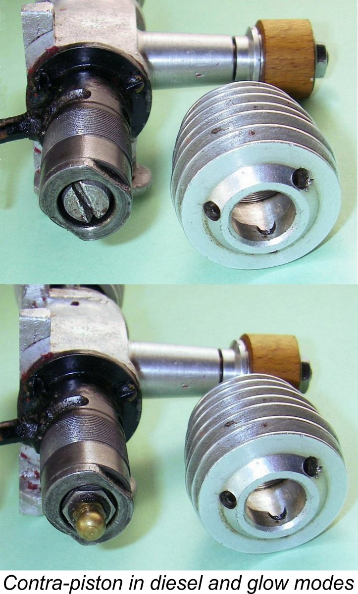
Early examples such as the one illustrated in the Premier advertising had a protruding “scalloped” cooling fin near the top to facilitate a secure grip. However, this was evidently found wanting, since most examples feature three holes radially The really interesting feature is the fact that the engine retains variable compression in both diesel and glow-plug modes! The previously-cited January 1949 introductory advertisement for the Lionheart specifically referred to the engine’s retention of variable compression when operated in glow-plug mode. This was claimed to be a “patented feature”, although the specific Patent was not cited. It’s possible that this referred to Patent no. 636,063 applied for by G. W. Rawlings on August 27th, 1948, which envisioned a similar variable compression diesel/glowplug concept, although it wasn't the primary focus of the Rawlings Patent.
The Lionheart’s flanged cast iron contra-piston is centrally tapped ¼-32. In diesel mode, that hole is plugged by a light alloy slot-head screw which seals on a normal copper glow plug washer. It only takes a minute to remove the screw and replace it with a glow-plug. The glow-plug is thus firmly secured in the contra-piston, the position of which remains fully adjustable. So the engine is indeed a variable compression glow-plug motor when operated with that form of ignition. You’d need to back off from the diesel setting when running on glow-plug! Note the flats on the top flange of the contra-piston. These are very necessary in order to permit the use of a spanner to prevent the contra-piston from turning in the bore as either the diesel screw or the glow-plug are fully tightened. The flange also sets an upper limit on the compression setting, thus minimizing the possibility of damage resulting from over-compression. All very well thought out! The dummy cylinder which serves as the tank is machined and blind-bored in one piece from aluminium alloy. The component thus incorporates the dummy cooling fins and the installation flange in unit. Note to owners with a propensity for "tinkering" - do NOT attempt to unscrew the dummy cooling jacket - it's in one piece with the rest of the tank! The likely result of such an attempt will be graunched fins on the tank. It's worth noting that the Lionheart could be operated with the tank removed. All that it would take is the removal of the three tank retaining screws which secure it to the crankcase. The engine would then become a conventional single-cylinder sideport diesel, albeit with a rather unique mounting configuration!
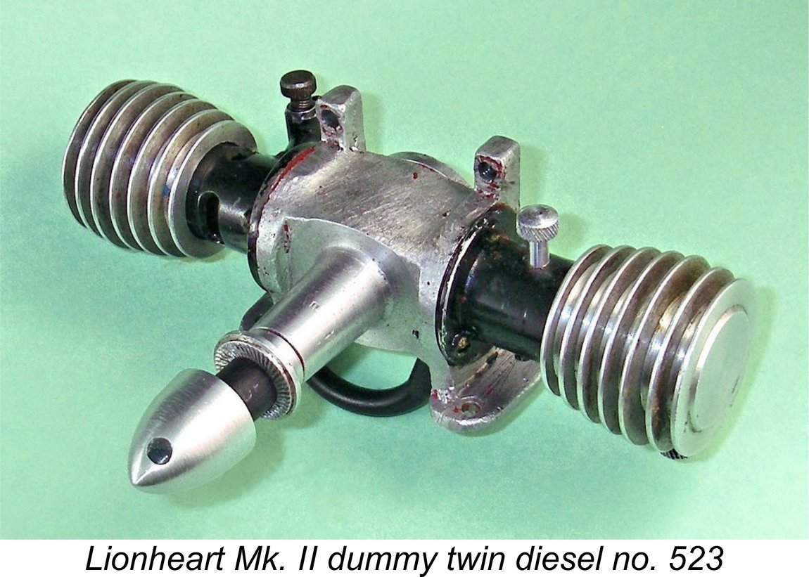
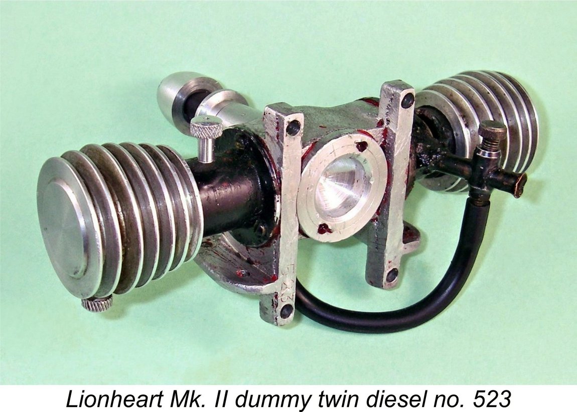
The engines have shown up with a variety of crankcase finishes. Examples have been seen which are painted in colours ranging from black through light and dark green to red! However, the red paint on my example as received was definitely not original - it had been applied rather carelessly and indiscriminately with the engine fully assembled, resulting in splotches of red appearing on various areas beyond the case where they had no business to be! The By contrast, a significant proportion of surviving examples have no paint finish at all. I removed the red paint on my example to return the case to its natural as-cast finish, which I suspect to have been the original appearance of this particular unit. In terms of the number manufactured, I can only say that the Mk. I version appears to be considerably less common than the Mk. II variant. A search of the literature along with inquiries among my contacts has so far confirmed the present-day survival of only three undoubtedly distinct Mk. I units, while I’ve been able to confirm the existence of only six distinct examples of the Mk. II version. There must be a few more out there, but this is indisputably a very rare engine. My example bears the number 523 neatly stamped onto the rear face of the left-hand radial mounting lug. This is presumably a serial number. In the absence of other reported serial numbers, I can’t confirm whether or not all examples were numbered, nor can I even hazard a guess as to the significance of this number. All that I can say with some certainty is that nowhere near 523 examples were made in total! Perhaps the sequence started at 500....?!? There are many precedents. The quality of the Lionheart's construction seems to be well up to the better standards of its era. All working fits are excellent - when turned over, the engine has a real "quality" feel, with nice snug bearings and perfect compression. But that's only half the battle! Next question - how does it run? Let’s find out! The Lionheart Roars Again! The example of the Mk. II Lionheart that I was fortunate enough to acquire appears to be little used, retaining both excellent compression and snug bearings. I planned to give it a run as soon as I could cobble up a suitable mount for it.
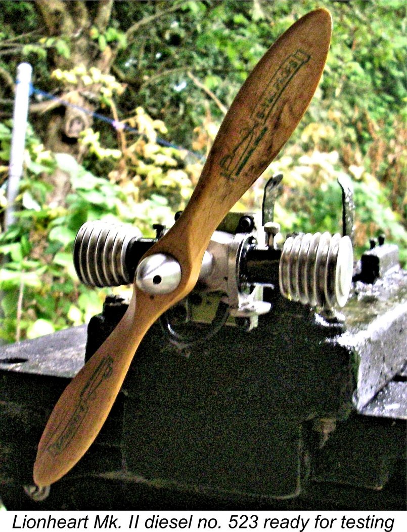
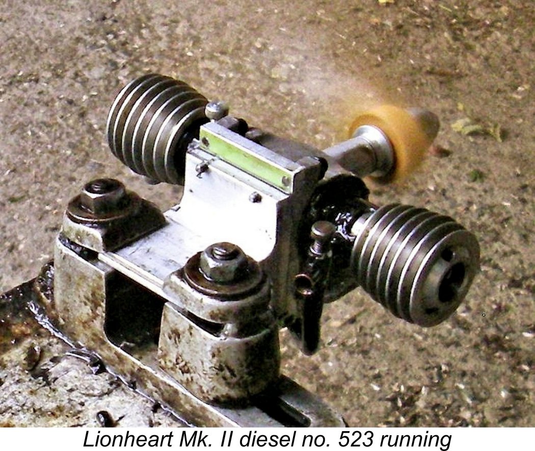
It took a little effort to create a test mount for this rather unusual engine. However, that task was eventually accomplished, and I was all set! My example seemed to have had some earlier running, evidently being all ready to go with no break-in required. The test mount that I had assembled placed the engine in what I believe to be its intended orientation - flat, with the power cylinder on the right-hand side (facing forward in the direction of flight). I elected to use the fuel pickup point at the base of the crankcase between the bearers. I believe that for most purposes this would be the preferred choice. With a 10x6 Top Flite Power Point wood prop fitted and a full tank of fuel, the engine was all ready to go. I opened the needle a few turns, applied a couple of choked turns, administered a small exhaust prime and got stuck in. The engine started firing immediately, but I had to increase compression somewhat to get it to keep running. In fact, I soon discovered that it was necessary to increase compression to the upper limit permitted by the contra-piston flange to get the engine running smoothly. This might be one slow-revving sideport diesel that would do better using a nitrated fuel with its lesser compression requirements. The compression adjustment system worked OK, although inserting the tommy bar into the most convenient of the three holes while the engine was running proved to be a bit challenging at times.
The Lionheart turned the 10x6 Top Flite Power Point wood prop at 5,200 rpm - a little below the manufacturer's claim, but the Top Flite PP is known to be a "slow" 10x6. The implied output at this speed was around 0.065 BHP. A switch to a "faster" APC 10x6 got the speed up to 5,700 rpm, supporting the manufacturer's claim, with an implied output of 0.069 BHP. Finally, I tried a BY&O 9x5, which was turned at 6,200 rpm for an implied output of around 0.064 BHP. The peak seems to be reached at around 5,900 rpm, at which speed the engine is developing some 0.070 BHP. It must be clear that this is a pretty lacklustre performance for a 2.5 cc diesel of 1949 vintage. Those big props move a lot of air, but not very fast! The engine would doubtless do OK in a free flight application such as a scale model, where its "mock twin" layout might well be quite attractive. However, its output is very much on the marginal side for control line use. All in all, it's pretty easy to see why the Lionheart failed to make any real impression upon the 1949 British model engine market. Summary and Conclusion
It's unclear whether or not the same manufacturer was involved with both the M.E.C. and the Lionheart, although it seems likely. A clue here may be the fact that the induction tube used on the Lionheart appears to be the exact same component fitted to the companion M.E.C. The use of black paint on the cylinder (and tank) of the Lionheart is also a feature which it shares with the M.E.C., as is the use of steel for the piston, cylinder and con-rod. The cylinder porting of the Mk. I version is also identical. The level of Lawrence Sparey’s direct involvement (if any) must remain a mystery. All that can be stated for certain is that the design of the engine was undoubtedly inspired by Sparey’s 1946 patent no. 576,207 - Premier Aeromodel Supplies Ltd. openly acknowledged as much. We’ll never know whether or not Sparey had any personal involvement in the engine’s production.
Interestingly enough, this final advertisement mentioned the Lionheart, stating that the Premier Grasshopper kit design was "ideal for the Premier Lionheart 2.49 cc "mock twin"". There was no mention at all of the companion M.E.C. The Hornsey Rise address likewise disappeared from the model scene and subsequently from the London address book when the area was re-developed. Perhaps the competition from nearby Ripmax (a former participant in the Model & Air Sports consortium) was too much to overcome. Still, before departing from the scene Premier had left us with a few examples of one of the more original model engines of the early post-war period. I hope that you’ve enjoyed the opportunity to learn a little about this very distinctive unit! ________________________________ Article © Adrian C. Duncan, Coquitlam, British Columbia, Canada First published April 2023 |
 And now for something completely different, as Monty Python’s
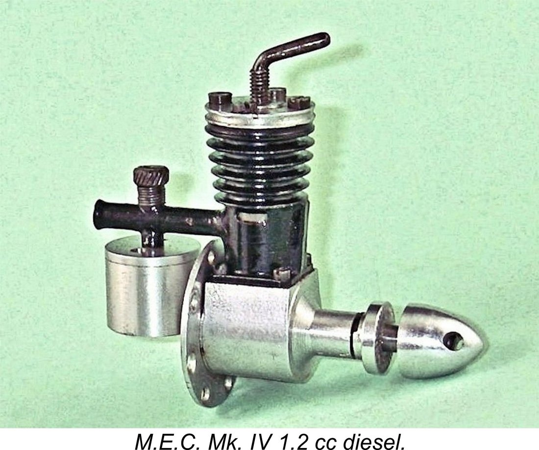
 At the time when I commenced my research into the Lionheart, the origins of its unique “dummy twin” arrangement remained obscure. However, my valued friend and colleague Gordon Beeby of Australia did some serious digging on my behalf which was very much appreciated. Quite apart from trolling his magazine collection for relevant advertisements, Gordon discovered that the engine was constructed in accordance with a British Patent which had been applied for on April 27
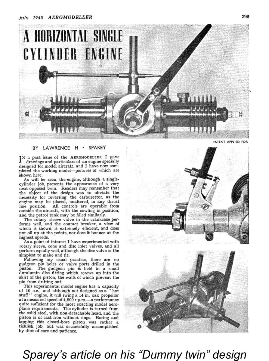 Sparey went on to present details and images of a completed spark ignition prototype in the magazine’s July 1945 issue. The Patent was finally granted on March 22
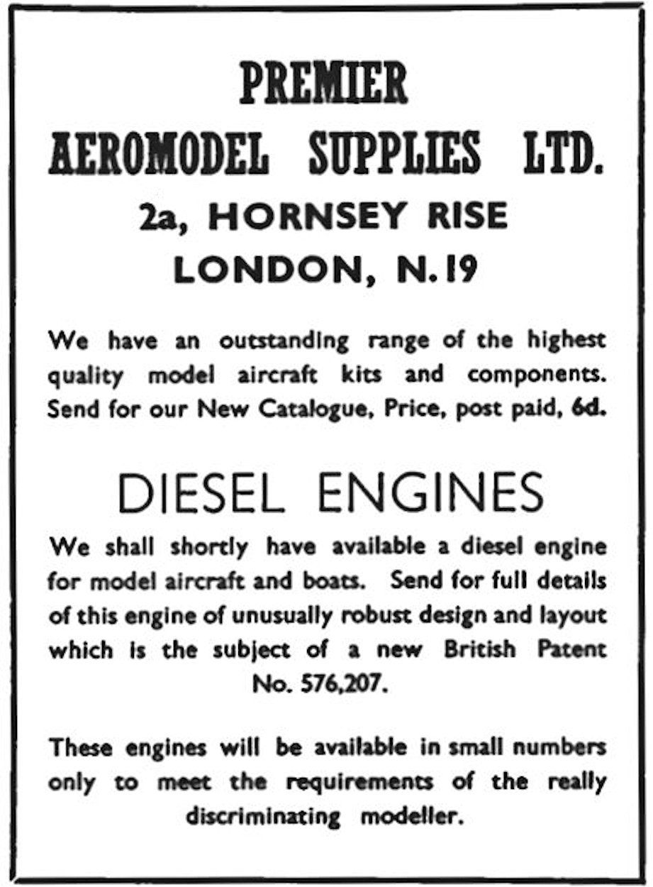
 as yet no mention of the Lionheart.
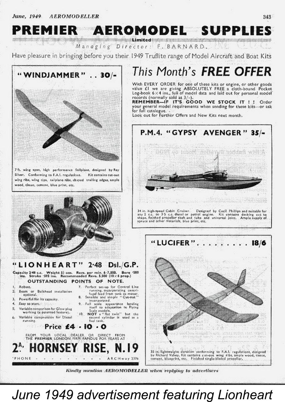 It seems almost certain that a number of aeromodellers ordered their own examples on the above assumption. We may well imagine that Premier enjoyed some heated exchanges with disappointed customers! In their later advertising the promoters were at some pains to set the record straight, stating categorically that the Lionheart was “NOT a "flat twin", but the second cylinder is used as a fuel tank”.
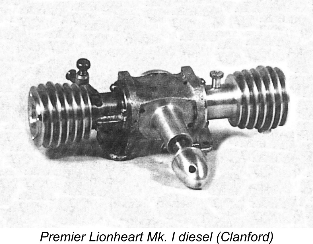 There were two distinct variants of the Lionheart. Both models featured side-port induction through a rather skinny soldered-on brass venturi tube at the rear. The working cylinder of the first model was arranged along
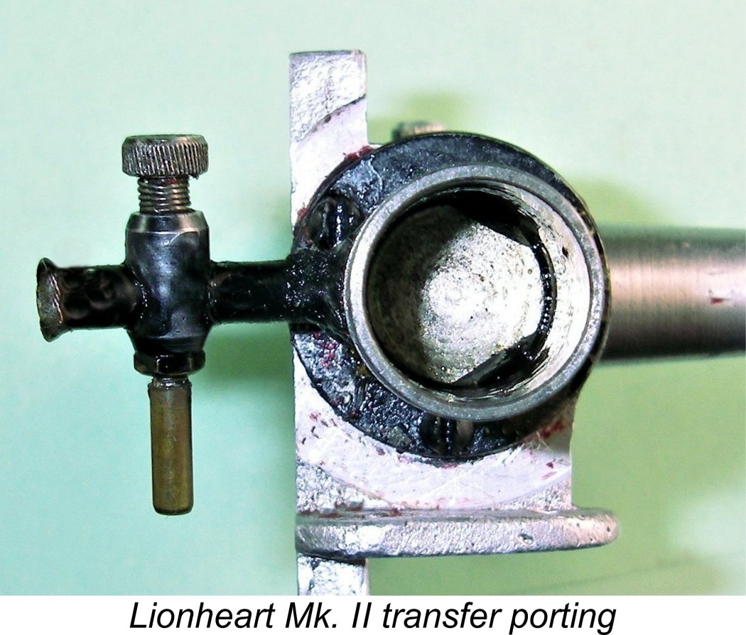
 The compression ratio of this engine is varied by rotating the screw-on cooling jacket a la
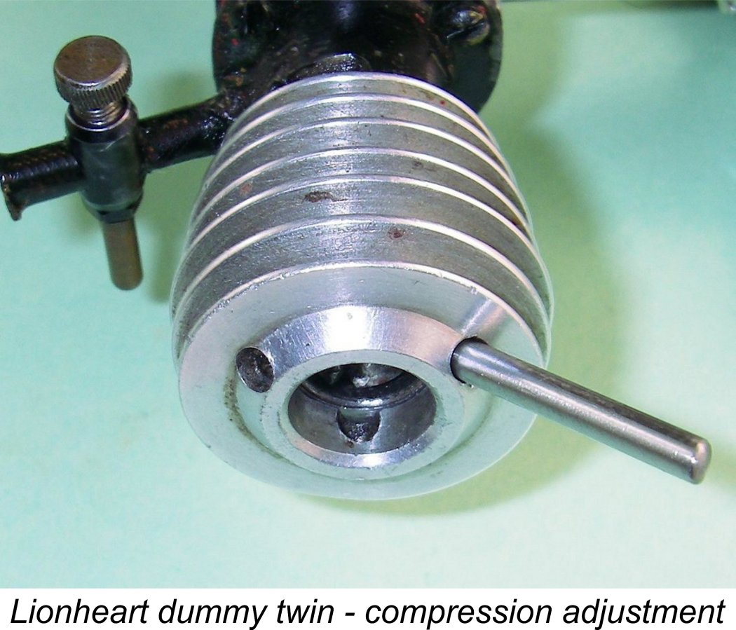
 The only parallel that I can think of is the
 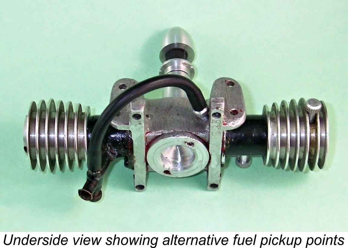 There are two alternative locations for the fuel supply nipple on the tank, both threaded 4BA. One is at the outer end of the tank and the other is below the crankcase between the bearers. Both are located at the bottom of the tank when the engine is mounted in a horizontal orientation with the power cylinder on the right (facing forward in the direction of flight). For most purposes the crankcase location would appear to be the most convenient. The supply hole not in use is plugged with an alloy screw similar to the one which closes the tank filler opening but with no air vent hole. The crankcase is sealed at the rear with a screw-in backplate.
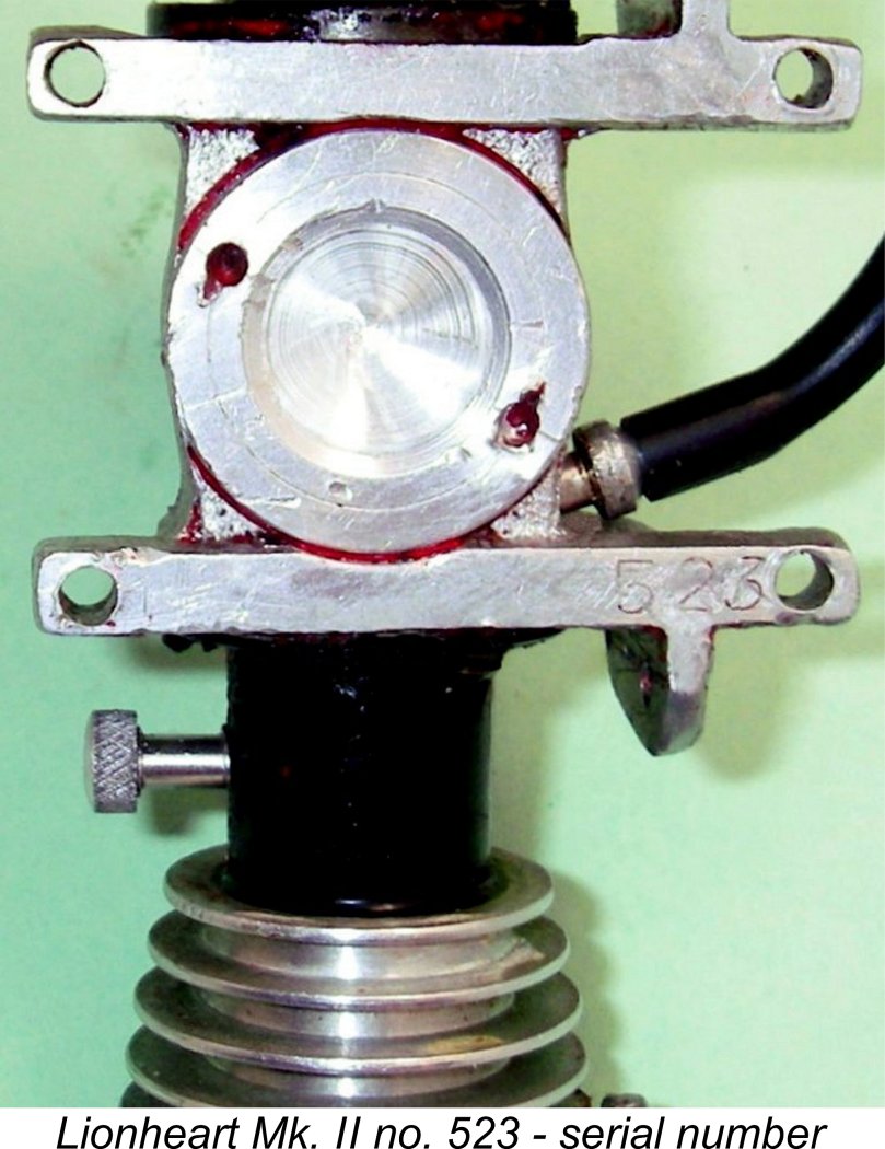
 The best procedure for starting proved to be to administer a single choked turn and a small exhaust prime. Using this approach, starting was quite straightforward. Excessive use of choking was to be avoided - it seemed to be quite easy to flood the crankcase. The needle valve setting proved to be a little ambiguous - the sweet spot was rather elusive, while there was a tendency to "hunt" unless the setting was perfect.
 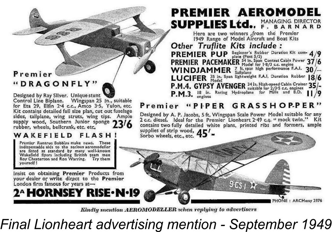 As with the M.E.C., the identity of the Lionheart’s manufacturer can no longer be determined. It seems quite clear that it wasn’t Premier themselves - the brochure supplied with the engine stated explicitly that the Lionheart was “manufactured for and on behalf of” Premier Aeromodel Supplies Ltd.
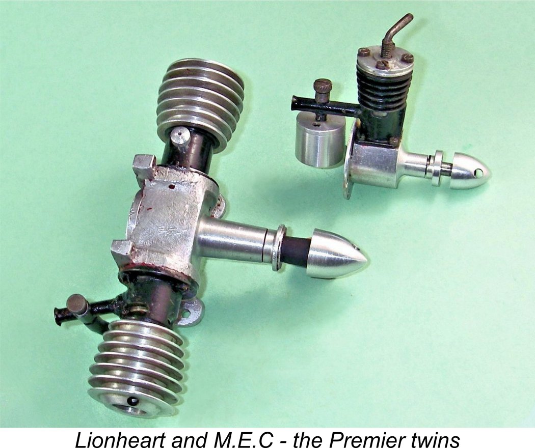 As far as I’m able to determine, the Lionheart represented the swan-song of Premier Aeromodel Supplies in the model engine business. In fact, the company itself was clearly experiencing difficulties as of the latter part of 1949, evidently ceasing trading at around that time, at least under the former name. The final Premier advertisement in “Aeromodeller” was their placement of September 1949 which is reproduced above.
 | |