
|
|
Stovepipe Success Story – the E.D. 2 cc Models by Adrian Duncan with Kevin Richards
I’d like to start right off by stating for the record that I couldn’t have got to first base with this discussion without the unstinting assistance of my friend, kindred spirit and colleague Kevin Richards. As the world’s leading authority upon all matters relating to E.D., Kevin’s involvement is indispensable in the writing of any authoritative article about any aspect of the E.D. story. Thanks, mate!! Kevin has been working for some years now on a book about the E.D. range. I have no doubt that this book will represent the last word on the E.D. range and will reveal far more detail than space or knowledge allow me to present here. All that I will attempt is a summary of what I consider to be the main points of interest. The devil’s in the details, and I‘ll leave most of those to Kevin. I’ll be among his first customers! As with many products of the E.D. company, the history of the 2 cc sideport models is by no means straightforward, and there are numerous minor variants across which we’ll stumble along the way. It’s not easy disentangling all of this, but I’m prepared to have a go!! Kevin’s book will doubtless reveal all when it finally appears, so this article should be viewed as merely an interim summary. The E.D. 2 cc sideport model was the very first product of E.D.’s model engine division following the company’s establishment in 1946. It’s clear that E.D. were very much feeling their way at this time, and the early history of their 2 cc diesel line strongly reflects this situation. It is this factor as much as anything else which makes the story of these engines an extremely complex one even by E.D. standards! Pending the release of Kevin’s book, a summary of the full story of the E.D. enterprise may be found in a separate article on this website.
In addition, a comparative study of the engines' performances to identify limiting factors and measure the effect of their remediation tells us a great deal about the functional design of these units. As you'll learn, these limitations were readily identifiable and very easily rectified, with extremely positive results. It will always be a matter for wonder that E.D. never identified and dealt with some of these issues themselves, as they could have done very easily. Quite apart from that, over the years Kevin and I have both encountered many of these units which have been assembled from a collection of spare parts or by combining components from multiple incomplete examples. I confess to having a few such units myself! In many cases, engines which are restored in this way are made up of components which are incompatible with the serial number which appears on the crankcase. As model engine historians and collectors, Kevin and I both feel that it’s in everyone’s best interests that engines which are restored in this perfectly legitimate manner are as representative as possible of the form in which they were originally sold. At the very least, any departures from the original configuration need to be recognized. We hope that our work may help other collectors to accomplish this goal with their own restorations or when considering further purchases. A major key to getting to the bottom of this story is provided by the highly informative E.D. serial numbering system. This system allows us to identify and date specific examples of E.D. engines very closely. Without this capability, establishing the sequence of variations on the basic theme would become almost impossible. It’s therefore important at the outset that readers fully understand this numbering system. Those having a broader interest in the E.D. range in general may wish to review the full explanation of the system to be found elsewhere on this web site, if they have not already done so. All that I’ll attempt here is an explanation of the system as applied to the 2 cc models. The E.D. serial numbering system
However, neither the original E.D. 2 cc model nor the subsequent Mk. II were ever assigned a letter or number to designate those particular designs. Accordingly, serial numbers of these engines (with the exception of the original E.D. 2 cc model to be described below) begin with a batch letter broadly indicating the month of production. The months are lettered alphabetically, A being January, etc, with I being omitted to avoid confusion with the number 1 and L also being omitted, perhaps to avoid it being mistaken for an inverted-struck 7. N thus indicates the December batch, which was always the largest in any given year, presumably to deal with the Christmas rush. This batch letter was followed by a batch number indicating the position of that particular engine within the indicated month’s batch. A / symbol was used in many (but not all) cases to separate the batch letter from the following batch number, as in the above example. The sequence was completed by a number (or in some cases two numbers or a further letter) to indicate the year of manufacture. This was usually (but So for example, engine number B 23/7 was an E.D. Mk. II made in February 1947 as the twenty-third engine to have been produced in that month’s batch. Crankcase number J 1252/7 illustrated at the right was originally fitted to the 1252nd Mk. II made in September 1947. When the hotted-up Comp Special version of the E.D. 2 cc model was introduced in December 1947, it retained this system, the sole difference being that a model identification letter C was added at the end of the serial number sequence. This placement was presumably to prevent it from being confused with the C batch letter for March which appeared at the start of the number sequence. An example of such a number is C 57/8C, which denotes an E.D. Comp Special made in March 1948 as the 57th engine in that month’s batch. The serial numbers are thus quite definitive in designating the type of engine, the year and month of manufacture and the position of the engine within the batch produced in that month. Moreover, the batch numbers provide us with some basis for estimating the total production of engines during the month in question. As a model engine historian, I truly wish that other companies had adopted a similarly descriptive numbering system! A pre-requisite to gaining an insight into the sequence of variants based on the serial number system is access to a sufficient data-base of engines and associated serial numbers. Between us, Kevin Richards and I had direct access to some 34 examples of the Mk. II and 29 examples of the Comp Special during the writing of this article. All of these examples had excellent provenance regarding the originality (or otherwise) of their condition. The resulting database is sufficiently large that we're able to trace the chronological development of these engines with some confidence. Particular thanks must go to Kevin for generously sharing the data embodied in his outstanding and very comprehensive collection of E.D. engines of all types. With those preliminaries taken care of, we’re now ready to embark on our journey ……… The Story Begins .......
Although operated independently, Nash & Thompson was an element of the Parnall Aircraft Company of Yate, Gloucestershire. They were located on Oakcroft Road, Tolworth, Kingston upon Thames. The full story of the E.D. company’s establishment and ongoing history may be found in a separate article on this website. For the first nine years of its existence the company was located at 18 Villiers Road in Kingston upon Thames, Surrey. These premises were located immediately adjacent to the very large Vine Products (VP) wine bottling and distribution plant. In the accompanying rather fuzzy air photo, the E.D. factory is the white gable-roofed recangular building with the multiple skylights. The VP offices are in the rather elegant building to the right. What appears to be E.D.'s Ford delivery van is parked in the forecourt of the E.D. premises. The E.D. factory was re-developed from a converted commercial-scale Sanitary Laundry which had occupied the site prior to WW2. According to later reports, the floor area of these premises was around 4,500 square feet. My sincere thanks to Mike Noakes for providing this information along with the attached 1952 air photo of the E.D factory. The location has been comprehensively redeveloped today for residential purposes.
The name of Basil Miles has frequently been associated with the design of the E.D. engines. Indeed, Alan Greenfield believed that Miles was instrumental in convincing E.D. management to enter the model engine field in the first place. However, the E.D. 2 cc models under discussion here bear absolutely no imprint of Miles' design style. In fact, the first E.D. product with which Miles’ name was openly associated by the company was the 2.46 cc E.D. Mk. III Racer introduced in March 1951, although it does appear likely that he had at least an advisory role in the 1949 design of the 3.46 cc E.D. Mk. IV, with which he is pictured in the attached illustration. The record shows that he never held an official position within the company at any time, acting throughout in a consultative capacity. Nor was he one of the original shareholders in the company. The idea that Basil Miles was not centrally involved at the outset is strongly supported by the observation that the design of the early E.D. engines represented a significant step backwards from the far more If we can believe the later evidence of Jack Ballard, the founding Managing Director of the E.D. venture, the early E.D. engines were designed by a fellow named Charlie Cray. This claim is somewhat clouded by the fact that only one of the surviving design drawings of the early E.D. engines bears Cray's signature. Even so, the fact that Basil Miles and Charlie Cray were fellow members of the Malden model hydroplane racing club is certainly consistent with both of them having some level of involvement or at least influence at E.D. The connection would doubtless have facilitated Miles' input to further engine developments at E.D., ultimately leading to his central role in the design of later models. Regardless of responsibility, the development of a new line of model engines naturally takes time. However, that was a commodity which the model engine division of the newly-established company did not have in abundance – if they were to justify their existence, they had to get some saleable products out into the marketplace pronto, both to keep the engine-making workforce employed and also make a worthwhile and much-needed contribution to the company’s revenues. As a result of this, the original E.D. 2 cc model first appeared in a very under-developed state. E.D.’s First Engine - the E.D. 2 cc Model Although the original E.D. 2 cc model was apparently never advertised, there are references in the contemporary modelling media to examples having appeared on flying fields in the south of England by December 1946. The absence of any advertising fanfare suggests that the appearance of this model at the time in question was more in the nature of a testing of the waters than a serious attempt to move straightaway into the model engine market. In fact, Kevin Richards believed that this model was never actually offered for public sale and that the examples seen in action in late 1946 were predominantly test units in the hands of E.D. employees or associates. This may be true, but it does appear possible that a fair number of these engines may have been made over a two or three month period. Kevin reported the existence of an engine which is almost certainly an example of this early and now extremely rare model. It bears the serial number 407/7, which is inconsistent with E.D.’s later serial numbering system in that it does not have a monthly batch indicator. The engine does not display the E.D. name or the model type anywhere, but is otherwise identical to the introductory Type 1 version of the E.D. Mk. II to be described below with the exception of the prop driver assembly. Based upon the final digit, this example appears to date from early 1947. At first glance, the number would appear to imply that the engines were sequentially numbered without reference to their month of production and that at least 407 examples of this type were made in total during the period late 1946 to early 1947. This is certainly possible, although it’s extremely difficult to reconcile with the fact that there is only one presently-known survivor........ we’ll probably never have a satisfactory explanation for this figure. The E.D. 2 cc model seems to have been released prior to E.D. finalizing their broader development plans on the model engine side, once again implying a somewhat premature release which was driven by the need to keep the workforce busy and generate some quick cash flow. The sand-castings used in its construction were considerably rougher than those which came later. However, it would seem that the initial flying field reaction to the unheralded new model must have been sufficiently encouraging that the company decided shortly thereafter to develop the engine further as a commercial offering and to progress to the eventual development of a range of model engines of different displacements. Series production of the re-designed and re-designated model, the soon-to-be famous E.D. Mk. II "Penny-slot" diesel of 2 cc displacement, appears to have commenced in February 1947, again with little initial fanfare. It was not until March of 1947 that the company began to advertise this model, which they continued to do most energetically from then on. The E.D. “Mark” Model Identification System
The Mk. I Bee was assigned the model identification number 1. The illustrated example of the Bee bears the serial number 1J 163/8, making it an early example from September 1948. At first sight these facts might be taken to imply that the company’s first advertised offering was designated as their Mk. II because the decision had already been taken to develop a 1 cc engine which was to be designated as the E.D. Mk. I. In this scenario, the Mk. II was released as soon as possible in order to generate some doubtless-needed cash flow, leaving the Mk. I designation available for the future 1 cc design whenever it was ready. As matters turned out, even the Mk. III beat the Mk. I into the field, as noted earlier. The end result was that the “Mark” numbers of E.D.'s engine range increased with displacement rather than with the order in which the designs were released. On the surface this looks reasonable enough, although it does imply a considerable degree of foresight and advance planning on E.D.’s part going back to early 1947. However, Kevin Richards has presented a persuasive argument to the effect that matters were almost certainly more convoluted than this! It’s actually more probable that the decision to re-designate the original 2 cc model as the Mk. II was nothing more than a marketing ploy to convince the public that considerable development of the original 2 cc model had already taken place. Kevin’s view of the matter is strongly reinforced by his possession of irrefutable evidence in the form of a boxed example that the Comp Special of December 1947 (see below) was originally intended to be known as the Mk. III 2 cc model!! The label on the box clearly shows both the model designation as Mk. III and the displacement as 2.00 cc. This makes it clear that as of late 1947 the original plan was to designate the Comp Special as the 2 cc Mk. III model. This in turn clearly implies the prior existence of Mk. I and Mk. II versions of the same 2 cc model. The original E.D. 2 cc model was evidently seen at the time as the E.D. Mk. I. If this scenario is correct, as seems highly likely to me, then the fact that there was a gap in the “Mark” sequence to accommodate the far later Bee was entirely fortuitous. Since it certainly doesn’t take 18 months for a large and well-equipped company to develop a simple engine like the Bee from scratch, it It was seemingly at that stage (after development of the Bee had commenced and a few Comp Specials had been manufactured and packaged as Mk. III’s) that someone at E.D. belatedly noted the fortuitous gap which had been left in the Mark sequence for their new 1 cc model and realized the neatness of going up the displacement categories in step with the Mark numbers. Having come to this realization, they quickly removed the Mk. III designation from the Comp Special, thus leaving that designation free to be applied to the forthcoming Mk. III 2.49 cc model, of which much more elsewhere. The fact that the improved 2 cc engine of December 1947 was never advertised as anything other than the Competition Special suggests that the boxed Mk. III 2 cc models were part of the stock build-up run which always preceded the announcement of any new engine for which brisk sales were anticipated. E.D.’s Design Philosophy and its Consequences It is readily possible to draw some pretty clear conclusions regarding E.D.’s thinking at this point, and this is a most constructive exercise since a good deal of what was to follow was influenced by the decisions taken at this formative stage of the company’s activities. Given the pressing need for the engine division of the new company to activate its workforce and establish a viable cash flow as quickly as possible, several key imperatives must have presented themselves to E.D. management. Firstly, the company’s initial engine offering would clearly need to possess the virtue of simplicity of construction. This would translate directly into a shorter development period as well as a lower manufacturing cost and consequently a lower selling price and/or a higher potential profit margin. It would Secondly, and equally importantly, the engine would have to perform at a level which was fully on par with other competing models in the same general displacement category. At the time in question (late 1946 - early 1947), domestic competition in that category was relatively thin on the ground - only the Mills 1.3 Mk. I Series I was reaching the market in commercial numbers, although there were quite a few small-scale manufacturers emerging at the time, including Majesco with their 2.2 cc model and Dyne with a 2 cc design of their own. Although relatively few in number at the time, these models represented real competition for E.D.’s new product. Time was to demonstrate that the basic design of the E.D. Mk. II fulfilled the above conditions very well indeed. Certainly, once it was fully developed the design proved itself to be so sound that despite a number of detail modifications as the years went by, the Mk. II and its derivatives remained essentially unchanged throughout the entire remaining 13-year production life of the E.D. 2 cc engines. The claim regarding the engine’s basic simplicity might be argued given the number of individual components involved, especially However, there was a third imperative - the company needed to get their own engine design onto the market relatively quickly in order not to give too much of a head start to the Mills competition which had appeared earlier and the FROG 100 diesel which had already reached the prototype stage. It would appear that the company met this need by skimping the testing phase of the engine’s development, relying upon the inherent simplicity of the design to keep them out of trouble. It should then come as no surprise to note that in their original form the E.D. 2 cc and Mk. II models displayed a number of glaring developmental shortcomings. As we shall see, the resulting necessity for E.D. to deal with those shortcomings as they became apparent seems to have consumed much of their engine development program during 1947, with a consequent delay in the development of other models which would have diversified their product line and hence broadened their market base. It would seem in hindsight that E.D. may have paid rather dearly for the possibly premature release of their first model in terms of a significant delay in the highly desirable diversification of their range. We already saw that their Mk. I model, the 1 cc Bee, was not destined to appear on the market until mid 1948, some 18 months after the initial appearance of the first 2 cc models and a full year after the debut of the FROG 100! It’s certainly true that the delay in the release of the Bee might well have been a result of then-prevailing market conditions. As of early 1947 a 1 cc engine would have been viewed in Britain as a sub-miniature, and the British market quite likely wasn’t yet fully receptive to engines of that size. It took the advent of the Kemp, FROG, AMCO .87 and Mills .75 engines to overcome that impression. E.D. Mk. II - General Design Features Viewing things objectively, it must be said that the basic design of the original E.D. 2 cc model and the more-or-less identical Type 1 version of the Mk. II (see below) displayed little in the way of truly original thinking. The engine was an essentially orthodox long-stroke side-port diesel of its era, with a bore of 0.500 in. and a stroke of 0.625 in. for a displacement of 2.00 cc exactly. These bore and stroke dimensions remained unchanged throughout the entire 13 year production life of the original Mk. II and its various 2 cc derivatives. The cylinder was a very simple affair consisting of a steel tube which had an integral square-section flange near its base to afford a secure means of mounting the cylinder on the top of the crankcase using four 6 BA screws. The upper part of the cylinder was threaded externally for the separate screw-on aluminium The bypass passage was worthy of note - it was a simple channel-section brass stamping which was soft-soldered onto the front of the cylinder to connect two rectangular ports cut through the front of the cylinder wall. Gas entered the lower bypass from the crankcase through a rectangular port cut through the front of the piston skirt. At bottom dead centre this piston port registered with the lower of the two transfer ports cut through the cylinder wall. Gas entered the bypass through the piston port and the aligned lower transfer port and was discharged into the cylinder through the upper port after passing upward through the bypass passage which joined the two cylinder ports. The soldered-on bypass channels used on the early models were of a rather narrow and hence somewhat constrictive size. The upper transfer port was constrained to a width of only 0.186 in. by the narrow dimensions of the associated bypass passage.
Since the exhaust ports were relatively shallow in terms of depth, neither the original E.D. 2 cc model nor its successor Mk. II featured sub-piston induction. The example whose exhaust port is shown in the accompanying image at the right clearly once had stacks which are now lost. The flat-topped piston was of cast iron and was quite a heavy piece of work. This was of little consequence given the design speed range of the engine – in the vicinity of 7,000 rpm at the most. Even so, the crank-web of the one-piece hardened steel crankshaft was quite generously counterbalanced to offset the vibratory effects of the heavy piston and long stroke. Early pistons had no step cut into their crowns at the transfer location - that modification came later, as we shall see below. Like the crankshaft, the con rod was of hardened steel – normally a problematic material for diesels due to its tendency to produce “waisting” (or centralized wear) on the gudgeon pin. However, long operating experience shows that the E.D. 2 cc units do not display this problem to an unusual degree, indicating that the narrow bore coupled with the low operating speeds and associated lower compression settings reduced the loadings to the point where excessive wear was not that much of an issue. The rods used in the early models had a square section, which was later changed to the more familiar round section. The main design issue with the conrod/crankshaft assembly was the very short length of the crankpin. Although this pin was extremely resistant to flexure, there was no restraint to the big end's ability to move rearwards on the pin, allowing the rod to tilt during operation to the point where rubbing contact with the backplate could develop over time. My good mate Maris Dislers has given a good deal of thought to the implications of this issue. His highly pertinent observations will be fully discussed in a later section of this article. The crankcase and front bearing housing were originally both sand-cast in aluminium alloy. The front housing was secured to the crankcase with four 6 BA screws. This housing incorporated a main bearing consisting of a two-piece cast-iron bushing, which in combination with the hardened steel crankshaft guaranteed both low friction and an almost infinite working life. The sand-castings used on the original E.D. 2 cc models were rather rough – by the time the Mk. II version was released by that name, E.D. had significantly improved the quality of these castings.
The 3/8 in. diameter prop mounting boss at the front of this element of the system was milled away for half its diameter. The other half of the boss was formed by a similar partially-milled protrusion formed at the rear of the front element of the system, which incorporated a peripheral V-section groove for cord starting. When the two pieces were combined, the two half-bosses dovetailed to form a complete 3/8 in. diameter boss. The result was in effect a bobbin-type prop mount having a split prop boss of 3/8 in. diameter and of variable length (thanks to the split) to accommodate different prop hub thicknesses. The interlocking of the front and rear elements constrained both parts to turn as a unit with the shaft, and hence the prop was actually driven by both the rear and forward elements of this set-up, minimizing the chance of the prop slipping on the plain faces but also retaining some capacity for slippage to occur in a hard crash, thus hopefully protecting the shaft against breakage. The front element of the prop driver incorporated the previously-mentioned peripheral groove, presumably to facilitate cord starting, which at that time was still in use by some modelers. The two-piece prop driver unit was held in place along with the prop by a large solid alloy spinner nut of hexagonal form to facilitate the use of a spanner for tightening. A heavy and complex but very effective means of prop attachment, the one criticism being that the available thread length was only sufficient for the mounting of props with relatively thin hubs. This basic set-up was to last essentially unchanged for the entire production life of the Mk. II. The finishing touch was a neat sand-cast aluminium alloy intake venturi with integral fuel pick-up tube and needle valve mounting. This was mounted on an internally-threaded inlet boss which was soft-soldered to the rear of the cylinder at the induction port location. A nicely-made aluminium fuel tank of more than ample capacity threaded directly onto the bottom of the fuel pick-up tube. This tank gave a run of well over three minutes. It too remained a feature of the Mk. II for almost its entire production life. The needle valve was of the surface-jet type, with the fuel jet consisting of a simple hole in one side of the venturi passage. The tapered needle crossed the passage from the opposite side to engage with the jet. This resulted in minimal obstruction of the venturi section by the needle valve assembly, at some cost in terms of suction. A fuel cut-out was also incorporated, consisting of a brass arm which controlled an air-bleed into the fuel line just prior to the jet. This worked very effectively. One slightly unusual feature to which reference has already been made was the use of soft solder to attach the bypass passage, the exhaust stacks (where fitted) and the carburettor boss to the steel cylinder. This was no problem in the case of the carburettor boss and bypass passage, since these were directly cooled by the low-temperature incoming fresh mixture when the engine was running. However, in the case of the exhaust stacks which were often fitted to the Mk. II, this method of attachment could be problematic. Especially during warm-weather bench running where after-run air cooling on the glide was not available, the cylinder temperature in the vicinity of the soldered joint around the exhaust ports could become high enough through conduction at the end of a run to affect the integrity of the joint, sometimes to the point that the stacks simply fell off or were easily knocked off! The loss of the stacks naturally had no effect upon the running qualities of the engine, the consequence being that when this happened they were frequently not replaced. This explains the significant number of Mk. II engines which are missing their stacks today. An example was illustrated earlier. Once a number of bugs had been worked out, the resulting engine in its finalized form proved to be both rugged and adequately powerful by the standards of the period. Nor was the all-up weight of a shade over 6 ounces (171 gm) by any means out of line by contemporary standards. Although a number of design details were amended as time went by (details to follow), the basic design was to prove to be among the longer-running success stories in British model engine production history. E.D. Mk. II - Compression Adjustment
The E.D. company was clearly in the ever-growing camp that believed in the virtues of giving the operator the ability to adjust the compression ratio of a model diesel engine in the field. But they seem to have been less convinced of the need to make such adjustments simple and convenient, especially while the engine was To adjust the compression, one simply screwed the cooling jacket further down or unscrewed it to the required extent. The contra-piston followed these adjustments faithfully. A spigot was machined onto the top of the cooling jacket with a slot milled This process was far less convenient than a conventional comp screw would have been for making adjustments, particularly while the engine was running – getting the penny into the slot of a vibrating engine was in itself a challenge at times, and the slot tended to become marred quite quickly. It appears likely that E.D. were thinking along the lines that once a good running setting had been established in accordance with the instructions provided with the engine (which undoubtedly did envision making compression adjustments to a running motor), any further compression adjustments would be relatively minor and could conveniently be made in between runs on the basis of the performance on the previous run as well as on any changes in the prop or fuel being used or in the prevailing atmospheric conditions. In other words, some residual elements of the “fixed compression theory” may well have influenced E.D.’s choice of this rather inconvenient (and expensive!!) method of compression adjustment. E.D. Mk. II - Development History Now that I’ve described the main features of the E.D. 2 cc model as it first appeared, I’m in a position to summarize the further development of this design. As will become apparent, the under-developed state in which the Mk. II was initially released resulted in an astonishing frequency of design changes throughout 1947. Indeed, the concentration of variants during that one year is possibly without parallel in the history of model engine development. It’s a complex story, and one which I’ll leave to Kevin Richards to fully unravel in his forthcoming book. All that I will do here is summarize the main changes. Kevin has suggested a numerical “Type Sequence” based on the different versions as they appeared chronologically. I’ve chosen to go along with this since it makes perfect sense to me. This is entirely our own sequence and has nothing whatsoever to do with the manufacturer’s own model identification – it is applied in this article purely to simplify the differentiation between successive variants of the same manufacturer’s model. Mk. II Type 1 (February 1947 only) This version of the Mk. II was identical in most respects to its un-advertised predecessor, the E.D. 2 cc model described above. The only points of departure were that the original 2 cc model featured sand-castings which were far rougher and also used a very different prop driver assembly.
Since all of the variants which follow arose from modifications to this version of the engine, it is necessary to describe it in some detail. Many of the engine's major external features are clearly apparent in the image which formed part of the introductory advertisement of March 1947 reproduced at the left. This early version had a elongated bypass passage of relatively small size. This feature consisted of a brass stamping which was soft-soldered onto the cylinder. It connected a pair of rectangular ports cut through the cylinder wall. The extra length was necessitated by the fact that at this time E.D. had not yet incorporated any form of deflector step cut into the flat piston crown, which would have allowed the upper transfer port to be located lower down the cylinder wall. The lower cylinder bore was not internally relieved in any way to facilitate gas passage, with gas access to the lower point of entry into the bypass passage being achieved through the provision of a port in the front of the lower piston skirt which aligned with the lower transfer port at bottom dead centre. The conrod obscured this piston port somewhat at bottom dead centre, which doubtless affected its efficiency in transferring gas.
These engines have the designation “ED Mk 2” stamped (not cast) as written on the front housing. Presumably this was an addition to the unmarked cases which had been produced for use in the original 2 cc models described earlier.
The carburettor on this model was rather different from those which appeared on the later and more familiar versions of this engine. The casting was substantially smaller, and the delivery end was machined only for a sufficient length to allow a short length of ¼ in. outside diameter thread to be incorporated. The length of thread was just sufficient to allow the carburettor body to screw into (not onto) the internally-threaded inlet boss, which was soft-soldered to the rear of the cylinder in line with the induction port. There was just enough excess thread provided to accommodate a lock-nut which bore upon the intake boss rather than the carburettor body. This is what we shall call the first style carburettor assembly. Examples are extremely rare today, probably for reasons which will become apparent as we proceed. The Type 1 engines featured the metal tank and lever cut-out which were destined to survive for almost the entire production life of the Mk. II. Similarly, the two-piece prop driver and solid spinner nut were also in evidence, as they were to continue to be throughout. Mk. II Type 2 (March - April 1947)
One unfortunate effect of the increase in the length of the screw thread was to weaken the carburettor body even more than it already was, resulting in the Type 2 carbs having a chronic tendency to break off in a hard landing. The type 1 carbs were likewise afflicted. It was likely this tendency which contributed to the very low present-day survival rates of the Type 1 and Type 2 carburettors. The presence of the relatively heavy tank assembly doubtless contributed to this problem. A failure of this sort necessitated some creative repair work by E.D. as seen on Type 3 engine number E 17/7 to be described below.
It appears to be an engine of this type which formed the basis for the cutaway drawing which appeared in the June 1947 advertisement for the engine seen at the left. The unit in that image retains the piston skirt port, also lacking the step in the piston crown which was to be introduced in the next variant to appear. This view also shows the round-edged exhaust stacks quite clearly. Mk. II Type 3 (May 1947 only) In a conversation many years ago with Kevin Richards, E.D.’s one-time engine design consultant Basil Miles stated that from the outset E.D. made a practice of buying the opposition’s engines to test, tear down and examine. They were always on the lookout for bright ideas which appeared to work for other manufacturers, presumably in an effort to speed up their own development program. According to Miles, it was their examination of the Mills engines which gave them the next idea to be applied to the E.D. Mk. II. This was the stepped piston crown. Mills Bros. had actually applied for a patent on the concept of the stepped piston crown, the date of their application being May 20th, 1946. The patent specification was finally accepted on November 10th, 1948. Even at the time of the Mills Bros. application, the use of a step in the piston crown was by no means new – the concept had previously been applied both to the French Micron 5 cc fixed compression diesel and the very similar British Owat 5 cc diesel, among others. However, these engines had used a single transfer port to supply the cylinder by way of the step. The basis for the Mills patent was specifically the use of two or more transfer ports to supply mixture to the cylinder by way of the step. This was claimed to result in improved atomization of the fuel, although the explanation set out in the patent specifications reads more like pseudo-scientific mumbo-jumbo mainly intended to impart a scientific cachet to the Mills designs than as a serious dissertation on two-stroke transfer systems!
The Mills patent prevented E.D. from using the twin transfer port set-up even if they had wanted to. Therefore the single rectangular transfer opening into the upper cylinder was retained. However, the fact that the piston was now stepped meant that this port could be located lower down the cylinder wall, thus shortening the bypass passage and hence reducing its tendency to impede the rapid transfer of mixture. The step also lightened the piston fractionally - always a move in the right direction in performance terms. The bypass passage itself, although shorter, remained of small lateral dimensions, thus constraining the transfer port itself to retain its original width of 0.186 in. The entry to this shorter passage continued to be accommodated through the piston skirt port described above in connection with the Type 1 engines. The result of this change was the Type 3 version of the E.D. Mk. II. We are acquainted with engine number E 17/7 of this type. In addition to the changes to the bypass arrangements and the piston, this type also introduces the use of the cast-on (as opposed to stamped-on) model designation on the front cover. This cast-on designation now reads “ED Mk II” (as written). This change appears to have been facilitated by a switch from sand-casting to gravity die-casting for the various cast components. This switch was presumably forced upon the company by the increasingly large production figures now being achieved - sand-casting would never have been able to keep up. In all other respects, the Type 3 model was identical to its Type 2 predecessor, including the continued use of the second style carburettor assembly. However, we have already seen that this type of carburettor had an Achilles’ Heel, namely a chronic tendency to break off in a hard landing. It appears that E.D. were kept busy repairing engines that had suffered in this manner! Engine number E 17/7 provides us with an invaluable look at E.D.’s approach to this repair. This involved the use of a long threaded brass sleeve which screwed onto a short length of residual external thread on the broken carburettor body. An alloy sleeve nut then screwed over the externally threaded delivery end of this sleeve and locked the carburettor to the inlet boss on the cylinder. Complicated, but an effective enough repair! Mk. II Type 4 (June 1947 only) Up to mid-June of 1947 the design of the Mk. II remained essentially unchanged in strictly functional terms - the one significant design amendment had been the inclusion of the step in the piston crown. However, several further changes which did not affect performance were introduced at the start of that month’s batch, justifying the recognition of the revised engines as a distinct variant. Firstly, the ends of the still round-edged exhaust stacks were now cut back at an angle (in plan view) for the first time; and secondly, a round-section conrod was introduced to replace the former square-section one. This rod was to remain the standard thereafter. This version retains the second style carburettor which had now been in use for some 4 months. Engine number F173/7 is a representative of this type. Mk. II Type 5 (June – July 1947) By early June 1947 the problem with the repeated carburettor breakages had clearly reached the point where E.D. recognized the need to do something about it. Their initial response was something of a stop-gap measure – rather than actually solving the breakage problem, they seem to have taken the approach of simplifying the necessary repair following the inevitable breakage! The result was the Type 5 version of the Mk. II. The earliest example of this version of which we are aware is engine number F 397/7. The changes which gave rise to the new version seem to have been introduced in the middle of the June 1947 production run, since engine number F173/7 from the same run and described above is a Type 4 model. The only differences between the Type 5 version of the Mk. II and its immediate predecessors lay in the stacks and the carburettor arrangements. In the case of the still round-edged stacks, the ends reverted to the former style in which they were not cut back at an angle. This was a purely cosmetic change. The changes to the carburettor were far more significant. The carburettor casting was enlarged in order to allow the delivery end to be threaded internally rather than externally as it had been previously. This also incidentally made the unit far stronger. The inlet boss attached to the rear of the cylinder continued to be internally threaded as before. The two components were now connected by an externally threaded brass sleeve which screwed into both the carburettor body and the inlet boss at either end. The sleeve was secured with a locknut which bore against the inlet boss rather than the carburettor, and was positioned so that the carburettor was in the correct alignment when screwed tightly onto the outer end of the threaded sleeve. This is the third style carburettor assembly. The thinking behind this change is not completely clear, but it seems most probable that E.D. believed that the use of this arrangement would greatly simplify the job of repairing an engine which had suffered a breakage during a hard landing. The far stronger carburettor body and very sturdy inlet boss theoretically meant that any breakage would now involve only the threaded brass sleeve, and all that would be required was the replacement of the sleeve – a very simple matter using an inexpensive over-the-counter spare part. However, this doesn’t seem to have been borne out in practice – broken examples encountered today generally feature either a broken carburettor body or the detachment of the entire inlet boss if the engine was subject to an impact while hot. Broken sleeves are seldom or never encountered. In all other respects, the Type 5 model was identical to the earlier Type 4. This version of the engine remained in production through July 1947 – we are familiar with engine number G 176/7, which is identical to F 397/7 except that it has no exhaust stacks. However, there is clear evidence in the form of solder residue, etc., that it did originally have stacks. As noted earlier, they frequently fell off in use because of the inherent high-temperature weakness of the soft solder attachment. When this happened, they were often not replaced. Mk. II Type 6 (August 1947 only) It's apparent that E.D. remained uncomfortably aware of the fact that the specific output of their Mk. II was continuing to lag behind that of some of their competitors’ products. By August of 1947 they had clearly decided that steps needed to be taken to further improve the performance of the engine if it was to remain competitive in the marketplace.
A further change introduced on this model was once again to the carburettor assembly. The larger-sized carburettor body itself remained unchanged, but the brass sleeve which formed part of the third system assembly described above was now soldered into the inlet boss and the lock-nut now bore against the carburettor body rather than the inlet boss. The result was the fourth and final style carburettor assembly. This was to remain the standard form of carburettor assembly from then on. This change appears to represent the recognition by E.D. that there was no point in making the brass sleeve a separate item since it was usually the carb body which broke in any case!
The overall result was the Type 6 version of the E.D. Mk. II. Engine number H 381/7 exemplifies this type. It will be apparent that by this time E.D. were at last beginning to home in on what would become the final developed form of this engine. But it had taken them nine months to get there, and their customers had had to suffer from the engines’ shortcomings throughout that period. Indeed, it may be said with some truth that the customers had been doing E.D.’s product testing for them!! Viewed in this light, the evident success of the engine in sales terms may be seen as a testament both to E.D.’s marketing skills and to the loyalty and forbearance of their customers! Mk. II Type 7 (September – mid December 1947)
So that’s exactly what E.D. did – they extended the cut-away on the top of the crankcase to eliminate the entire obstructing “shelf” that had formerly existed in front of the con rod slot. This completely freed gas flow communication between the lower crankcase and the bypass/transfer system. One actually wonders why they didn’t do this on the Type 6 at the outset ......... Anyway, the result was the Type 7 version of the E.D. Mk. II. Engine number J 736/7 is the first example of this type of which we are aware, while serial number At this point, it is necessary to refer to an engine which falls into this period in production terms but which does not fit into the development sequence which we have been tracing. This is engine number J 279/7, produced in September 1947 after the introduction of the Type 7 variant. This one is a real oddity! It is externally identical to the Type 7 engines described above, right down to the carburettor assembly and the rectangular exhaust stacks. But internally, it is identical to Type 5 engines F 397/7 and G 176/7 described above, since it reverts to the earlier crankcase and cylinder unit, both of which appear to have been supplanted in Type 6 engine number H 381/7 described above. Specifically, it features the restrictive narrow slot for the con rod and the old piston-port style of transfer set-up. The fact that the serial number of this engine appears stamped onto the earlier-style case with the narrow slot for the con rod proves that this cannot be a simple case of mis-matching components on the part of a later owner – the case at least must have been sold by E.D. in this configuration bearing this serial number, and the style of cylinder undeniably matches this case. For this reason, it seems reasonable to assume that this engine is in its as-sold configuration. This being the case, the particular engine in question must have resulted from E.D. deciding to use up some left-over components from their earlier production batches which they had possibly been keeping on the shelf as spare parts. They may have assumed (doubtless correctly) that anyone wanting replacement parts would opt for the latest components and that these earlier components would likely remain unused unless built into complete engines for sale. There are other examples of engines from E.D. that appear to have resulted from this approach on the company's part. This may provide us with an insight into the lengths to which the engine division of E.D. was prepared to go at this time in order to maximize its contribution to the company’s revenues! It appears that this odd mix of components was not a one-off - I have a similarly-configured engine myself which has the small Type 7 bypass along with the Type 5 piston-ported cylinder (which has lost its stacks). However, my engine does have the Type 7 crankcase with the opened-up conrod slot. It bears the number M 1144/7, dating it to the final month of Type 7 production in November 1947. Evidently they found another left-over Type 5 cylinder which they decided to use up. In passing, one may pity the hapless original purchasers of these Type 5/7 engines, who probably though that they were getting the “latest“ model when in fact they were getting an engine which was actually two development phases out of date! However, very few non-competition modellers (then or now) ever used the full potential of their engines, and it’s quite likely that the unknown buyers never even noticed!! The surviving batch numbers confirm that the monthly production rate had by now reached a quite considerable figure. We are aware of batch numbers approaching the 2000 mark for a number of months during this period, indicating monthly production figures in the order of 2000 or more units. The Mk. II was clearly selling well! However, until December 1947 it continued to be E.D.’s only engine offering – the task of working out its many bugs had diverted the attention of the engineering staff away from the development of additional models which would have diversified E.D.’s product line and hence expanded their potential market base. Mk. II Type 8 (December 1947 – March 1948) The net result of all of the successive improvements described above had been a steady improvement in the performance of the Mk. II throughout 1947. However, E.D. were still not satisfied – they wanted still more performance if it could be had! By this time the E.D. engineering staff doubtless had a good handle on the limitations of the sideport induction system used on the Mk. II. In particular, the enforced symmetrical induction timing limited the speed range over which complete crankcase filling could be achieved during the induction cycle. If more power were to be obtained at higher rpm, something would have to be done about this.
In order to supply mixture to the upper cylinder at the higher speeds which the sub-piston induction should make possible, it was also decided that the bypass passage and associated cylinder ports should be enlarged. The use of a larger bypass passage allowed the size of the cylinder ports to be increased from their former width of 0.186 in. to 0.216 in., and their depth was also increased by some 0.020 in. Tests showed these modifications to be very effective in performance terms. The obvious thing to do was simply to apply them wholesale to the Mk. II and thus advance its performance yet another step. But at this point, someone at E.D. had a marketing brainwave - why not present the improved model as an entirely new and distinct product?? This would doubtless generate a considerable sales buzz among the customers – likely far more than that which would result from a simple announcement of improvements to an existing model (and one which had suffered significant teething troubles)! So the decision was taken to market an entirely new model which would incorporate all of the improvements so painfully developed over the previous year with the Mk. II and would also feature the sub-piston induction and enlarged transfer system just developed. Although as stated earlier the initial intention had been to market this model as the E.D. Mk. III 2 cc diesel, the other considerations discussed above led to this new model being advertised as the Competition Special, to be discussed separately in its place below. E.D. did however recognize the desirability of achieving a measure of product diversity. So far this had been completely absent from their engine line – they had been a “one design” company. Here was a chance to begin to set that right. So it was decided to continue to offer the Mk. II alongside the new Comp Special. The inevitable competition for sales between the two essentially similar models was no obstacle – E.D. made money whichever model was bought by a particular customer! It’s obvious that E.D. could have gone all the way and added both the sub-piston induction and the enlarged transfer to the Mk. II. However, this would have resulted in two extremely similar engines of identical performance, and E.D. wanted to position the Comp Special as the “hotted-up” model of the Mk. II. So they elected to go half-way – they added the enlarged transfer system of the Comp Special to the Mk. II while stopping short of going all the way and adding sub-piston induction. The result was the Type 8 version of the Mk. II. It was introduced concurrently with the Comp Special in December 1947. It featured a cylinder and enlarged bypass which were identical in all respects to those used on the new Comp Special apart from the fact that the exhaust ports remained of shallower depth and thus did not provide sub-piston induction as did the Comp Special with its deeper ports. The shallower ports also allowed the retention of the exhaust stacks on the Mk. II. In all other respects, the Type 8 model was identical to the earlier Type 7 engines. The earliest example of this version that is know to us is engine number N 348/7 from the December 1947 batch. Another identical example is engine number B 1466/8 from February 1948. The high batch number of this latter engine proves conclusively that production of the Type 8 Mk. II was continuing at a fairly high rate at this time, despite the in-house competition for sales which now existed between the Mk. II and the Comp Special as well as the fact that the Christmas 1947 rush was over. It should be apparent that this version of the Mk. II was functionally identical in all respects to the Comp Special with the sole exceptions of the sub-piston induction, the compression adjustment system and the exhaust stacks. These features did however ensure that the Comp Special retained a significant performance advantage over the Mk. II, just as intended. The two engines also presented very individual appearances due to the retention of the “Penny-slot” head and the metal tank on the Mk. II. The stacks, the pulley-style prop driver and solid prop nut were also retained on this version of the Mk. II, as they had been all along. Mk. II Type 9 (April 1948 – November 1951) It should be apparent from the absence of previous commentary on this matter that the gravity die-cast crankcase and front housing first seen on the Type 3 engines had been continuously retained throughout the period just described. The same castings were also used (with certain cosmetic machining modifications) on the Comp Special following its introduction. A number of concurrent events in early 1948 led to a change in the production method for these cast components. Firstly, both the Mk. II and the Comp Special were selling well and were being produced in quite high numbers each month. Secondly, the new crankshaft front rotary valve E.D. Mk. III of 2.49 cc displacement was just in the process of being introduced as the third model in the E.D. range. It used the same basic crankcase casting as that used for the two smaller models.
It is inconceivable that E.D. would have continued to concurrently produce what were in fact basically the same castings by two different methods. The 2.49 cc Mk. III actually appeared in March 1949 sporting a pressure die-cast case. Therefore, although the earliest example of a pressure die-cast Mk. II of which we are aware is engine number G 126/8 from July of 1948, I feel completely comfortable in dating the switch from gravity die-casting to pressure die-casting to March 1948. Of course, it's possible that some Mk. II and Comp Special engines were completed during that month using left-over gravity die-cast cases. The pressure die-cast front housing now used on the sideport models featured the designation “Mk III” cast in relief onto the front plate in order to allow its use on the relatively rare sideport versions of that model, but the final “I” was carefully removed to restore the Mk. II designation on the 2 cc variants. This front housing was used unaltered on the later sideport versions of the Mk. III, and its previous use in slightly modified form on the Mk. II (and the Comp Special) requires some explanation. Kevin Richards has very plausibly suggested the notion that since the original intention seems to have been to designate the Comp Special as the Mk. III, castings were prepared accordingly. When this decision was revised, the previously-produced castings had to be changed to reflect the Mk. II designation once more. At this late date, it’s impossible to be certain of the truth behind this rather odd little detail, but one dares to hope that there may have been some rational explanation ............... This version of the Mk. II was to remain the standard for almost the entire remaining production life of the engine. It is true that at some point along the way a change was made to the “dimpled” pressure die-cast prop driver used on the then-current Comp Specials. This change is first encountered in our experience on engine number F 300/9 made in June 1949, but it probably occurred quite a bit earlier than that. This change has little significance and was presumably only undertaken to further increase the commonality of parts between E.D.’s 2 cc models from a cost-saving standpoint. We don’t feel that this very minor change warrants a new type classification, although it is important to note. It’s also interesting to observe that production of the Mk. II was still continuing at a fair rate at this time despite the fact that the engine was now competing for sales with the Comp Special. Monthly batch numbers approaching the 400 figure during 1949 amply confirm this statement. Mk. II Type 10 (November-December 1951) The final version of the Mk. II appears as something of an anomaly. It probably resulted from a decision having been taken previously to phase out the Mk. II following the production of a final batch for Christmas 1951. Indications are that E.D. had run out of Mk. II tanks and carburettor assemblies by that time and were not producing any more. Accordingly, the November 1951 batch of Mk. II’s (which was likely the final batch) included at least some engines which used the plastic tank and plunger-type cut-out borrowed from the then-current Comp Special. They also featured a different method of stack attachment – the stacks on these models were clamped on with screws rather than being soft-soldered on. In other respects, they were identical to their Type 9 predecessors. The result was the last in a long line of variants of the Mk. II – the Type 10. Engine number M 138/51 from November 1951 exemplifies this model, which was the final version produced by E.D. After December 1951, we hear no more of the Mk. II – the 2 cc sideport field was abandoned to the Comp Special, which remained in production for at least the next nine years. E. D. Mk. II Production History So how many of these engines were made, and when?? Well, it’s clear that the major production push took place in 1947, when we encounter batch numbers as high as 1962 (on Type 7 engine number K 1962/7 from October 1947). Even in early 1948, production remained at a high level, as witness Type 8 engine number B 1466/8 from February of that year. It would appear that at least 17,000 engines may well have been produced during this period. But after this time, we see a steady decline in the batch numbers as well as the number of surviving engines of which we are aware (in itself an indication of comparative production figures). Our own joint data-base of 33 engines includes no less than 26 examples which were produced in 1947, 4 in 1948, 2 in 1949 and one in 1951. These figures present a clear picture of a production peak in 1947 and early 1948, followed by a steady decline to significantly lower production figures thereafter, presumably as more and more of E.D.’s customers opted for the more powerful Comp Special or turned to other more sophisticated designs. In the end, the demise of the Mk. II was probably a simple economically-based decision. The stacks, prop driver and metal tank all combined to make the Mk. II more expensive to produce than the Comp Special, which enjoyed a performance edge in any case due to the sub-piston induction and was also a little lighter. So E.D. had a model which was less powerful, slightly heavier and more costly to produce than its sister 2 cc member of their engine line-up. They also had a well-diversified product line by this time, which needed no artificial “padding”. Under these circumstances, it’s readily apparent that the phasing out of the Mk. II was a foregone conclusion. It seems not unreasonable to suppose that perhaps 25,000 examples of the E.D. Mk. II may have been produced during the engine’s production life of some 5 years or so. Although relatively small by comparison with some of E.D.’s more popular models (notably the Bee), this number was sufficient to ensure the survival of a good representative sample of these engines. We’re happy that this is so ....... The E.D. Comp Special – Introduction We saw earlier that the E.D. Competition Special 2 cc diesel engine (commonly known both then and now as the Comp Special) was a direct derivative of the Mk. II which was introduced in December 1947 as a result of E.D.’s very shrewd perception that there would be a demand for an engine of similar design having a significantly improved power output and perhaps a little less weight. The fact that there was a substantial commonality of parts between the new model and the old must have made the development and introduction of the new model far less challenging and expensive than it would otherwise have been. As previously summarized, most of the basic design features which were to be applied to the Comp Special had already been developed over the preceding year through the various renditions of the Mk. II. All that was required was to further enhance the performance of the engine by adding sub-piston induction together with a larger bypass passage and associated transfer ports. A number of weight-saving measures were also identified, along with a revised method of compression adjustment.
The timing of the introduction of a new model has always been an important consideration. Here again E.D. acted very intelligently by taking full advantage of the onset of the 1947 Christmas season to launch their new model. Traditionally, the Christmas issue of “Aeromodeller” magazine was a double size "bumper" issue which was eagerly awaited by the modeling public, both subscribers and casual readers alike. E.D. took full advantage of this by announcing the new "Competition Special" refinement of the Mk. II in a multi-coloured full-page advertisement in the December 1947 issue. Since “Aeromodeller” was actually published in the latter part of the previous month, this allowed plenty of opportunity for Christmas hint-dropping and decision making! The same serial numbering system as used for the Mk. II was also applied to the Comp Special. The only change was the addition of a model identification letter C to the end of the sequence to identify the engine as a Comp Special. As previously noted, this position in the numbering sequence was almost certainly aimed at avoiding confusion with the batch letter C used to represent a March production batch in any year. This letter makes it very easy to distinguish between Mk. II and Comp Special cases. We’ve seen that E.D. did not immediately replace their established Mk. II with the new model but continued to offer both models side by side. It might appear that they were in effect hedging their bets in case the new model failed to catch on. However, it's just as likely that they wanted to commence the diversification of their engine line, seeing this as an easy path towards beginning that process. In any event, they need not have worried – the Comp Special quickly achieved widespread acceptance, to the point where within a couple of years it was threatening the very existence of the Mk. II. As we saw earlier, the Mk. II was finally phased out in late 1951, and the popularity of the Comp Special doubtless had a lot to do with that. Of course, it made no difference to E.D. which model their customers preferred – they made money on both! E.D. Comp Special – General Design Features It's clear that by late 1947 E.D. had recognized the major impediment to the achievement of higher performance levels in their 2 cc side-port design. This was the transfer system. Despite the modifications to that system which had been introduced on the Type 6 version of the Mk. II and further enhanced in the Type 7 model, the engine was clearly still struggling to transfer sufficient mixture into the combustion chamber for high levels of torque to be sustained at higher rpm. To deal with this issue, E.D. added two new features:
This change would aid in the complete filling of the crankcase during the induction phase at higher revolutions. The enlarged exhaust ports made the retention of the exhaust stacks impracticable, and they were accordingly omitted, thus incidentally saving a little weight and bulk as well as reducing production costs. A further significant operational change was in the method of compression adjustment. By this time, E.D. had gone beyond their lingering look back at the fixed-compression era as represented by the somewhat awkward method of compression adjustment used on the Mk. II. The company had finally recognized the For this reason, the new model featured a conventional vernier-style compression screw having a rather spindly T-bar grip. This made compression adjustments far more convenient and comfortable (and cheaper – no penny required!!). This was used in conjunction with a smaller and hence lighter aluminium cooling jacket, which screwed onto the top of the cylinder as before but did not contact the contra-piston. The carburettor unit initially used on the Comp Special was based on that employed on the contemporary Type 8 Mk. II, with the same lever cut-out being employed. However, the tank was different – it was a far smaller (and lighter) item made of red plastic. In particular, the tanks supplied with the earliest examples of the Comp Special were relatively shallow, and the pick-up tube onto which the tank screwed was substantially shorter than that used on the Mk. II. These “shallow tanks” are sometimes referred to as “free flight tanks” – certainly, Lawrence Sparey’s May 1948 test report in “Aeromodeller” (see below) referred to the shallow tank in those terms. However, they actually appear to have been original equipment on the earliest Comp Specials. The previously-reproduced introductory advertising image of the engine certainly shows a shallow tank. One minor change which was probably touted as a weight-saving measure but which made little real difference was the machining of the mounting lugs on the Comp Special crankcase to produce “scalloping” of these members between the mounting holes. Another weight-saving measure was the simplification of the prop driver. This continued to be of the two-element form pioneered on the Mk. II with plain interlocked driving discs, but the pulley section was omitted from the front element and the former heavy solid spinner nut was replace by a lightweight hollowed-out streamlined spinner which was tightened with a tommy bar through a cross-hole in what was to become the conventional manner. In other functional and structural respects, the engine remained the same as the companion Type 8 Mk. II. However, the above modifications resulted in the development of substantially more torque as well as an ability to reach higher rpm. E.D. themselves claimed that the Comp Special would develop 23 ounces of static thrust as opposed to only 18 ounces for the Mk. II and that the new model would operate comfortably at over 7,000 rpm as opposed to the 6,500 rpm claimed for the Mk. II. Present-day experience demonstrates that these claims were by no means out of line. In addition, the weight of the engine was slightly reduced from 6.3 ounces for the Type 8 Mk II to 5.9 ounces for the Type 1 Comp Special. E.D. Comp Special - Sequence of Variations We’re now in a position to begin following the development of the Comp Special from its introduction in December 1947. Because the Comp Special was based upon what was already a well-developed model by late 1947, we shall see that its design underwent far fewer developmental changes than its predecessor. Once again, I’m greatly indebted to Kevin Richards for the provision of the majority of the data which follow. As with the Mk. II, the different variants will be assigned their own numbers in a numerical “Type Sequence” based on the different versions as they appeared chronologically. The reader is reminded that this system is ours alone and has nothing whatsoever to do with E.D.'s own identification protocols. Some sample serial numbers will be provided to assist other owners in placing their examples within the main sequence. Comp Special, Type 1 (December 1947 – March 1948)
The first of these two examples has the familiar deep tank made from red plastic which was to become the standard throughout the long production life of the Comp Special. This is the sole presently-known example prior to engine number N 967/7C which has the larger style of tank. It thus appears that, although the engine seems to be in new condition, the larger tank may have been retro-fitted after the engine left the factory. Certainly, the second and later example has the shallow-depth red plastic tank which is often referred to as the “free-flight” tank, as do all other examples of which we are aware up to engine number N 967/7C.
By the time we get to engine number N 967/7C, we find that it is identical to number N 117/7C in being fitted with the deeper tank, which was to remain the standard fitting throughout the rest of the engine’s long production life. We are not aware of an original example of the Comp Special after engine number N 967/7C which features the shallow tank, making it appear that this type of tank quickly disappeared from the marketplace. Apart from the tank, the engines from this batch are all identical. It would appear that at least 1000 examples of this initial version of the Comp Special were made in December 1947 to meet the anticipated demand created by E.D.’s aggressive introductory advertising campaign. This version of the Comp Special seems to have remained in production for the first four months of the engine’s production life – engine number C57/8C (March 1948) is essentially identical to N967/7C. All of the original tanks from this early period were red, although the odd one turns up that is made of amber plastic. Such examples are the result of the fitting of a replacement tank, since the amber tanks did not appear until rather later. Comp Special, Type 2 (March 1948 - late 1949?) In March 1948 we encounter the first substantial change in the construction of the Comp Special. Engine number D324/8C from the April 1948 production batch is the earliest example of this type of which we are aware. The major change was in the method of producing the castings, which were now pressure die-cast rather than gravity die-cast as they had been up till then. However, since the 2.49 cc E.D. Mk. III was introduced in March of 1948 with a pressure die-case crankcase, it seems reasonable to assume that the same change appeared concurrently on the Comp Special and Mk. II, which used the same basic crankcase casting as the Mk. III. This change was probably driven by the fact that E.D. were now producing essentially identical cases for the Comp Special, the Mk. II and the recently-introduced 2.46 cc Mk. III, hence needing a more cost-effective method of volume production than the process formerly employed. The example tested by Lawrence Sparey for the May 1948 issue of "Aeromodeller" (see below) was of this type - Sparey commented specifically upon the use of pressure die-castings. To meet editorial deadlines for the May issue, Sparey must have obtained his test example prior to the end of March 1948. In addition, a revised prop-driver was soon added, which was also pressure die-cast and featured a ring of cast-on protrusions to provide improved grip on the airscrew. Oddly, Sparey's test example did not feature this revised prop driver, implying that it was introduced at some point after the switch to pressure die-casting for the crankcase. Presumably this was a case of using up existing components on hand. In all other respects, the engine remained unchanged. This version of the Comp Special appears to have remained in production for the next year or more. Certainly, engine number F 24/9C from June 1949 is of this type. An interesting anomaly from this period which has come to Kevin Richards’ attention is engine number N 782/8C, made in December 1948, which is a glow-plug version of the Type 2 Comp Special. This engine is constructed exactly as per the glow-plug version of the contemporary 2.46 cc E.D. Mk III. This version was never advertised or even mentioned by E.D., and it seems more than likely that it represents someone’s “lunch time special” project. The work required to create such a conversion is far from complex ......... Comp Special, Type 3 (late 1949? – December 1953)
The earliest example of which we are aware which utilizes this type of cut-out is engine number D 67/50C from April 1950. However, we believe that the change probably dates from somewhat earlier than this. We also have access to engine numbers F 85/50C from June 1950 and N 60/50C from December 1950. This version of the Comp Special appears to have remained the standard for At some point during this period, a change was made from the rather spindly 1/16 in. diameter tommy bar on the comp screw to a far more substantial unit having a more comfortable tommy bar of 3/32 in. thickness. This change probably dates from April 1951, when the first examples of the E.D. Mk. III Series 2 Racer were starting to appear with the same comp screw fitted. Also at about this time, E.D. began to use tanks which varied widely in color, ranging from amber through yellow and red to clear plastic. Kevin Richards recalled seeing one that was made of green plastic like that used for the early E.D. 0.46 cc Baby tanks, but neither Kevin nor I have since encountered another such example. Comp Special, Type 4 (January 1954 – mid 1960?) What appears to have been the final variant of the Comp Special first appears in the form of engine number A 82/4C, made in January 1954, which has a crankcase on which the lugs are straight, not Examples of the Comp Special dating from subsequent years are known to us, albeit relatively few in number. Some are of Type 3 and others are of Type 4. Although the engine remained available, the aircraft version was probably approaching the status of a “special order” item by this time, with batches being made periodically to maintain a small inventory of engines and parts in order to meet such demand as may have continued to exist among die-hard sideport users. It actually appears that the engine's continued production may have been due in large part to the ongoing popularity of the marine version during this period. Those models had a letter W prefix added to their serial number sequences. It's not uncommon to find examples bearing W serial numbers which have been converted to aero models. The final example of the Comp Special of which we have direct knowledge is engine number A 48 A/C. which dates from January 1960 and was one of a batch of at least 48 such engines made in that month. This final example is of the Type 4 configuration. So there we have it, as Sherlock Holmes would doubtless have said!! Comp Specials were certainly made - albeit in small batches - up to 1960. As far as I can determine, September 1960 marked the final appearance of the Comp Special in an E.D. advertisement. It would seem that by the end of that year, the venerable old warrior had finally run its course as a production item......... That said, a production life of some 13 years with essentially no major design changes is nothing to be ashamed of, and this record fully justifies E.D.’s decision to put the engine into production way back in late 1947! Production History So ..... once again, how many of these engines were made, and when? Well, of the 29 Comp Specials which provided the data-base for this research project, almost one-third were made in 1948 (9 examples) with the rest spread more or less evenly over the next dozen or so years. 8 examples were part of the December N batch for their respective years, with the rest again spread more or less evenly. The above data confirms that 1948 was undoubtedly the high water mark for the Comp Special, which is scarcely surprising when you look at some of the competition which began to appear in late 1948 and beyond. It’s a bit difficult to estimate actual production figures based on the surviving batch numbers. What can be stated is that four-figure batch numbers appear to be far less common with the Comp Special than they are with the Mk. II, suggesting a lower peak production rate even during the engine’s introductory hey-day. In our entire sample of 29 Comp Specials, there are in fact only two reported four-figure batch numbers – N 1238/8C and N 2119/8C, both from the surprisingly large December 1948 batch. Peter Cock’s well-publicized victory in the 1948 Gold Trophy contest for control line stunt using a modified E.D. 2 cc engine (see below) may have had something to do with this production spike .................. Based on the range of batch numbers which we encounter in 1948, it would appear that production in most months of that year probably did not greatly exceed 1000 units, and may generally have been less. Despite this, it seems not unreasonable to suppose that during the 13 months prior to January 1949 some 15,000 examples of the Comp Special may have been produced – not at all bad for its first year in production! However, it’s equally clear that after that time production fell off sharply, probably as a result of increasing competition from other makers. By the time we get to the 1950’s, even three-figure batch numbers become the exception rather than the rule - there are no three-figure batch numbers from the 1950’s in our 29-motor sample. This seems to imply that production during the 1950’s can seldom if ever have exceeded 1000 units annually, and may often have been less. This impression is reinforced by the fact that over half of the Comp Special survivors of which we have definite knowledge date from the first two years of the engine’s production like (i.e., prior to 1950), the rest being made in relatively small batches throughout the decade of the 1950’s and into 1960. Thus it would appear that the Comp Special’s peak monthly production figures seldom equaled those achieved by the Mk. II in its heyday. But against that, the Comp Special remained in production for a far longer period of time. And it’s undoubtedly true that it seems to be a little easier to find a Comp Special these days than it is a Mk. II. This creates an impression that total production of the Comp Special slightly exceeded that of the Mk. II, although it took many more years in production to achieve this. It’s impossible to be certain, but the impression gained from these considerations is that a total of perhaps 30,000 examples of this model may have been produced over the years in both air-cooled and water-cooled forms. While not anywhere near as impressive as the production figures achieved by E.D. with a few of their other models, this is still a pretty substantial figure which has combined with the engine’s inherent durability to ensure that a significant number of these units survive today for us to enjoy. As many readers will know, the late well-known aeromodeller and engine expert Gordon Cornell joined the engineering staff of E.D. in late 1958 and went on to design the very impressive Super Fury 1.46 cc diesel as well as the vastly improved 1960 model of the venerable E.D. Bee. It seems quite likely that Gordon was somewhat taken aback to find the old Comp Special still in production at that time! In discussing his reminiscences with Kevin Richards, Gordon recalled his surprise at learning that the operation to solder the bypass cover and the inlet boss onto the cylinder on the Comp Special was still being carried out in exactly the same manner by the same personnel who had been doing it way back in 1948!! Gordon wanted to implement a time-and-motion study of this by then archaic operation, but E.D. management wouldn't countenance doing it!! Now whoever said that the British model engine industry suffered from inertia .....?!? The reality, of course, was most likely that the Comp Special had become a more or less inconsequential item in commercial terms by this stage and that E.D. were only making the odd batch as a good-will gesture to keep a few of their more traditionalist customers happy and perhaps keep a few faithful older employees working. Accordingly, the expense of the study recommended by Gordon was probably seen quite legitimately as being unjustified in commercial terms. E.D. Mk. II and Comp Special - Performance As far as I can discover, the E.D. Mk. II was never the subject of a published engine test. However, the Comp Special enjoys the distinction of having been the very first subject of the long-running “Engine Analysis” series published for many years in “Aeromodeller” magazine. Lawrence H. Sparey’s test of this engine was published in the May 1948 issue of the magazine, some 5 months after the introduction of the Comp Special version of the E.D. 2 cc design.
The drawing included with the test report clearly shows a Type 1 example of the engine. However, Sparey specifically stated that the crankcase and front housing were both pressure die-cast, suggesting a Type 2 unit with the exception of the prop driver. Sparey must have obtained his test engine in early March 1948 at the latest in order to complete the test, have the drawings prepared and write it all up in time to meet the late March editorial deadline for the May 1948 issue. It is this evidence which seems to confirm that the die-cast crankcases first appeared no later than March 1948, with the die-cast prop driver being added a little later to complete the Type 2 variant of the engine. Sparey reported that the engine was easy to hand-start from cold, but was less straightforward when hot. He was quite complimentary regarding the engine’s power output, which he measured as 0.109 BHP @ 7,000 rpm. He commented that the engine exhibited a tendency to “hunt” (i,e., fail to maintain a steady running condition) outside of the range 5,000 – 7,000 rpm. This may have been related somehow to Sparey’s testing technique – he made similar comments in connection with a number of engines which do not exhibit such tendencies when tried out today, including the Comp Special! Unusually for him, Sparey also reported that the air-bleed cut-out worked perfectly!! My own running experiences with both the Mk. II and the Comp Special are generally extremely favorable. The engine is indeed very “user-friendly”, and I’ve found that a well run-in example starts very easily both hot and cold and is most flexible in terms of adjustment. Furthermore, I have not been unduly troubled by the “hunting” tendencies reported by Sparey, although one or two examples that I’ve tried have displayed some degree of mixture instability at certain speeds - perhaps a consequence of the use of a surface jet. A well set-up and well run-in example of either design appears to be a very satisfactory and consistent performer. And old Lawrence was right - the cut-out works just fine on a leaned-out engine! Some years ago now, I undertook bench tests on a Type 1 Comp Special and a Type 7 example of the Mk. II (small bypass – the final model prior to the Comp Special and Mk. II Type 8 pairing of December 1947. Both of these engines were complete, original and unmodified as well as being in first-class mechanical condition. They yielded the following results:
The 9x7 wood flight prop is a cut-down 10x7 Top Flite wood prop which seems to work very well with these engines for control-line flying purposes. Recent spot checks in support of this updated article confirmed that the engines were indeed good for the above speeds. In contradiction to Sparey’s comments, both engines both ran extremely steadily on all of the above props, with no signs whatsoever of any form of distress at any speed. The Comp Special has a very clear performance advantage over the Mk. II at all speeds, and this edge increases as speeds rise. Doubtless the larger bypass and sub-piston induction account for this. The implied peak outputs for the unmodified Mk. II and Comp Special are in the order of 0.089 BHP @ 7,000 rpm and 0.124 BHP @ 8,000 rpm respectively. The above results really underscore the significance of the performance improvement which resulted from the adoption of sub-piston induction along with the larger bypass passage. Anyone who had been using a Type 7 or earlier Mk. II would have been very impressed with the Comp Special! In fact, looking at these figures poses the question of why it took E.D. so long to get there .............. E.D.'s recommended airscrew for the Mk. II was a 10x5. This was presumably a free flight prop - it would not work well in a control line application due to the low pitch allied to low rotational speed. Based on experience and test results, this airscrew recommendation seem entirely appropriate for the Mk. II in free flight service. However, the manufacturers recommended an 11x5 for the Comp Special in a free flight application, with a 9x11 for control line. Both experience and test results confirm that these airscrews would seriously over-prop a typical example of the Comp Special. The advantage of the Comp Special lay at the upper end of the rev range, and the suggested props appear to be such as to pull the speeds down to a point where the performance edge would be far less noticeable. My own test results suggest that a 10x4 would work well in a free flight Be that as it may, the performance of both engines was certainly well up to the standards prevailing at the time of their respective introductions. A modified Mk. II (presumably a Type 8 or a Type 9 with the larger bypass) won the 1948 Gold Trophy for control-line stunt in the hands of Peter Cock. Moreover, Col. H. J. Taplin with his son Michael as pilot used the Comp Special to set a claimed record for the newly-established Society of Model Aeronautical Engineers (S.M.A.E.) Class II (2.5 cc) control-line speed category at the notable figure for the time of 144.75 km/hr (89.95 mph), a performance of which E.D. were quick to take full advantage in their promotional materials. Some going for an old “stove-pipe” side-port 2 cc diesel!! As might be expected, this record claim stirred up quite a bit of controversy at the time. No history of the E.D. 2 cc models would be complete without a summary of this matter. Thankfully, the Taplins' claim was the subject of an in-depth article by Chris Coote of Bristol in England which appeared in the April 1997 issue of "Aeromodeller" magazine. I'm very grateful to Editor Andrew Boddington for permission to draw freely upon the material contained in that article, and also to Chris Coote himself for adding a number of further details through direct communication with me during the writing of the present text. The Taplin Speed Record Claim Re-Evaluated Understandably enough, many contemporary observers expressed serious reservations regarding the validity of the Taplins' record claim. After all, the claimed speed exceeded the maximum figures recorded previously in Britain for any engine up to and including 5 cc! Even 10 cc engines like the newly-introduced Nordec RG10 were having trouble reaching the 100 mph mark in Britain, as were the American 10 cc imports like the Hornet 60. British speed flying clearly had a long way to go!
At this early stage whipping was not banned, nor was any kind of pylon in use. The potential performance enhancement resulting from whipping, close-chesting (holding the handle against the pilot's chest instead of flying with the assumed 18 inch arm extension) and "short-footing" (keeping one's feet well to the opposite side of the circle centre from the model to shorten the effective line length) was obvious - with such short lines, the effect of these measures would be greatly enhanced. The claimed record was set indoors in an aircraft hangar using a 7½x14 prop. In his 1949 book "Model Glow Plug Engines", Col. C. E. Bowden claimed that the engine turned this at 7,000 RPM on the ground - a quite impossible performance for an unmodified example of the E.D. Comp Special based on published performance figures. It apparently took an age to whip the model up to speed given the very coarse pitch - pilot Michael Taplin obviously had to work hard! Bowden cited the airborne RPM as around 10,000 RPM - way beyond the published peaking speed of a standard Comp Special. Presumably the whipping As we might expect, there was a great deal of heated discussion about this record at the time. Bill Evans, a model shop owner from Weston-super-Mare who was a leading member of the Weston Control Liners, went so far as to write an open letter to Col. Taplin which was published in "Aeromodeller". In that letter, Evans offered to pay the Taplins' expenses to come down to Weston to demostrate the record-setting model for all to see. Similar suggestions appeared in Henry J. Nicholls' regular column in "Model Aviation". The Colonel turned all of these requests down flat, stating that in questioning the validity of his record the doubters were challenging the integrity of the S.M.A.E., which had ratified the claim. Needless to say, nothing could be more damaging to the S.M.A.E.'s credibility than a record claim which was openly doubted by many for seemingly rational reasons and which the record claimants refused to repeat. The Taplins' unwillingness to confirm their accomplishment through an encore performance merely added fuel to the fire by suggesting that they (and the S.M.A.E.) had something to hide .............
Since the Taplins were not prepared to repeat their feat, it was clear that the only way to resolve the credibility issue was for someone else to try to emulate it. However, the rules were soon tightened and the record was broken fairly quickly by others using more up-to-date powerplants and models, making such an exercise appear moot in any case. Accordingly, no-one attempted to duplicate the Taplin claim until plain old curiosity led Chris Coote of Bristol to have a go himself during 1996. Chris began by researching the whole matter in as much detail as the distance in time permitted. He learned that the Taplins had used lines which conformed to the then newly-promulgated rules for the S.M.A.E.'s Class II speed category. As stated earlier, these required a flight circle radius of 35 feet. However, since 1½ feet was allowed for the length of the pilot's arm from wrist to elbow, the lines themselves only had to be 33½ feet long. Their specified diameter was 0.010 in. A key element of this discussion is the fact that at the time in question whipping was not specifically banned, nor was any form of pylon in use. With such short lines, the potential for whipping, close-chesting and short-footing to greatly enhance measured model speeds was obvious. I have personal experience of this - around 25 years ago in the late 1990's (back when I was young!), my model club ran a "whip speed" contest as part of our summer fun fly. What a hoot!! The "rules" required the use of a 2.5 cc vintage diesel combat model complete with motor and prop to be flown on 30 foot lines. We used a U-Reely to set the line length. The model had to be hand-launched with a dead engine. In my recollection, the take-off was by far the hardest bit - a strong launcher was essential! Timing was over 3 laps following a verbal signal from the pilot once the model was up to speed. The pilot had to keep his feet within a marked 8 foot diameter centre circle during the timed period, although prior to the commencement of timing he was free to roam! Each contestant had three attempts, with only his best speed counting. The contest was won by my friend, racing team-mate and combat nemesis Mel Lyne at 64 mph! I came in a poor second at 52 mph. Shows the power of a strong right arm ...............and this with thick-wing combat models and the stationary 8 in. dia. prop acting as an air-brake!
The engine in Chris's model was a supposedly standard Comp Special which as far as Chris knew at the time was not modified in any way (but see below!). He had owned the engine for many years, having been given it by an uncle when he was a teenager. It was supplied with fuel from a small 10 cc tank having a single vent. A series of propellers was tried, ending up with an APC 10x10 cut down and thinned to 7¾ in. diameter. After a number of previous experimental test fights, Chris achieved a speed of no less than 96.72 mph on December 15th, 1996, flying in compliance with the original Class II rules, including strenuous whipping throughout. This well and truly beat the Taplins' record. After being whipped up to speed, the model would apparently sustain an average speed of some 75 mph over 6 laps without further whipping. The absence of an undercarriage on Chris's model doubtless contributed to the speeds achieved - his model was almost certainly far more "slippery" than that used by the Taplins. I actually found this "unassisted" speed to be considerably more remarkable than the far higher whipped mark. For me, the application of the long-established formula for airspeed/pitch calculations raised some interesting points. This well-known formula is as follows: Airspeed (mph) = RPM x Pitch (inches) / 1320 The formula includes an allowance of 20% for slippage - probably a quite realistic figure with a reasonably slippery airframe. It generally yields predictions which prove to be fairly accurate when tested. In this instance, it tells us that in order to sustain 75 mph on 10 in. pitch without whipping assistance, the engine had to turn the prop in the air at around 9,900 rpm.
The result is that the lower bypass entry remains relatively unobstructed even at bottom dead centre. In addition, Chris's engine has a skinnier needle fitted, increasing the effective venturi throat area to a small but significant degree. At once the observed performance is completely explained - my tests (see below) confirm that at 9,900 rpm an engine modified in this way would be operating at or near its peak. Case solved, I think .............
Chris's engine had clearly been tuned by someone who really knew what he was doing! Looking at the performance of this engine, I consider it quite likely that there are other modifications about which I have no present knowledge - only a complete tear-down and measurement would reveal these if they exist. Regardless, this is a stunning reflection of the extent of the engine's potential which was missed by E.D.! As far as I'm concerned, Chris's fascinating experiment proved three things: one, the Taplins probably did achieve the claimed speed under then-prevailing rules; two, their record could only have been achieved by strenuous whipping, possibly combined with short-footing; and three, modified or not, the old Comp Special definitely had far more legs than most people would give it credit for! There's undoubtedly a strong suggestion that the engine used by the Taplins may have been modified as well, but there's no way to check that now. Regardless, I think that most of their results can be attributed to young Michael Taplin's nimble feet and strong arm! I'd definitely want him on my conkers team .............. Chris's effort is a fascinating validation of the time-honoured "suck it and see" principle. Even so, his experiment seems to me to relegate the Taplin record claim to the "so what" category. It would not have been possible once whipping was banned and the use of a pylon came in along with far longer lines. Indeed, it was exceeded within a relatively short time by competitors using more up-to-date powerplants and models. This made the credibility of the Taplin claim moot, probably explaining why no-one before Chris Coote elected to test it through emulation. No matter how contemporary aeromodellers viewed this matter, the old adage that there's no such thing as bad publicity certainly held true in this case! The speed record controversy doubtless spurred sales of the Comp Special, as did Peter Cock's 1948 Gold Trophy win. Serial numbers confirm that a record number of at least 2119 examples of the Comp Special were produced and presumably sold in December 1948 alone. it was good times all round for the E.D. 2 cc models! However, this was a period during which engine development was progressing very rapidly. Consequently, the performance edge of the Comp Special was not to last long. By 1949 the design had been more or less eclipsed as a competition engine by the introduction of lighter and more sophisticated rotary valve designs of similar displacements from other manufacturers, notably Aerol Engineering with their Elfin range, the "K" Model Engineering Co. with their Falcon and Kestrel 2 cc models and International Model Aircraft with the likes of their FROG 180 diesel model. Thereafter, the appearance of even more powerful 2.5 cc models further sidelined the Comp Special. Despite this very strong competition, the Comp Special and the Mk. II retained their attraction as dependable high-torque power plants for sport flying and marine use. As such, they earned an honored place in the history of British model diesel engines in general and E.D. products in particular. Modifications
I’ve also encountered a couple of examples of the Comp Special (and an example of the 2.49 cc Mk. III) having an inverted U-shaped cut-away added to the lower piston skirt at the front, directly beneath the step deflector in the piston crown. This eliminates the "guillotine effect" of the piston skirt in impeding gas access to the lower bypass entry at and around bottom dead centre. Consideration of the relationship of the various components with the engine in the assembled state confirms that these measures should certainly be quite effective in providing greatly improved communication between the crankcase and the bypass passage with the piston at or near bottom dead centre, when crankcase pressure and hence bypass gas flow should be at its maximum. We now know that the Comp Special used by Chris Coote for his Taplin record validation experiment was modified very effectively to achieve the same result, albeit in a slightly different way. To test the effectiveness of modifications of this nature, some years ago I ran a series of bench tests on the modified Type 5/7 Mk. II mentioned above and a modified Type 1 Comp Special having the piston skirt cutaway added. Both of these engines remained in regular use at the time for flying purposes and were both well run-in and mechanically sound. Test results were as follows:
The above data are a bit sketchy, but there's enough to imply that peak outputs for the tuned Comp Special and Mk. II are in the region of 0.160 BHP @ 9,600 rpm and 0.122 BHP @ 8,700 rpm respectively. These figures represent very substantial improvements over the two engines’ performances in stock trim. The above results are extremely informative regarding the residual performance limitations which existed in the design of the Mk. II and Comp Special. Comparative reference to the tests on the two unmodified engines summarized earlier reveals the following points of interest:
However, some of their customers clearly didn’t fail to spot this problem, and at least a handful of modified engines survive to prove it, including my own examples and that used by Chris Coote. My good mate Maris Dislers also has such an engine - more of his experiences below. Apart from these survivors, there is documentary evidence that piston modification was by no means a “classified” approach to the tuning of these engines during the period when they were actually being used in serious competition. Writing years later (in a letter to “Aeromodeller” magazine dated July 1976), former control-line stunt expert Peter Cock wrote that the E.D. 2 cc engine which he used in his famous “Kan Doo” to win the 1948 Gold Trophy had been modified by having its piston “shortened”. Interestingly, Peter commented that the engine in question was in fact an E.D. Mk. II (presumably a large-bypass Type 8 or Type 9) which had been fitted with a Comp Special head and comp screw to go along with the shortened piston. Other examples of the Mk. II do show up which have been modified in this way - evidently, owners other than Peter found the “penny slot” somewhat less than convenient in actual service!! The shortening of the piston in a Mk. II would have four effects:
However, Peter claimed that his modified motor would turn the 9x8 prop at over 8,000 rpm on the ground – quite a performance if accurate!! As can be seen above, even the modified Comp Special which I tested couldn’t get near that level of performance on a 9x8 Top Flite prop.................... I don’t have a power absorption coefficient for the 9x8 “Teckni-Flo” prop, but turning my Top Flite 9x8 wood test prop at that speed would require the development of some 0.24 BHP! Takes some believing ……… Maris Dislers’ Experiences In advance of the publication of this revised article, I shared the draft text with my good mate Maris Dislers of Australia, prompting him in turn to pass along some of his own experiences with the E.D. 2 cc models. Maris recalled that E.D. Mk II number K 2077/7 (October 1947) and an equally worn and incomplete early Mills .75 were the beginning of his model engine collecting activities. Proud (then 30-year-old) relics from before his time! Some say that it’s impossible to wear out old E.D. and Mills engines. Well …….not necessarily! Maris did get both of these old warriors to run (well, just about!), but with nowhere near decent power outputs. This highlights an important point about those old-school engines - most of them had dead parallel cylinder bores, since the advantages of a slightly tapered bore had yet to be appreciated. With a parallel bore, a good compression seal is completely dependent upon the ability of the oil film between piston and cylinder to resist leakage. Any tightness at all imposes a tremendous amount of drag, owing to the entire piston surface being in contact with the cylinder wall throughout the stroke. The actual latitude for maintaining this optimum fit is around 5 microns (.0002 inch). No wonder the early manufacturers boasted of their accuracy in sizing - they had to be accurate! By comparison, the modern system with a tapered cylinder bore that incorporates a degree of “pinch” over top dead centre is far more forgiving. The Old Timer boys in Australia had invented a Proto Speed Class for the KK Phantom, with side-port 2 cc diesels as one category. Having accumulated a few more well-used E.D. Mk. II’s and a Comp Special along the way (all from 1948, as it happens), Maris hoped to mix and match parts to produce a decent Mk. II "runner". While doing so, he found that E.D.’s precision was truly remarkable. He could swap any of his old Mk. II pistons and liners around with no perceptible change in the fit. Initial running checks of his eventual “runner” at easy settings showed promise, but adjusting it for peak revs caused RPM to sag as it reached full operating temperature. This is a typical symptom with engines having parallel bores unless perfectly fitted. Undaunted, Maris kept trying! Eventually he lucked in with a Comp Special piston in a Mk. II cylinder. He cut the previously-discussed go-faster notch in the front lower edge of the piston skirt to ease gas flow into the bypass passage. After a little running in, the following results were achieved.
Maris was dead chuffed – an almost Comp Special level of performance! Very much in line with my own previously-described experiences. Shortening the piston skirt in the exhaust port region to give sub-piston induction would doubtless improve it still more. It would of course be necessary to leave an area at the rear of the piston skirt un-shortened in order to maintain appropriate induction timing. Recently, a like-new Comp Special came Maris’s way. With a few missing parts replaced and a terrific piston fit, he had great expectations. However, this was not to be - the engine proved to be an unhappy runner. A closer look revealed a badly scored conrod big end and crankpin. Eeh bah goom, as they say in Yorkshire! An examination of the contents of Maris’s box of E.D. bits revealed that his new acquisition was not alone. Even crankpins with a nice finish all showed some wear-related taper, significantly more so in the area resisting the maximum load, as we might expect. With a generous chamfer at the forward end of the conrod big end bearing (to clear the necessary radius at the pin/crankweb juncture), the actual bearing area of this hardened steel on hardened steel combination is quite small. Moreover, the crankpin length is actually made shorter than the conrod big end bearing for some unaccountable reason. No wonder that E.D. specified castor oil in the fuel. The short fat crankpin used in the Mk. II and Comp Special is terrific for avoiding breakage and deflection, but given a bit of necessary clearance for lubrication, the very short conrod big end bearing is unable to self-align. That job falls to the little end bearing with a more sensible but still not ideal diameter to length ratio of 3.17 : 3.8 mm. This inevitably allows the conrod big end to drift rearward on the crankpin when running, further reducing the actual contact area. The inevitable taper from crankpin and big end bearing wear which results from this only makes it progressively worse. Visual evidence of conrods tilting way back and rubbing against the rear crankcase cavity wall is not uncommon. A polished back face of the conrod big end resulting from backplate rubbing is one of the giveaway clues to a worn-out conrod. Eventual conrod tilt during operation is seemingly inevitable given sufficient running time. The issue seems to be the 2 cc E.D.’s Achilles heel (and probably that of the similarly-designed 2.49 cc E.D. Mk. III) - no engine runs happily in this state. The same issue did not present itself with similar E.D. Bee and Mk. IV conrods, as they’re kept vertical and in the correct position by being sandwiched between the crankweb and the rotary induction disc.
In concluding his comments, Maris summarised a few things which he's learned from this exercise. First, he’s confirmed that the piston skirt cut-away modification is a real winner. Second, a good piston fit may be defined as zero compression leak when the piston is only lightly oiled and at room temperature. Third, eventual conrod tilt resulting from bearing wear is the 2 cc E.D.’s Achilles heel. So be kind to the crankpin/conrod! Maximum torque on one of these engines comes around 1000 RPM before peak power output. Happy days will result when the load allows it to run in that RPM band or a little faster, but bogging it down with oversize propellers as a bench-running stunt is like trying to ride your bike up a steep hill in top gear. That soon wears you out and will do the same thing for an E.D. Mk II or Comp Special crankpin/conrod joint. Stick to 9x6 or lighter loads!
Maris points out that a soldering iron is far from ideal for this sort of thing, as it risks the whole cover popping off by the time enough heat is transferred to finish the job. If that happens, you have to devise a jig to hold the cover in position while re-establishing the gas-tight soldered joint. (I've done this several times myself - Ed.) A butane micro-blowtorch does a far better job, since it provides high heat in a very localized area. The trick is to get the spot thoroughly cleaned and prepared with (real) liquid acid-zinc flux, as opposed to the solder or flux used for electrical work. Then heat it until the existing solder melts in the spot of interest. All going well, it will wick into the crack or void and you're done. If not, clean more thoroughly and repeat, with a little added solder if needed. Work fast, and if not satisfied let it cool and have another go, rather than letting the heat travel to where it is not wanted. Maris's attached images should clarify the desired result. He prefers a nice rounded fillet and tin/silver solder, rather than plumber's lead/tin, for added strength. My sincere thanks to Maris for sharing his experiences. An Interesting Side-Show - the Taplin Twin Prototypes
This resulted in the 1954 appearance of a small handful of twin-cylinder diesels which utilized a pair of E.D. Comp Special piston/cylinder/rod assemblies in conjunction with a crankcase and crankshaft combination created by Col. Taplin through his Birchington Engineering company. Both 4 cc and 5 cc variants were tried, using E.D. Comp Special and E.D. Mk. III components respectively. These apparently worked well enough that further development of the concept was pursued. After the construction of a remarkable if somewhat impractical in-line four-cylinder version of this prototype, a final twin-cylinder design was developed which used a pair of E.D. 346 Mk. IV piston/cylinder sets. The resulting unit finally entered series production in late 1958 as the 7 cc Taplin Twin Mk. I.
Mike Noakes subsequently authored a series of articles in MEW on the construction of an engine from these castings, beginning with the April 1997 issue. One such replica was constructed by my late and much-missed friend and colleague Ron Chernich in Australia. Ron published a detailed article summarizing his experiences. Another constructor who made a number of replicas using the BMP castings was the outstanding model engine builder Mike Crisp, who used the construction article serialized in MEW as a guide. The illustrated example is engine no. 2 of the very small series built by Mike. The buyer (in this case my late and much-missed friend Paul Rossiter) had to supply the main BMP casting as well as a pair of E.D. Comp Special piston/cylinder sets. The finished engines start and run very well - lovely sound! Conclusion I hope that you’ve enjoyed this in-depth look at one of modelling’s most enduring and endearing engine lines. Coupled with the considerable number of surviving examples, the durability of these motors is such that examples will doubtless continue in use for many years yet, and I wish all owners of these fine engines much enjoyment from them! Please feel free to contact me through this web site if further advice would be useful or if you know something that Kevin and I don’t! In particular, we’re always looking for more serial numbers .................... ____________________________ Article © Adrian C. Duncan, Coquitlam, British Columbia, Canada First published December 2021 |
||
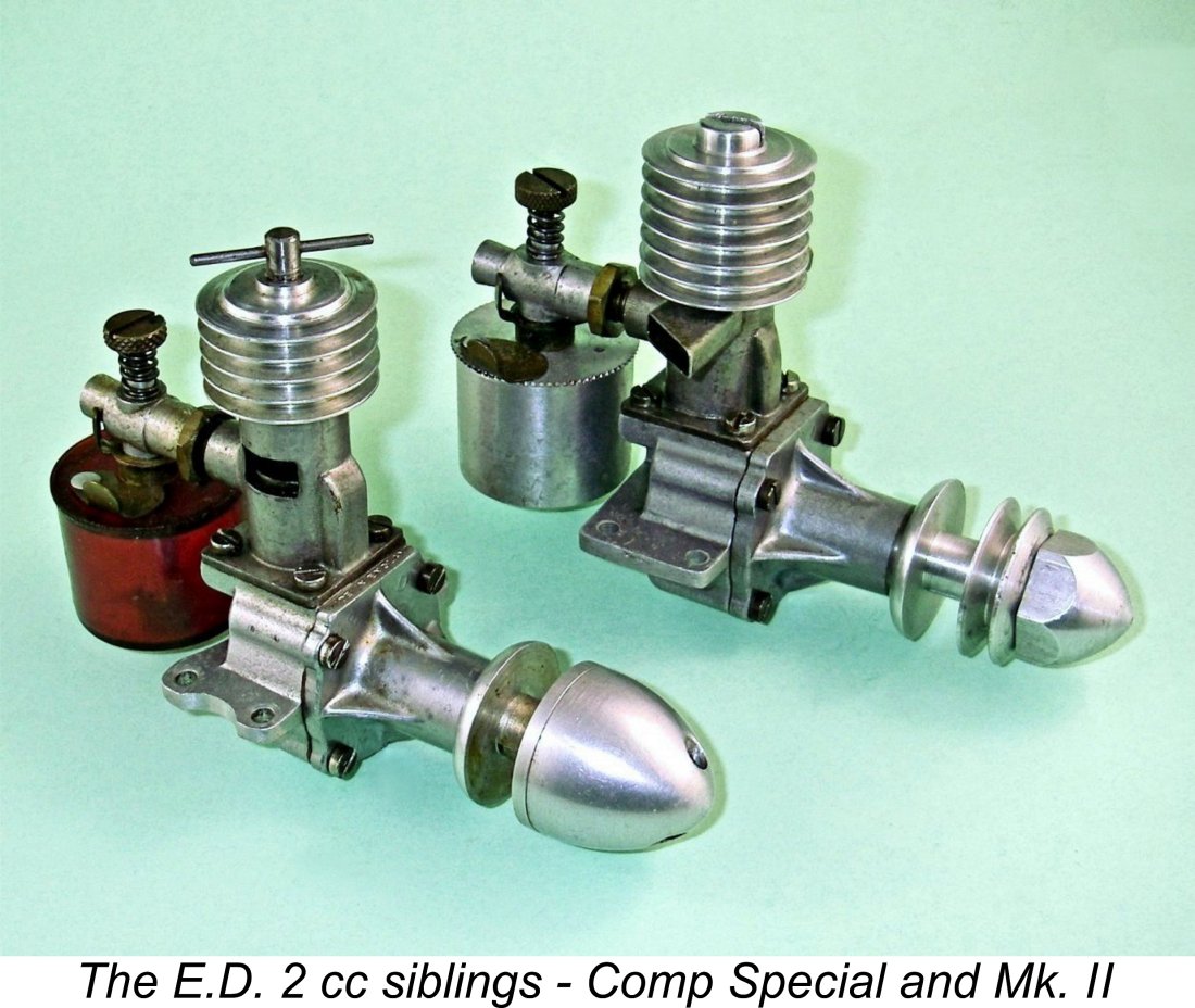 In this article, I’ll attempt to unravel the surprisingly complex history of one of the best-known diesel engines of its early post-WW2 era, the E.D. 2 cc sideport model, in both its original Mk. II and its later Comp Special guises. These were the first model engines to be produced commercially by the famous
  It might be asked why I’ve taken the trouble to subject the E.D. 2 cc series to a detailed review in these pages. Well, for one thing I've received a lot of reader requests to do so! For another, it’s a very interesting story which throws considerable light upon E.D.’s engine development philosophies in their first year or two of existence. That’s the kind of stuff that interests me! Moreover, since these engines survive today in considerable numbers, there are more than a few present or future owners having a direct interest in gaining a better understanding of their examples.
 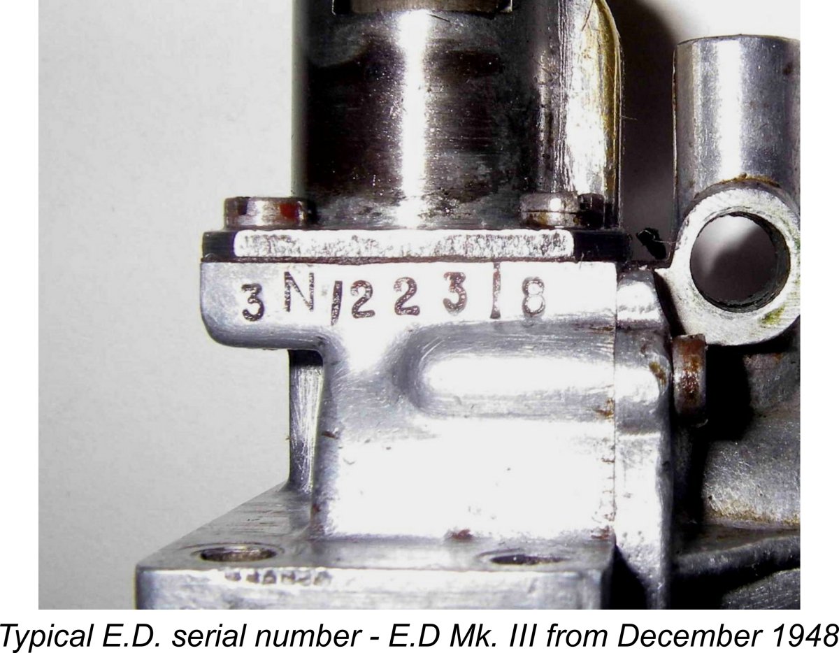 The serial numbers applied to most of the later engine designs produced by the original E.D. company began with a model identification letter or number indicating the particular model to which the number was applied. The example seen at the left begins with the number 3, denoting a 2.49 cc E.D. Mk. III model.
 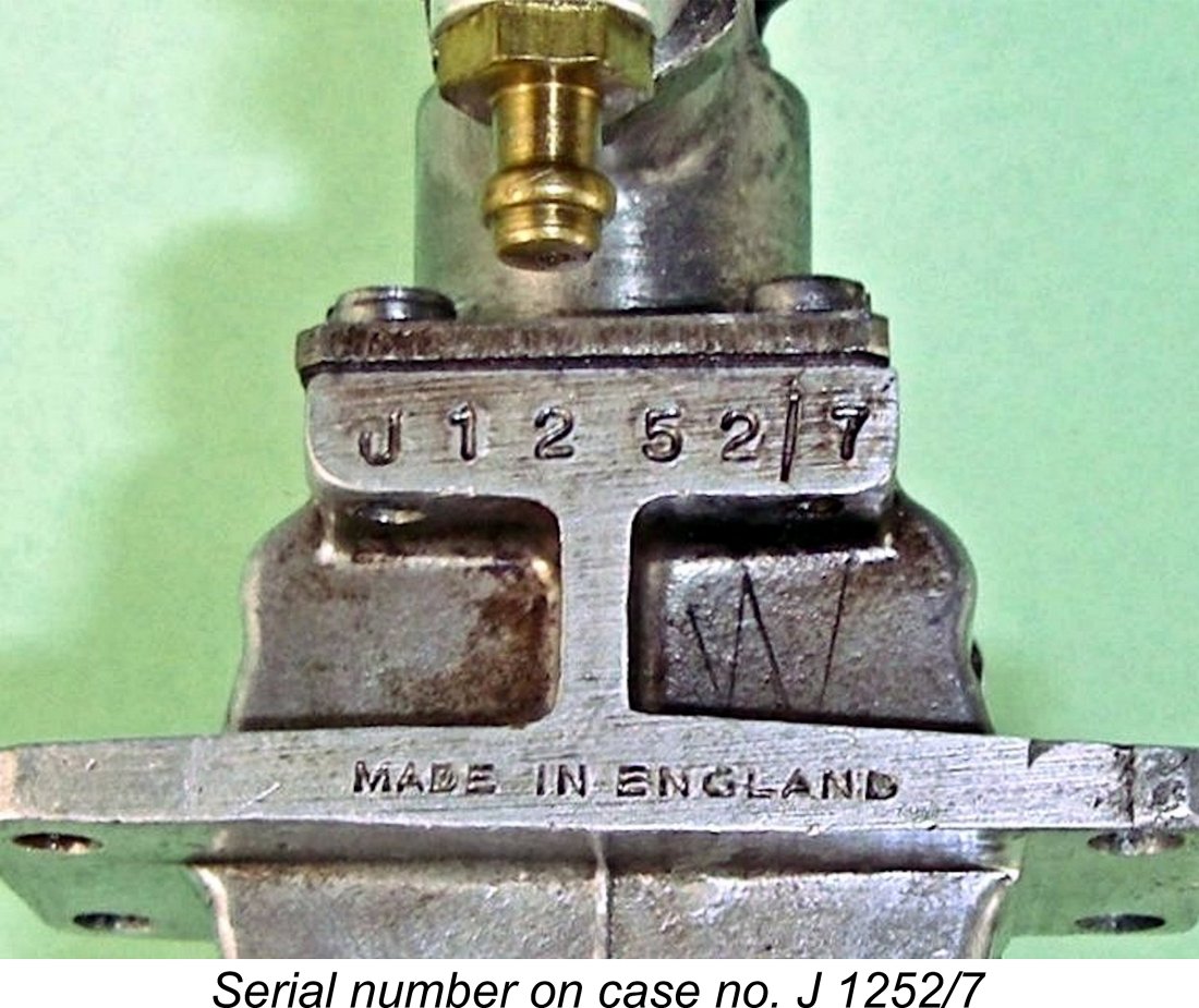 not always) separated from the batch number by a / symbol, although in some cases there was merely a space to indicate this separation. At the conclusion of the 1950s, a change was made to a letter system to indicate the year, with A indicating 1960, B indicating 1961, etc. Otherwise, the system continued unchanged.
 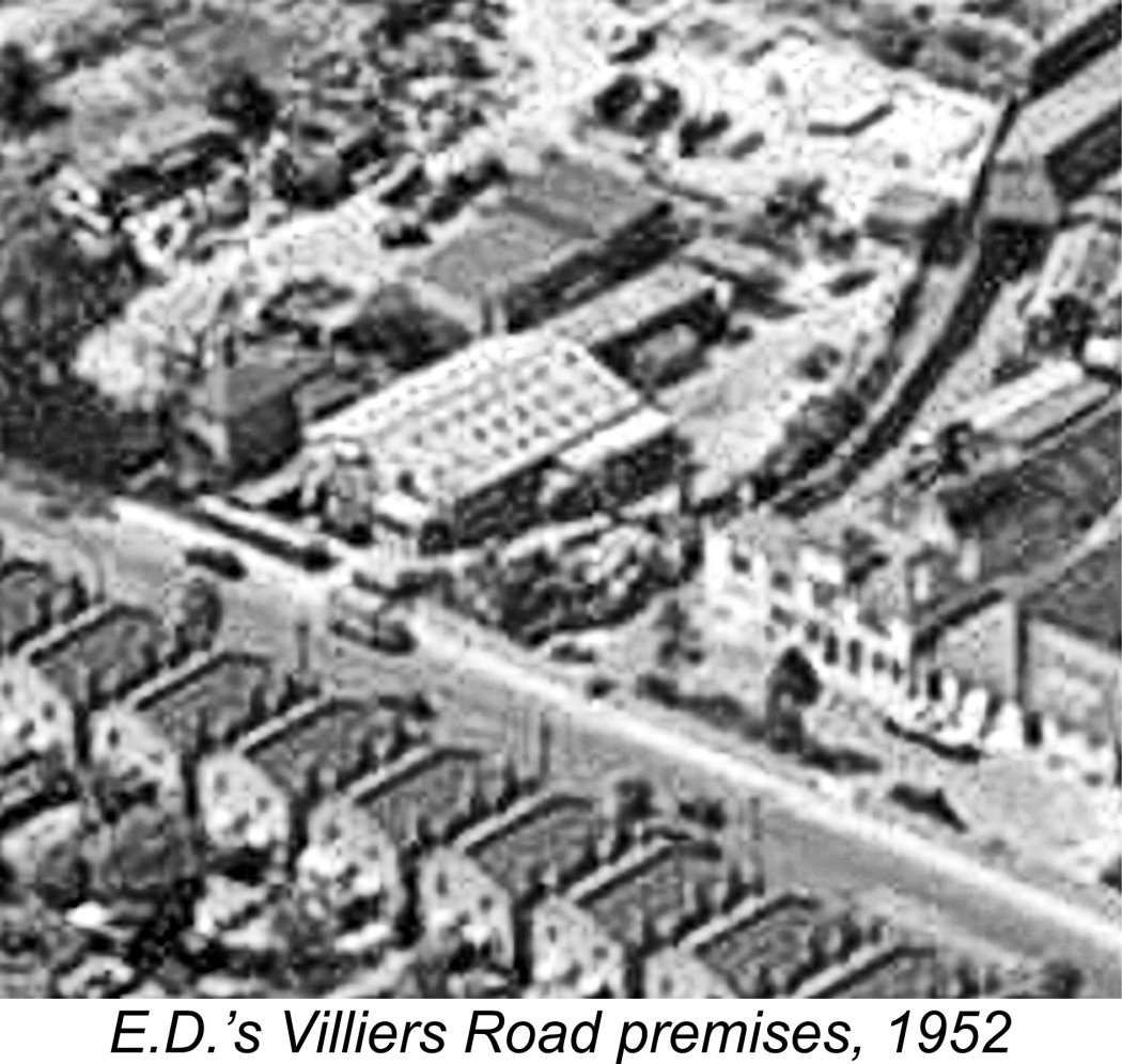 The registered name of the original company which manufactured the E.D. range was Electronic Developments (Surrey) Ltd. This company appeared on the scene in 1946 shortly after the end of WW2, having been formed by a group of individuals who for the most part had worked during the war years for
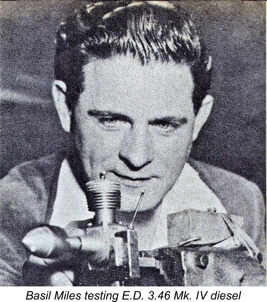
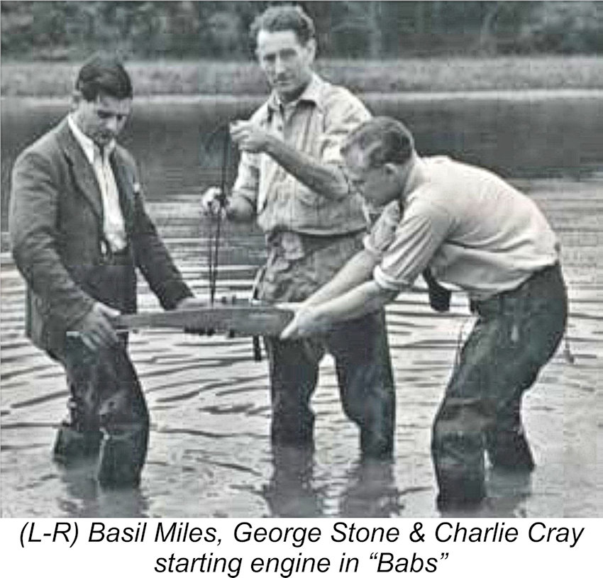
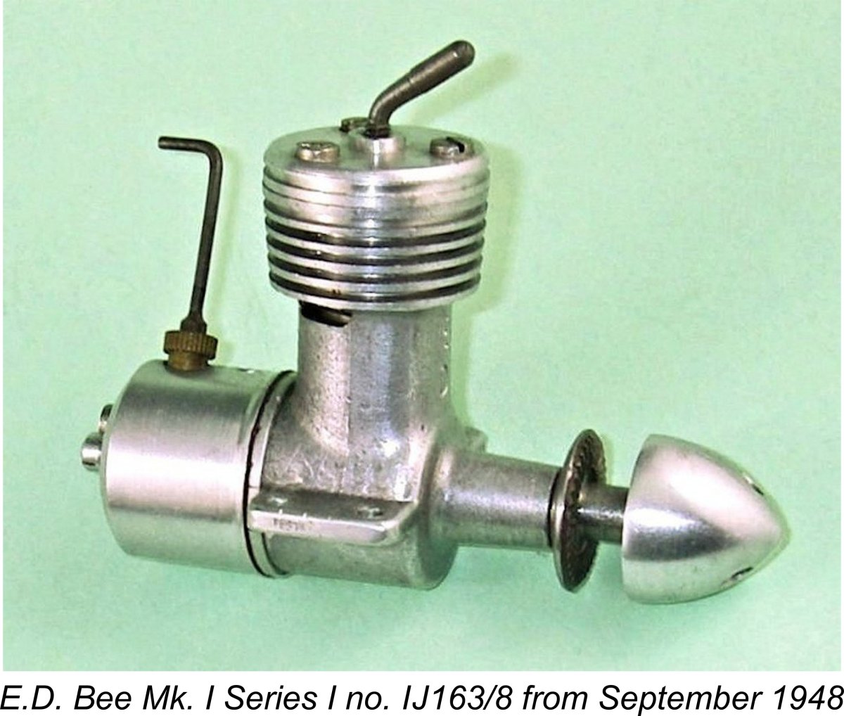 The choice of the E.D. Mk. II designation for the further developed version of the E.D. 2 cc diesel which appeared in February 1947 warrants some discussion here. Since it was E.D.’s first advertised engine, why not call it the E.D. Mk. I? As matters turned out, the engine to which that designation was eventually applied, namely the E.D. Mk. I Bee (“The Engine with a Sting”), did not enter series production until August 1948, and this was well after the appearance of both the Mk. II in March 1947 and the later 2.49 cc Mk. III in March 1948!
 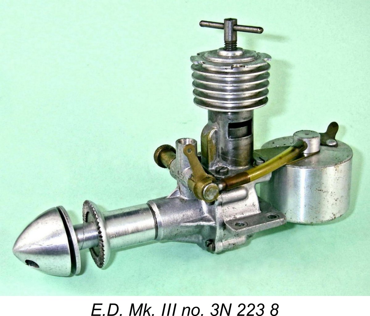 appears probable that the decision to develop the Bee was made long after the Mk. II was well and truly launched. The fact that the Bee first appeared in prototype form in April/May 1948 after the initial appearance of the 2.49 cc Mk. III strongly suggests that the decision to develop a 1 cc model was most likely taken no earlier than late 1947, more or less concurrently with the development and release of the Comp Special.
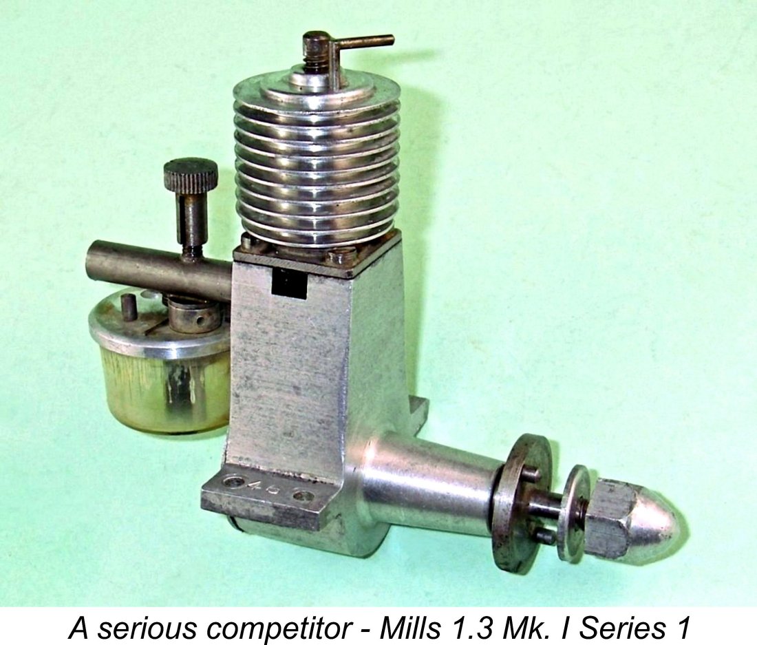 also allow for series production in quantity with a minimal requirement for complex equipment and sophisticated manufacturing techniques, allowing the workforce to gain valuable experience in applying their previously-developed aircraft industry skills to the manufacture of this new type of product using a relatively simple subject.
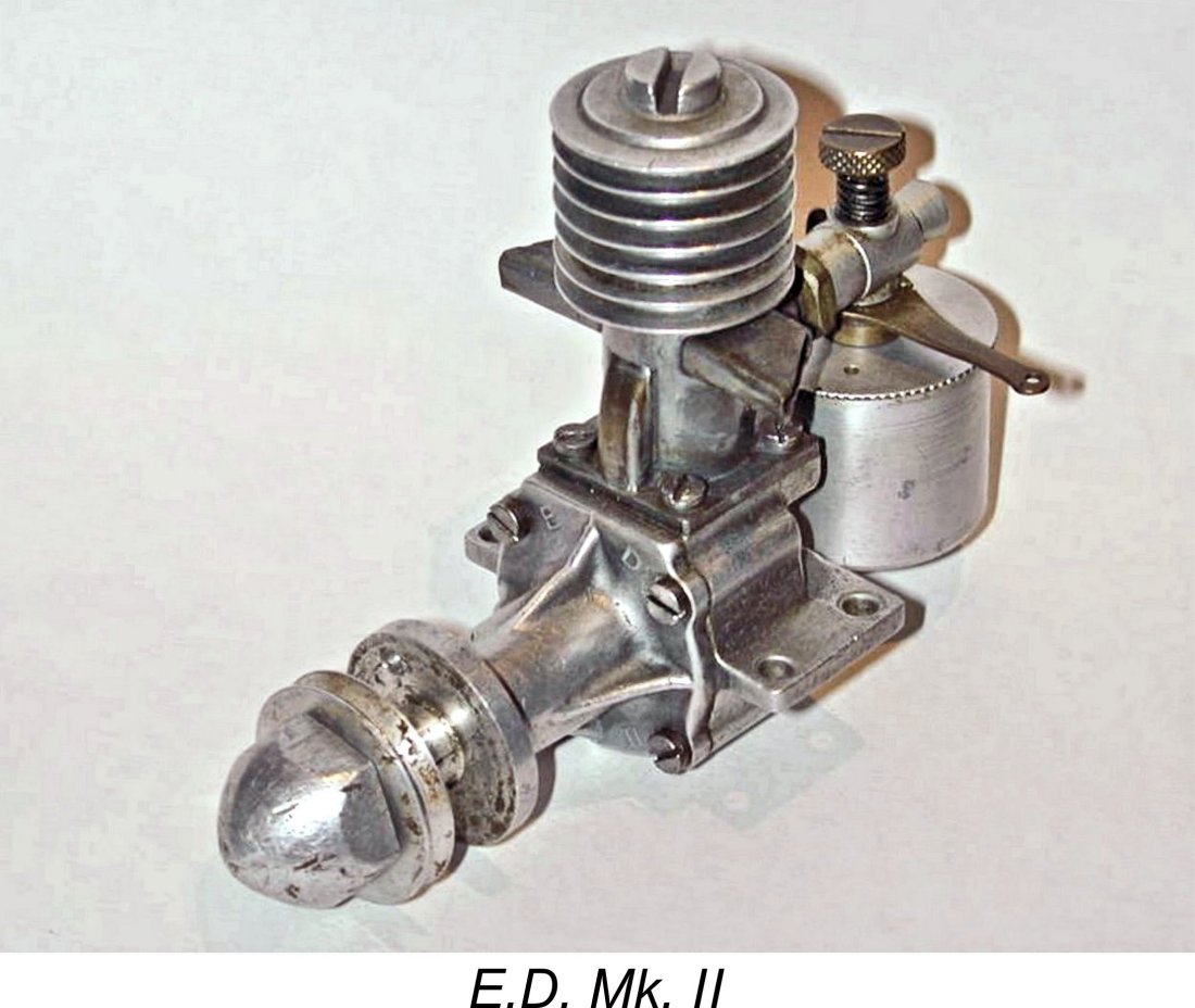 cooling jacket. When this jacket was removed, the cylinder took on the appearance of a length of stove-pipe! Indeed, in North America (where these engines did achieve some recognition for a time as a result of examples being brought back by returning American and Canadian servicemen), the various E.D. 2 cc engines were often colloquially referred to as the “stovepipe models”! Speaking personally, I rather like the name!
 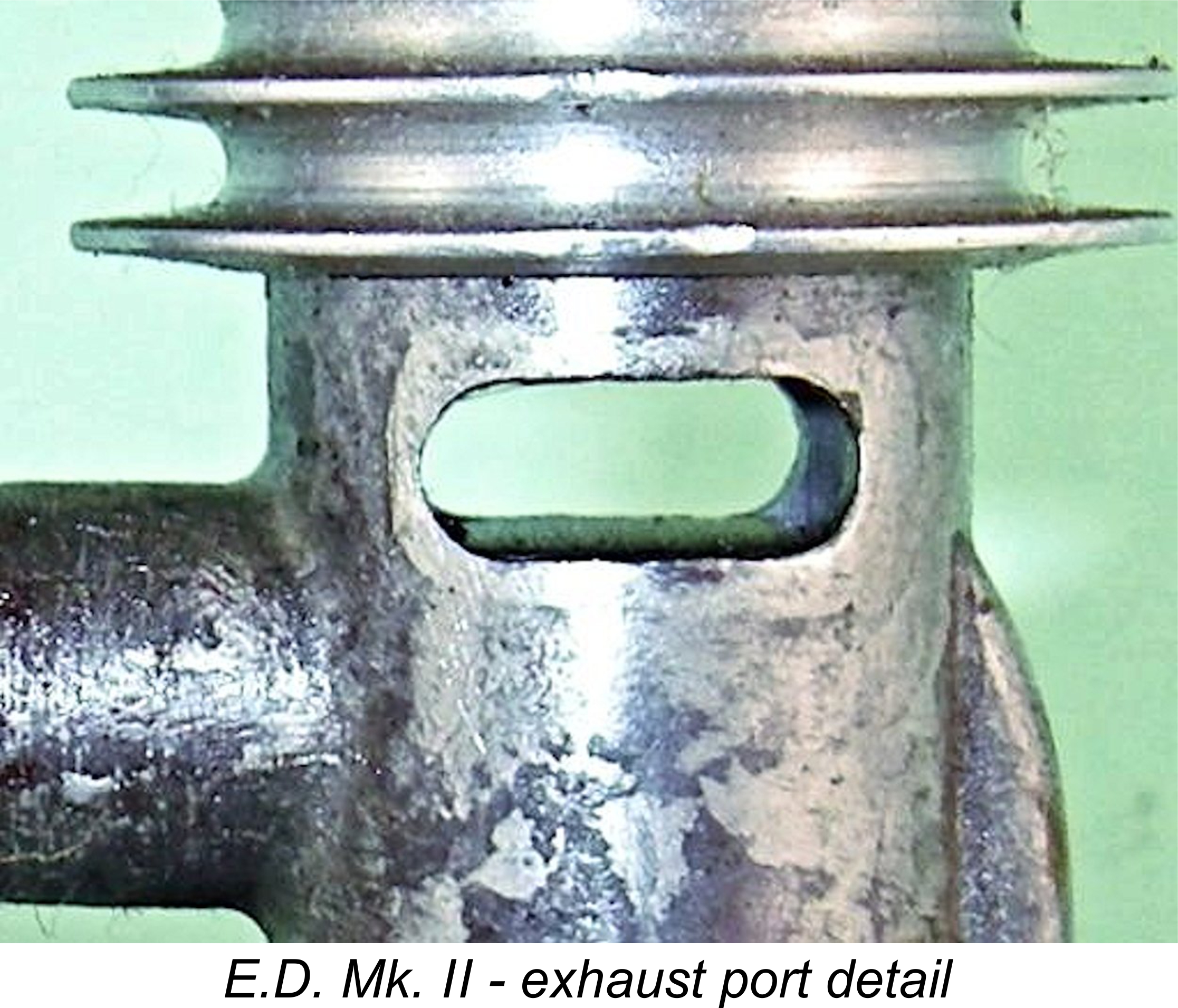 Twin round-ended exhaust ports of generous combined area were provided, one on each side of the cylinder. Most examples of the Mk. II were fitted with exhaust stacks of varying configurations, although a few examples appear to have been sold as new without them. These stacks were also soft-soldered in place.
 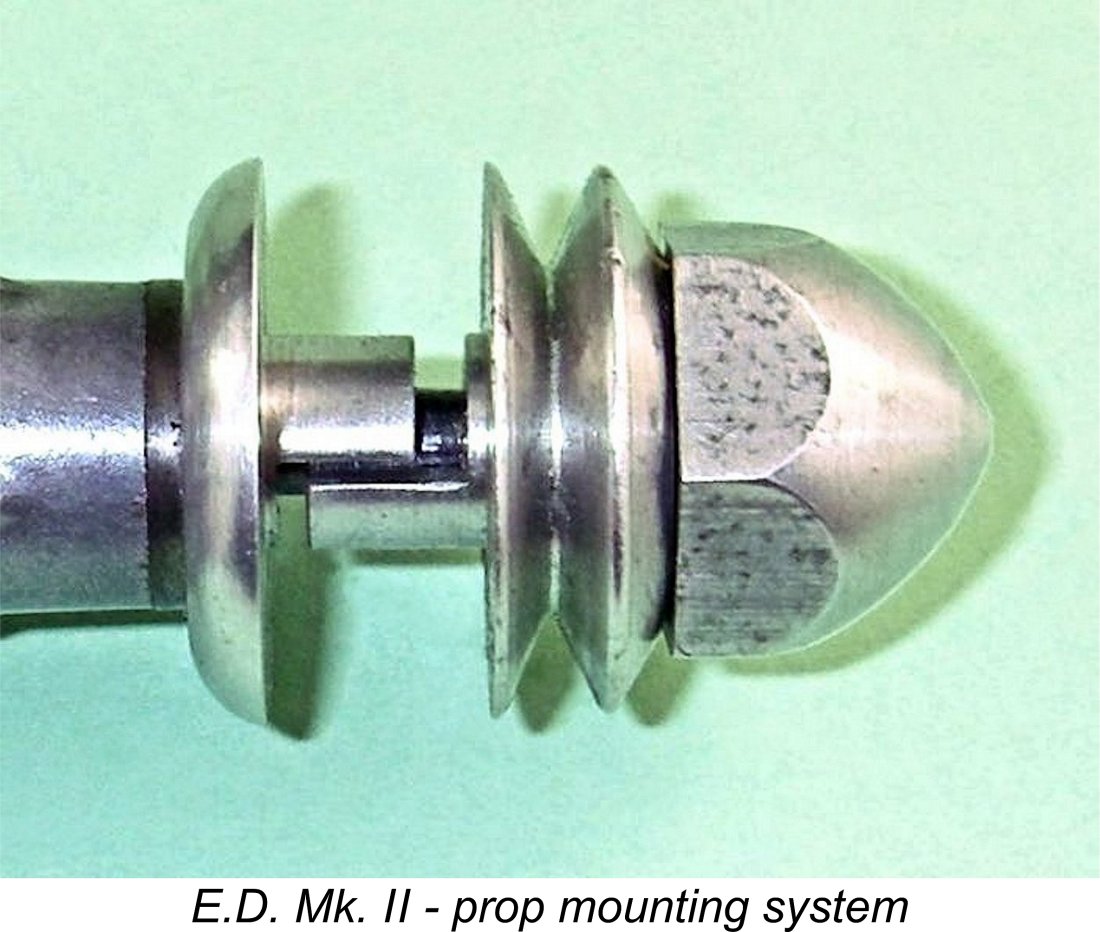 The original E.D. 2 cc model featured a prop driver set-up which was rather different from that used on the Mk. II. The prop driver used on the subsequent Mk. II was a relatively complex two-component item. The rear component was a conventional plain prop driver of generous diameter which was drilled through at shaft diameter but which also featured a square-section socket at the centre rear. This socket dovetailed with a square section milled onto the crankshaft in front of the main bearing journal. This constrained the prop driver to turn with the shaft.
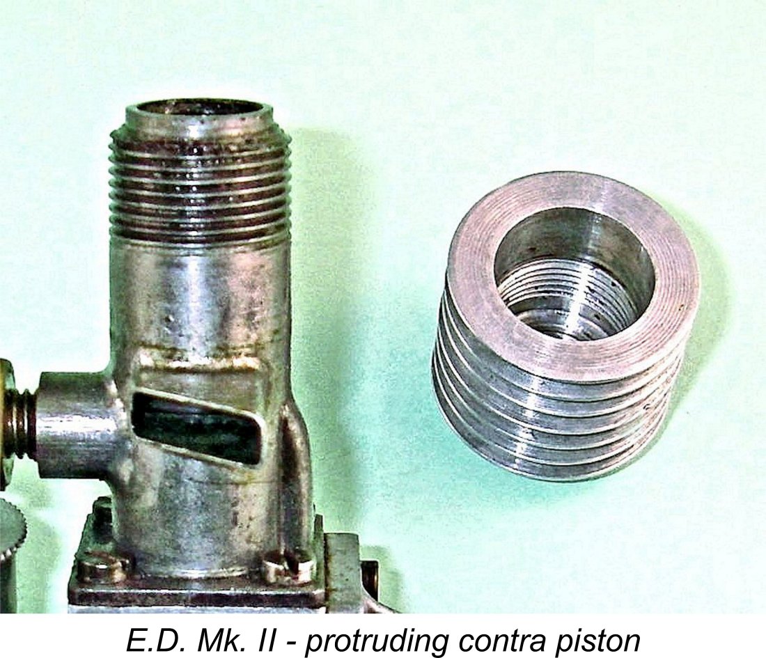
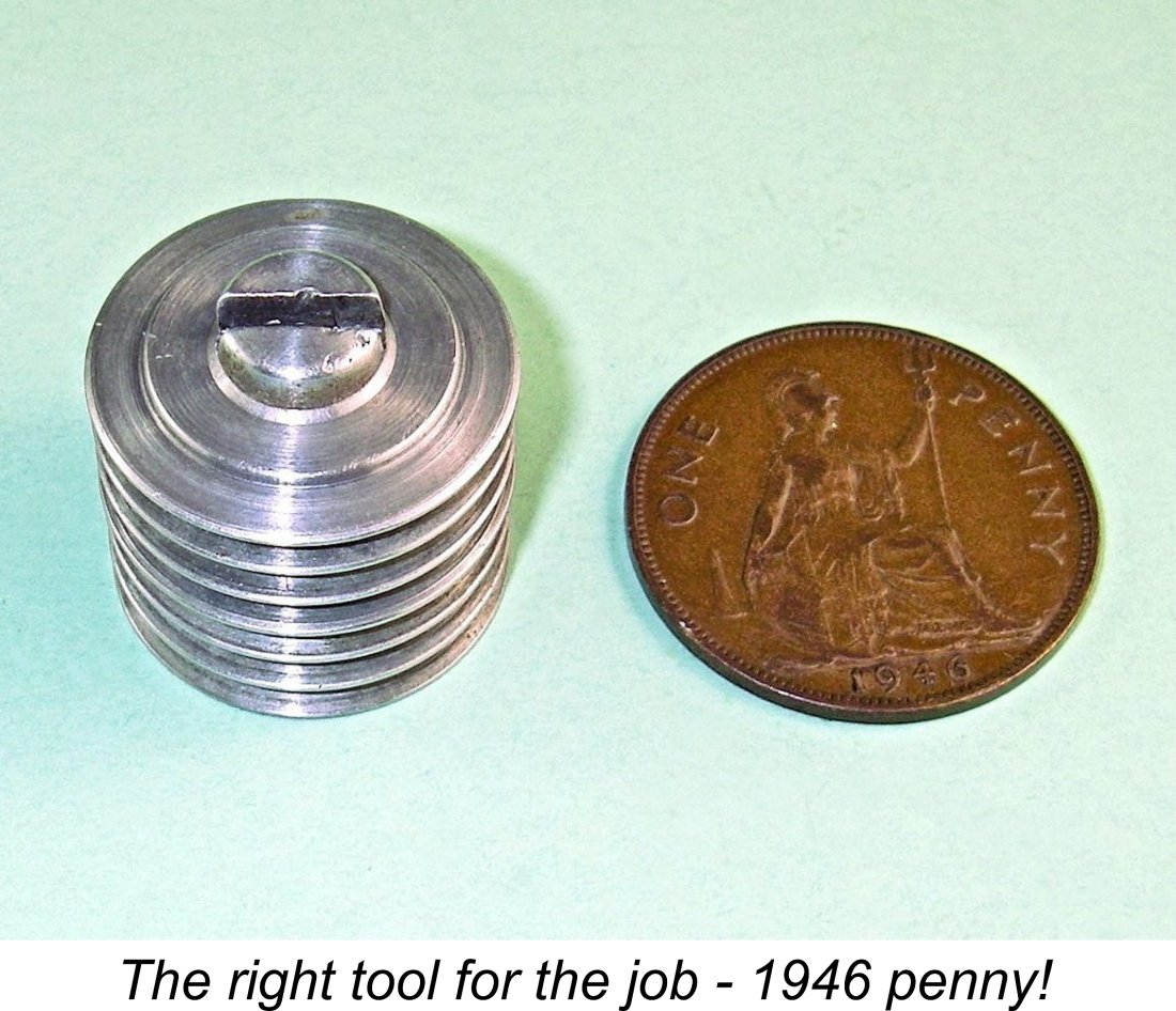 actually running! The Mk. II was fitted with a contra-piston to allow for compression variation, but the familiar and highly convenient compression screw and tommy bar were absent. Instead, compression adjustment was made possible simply by the separate screw-on aluminium cooling jacket making direct contact with the top of the contra-piston, which was dimensioned so as to protrude above the top of the cylinder at running settings.
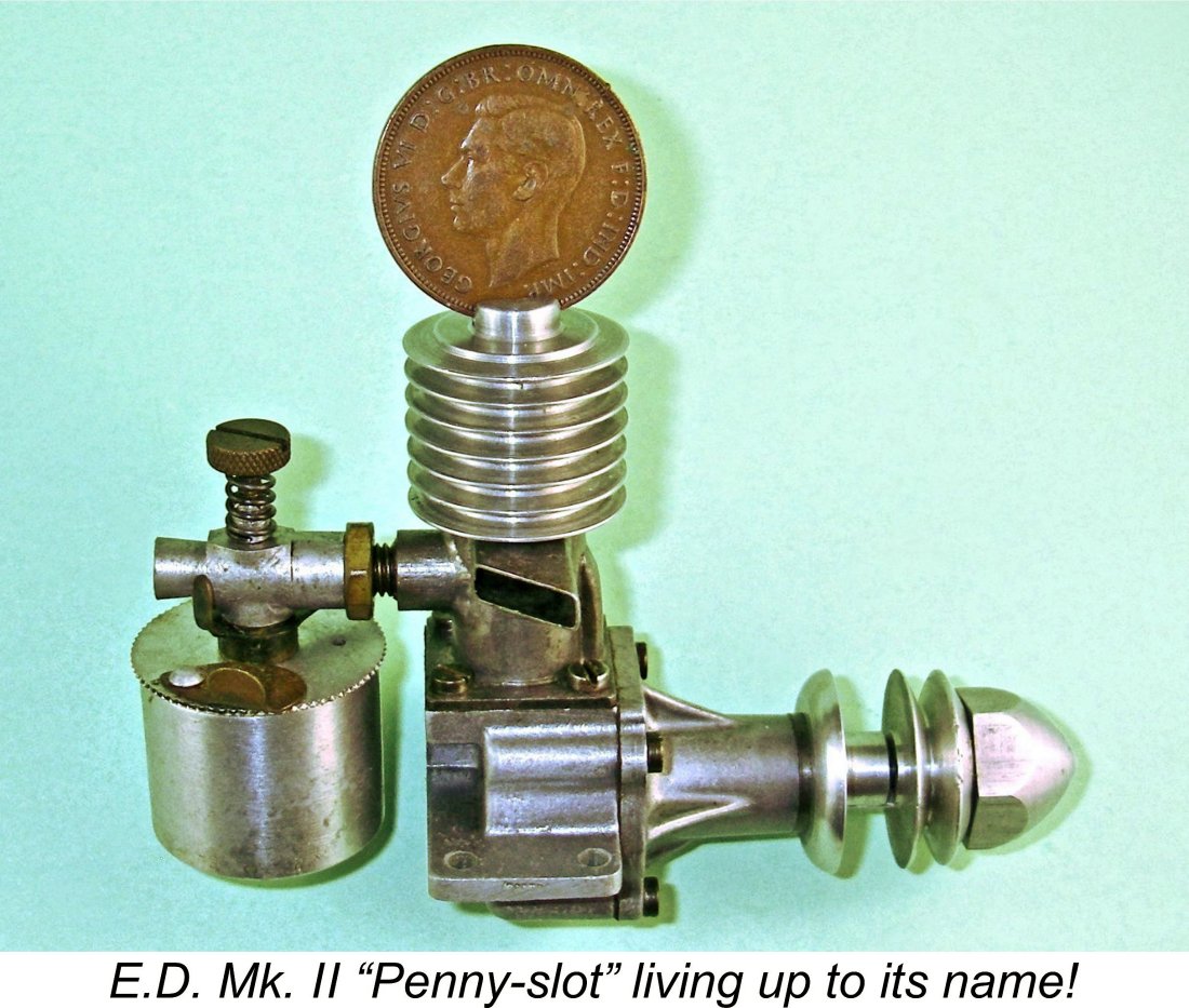
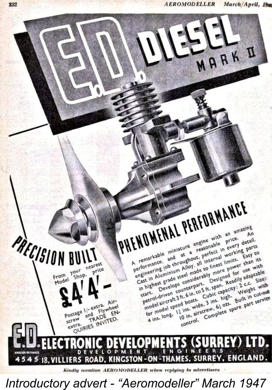 The earliest “named” example of the E.D. Mk. II of which we are aware is serial number B 23/7. Those who have followed my earlier advice by making themselves familiar with the E.D. serial numbering system will immediately recognize this engine as dating from February 1947 and being the 23
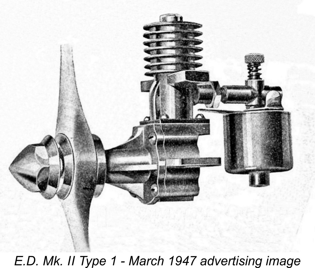 The conrod used in this engine was of square section as opposed to the round section item used later. It operated through a fairly narrow slot milled into the top of the crankcase directly above the crankpin, as seen in the image below at the left. This slot also provided the sole means of gas flow communication between the lower case and the transfer entry, consequently representing a significant impediment to the free movement of mixture from the lower crankcase into the transfer system.
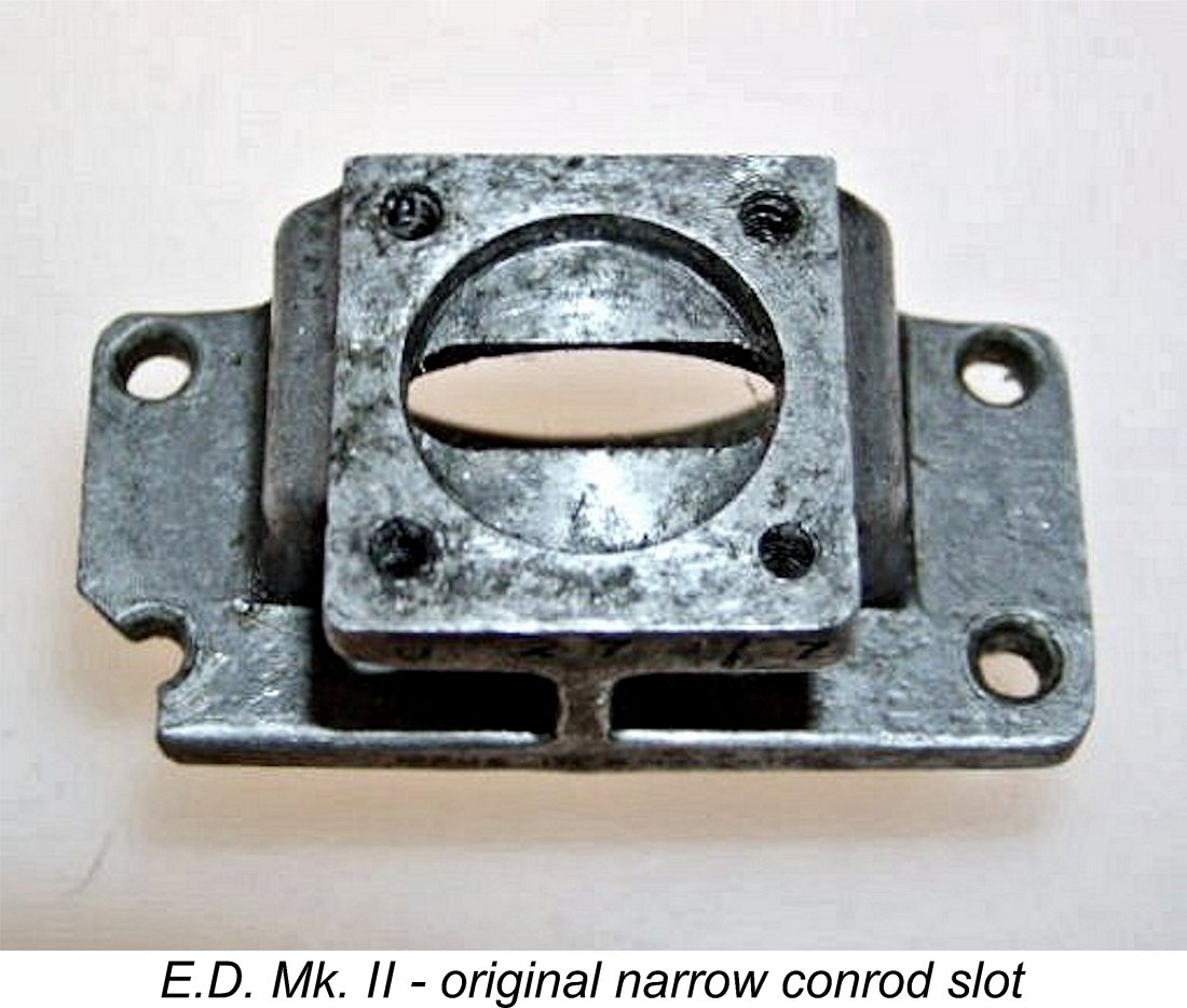
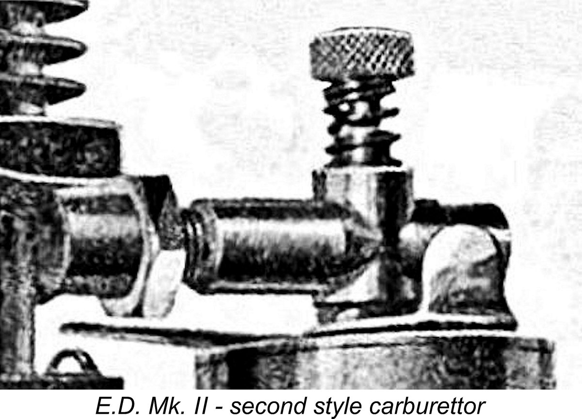
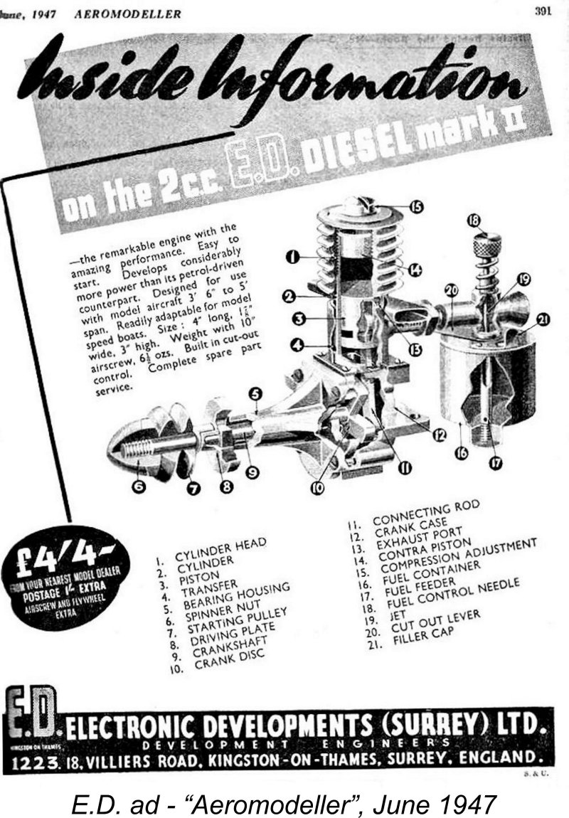 The Type 2 engine had round-edged exhaust stacks, the outer faces of which were not cut at an angle like those of later versions. In all other respects, the engines remained the same as the Type 1 versions described above. We are acquainted with engine numbers C 182/7, D 46/7 and D 430/7 which are of this type.
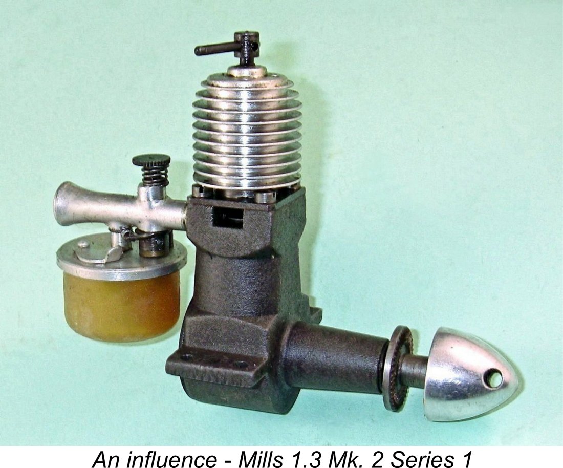
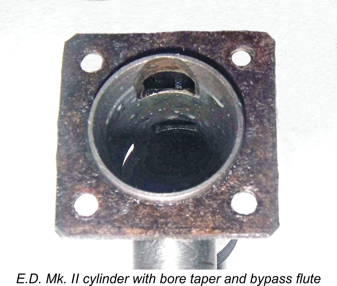 It's evident from the steps that they took that E.D. had by now recognized the major Achilles’ heel of the Mk. II as it then stood. This was the bypass/transfer system, which was undeniably rather constrictive in nature. It seems strange that it took them so long to recognize this issue, but recognize it they finally did, and three significant modifications were now introduced in a somewhat tentative attempt to deal with the problem:
 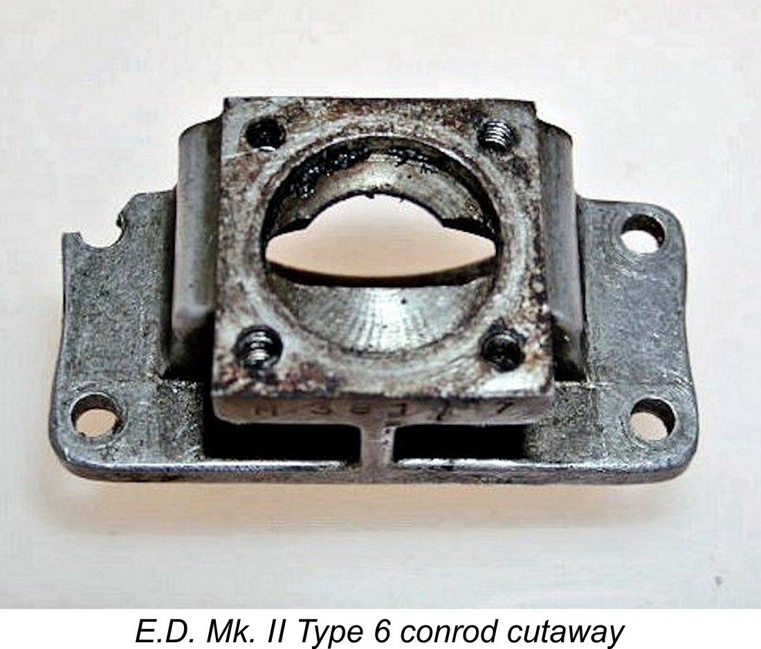 In theory at least, the system described above rendered the previously-used piston skirt port unnecessary, and it was accordingly omitted. The above transfer arrangements were (in principle at least) to remain in use for the remaining production life of the engine.
 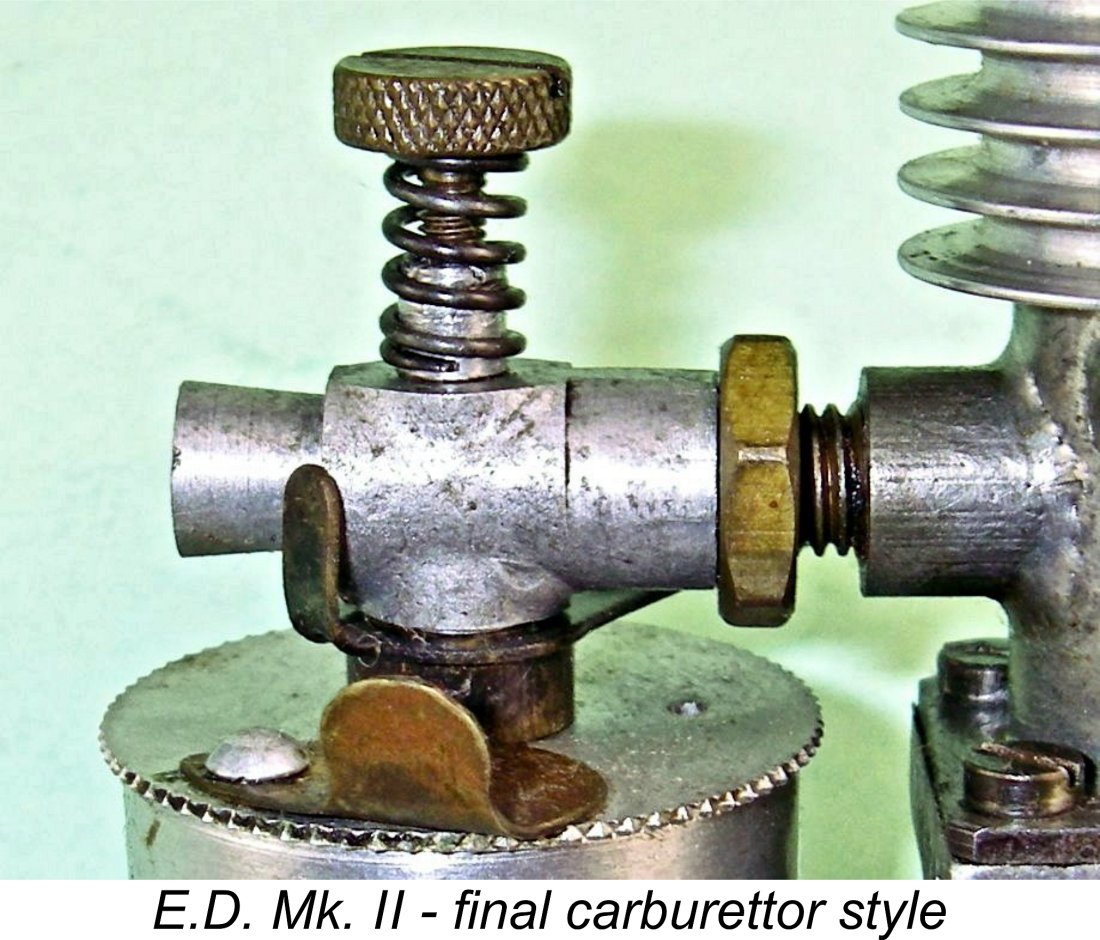 Finally, this version of the engine introduced the familiar rectangular-section stacks for the first time, replacing the round-edged stacks which had been used previously. These rectangular stacks were cut back at a rearward angle at their outer ends. They were to remain the standard fitting for the rest of the Mk. II’s production life.
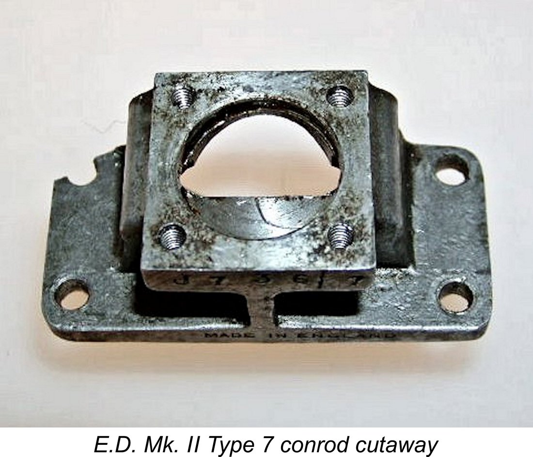
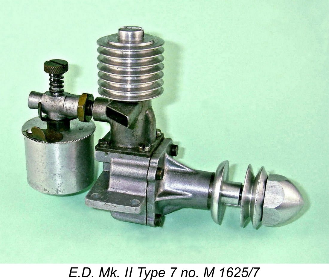 J 1252/7 confirms the production of at least 1252 examples in September 1947. In addition, engine number K 2077/7 confirms that over 2,000 examples were produced in October 1947. This variant was to survive right through to December 1947, being produced in quite large numbers throughout – engine number M 1755/7 from relatively late in the November 1947 batch remains of Type 7. Clearly the pace of change was slowing by now as the bugs were being successively worked out and the design was moving ever closer to its final form. Production figures continued to be quite impressive!
 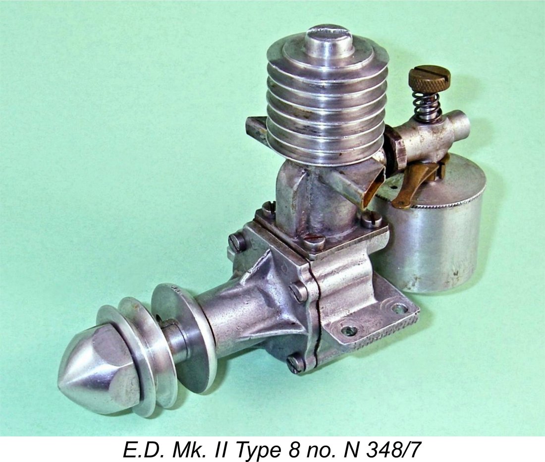 The answer of course was the addition of sub-piston induction, whereby the lower portions of the two exhaust ports were briefly opened by the bottom of the piston skirt at top dead centre to allow extra air to pass into the crankcase at the point of maximum crankcase volume. It was decided that this feature should be added to the design.
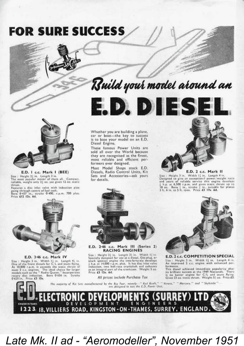
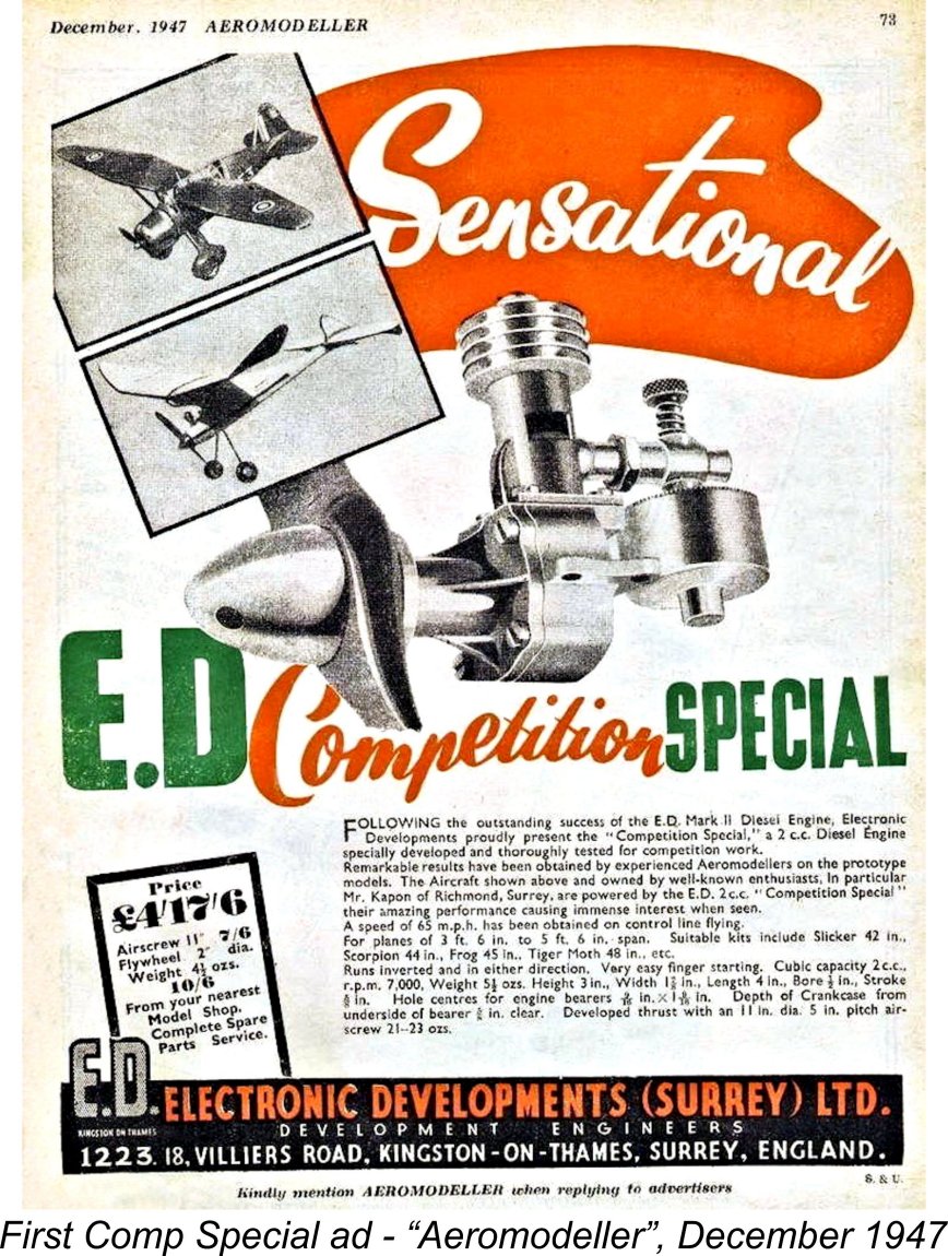 In the earlier discussion of the Mk. II, I commented upon the probable basis for E.D.’s decision to present the improved model as an entirely new product rather than simply applying the various improvements to an updated version of the Mk. II. I suggested that there were good reasons for this strategy being adopted.
 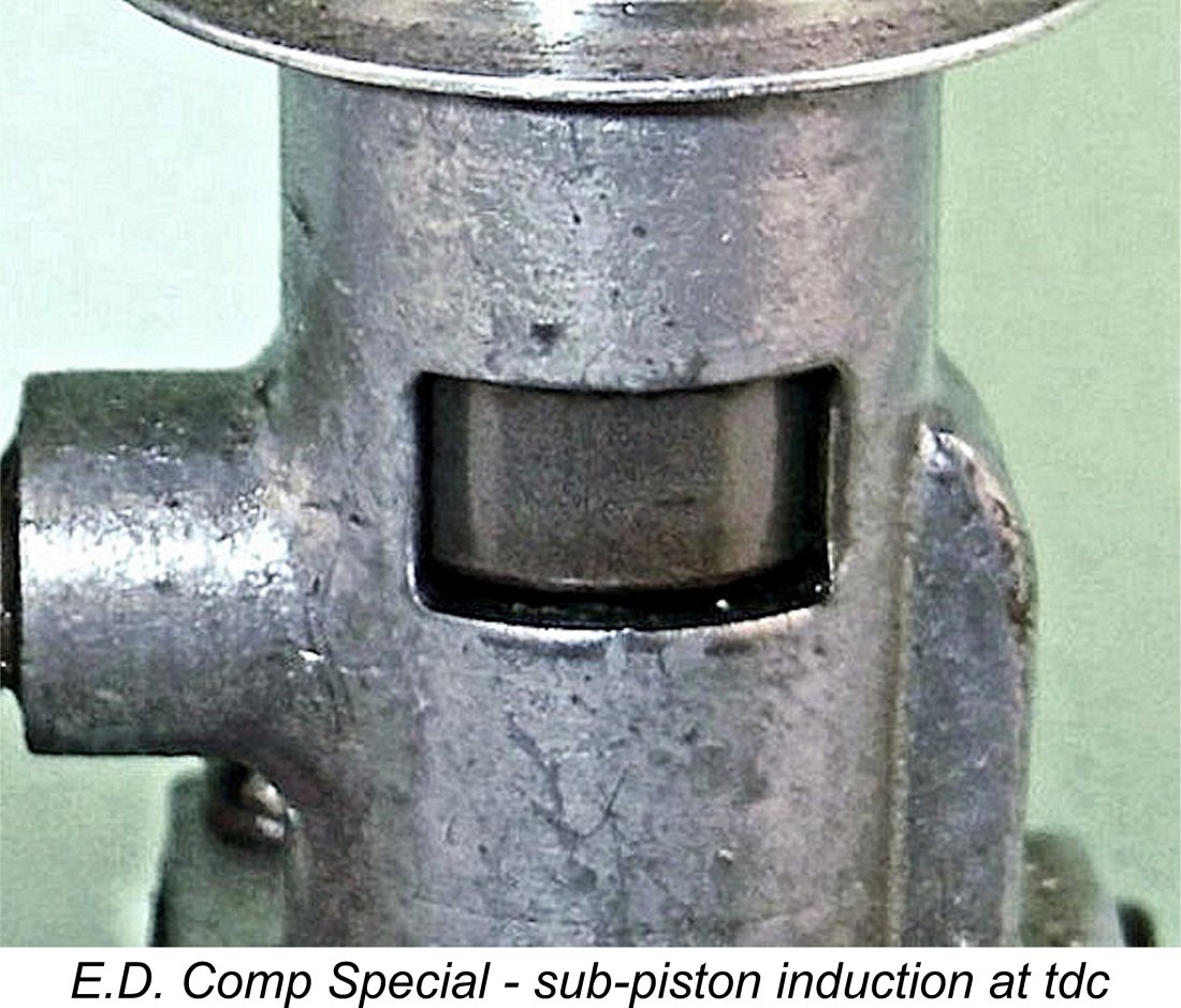 The above improvements were applied to the new Comp Special and were also added to the Mk. II, resulting in the Type 8 variant of that model described earlier. But E.D. did not stop there with the Comp Special. A third modification introduced on the Comp Special which was also related to the engine’s “breathing” at higher speeds was a downward extension of the already-generous exhaust ports to give a relatively short but potentially significant period of sub-piston induction around top dead centre. To maximize the effectiveness of this change, the enlarged ports were cut to a rectangular plan as oppposed to the Mk. II's round-ended oval shape.
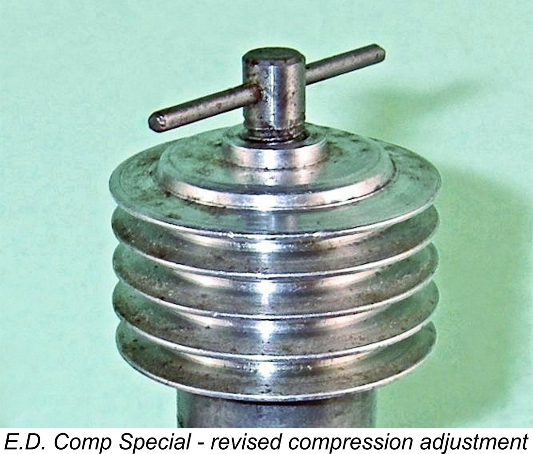
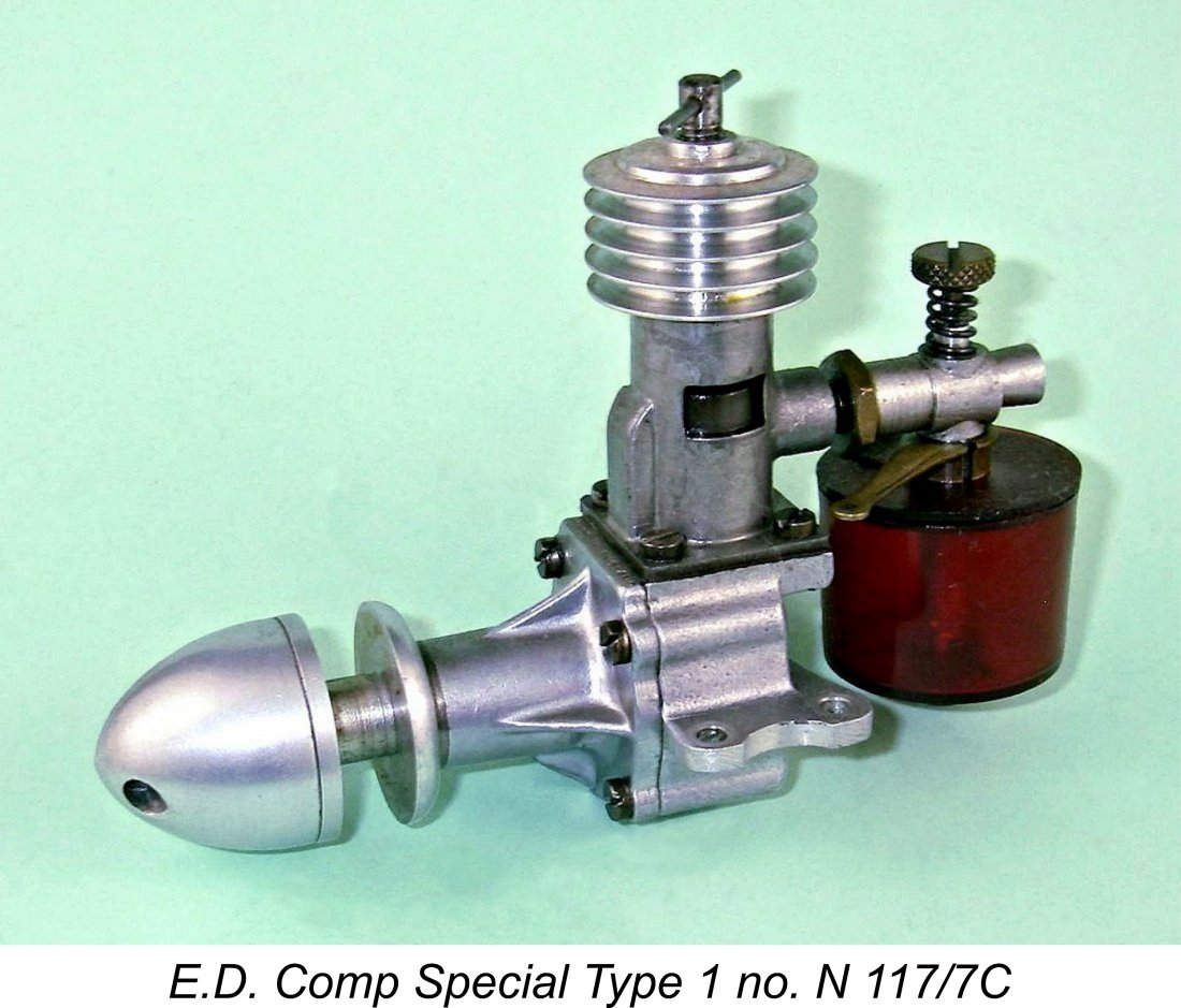 The earliest example of the Comp Special with which Kevin and I are directly familiar is engine number N 117/7C (from the December 1947 batch). We also have access to engine number N 164/7C from the same batch. Both engines use a plain two-piece prop-driver and a gravity die-cast case, also retaining the lever-style cut-out as used on the Mk. II. They use a compression screw which has a very spindly-looking tommy bar of only 1/16 in. diameter. This “thin bar” compression screw was also to be used a few months later on the introductory versions of the 2.49 cc crankshaft rotary valve E.D. Mk. III.
 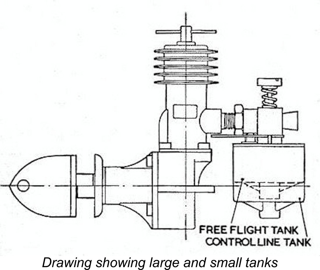 It would appear that supplies of the shallow-depth tanks were rather limited and that that only the earliest examples of the engine were supplied with such tanks. The two tanks are not directly interchangeable on the same engine – the shallower tank requires an alternative carburetor unit with a shorter fuel pick-up tube (upon which the tank is mounted).
 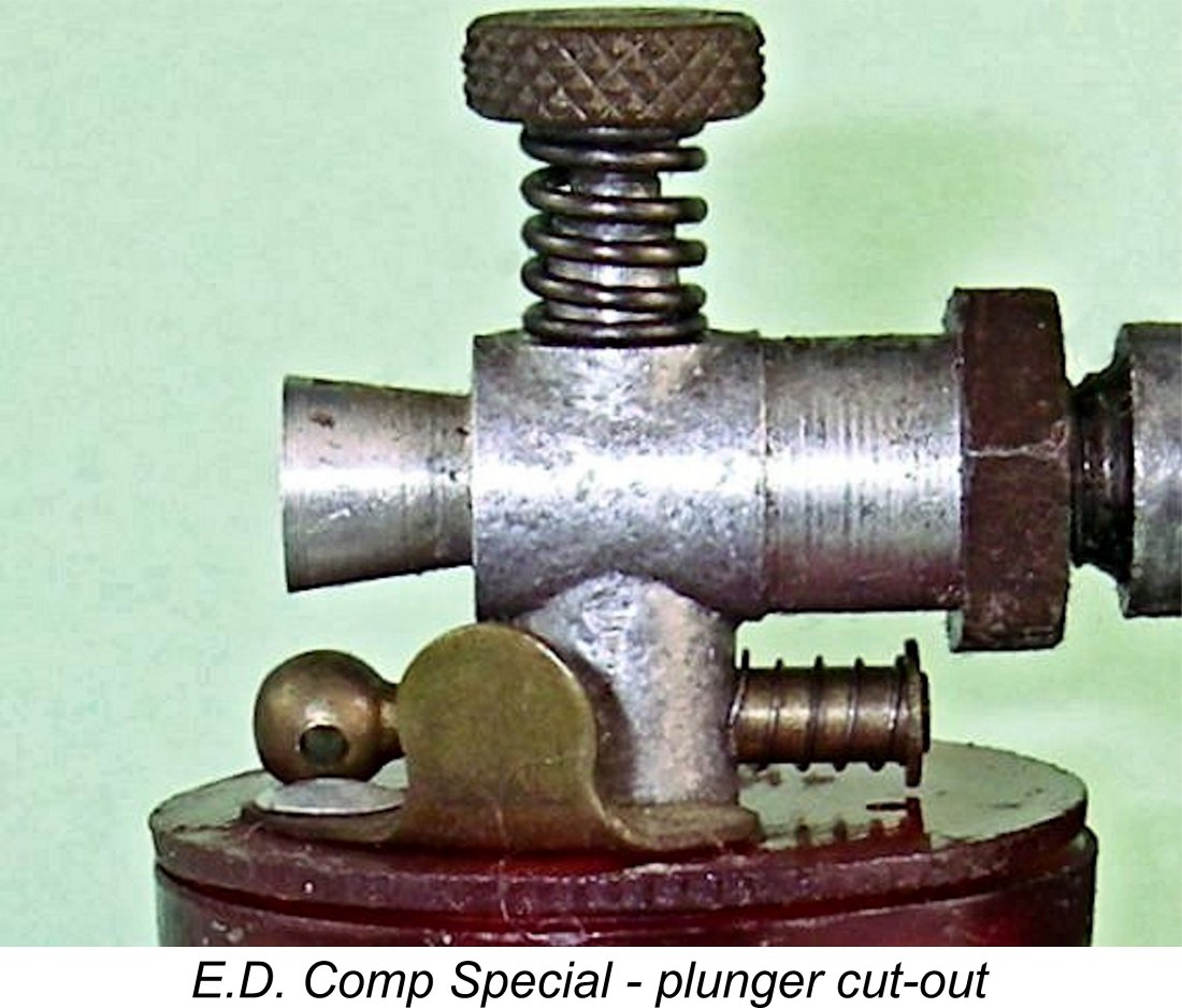 At some point between June 1949 and April 1950, a significant change appeared in connection with the carburetor arrangements on the Comp Special. The lever-type air-bleed cut-out which had up to then been applied to both the Mk. II and Comp Special was dropped on the Comp Special in favor of a spring-loaded plunger-type cut-out. This operated by directly interrupting the fuel line as opposed to the former system of bleeding air into the fuel line to destroy suction. As such, it might be expected to be more positive in action.
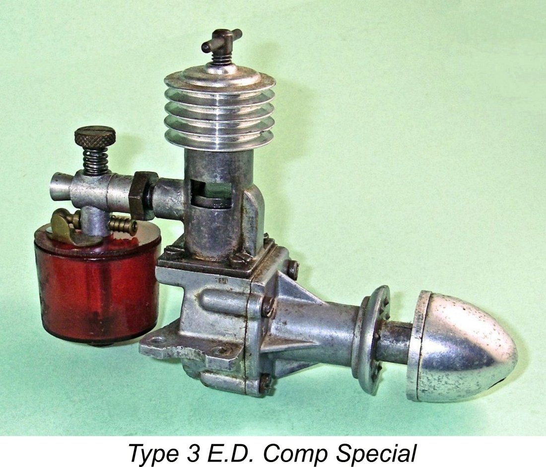
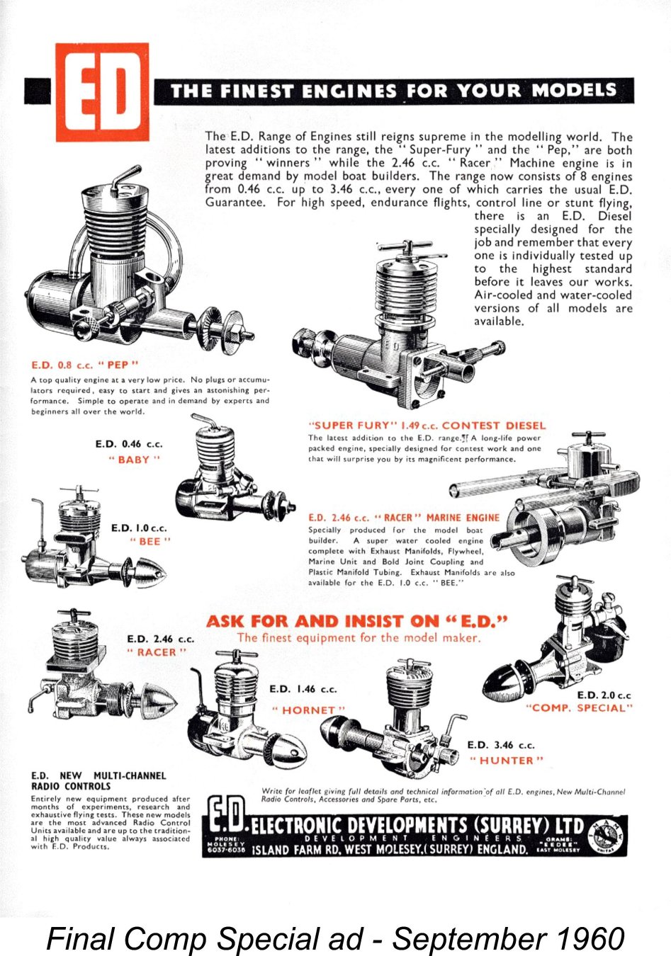
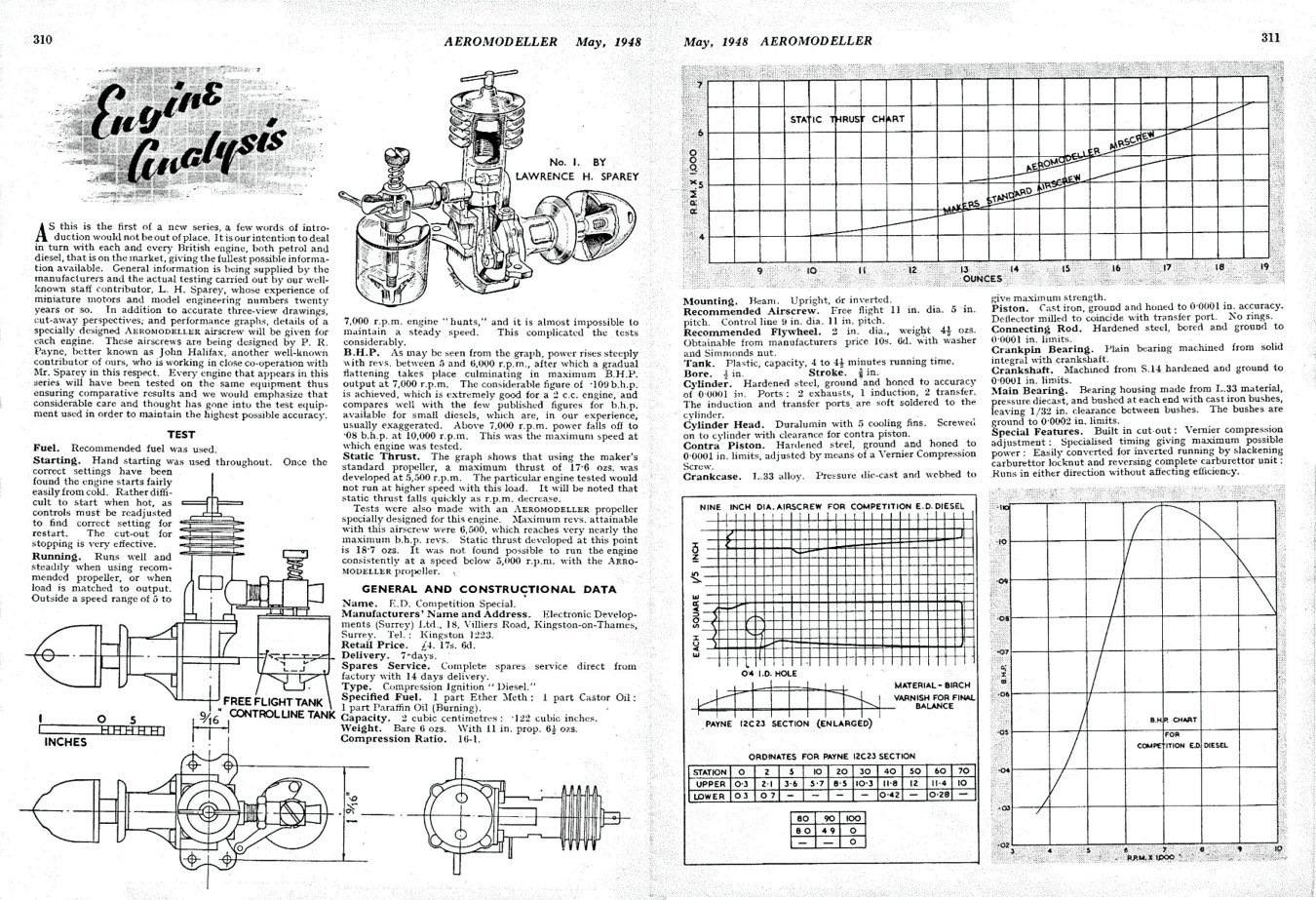
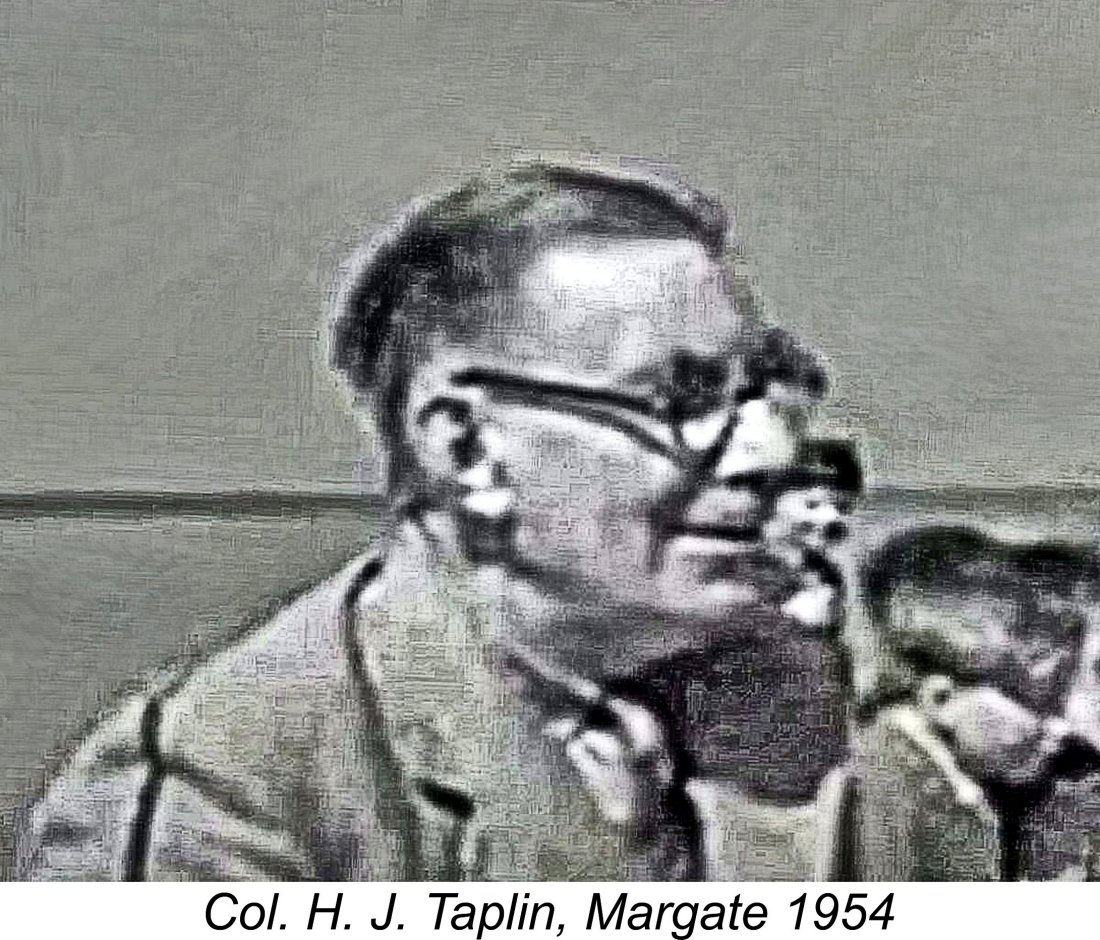
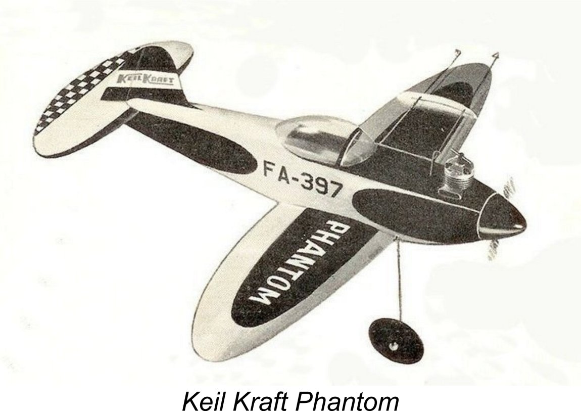 The Taplins' record had been set using a low-wing trainer-style model built along
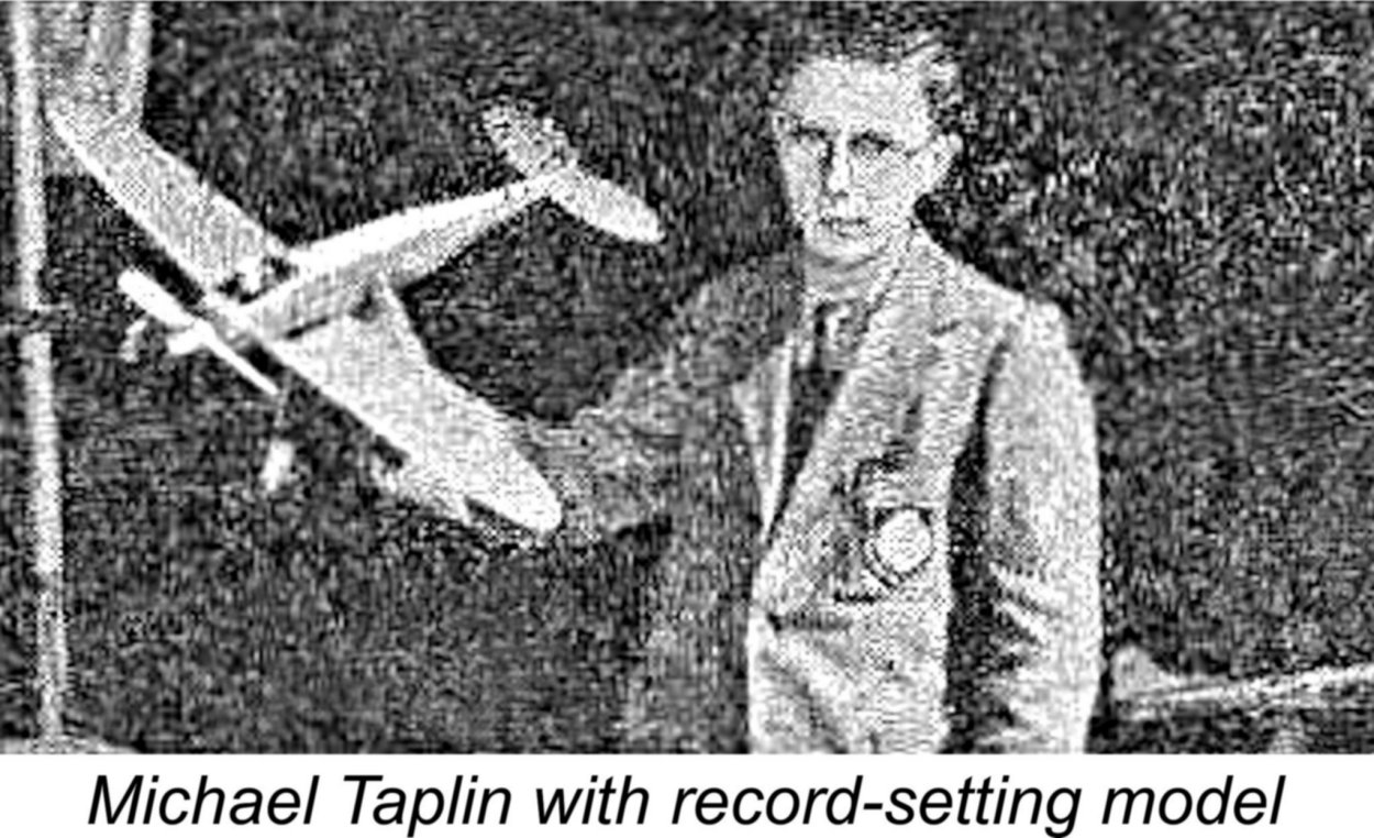
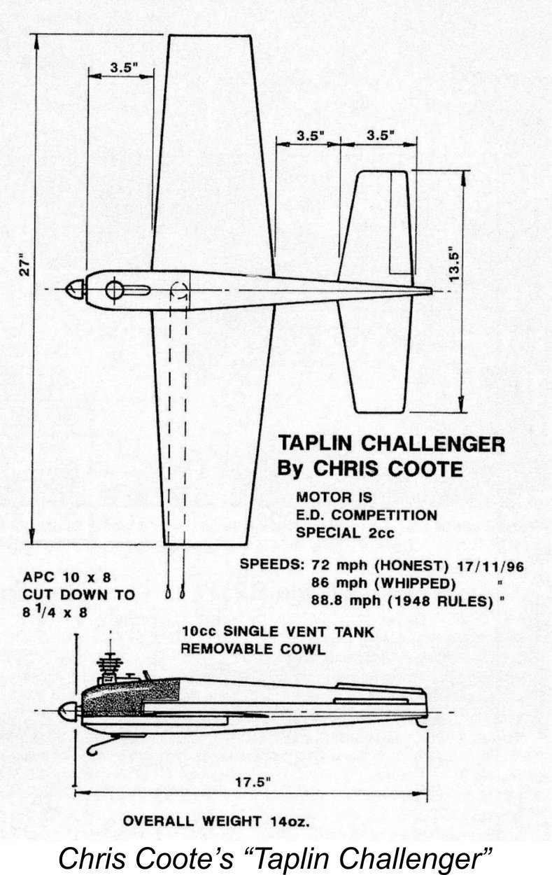
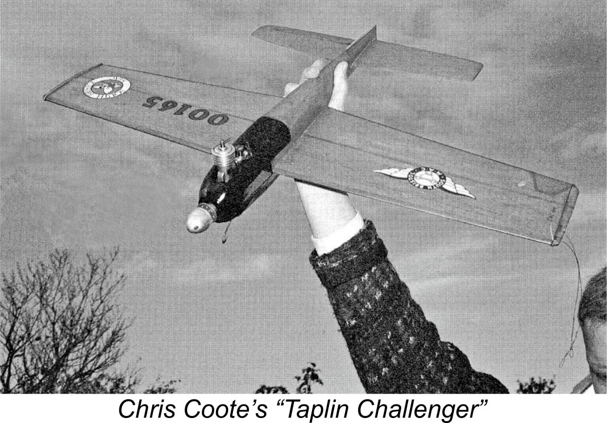 Anyway, Chris converted an old FAI team racer to accept his own Comp Special no. N 1238/8C (December 1948). This 27 in. span model was modified to resemble the Taplins' model as closely as possible, including the upright engine with exposed cylinder and the removal of the tail fin. The major difference was that Chris's "Taplin Challenger" lacked a fixed undercarriage, instead featuring a wire front landing skid. This might be expected to reduce drag somewhat.
 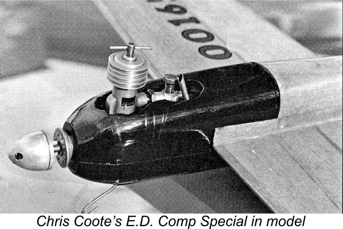 Frankly, I had a great deal of trouble imagining a standard Comp Special managing such a feat! My own previously summarized test results on my best standard Comp Special are better than those reported by Lawrence Sparey - my engine seems to be a good 'un! The figures show conclusively that at 9,900 rpm even a good example of the standard Comp Special is well past its peak, power having dropped to only around 0.094 BHP from its peak of some 0.124 BHP @ 8,000 rpm. The engine can't even manage 9,900 rpm on the bench with a "fast" Taipan 8x4! Frankly, I found this data very difficult to reconcile with Chris's cited 75 mph figure - surely it would take more than 0.094 BHP to pull a model around at that speed without help?!?
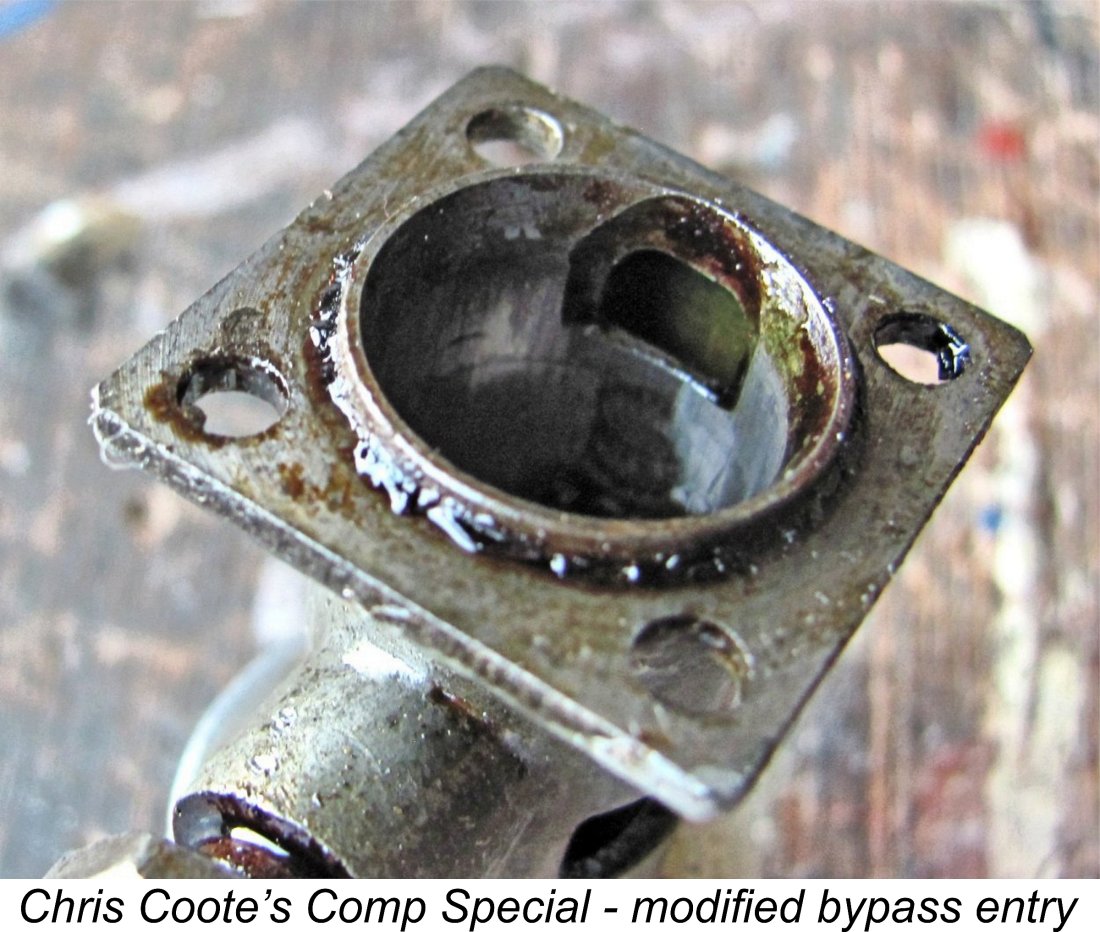 I had no doubt at all that Chris had indeed achieved the claimed 75 mph speed. The question was - how?!? After thinking about this for a while, I came to the conclusion that Chris's engine must be modified, a view which I shared with Chris. He had never torn it down to check, simply assuming that it was stock. He now did so, finding that it is modified, just as I had predicted! The lower piston skirt is unmodified, but Chris's attached image shows that the internal bypass flute at the cylinder base has been greatly enlarged and the lower entry into the bypass passage itself has been extended downwards.
 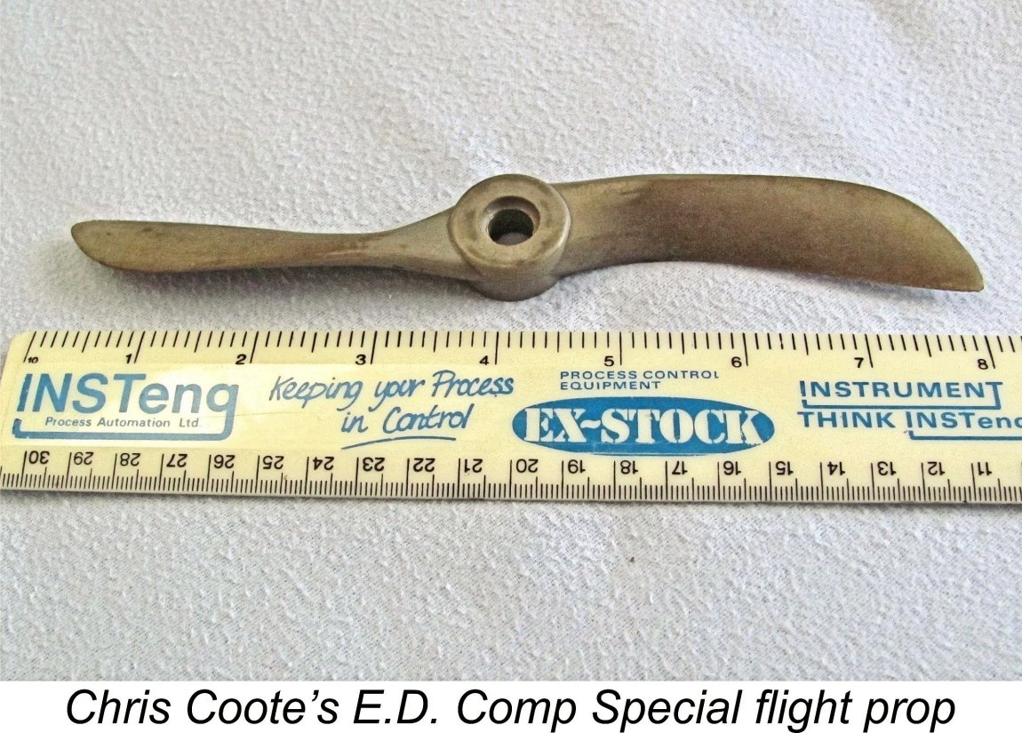 At my request, Chris was kind enough to set his engine up on the bench to check its performance. He found that it turned the cut-down and trimmed APC 7¾x10 flight prop at 7,240 rpm, which seems just right for an airborne pickup into the 9,000 rpm range with a low-drag model on short skinny lines. Of greater relevance was the fact that Chris's engine was found to turn an unmodified 9x4 APC prop at a cool 9,900 rpm!! This implies an output of around 0.180 BHP at that speed - plenty of power at just the right speed for the job.
 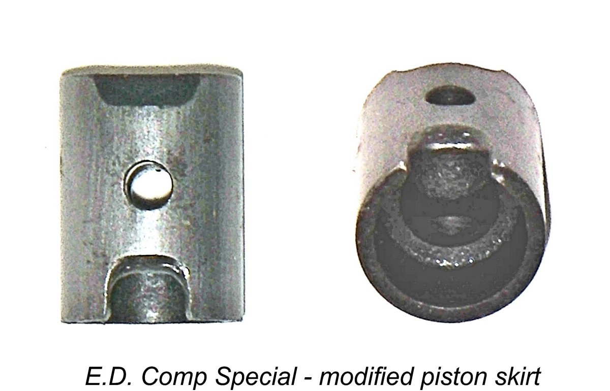 Over the years I’ve encountered several of these engines which have been modified with a view towards improving gas flow from the crankcase into the lower entry port which feeds the transfer passage. These include the previously-mentioned Type 7 example of the Mk. II no. M 1144/7 which was fitted with a Type 5 cylinder with the piston port set-up. In this example, the piston skirt port had been enlarged downward to produce earlier complete opening of the lower bypass entry.
 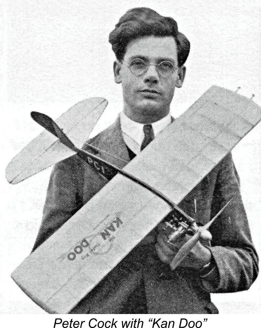 Overall, these results strongly suggest that E.D. would have done well to investigate the glaringly obvious residual design flaw of the gas flow restriction represented by the guillotine effect of the piston skirt upon gas access to the bypass at bottom dead centre. It’s really rather astonishing that they seem to have completely missed this avenue of potential improvement!
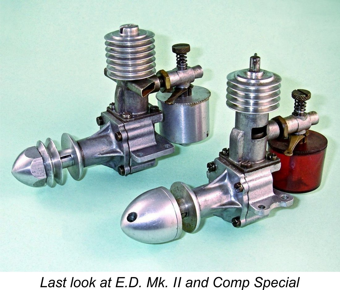
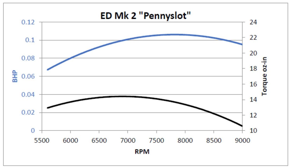
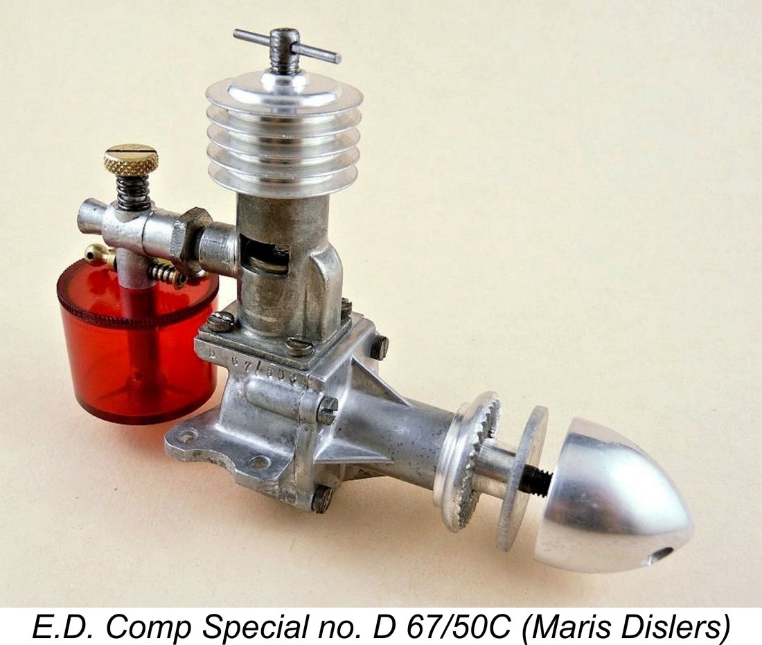
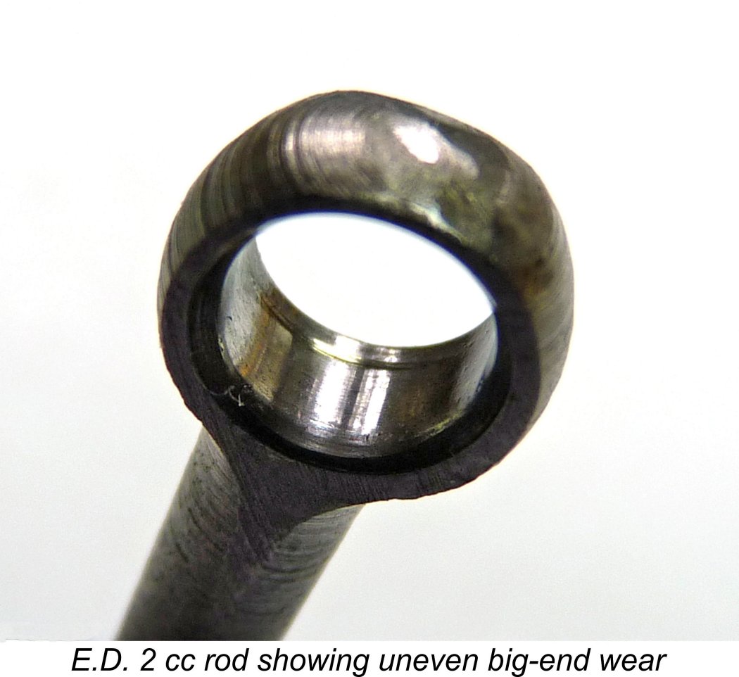 A close look at all Maris's crankpins together with micrometer checks sorted out the most worn components. Checks of conrod big ends were also undertaken to assess their condition. Scores are easy to spot. Big end bearing wear is less visually obvious, but the tell-tale to look for is a "step" at the rear where the part not in contact with the crankpin retains its original dimension, while the rest wears upwards by as much as 0.5 mm. Maris's accompanying image shows this clearly. A reasonably good pairing of crankpin and conrod can restore a so-so engine to good performance. Maris found that combining his good Comp Special top end with a Mk. II bottom end having an acceptable crankpin/conrod combination changed things completely and gave excellent performance right up to the expected level.
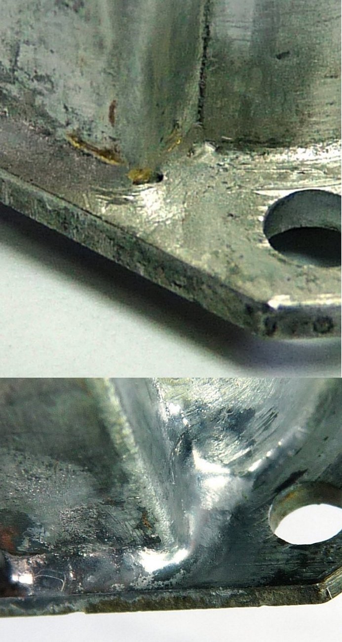 Maris has also drawn attention to the best approach to dealing with such issues as repairing the sweat-soldered joints on an E.D. "stovepipe" cylinder. Aside from Mk. II exhaust stacks coming off, he's more than once seen cracks develop between the base of the bypass cover and the cylinder flange or even the cylinder itself. In the case of a recently-purchased E.D. Mk. III, a previous owner had clearly had a go at repairing such a crack using a soldering iron, but had left an unsealed opening near the corner, creating a serious crankcase leak.
 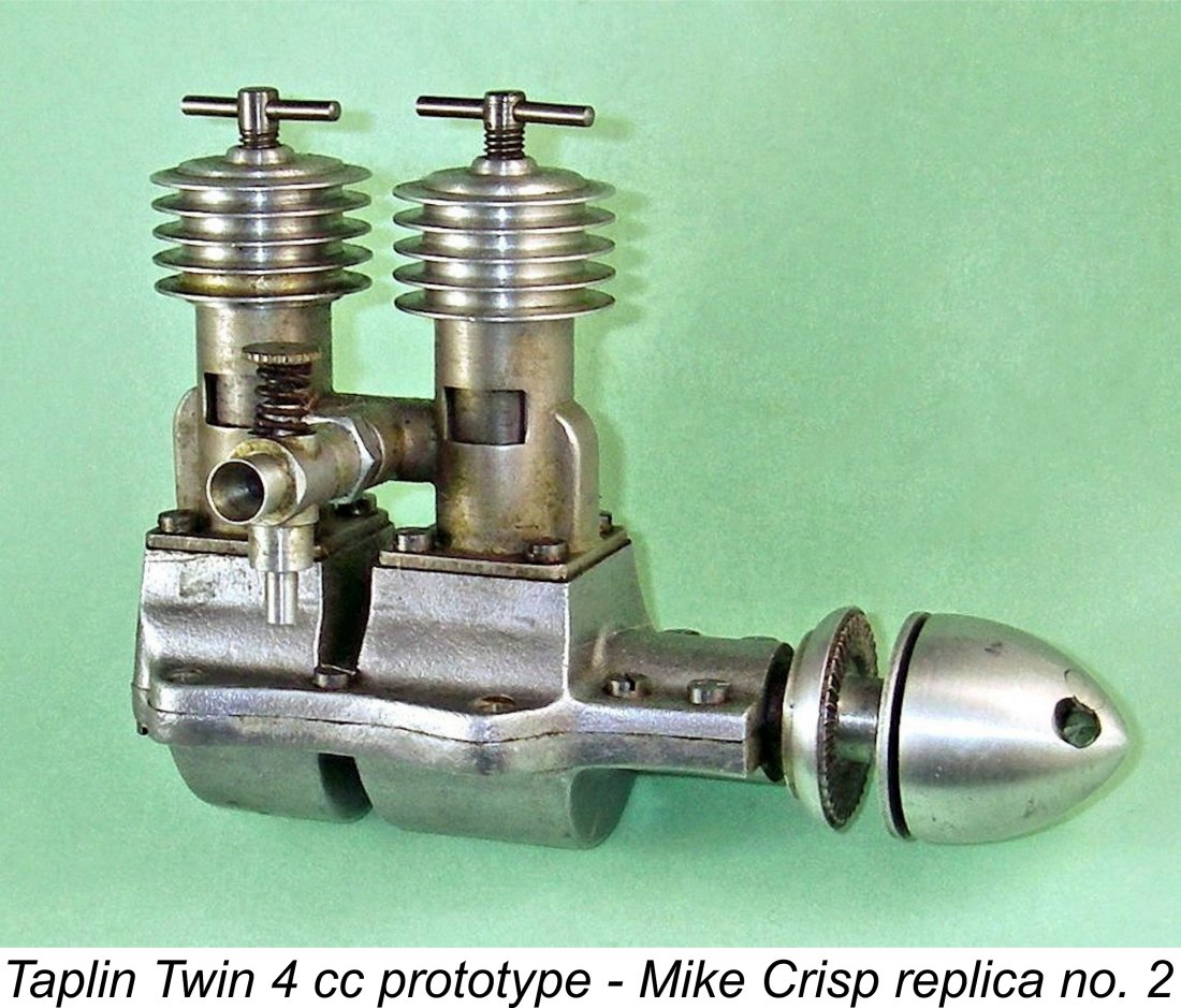 During the early 1950's, Col. Taplin's attention was drawn to the possibility of creating a sideport induction in-line twin-cylinder diesel engine of relatively simple construction. A few diesel twins had already appeared from makers such as
 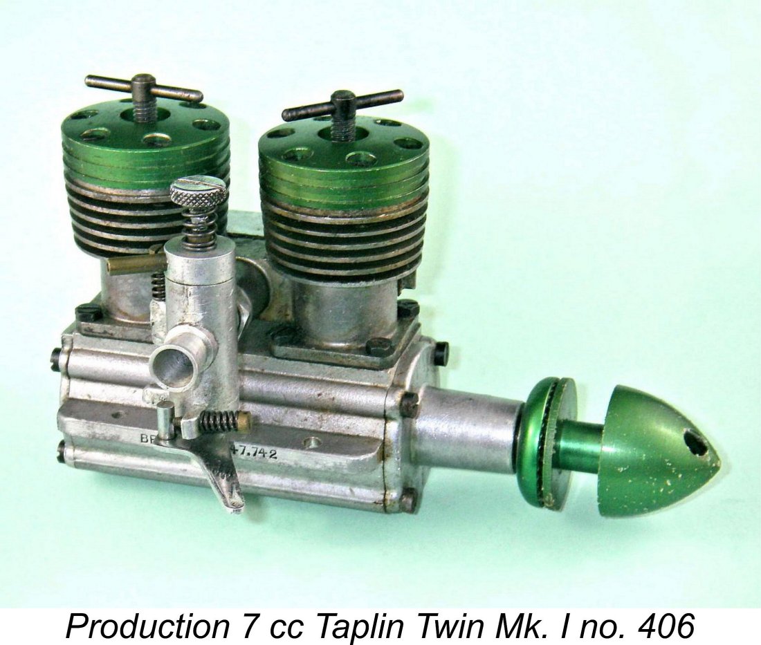 Although only a couple of examples of the original 4 cc Taplin Twin prototype survived over the years, it was possible for Model Engine World (MEW) Editor John Goodall of Barton Model Products (BMP) to have his friend and fellow enthusist Mike Noakes create a set of permanent molds to produce accurate replica crankcase castings for the 4 cc variant. The resulting castings were made available to home constructors through BMP, resulting in the creation of a number of fine replicas around the world.
 | |