
|
|
Oriental Enigma - the Sky Shark 49
My initial study of this engine and its background led to the February 2009 publication of the original version of this article on the late Ron Chernich’s “Model Engine News” (MEN) website. So why the article’s re-publication here? Mainly because my mate Ron left us in early 2014 without sharing the access codes for his heavily-encrypted site. Because no maintenance has since been possible, the MEN site is slowly but perceptibly deteriorating as the various links fail progressively - an inevitable process which can have only one ending in the long run. Since it still appears to be the only published source of information in English on the Sky Shark, I was unwilling to risk the loss of reader access to the information, hence the article’s re-publication here. The Sky Shark 49 was manufactured in Japan during the early 1950's at a time when the products of the emerging Japanese model engine manufacturing industry had yet to attract any real notice from the English-language modelling media. Indeed, at this time Japanese engines were rarely seen outside their country of origin apart from those which were brought back from Japan by members of the post-war occupation forces. It was not until the mid-1950's that the penetration of international markets by Japanese model engine manufacturers reached the point at which their products began to attract widespread media attention. In any case the Sky Shark was never among the models which were marketed outside Japan.
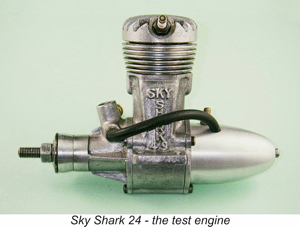
Fortunately, I’m able to make some progress in bringing this hitherto obscure motor out into the light of day thanks to the fact that I've managed to acquire several examples of the engine, one of which is an as-new example complete with box. These are the only two examples of this engine that I've ever seen in the metal, although I'm aware of the existence of a few other examples. My LN boxed example is missing its instruction sheet and display insert (if they ever existed) and the box itself gives no information regarding the manufacturers. The other example has had a fair amount of previous use and has been somewhat butchered in the mounting area but is in excellent condition in all other respects apart from missing its original needle valve and tank. It thus affords a perfect opportunity to test the running qualities of the design. Hence I’m in a unique position to review the engine in great detail on the basis of a first-hand in-depth evaluation. But before doing so, I'll share what I've been able to learn about the Sky Shark from sources in Japan. Even in that country the engine is little-known and very rare, but it has been possible to piece together the general outline of the story. Before getting started, I wish to acknowledge the invaluable assistance rendered to me by Alan Strutt of England. Alan was most generous in providing photographs from his own collection as well as information regarding Japanese model engine manufacturing during the early post-war period. A healthy share of the credit for this article is thus due to Alan rather than to myself. Origins
It may seem surprising to some that a new commercial model engine manufacturing enterprise could rise so rapidly quite literally out of the ashes of WW2. The widely-unappreciated reality is that power modelling had been very popular in Japan prior to that conflict, creating a pre-war demand for model engines which could not be filled from outside sources due to import restrictions and other factors. Hence home-grown engine manufacturing operations such as O.S. (among others) were established quite early on to serve this market - Shigeo Ogawa of O.S. fame sold his first engine in 1936 and was well-established by the time of Japan's entry into WW2 in late 1941, even managing to sell a few engines in the USA prior to that unhappy event. However, model-related activities in Japan were invisible to modellers in the rest of the world at the time due to language and political barriers. Consequently, the extent to which power modelling and model engine manufacturing had take root in Japan prior to WW2 has never been fully appreciated elsewhere. Naturally, those pre-war Japanese power modellers who survived the war were very keen to resume their peace-time hobby. Some of the more talented craftsmen among them began to make their own engines (as some of them had done prior to and during the war), and a few of these individuals elected to join Shigeo Ogawa in attempting to make a living from their interests, Mr. Haruyama being among them.
The other factor which needs to be recalled in order to understand the phenomenal growth of the Japanese model engine manufacturing industry immediately after the war was the concurrent arrival in Japan of the predominantly American army of occupation, a massive force of almost 500,000 service personnel which naturally included a significant number of individuals who were modellers in their free time. These individuals had money to spend, unlike many of the citizens of war-ravaged Japan. Japanese artisans in a wide range of fields were quick to take advantage of the opportunities presented by this situation.
The very rare early Haruyama and Haru offerings were quite interesting if somewhat imitative designs, evidently owing much to the earlier Atom and M&M engines from the USA. Presumably someone had There was also a very interesting "dummy" twin cylinder model which foreshadowed several genuine multis produced later by Mr. Haruyama. In this apparent twin, one of the cylinders was a dummy made of aluminium which served as a fuel tank, while the other was a conventional working cylinder. Like the similarly-arranged Premier Lionheart “dummy twin” from England, this was presumably intended for scale model aircraft. A .24 cuin. Haru model featuring conventional cross-flow loop scavenging was also produced in both ignition and glow-plug forms. Many of these early Haru productions were identified by a simple H cartouche, although some carried no identification at all.
It's worth noting at this point that from a production standpoint the Sky Shark represents something of a side-step from both the preceding and following Haru lines. Prior to becoming involved with the Sky Shark, Mr. Haruyama had tended to produce engines in this general displacement category which featured elegantly stylized and polished crankcases with three-bolt front housings (as in the Sky Shark) and rather individualistic intake and bypass designs. The Sky Shark retains many of the engineering design features of the other Haruyama designs but is presented in a very different style with its heavy and rather ungainly castings. It appears that it may have been motivated by a desire to reduce production costs by minimising the finishing effort involved, or may perhaps have been the product of a partnership with others in which Haruyama acted in effect as the design consultant. We'll probably never know. However and for whatever reason it came about, the name of the revised design was changed from Haru 49 to Sky Shark 49. All examples of the Sky Shark were reportedly manufactured between 1952 and 1954. They seem to have been produced in very small quantities - well-informed contacts in Japan were able to report only two other known examples apart from my own pair, and neither of them were apparently complete. A small workshop-scale production facility is implied here. Having set the scene as best I can, it’s time to take a closer look at this engine. Description
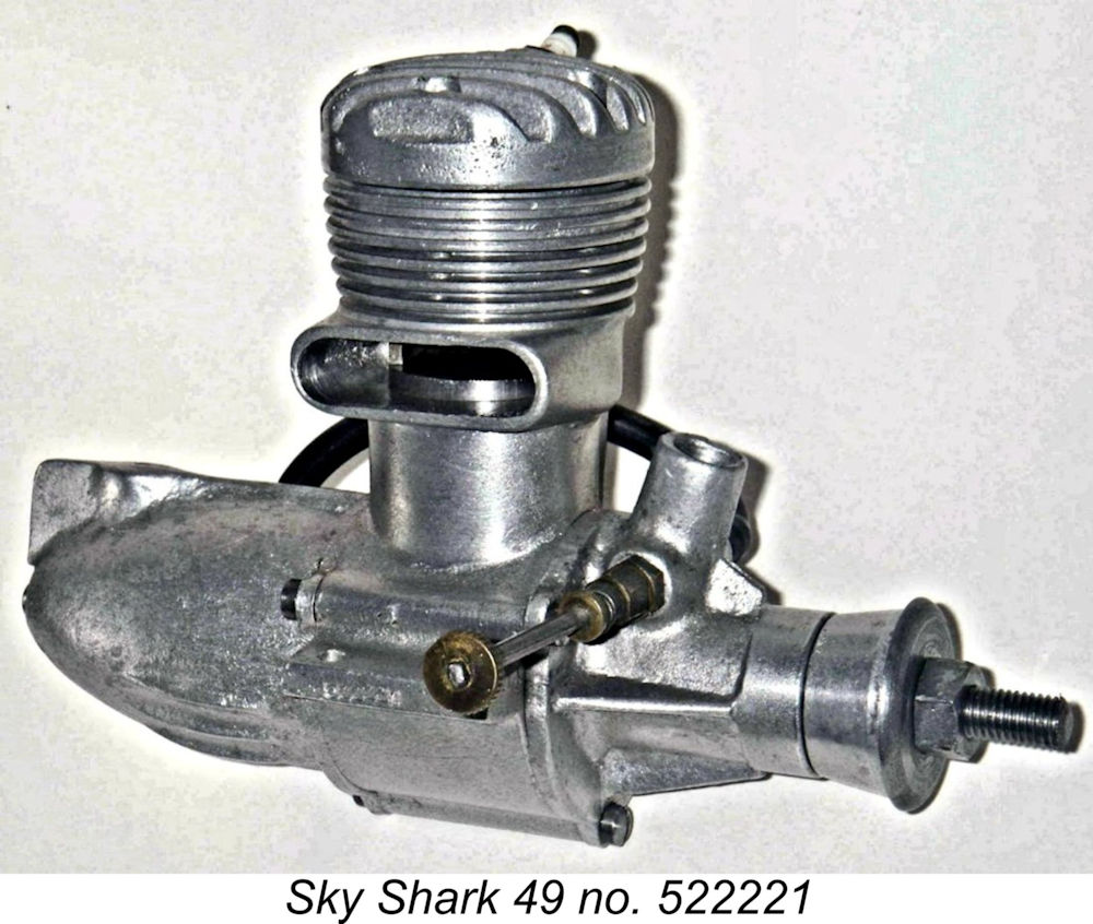
At first sight, the Sky Shark 49 looks like a more or less conventional Japanese crankshaft front rotary valve (FRV) loop scavenged glow motor of the early 1950's, albeit rather massively constructed and somewhat less sophisticated than some of its competitors in terms of its design and finish. Overall, it has rather a "home-made" appearance. Pretty much all of the externally visible major components - crankcase, front bearing housing, cylinder head, backplate and tank - are based on relatively bulky sand-castings which are left in more or less their "natural" state apart from what appears to be some superficial hand cleanup For a plain bearing glow-plug motor of .49 cuin. displacement, the engine is a bit of a lump, weighing in at a hefty 11.875 ounces (337 gm) complete with tank, plug and fuel tubing. The massive sand-cast tank and its long retaining screw together account for over 1 ounce of this, but the weight of the engine minus tank is still pretty substantial. There's no doubt about the engine's identity - the name Sky Shark 49 is boldly cast in relief onto the bypass passage on the left side of the crankcase. The bypass passage is relatively small for an engine of this displacement.
Another highly distinctive visible feature is the disposition of the assembly screws. The use of five asymetrically-disposed screws to secure the cylinder head is a most individualistic approach and one which I personally can't recall having encountered previously. The asymetric disposition of these five screws ensures that the head can only be installed in its correct orientation relative to the rest of the engine The use of only three screws to retain the front bearing housing is also worthy of comment. This number of screws appears to be rather marginal for an engine of this displacement and torque output, especially given the fact that they're relatively short M3x0.6 slot-head items. The backplate is also retained by three similar screws.
The Sky Shark tank sports a ridge along the top which terminates in a prominent fin at the rear. This is at least visually in keeping with the engine's name ...........perhaps that was the intention! The ridge incorporates a single small vent hole with no separate filler hole, leading one to assume that the tank was intended to be filled by withdrawing the fuel line from the tank and filling through the fuel line hole. This is of course a perfectly straightforward procedure. The prop driver on what I believe to be the earlier of my two examples locks to the crankshaft in the conventional manner using a taper at the front of the shaft which matches a tapered recess in the rear of the prop driver. This has the advantage of ensuring good alignment and strength while at the same time allowing for some potential slippage in the event of a hard crash. The apparently later boxed example differs in having a single flat milled into a protruding shoulder on the front of the shaft rather than a taper. The driver of this example is broached to match the flat on the shaft. In both cases, the knurling of the driving face appears to be stamped. The driver on the keyed example is a The airscrew mounting system is somewhat atypical of larger Japanese engines of this period, consisting of a 6 mm stud which threads into a tapped hole at the front of the crankshaft. This allows the exposed length of thread to be adjusted to suit the prop being used, also protecting the shaft against breakage in a hard crash - in most cases, the stud will bend as opposed to the shaft bending or breaking. Somewhat oddly, the only other Japanese designs to use this arrangement at the time were the Enya .63 and .60 cuin. Typhoon models. In the case of the Sky Shark, the replacement of a bent stud is of course a very simple matter which is greatly preferable to the replacement of the entire shaft! The prop is retained by a standard 6 mm nut with a sturdy steel washer.
The boxed engine has the serial number 522221 stamped on the outer edge of the right-hand mounting lug. There seems to be no possibility whatsoever that this is a number in a straight sequence (over half a million units?!?), so it's likely that the number somehow indicates the date of manufacture and the production batch. Since we're reduced to grasping at straws here in any case, we might postulate that the first three digits may indicate a date of February, 1952, which is within the range of dates reported by my Japanese informants. The final three numbers could indicate that the engine was completed on February 22nd and was the first engine finished that day. Alternatively, they could imply that this was the 221st engine completed up to that point. It's impossible to be certain in the present absence of additional serial numbers. The second of my two examples had a serial number in the same location, but this has been almost completely eliminated by the filing of the outer ends of the mounting lugs, presumably to make the engine fit a specific model. Traces of three digits are still visible, but there's not enough left for any actual numbers to be derived. The mounting holes on this example have also been enlarged. Sigh..........
The box is a sturdy cardboard item with a plain label giving the name of the engine and nothing more. The fact that the engine is named in English seems to imply that the English-speaking market was a primary target for these engines. If there was ever an insert, it is now missing. The same goes for the instruction sheet. The 2011 eBay listing of that second NIB example also did not include either an insert or a leaflet, making it appear possible that these were never provided. A rough check on the timing of the engine gives the following nominal measurements:
The relatively short induction period is further constrained by the fact that we are dealing with a round induction port in the shaft engaging with a round intake venturi. This combination results in an induction system which is fully open for considerably less than the 150 degrees shown above. The fact that the induction tube has a diameter of only 8 mm for the 4.5 mm spraybar is a further indicator of a relatively constricted induction system for an engine of this displacement. The rather conservative transfer period is further compromised by the relatively small bypass passage mentioned earlier. All of these factors suggest an engine that was designed for lower-than-usual operating speeds by normal glow-plug standards. So much for what can be learned from an external examination of the Sky Shark. To learn more, we have to dismantle the engine. I was initially reluctant to dissect the boxed example given the engine's condition and rarity, but there were indications in the form of slight marks on some of the screw heads that someone with The first step is the removal of the tank from the LNIB example. Here we find that this particular engine had its tank secured by a 4-40 screw - most unlikely for an early 1950's Japanese engine! The mystery is solved when we discover that a previous (and presumably American) owner clearly lost the original 3x0.6 metric screw and thankfully resisted the temptation to re-tap the original thread in the backplate boss. Instead, he filled the hole with JB Weld or equivalent and threaded the 4-40 screw into that material. Being somewhat larger, the original thread was preserved essentially undamaged and the hole was easily cleaned out to its original specification. I made a new screw of the correct thread, and happiness was restored. Next, it's off with the backplate. Most Japanese engines of this vintage employed a plain annular paper gasket without "ears" for the hold-down screws. My less complete example features such gaskets, but they are missing on the boxed engine. It's likely that such gaskets were originally used on all examples but have been lost in this case during previous dismantling operations. The absence of the gaskets appears to be inconsequential in any event - base compression is very good in both examples. This is a tribute to the standard of machining.
Here we notice the first of a number of significant differences in the detail design of these two examples of this engine - the crankwebs are of entirely different configurations. That in the LNIB example is of the full disc pattern with counterbalance as seen at the left, while the less complete example features a crankweb which is cut away on both sides of the crankpin to remove material on that side while retaining the counterbalance on the opposite side. The consequence in practical terms is that the less-complete example is considerably more heavily counterbalanced. At first sight, this has the appearance of a design response to a vibration problem and might be taken to suggest that the engine with the cut-away crankweb was the later variant. However, it's a fact that the majority of early Japanese engines employed crankshafts with cut-away crankwebs. When we take into account that the later Haruyama designs (of which more below) used full-disc crankwebs, it becomes apparent that the incomplete engine with the cut-away crankweb is almost certainly the earlier. And there's more evidence to support this conclusion, as we shall see. Removal of the backplate also allows us to discover that the backplate of the boxed tank-equipped example features a pin-hole which communicates with the crankcase interior from the base of the tapped tank mounting boss. With the tank in place, this is effectively blocked by the tank mounting screw. Operation minus the tank would require that the tank mounting boss be sealed by a short 3 mm screw to maintain crankcase compression. It might appear initially that this feature was intended to allow for the provision of pressure fuel feed, although why one would seek to do this for an engine of such modest design pretensions is a bit of a puzzle. However, the other (incomplete) example has no such pin-hole in its backplate. For this reason, I suspect that the presence of this pin-hole in the one example simply represents the pilot drill for the tank mounting boss being unintentionally taken fractionally too deep and breaking through at the tip. The makers elected not to discard the component, knowing that the tank bolt would plug the hole and re-establish an adequate seal. If this scenario is true, as I think likely, then it certainly confirms the general impression that the engine was largely "hand-made" and that the manufacturer could not afford to "waste" castings.
The incomplete example features a conventional system based upon the use of a thin vulcanized asbestos gasket like those in contemporary use on engines such as the K&B models. The top of the uppermost cylinder flange is perfectly flat, as is the base of the cylinder head. Unusually, the head is not keyed into the upper cylinder in any way - it's held in its correct lateral position solely by the five hold-down screws. This system seems vulnerable to blow-out under pressure because the gasket is not recessed and hence is not supported at its outer circumference, being located during assembly solely by the five cylinder head hold-down screws bearing upon its outer edge. However, the arrangement appears adequate for this low-compression design. The boxed example is far more interesting! In this instance, there's no gasket at all. Instead, the underside of the head features a V-section circumferential groove machined around the sealing area which locates onto a protruding annular "wedge" of matching form machined into the top of the cylinder liner. This is a very intelligent arrangement since the head is securely keyed into position on the top of the cylinder, allowing the two components to be lapped together. When the head is tightened down, the raised annular protrusion will wedge itself very tightly into the groove in the cylinder head, creating a highly effective seal on both faces of the "wedge" without any need for a gasket. In practise, compression seal on both of my examples of this engine is outstanding.
We can now visually confirm that the piston crown in both examples is equipped with a curved baffle formed by turning with the piston chucked off center by the required amount. This is a good idea since it keeps the baffle closer to the cylinder wall across its full width and should impart both better direction and higher velocity to the incoming mixture. A similar approach was seen on several of the contemporary Mamiya engines as well as the previously-illustrated Haru 24 loop-scavenged model. With the engine in this state, it's a simple matter to measure the bore and stroke. Here we learn that we're dealing with a long-stroke design - the measured bore and stroke of both examples are nominally 21.0 mm and 23.0 mm respectively for a calculated displacement of 7.97 cc (.486 cu. in.). The combustion chamber is mostly formed as part of the cylinder head casting, although there is some machining involved. It is of a very simple shape, with little real attempt to generate any swirl in the combustion chamber at top dead centre. The long-reach plug enters almost horizontally on the transfer side where the element will be directly in the path of the incoming mixture. I would actually expect rather inefficient combustion to result from this arrangement - ignition will be initiated in a relatively small "pocket" of gas which is largely separated from the rest of the combustion chamber by the piston baffle at top dead centre. Quite apart from this barrier, the flame has a greater maximum distance across which to propagate than it would from a more centrally-located ignition point. The probable consequence would be a substantial delay in the full involvement of the charge in the combustion process, especially given the relatively large bore involved. This is not a cylinder head design for the higher speeds, although it would likely be very easy on the mechanical components! In fact, it seems likely that this head was especially designed to operate at lower speeds without stressing the working parts unduly - always an issue with glow-plug ignition at low speeds due to the rather limited control of ignition timing which this form of ignition embodies.
Removal of the piston assembly is the final stage in disassembly. The liner is in there "for keeps" in both examples and appears to be shrunk in, so I elected not to risk damage by disturbing the liner in either case. The gudgeon pin proves to be a hollow steel component with aluminium end pads. It has a diameter of 5 mm. Although the piston itself is milled internally to lighten, it is still a pretty hefty component. Overall, the engine gives an impression of possessing adequate strength where it's most needed, the one anomaly being the reliance on only three screws to retain the front bearing housing. An engine of this displacement really needs more. By now, one is also impressed with the quality of the engine's construction. All fits are beyond reproach, especially those that really count. The engine may look a little rough-and-ready from the outside, but internally there's little about which to complain! The one exception to the above comment relates to the tapped holes which locate the various assembly screws. Although the threads are all well cut, several of these holes in both examples are tapped very slightly off normal, suggesting that the tapping was done by hand. This is another indicator of a relatively low production rate and a high level of hands-on manufacturing being involved. I strongly suspect that this engine was the product of a small artisan workshop rather than a commercial-scale factory as such. Both engines go back together easily enough, and thankfully the job is accomplished without any adverse impacts upon either engine's present condition. Indeed, there has been an improvement in the boxed example thanks to the replacement of the tank mounting bolt with one of the correct size! And the incomplete example has acquired an accurate replica needle valve assembly copied faithfully from the original. It has also acquired a tank which, while not a faithful replica, nevertheless restores it to something approaching its original appearance. Later Developments—the Sky Queen Line
By this time, the designer had moved into the over-square camp as far as working geometry was concerned. Bore and stroke of the Sky Queen 55 were measured at 22.6 mm and 21.5 mm respectively for a calculated displacement of 8.62 cc (0.53 cu in.), which is slightly at variance with the 55 designation stamped just below the exhaust port. Like the Sky Shark, the piston has a curved deflector, a feature which was also present in the earlier Haru 24 and the The other noteworthy feature of the Sky Queen shaft is the slightly unusual shape of its induction port, which is an elongated circle of "race track" shape rather than the more common round hole or rectangular aperture. This represents an advance from the Sky Shark design in that it gives faster opening and closing than a round hole while avoiding the stress-raiser which often accompanies the use of a milled rectangular port. The later models of the Hope New 29 used a similar shape, which has much to commend it. The crankpin is hollow and the crankweb is counterbalanced, mirroring the same features which appeared in the earlier Sky Shark. The con-rod is a casting or possibly a forging, with a bushed big-end. Bearing in mind the use of slotted fasteners rather than the cross-head screws which became fashionable later, and noting that the Sky Queen has twin needles for a rudimentary form of speed control, Alan put its date of manufacture as 1957-60.
Upon comparing a number of the features of the Sky Queen and Sky Shark motors, the direct design relationship is obvious. Quite apart from the seemingly related names, points of similarity include the unusual plug location, the use of only three screws to hold the front bearing housing in place (seemingly rather inadequate for engines of this displacement), the highly individualistic use of five screws to retain the cylinder head, the crankweb design and the use of a curved piston baffle. The Sky Queen thus clearly represents a further evolution of the Sky Shark design. The Sky Shark On Test
Accordingly, I set it up in the test stand with a "hot" long-reach plug fitted. I started with a 12x6 APC prop, which I expected to suit this engine quite well. After filling the tank with some 15% nitro fuel having an elevated castor oil content, I set the needle by guesswork at 4 turns, gave it a prime and hooked up the plug. A turn to confirm that I had a "bump", and two or three flicks later it was running! Dead easy - it took longer to type this sentence than it did to start the engine! In fact, this is one of the most user-friendly large glow-plug motors of my personal acquaintance. Despite the relatively low compression ratio, the plug could be disconnected immediately with no effect on running. The engine proved to be an extremely consistent runner, four-stroking very smoothly and showing a beautiful "break" into two-stroking as I leaned it out. The replica needle valve assembly worked perfectly, providing excellent mixture control while holding its settings firmly at all times. Suction was outstanding, as you'd expect given the small venturi coupled with the very thick spraybar. There was some vibration, but this didn’t affect the needle at all. Once leaned out, the engine ran absolutely smoothly with never a trace of a misfire and absolutely no tendency to sag. It did seem to use a lot of fuel, though. There was also a higher-than-usual proportion of unburned fuel in the exhaust gases - you could both see and smell this. The impression given was that combustion was less than complete and that the engine was ingesting more fuel than it could burn. One might expect this given the rather low-tech combustion chamber configuration. The engine turned the 12x6 APC prop at a steady 8,100 rpm, appearing willing to do this all day if desired. Not that fast, but this is a lot of prop! I then ran tests on a range of props. With its relatively low compression ratio, inefficient combustion chamber with long flame propagation path, long stroke, constricted induction and bypass systems and conservative timing, you'd expect this to be an engine that showed best at the lower speeds. And that's exactly what you get, as the following results show:
As the above data show, the engine proved to be an absolutely massive torque producer! In fact, it's more like a diesel than a glow in that respect. Greatly to my surprise, it proved to be operating at or near the peak on the 12x6, which I was expecting to be on the way up - I had thought that it would peak on the 11x6 or thereabouts. As it turned out, these figures suggest a maximum output of around 0.438 BHP at 8,000 RPM. It's noteworthy that the peak is unusually flat - the engine is developing 0.400 BHP or better at all speeds between 7,300 and 9,300 RPM. A high level of flexibility is implied here. The 12x8 airscrew would appear to be an ideal load for most purposes. The figures given above for the two smallest props tested must be regarded as somewhat unreliable due to the fact that above 9,500 rpm the needle setting became hyper-critical, making an optimum setting very difficult to achieve. At 10,000 rpm it was actually impossible to find a setting on which the engine would sustain a smooth two-stroke - it either ran in irregular four-stroke/two-stroke mode or stopped dead as it was leaned out still further. The symptoms were all consistent with the engine having run past its optimum ignition timing range. With glow-plug ignition, there's only so much that one can do about that! I was using the hottest plug that I had along with 15% nitro fuel, so there was not a lot to be done about the situation. Few contemporary owners would have used that much nitro - no-one was likely to pour nitro into an engine like this! To me, this says that the rather low compression ratio and perhaps even the side-mounted plug with its long flame propagation pathway were set for a reason - the makers were actually designing for a low peaking speed with gobs of torque! If so, they did well, because that's exactly what they got! The engine runs superbly up to 9,000 rpm (well past the peak), and needles extremely well with never a trace of a misfire. The break from four to two-stroking is really beautiful - this would be an excellent stunt engine, especially given the outstanding suction that it displayed on test. A converted spark ignition user would be totally comfortable with the Sky Shark, and I suspect that the engine was designed with such users very much in mind.
As I expected, performance fell well short of the figures achieved with the correctly-matched long reach plug. I was unable to get within 600 rpm of any of the figures achieved with the long-reach plug. The engine still started just fine and ran very smoothly, but the power was definitely impacted. This seems to confirm that combustion chamber efficiency (or lack thereof) was a major factor in defining this engine's performance. And only "hot" long-reach plugs need apply! Upon re-fitting the long reach plug used originally, happiness was restored. I would expect the boxed engine with its higher compression ratio to peak at a slightly higher speed and to produce a little more power in consequence. However, I doubt that the difference would be all that great, and I would expect a somewhat higher level of vibration due to the lower counterbalance factor. Overall, a really user-friendly and sturdily-built engine that would certainly pull a large model aloft with ease as long as speed was not the primary criterion! I'd guess too that once properly run in, it would last indefinitely by model engine standards. Conclusion I hope that you've enjoyed this look at a forgotten piece of model engine history. It's amazing how after all these years there's still so much to be learned and documented! If anyone has anything further to contribute to this discussion, please get in touch. As always, all contributions will be openly and gratefully acknowledged! ________________________________ Article © Adrian C. Duncan, Coquitlam, British Columbia, Canada First published on MEN July 2010 This revised edition published here December 2024
|
||
 Here I’ll attempt to draw back the veil that has hitherto covered one of the genuine enigmas of model engine history - the Sky Shark 49 glow-plug motor from early post-WW2 Japan. This proved to be one of my more challenging engine reviews to prepare because there's hitherto been a complete absence of accessible documentary information in the English language with respect to this very rare engine. Indeed, one of my primary motivations in publishing this article in the first place was the hope that it might trigger a response from some reader who knew more than I’d been able to uncover!
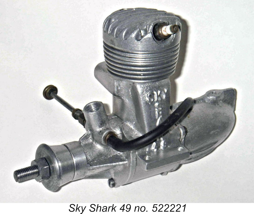 For this reason, we will look in vain for any mention of this engine in the cotemporary English-language modelling media. By the time when Japanese engines became subject to the same level of scrutiny as those from other sources, the Sky Shark was only a fading memory. Even in Japan, information appears to be thin on the ground. The engine is extremely rare today, both in Japan and elsewhere.
 The designer and manufacturer of the Sky Shark 49 was a certain Mr. N. Haruyama, who was one of Japan's earliest post-war model engine designers and manufacturers. Haruyama-san's first post-war line of model engines was marketed in Japan under his own name and later under the Haru trade name. The range was apparently introduced in 1946.
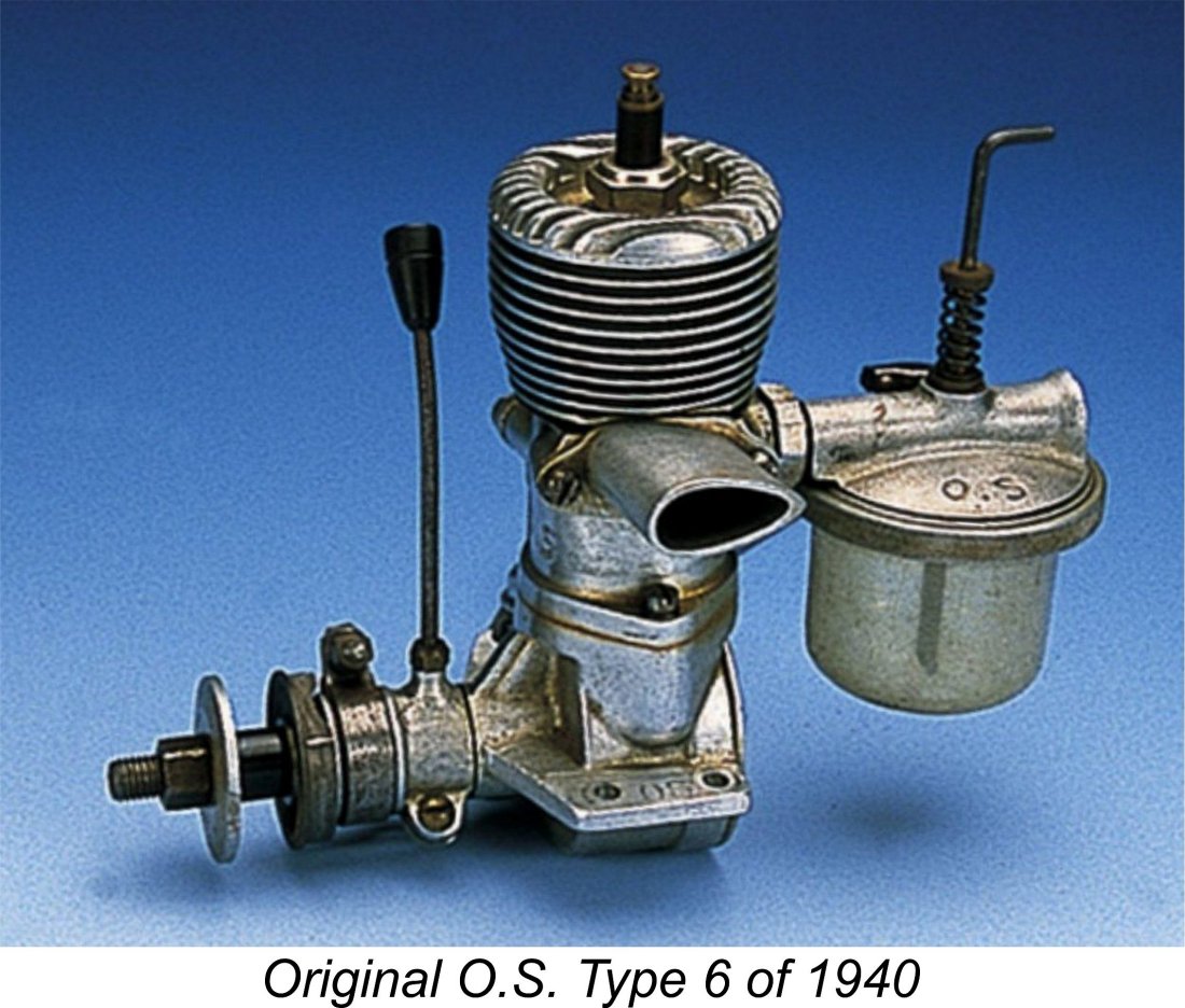 The key point to remember is that these individuals were by no means newcomers to the business of designing, making and using model engines - some of them had been doing so for years! So it was certainly not a case of a group of talented imitators jumping into a new field and learning incredibly quickly from scratch, as many people seem to assume - in fact, we're speaking about a number of experienced power modellers resuming an activity with which they were already closely familiar. This fact has been greatly under-appreciated in Western modelling circles, and it goes far towards explaining how the post-war Japanese model engine industry got off to such a fast and ultimately productive start.
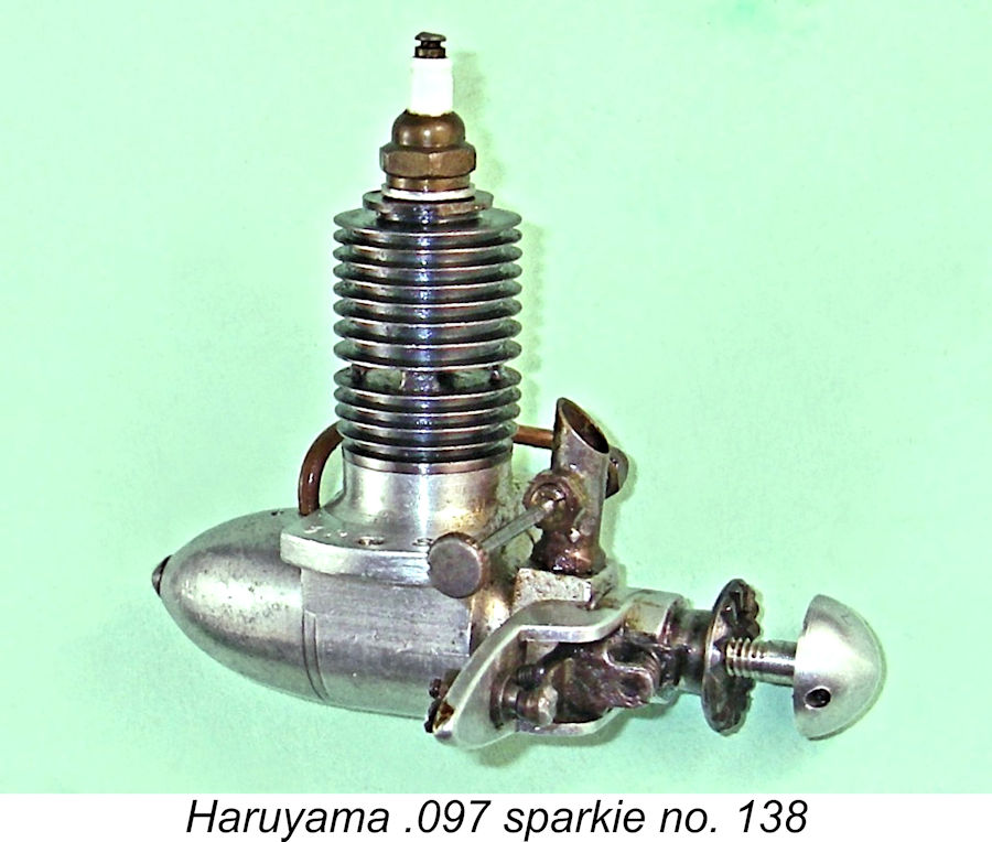 Alan Strutt recalled a conversation that he had some years ago with a former GI who arrived in Japan with the US occupation forces immediately after the war ended, quite literally when the bomb craters were still smoking! According to Alan's informant, it was possible even then to get anything mechanical made by local Japanese craftsmen, and this included model engines. All you had to do was give them a rough drawing or show them an example of an American engine, and within days the locals would be back with their own finished engine, which they would happily sell at a very reasonable price. There were lots of un-advertised locally-made engines about at the time as people struggled to survive by applying their skills to making anything that they could sell. Mr. Haruyama was among the talented individuals who set out to tap into the new post-war model engine market, initially with his Haruyama and later Haru line of model engines.
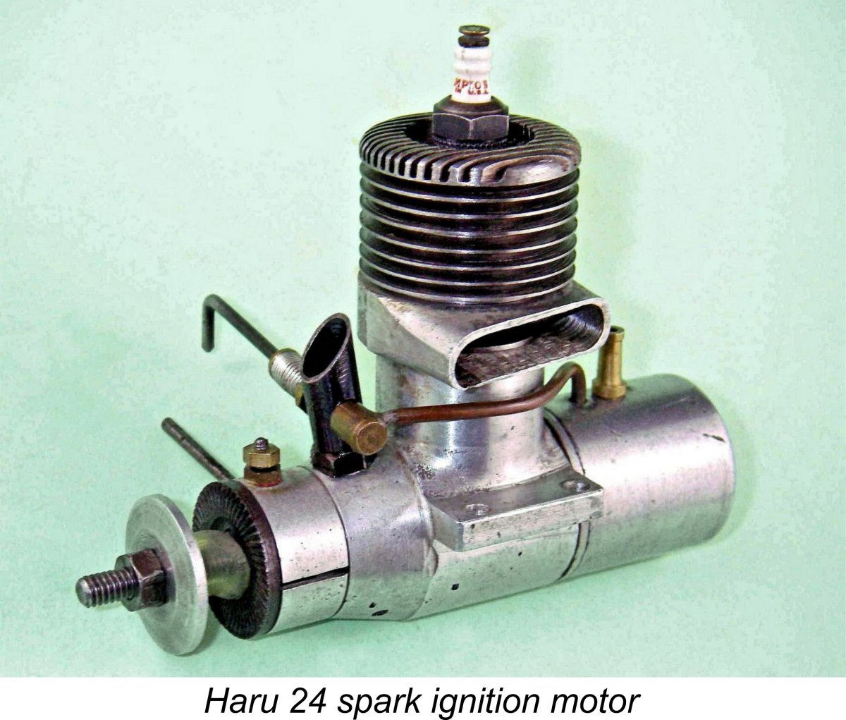 shown examples of these models to Haruyama and that was all that it took, as mentioned earlier! These original Haru models featured piston valves very similar to those used in their American predecessors. They were not alone in this - the contemporary
 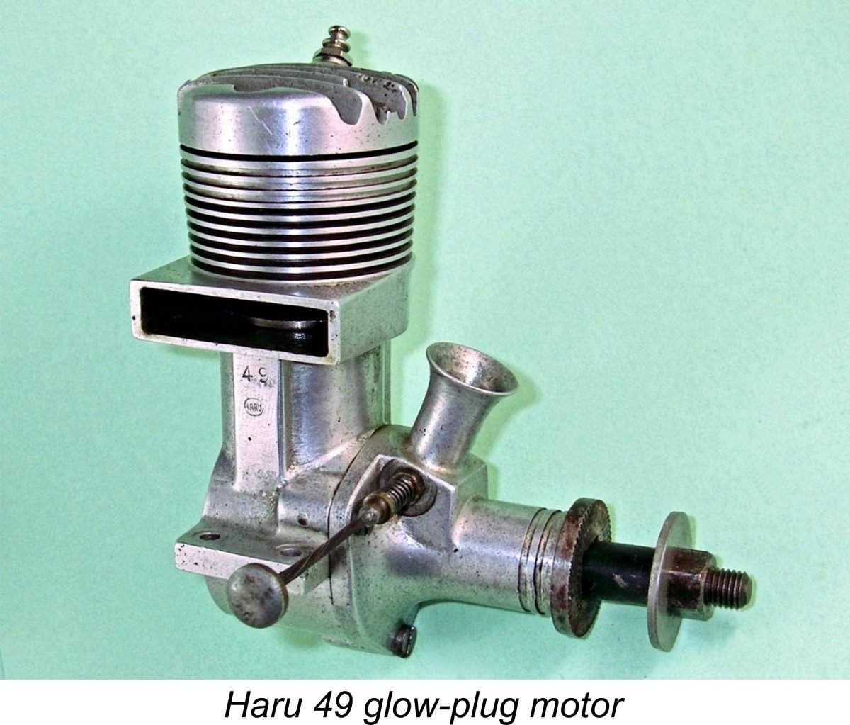 The Sky Shark 49 which is the main subject of this article represents a later stage in the evolution of the Haruyama design sequence. According to my Japanese sources, the Sky Shark 49 evolved from an earlier model called the Haru 49. This is not to be confused with the later Haru 49 illustrated here, which post-dated the Sky Shark model (see below). At present I don’t have an image of the original Haru 49, but it appears that the Sky Shark had its design basis in that earlier model.
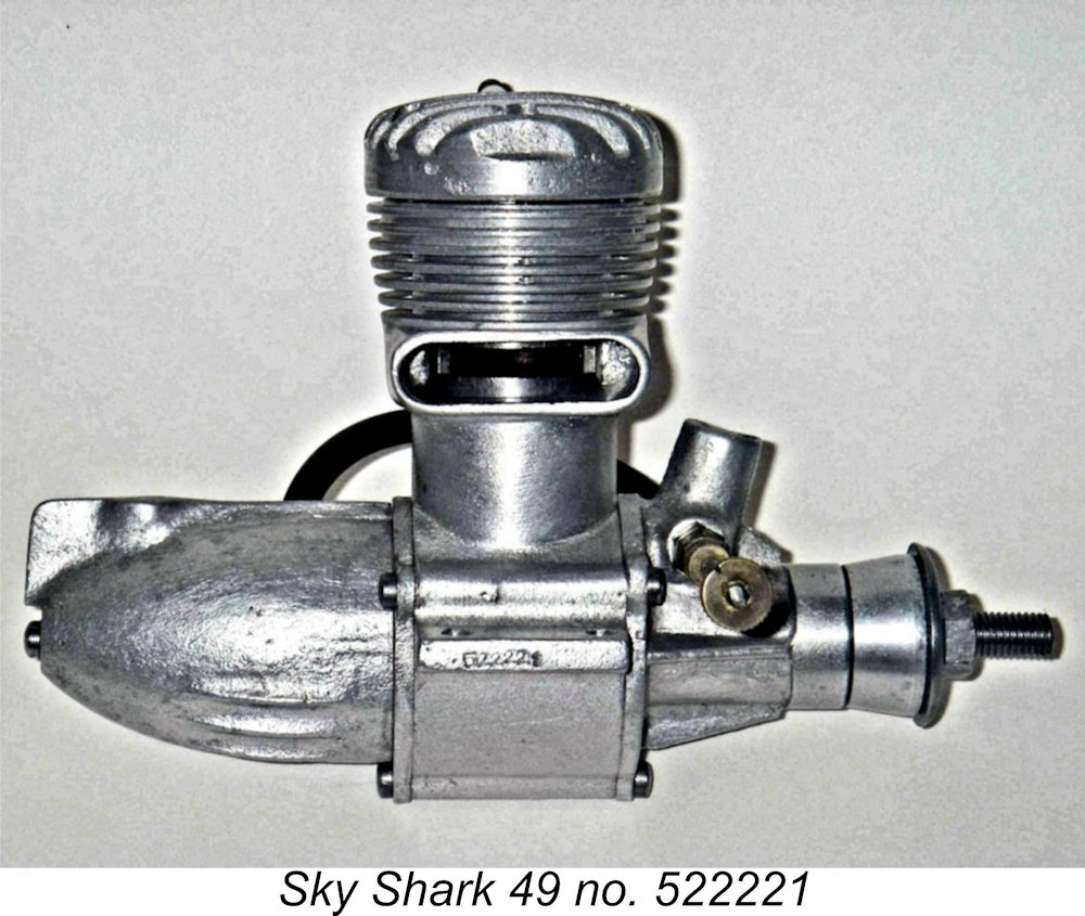 The following description is based on a detailed examination of both examples of the Sky Shark in my possession. As will be seen, the two examples differ in detail from one another, thus representing distinct variants of the engine, although they are identical in most respects. For reasons which will become apparent as we proceed, it seems almost certain that the less complete of my two examples is the earlier, and I’ll refer to it as such throughout the rest of this article. However, the two variants are sufficiently alike that all of the following comments apply to both examples except where specifically noted.
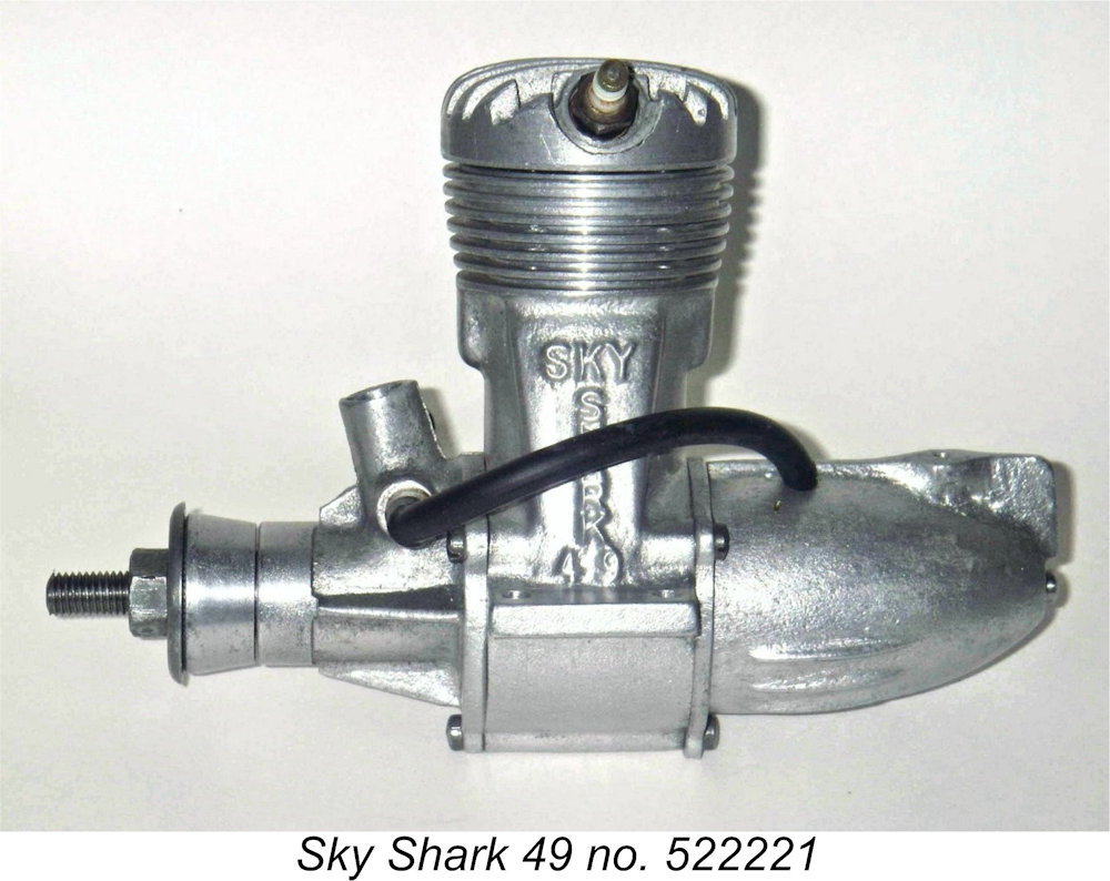 followed by a light tumbling process to impart a bit of a shine. This clean-up clearly preceded the subsequent machining operations. The original as-cast finish is visible inside the casting interiors, and it's pretty rough! All of this seems consistent with the notion that monthly production figures were not high.
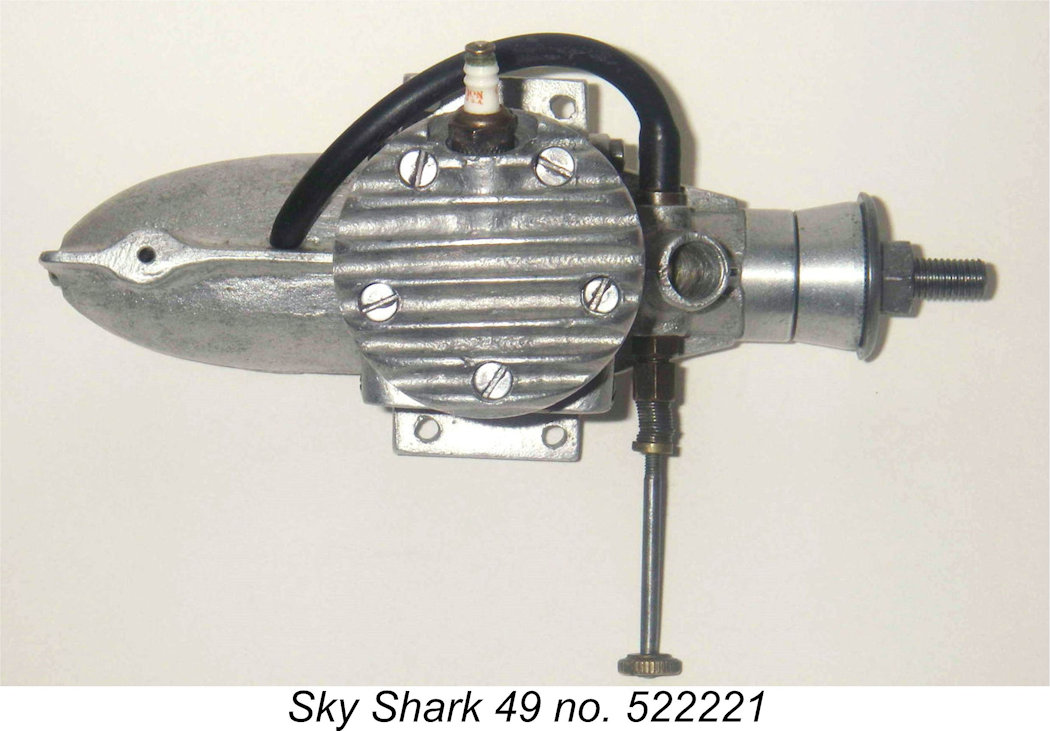 So far we seem to be dealing with a pretty standard early 'fifties Japanese glow-plug motor. However, closer examination reveals a number of quite distinctive features which set this engine apart from the rest. For one thing, the plug location is quite unusual, the plug being set on the left (transfer) side of the cylinder head in a near-horizontal orientation. This mirrors the similar arrangement employed by Duke Fox in his renowned 59 long-shaft model of a slightly earlier period.
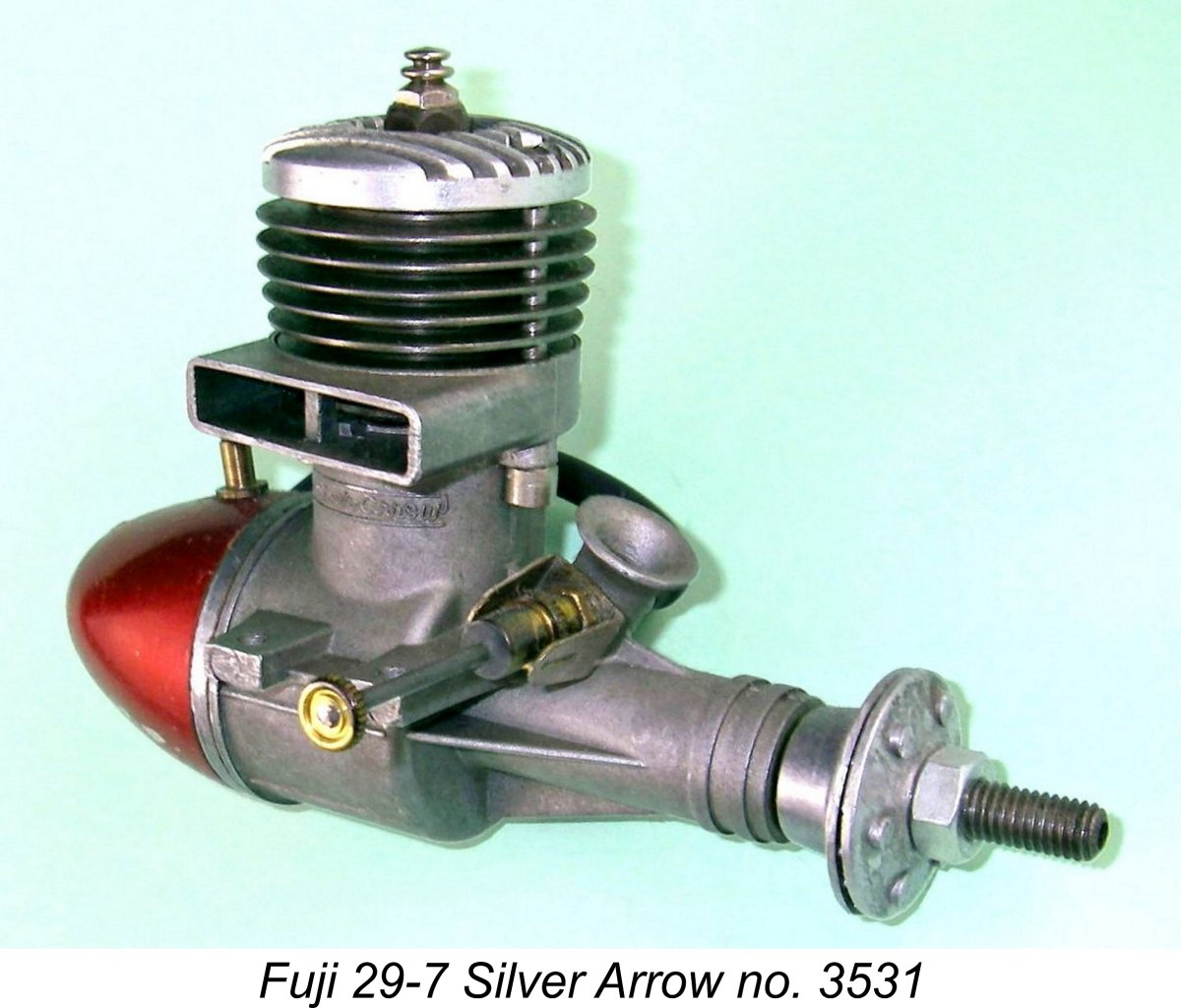 The massive and rather ungainly back tank (missing on the seemingly earlier example) is formed from a sand-casting rather than being turned, stamped or spun in the more familiar manner. It appears that the majority of Japanese model engines made before, during and immediately after WW2 used sand-cast tanks, but the continued use of such a tank as of 1952/54 was something of an anomaly even in Japan. Indeed, the use of a back tank of any sort on an engine of this displacement was rather an anachronism by that time - Fuji used a back tank on their .29 cuin.
 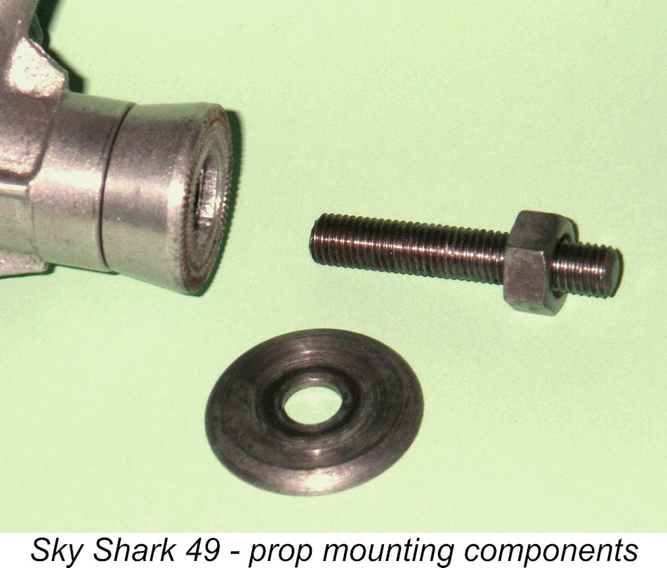 very tight fit and has to be pressed into position with the prop-nut, giving it a good level of security which is often lacking on prop drivers secured in this manner. Despite this, the taper fitting is superior in my personal opinion - the key in the alloy prop driver of engines using that system tends to wear or even strip with time.
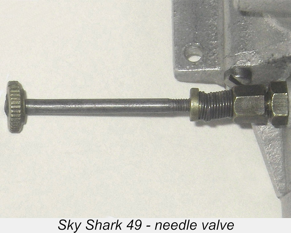 The needle valve assembly is unusually complex, being built up from no less than seven individual components! It is a bit out of the rut in that it incorporates two distinct provisions for stabilizing the needle setting while the engine is running. The externally threaded 2.5 mm steel needle screws into an internally-threaded 4.5 mm diameter brass spraybar. It is equipped with a knurled brass control knob at its outer end and a subsidiary brass disc at the mid point. The spraybar is split on the needle side at its outer end and is tensioned against the needle by means of a gland nut similar to those used on many racing engines. There is also a coil spring which is unquestionably original - both the subsidiary disc on the needle and the outer face of the gland nut are provided with shoulders to locate this spring. Indeed, the subsidiary disc serves no other purpose. The gland nut appears to be intended more to stabilize the needle in its thread than to lock it. The set-up certainly works very well indeed.
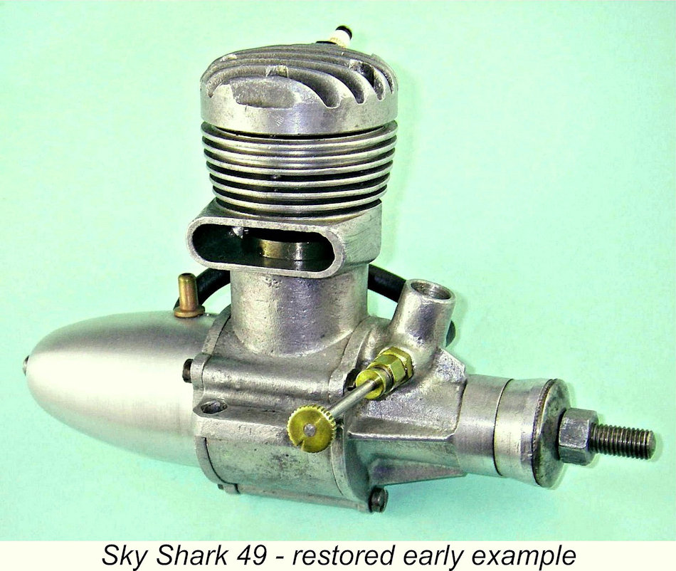 The incomplete engine in my possession was missing its original needle valve assembly as received, forcing me to make a replica using the assembly from the boxed example as my pattern. This worked out very well, since the replica needle valve is both visually and functionally identical to the original. I also made a look-alike tank for this engine. Although not an accurate replica, it does restore much of the engine's original appearance.
 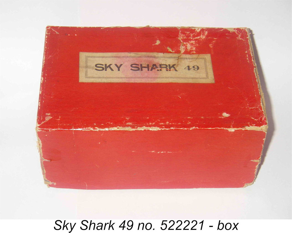 Another new-in-box example of the Sky Shark - only the second that I’ve ever seen - appeared on eBay in 2011. This one bore the serial number 522132. The fact that the first three digits are the same as mine does suggest that they relate to a production date or batch rather than a specific number of engines. If my earlier speculations regarding the serial numbers have any validity, this would be either the second engine completed on February 13
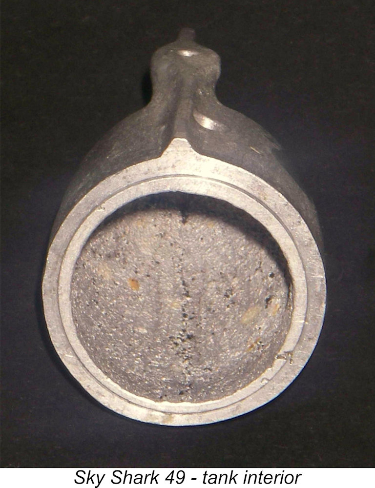 a modest helping of ham in his fists had dismantled it before me. The screws are typical early 1950's slot head items made of unhardened steel, and these are easily marred unless care is taken to use the correct screwdriver in the proper manner. With every intention of doing just that, let's proceed.............
 Onwards and inwards!! Our first look into the crankcase interior reveals a very sturdy cast alloy conrod which is bronze-bushed at the big end. The crankpin is hollow right through and the crankweb in both examples is provided with a quite substantial counterbalance weight opposite the crankpin. The interior of the crankcase is fully machined, with a circumferential channel added to provide clearance for the rod.
 Next it's the turn of the cylinder head. Here we encounter another substantial difference between the two examples available for inspection. The two engines employ entirely different approaches to the problem of maintaining a good high-pressure seal at the critical joint between the upper cylinder flange and the base of the cylinder head.
 One practical consequence of this difference is that the head of the boxed example sits rather lower on the cylinder than that of its companion. As a result, the compression ratios are different - the gasket-equipped example has a
  Now it's off with the front cover. Again we find that no gasket has been used on the boxed engine, although its companion has a gasket of the same form as the backplate. Even on the shaft with the keyed prop driver, it takes a bit of pressure to shift the driver, but once that's done the shaft is free to be removed. It proves to be mounted in a substantial bronze bushing. The crankpin has a very sturdy diameter of 7 mm and is drilled through at 4 mm diameter to lighten. The main bearing journal diameter is an equally sturdy 12 mm while the internal gas passage is only 7 mm in diameter. There appears to be no lack of strength in this component! The perfectly round induction port also has a diameter of 7 mm. It is fed by an 8 mm diameter venturi tube which is supplied with fuel by the 4.5 mm diameter spraybar described earlier.
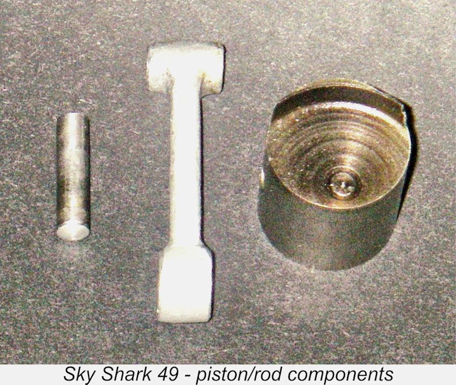 Fortunately, the fit of the piston is not unduly tight, nor is the bore greatly tapered, so it's readily possible to remove the piston assembly through the top of the liner - in fact, this must be how it was installed when new.
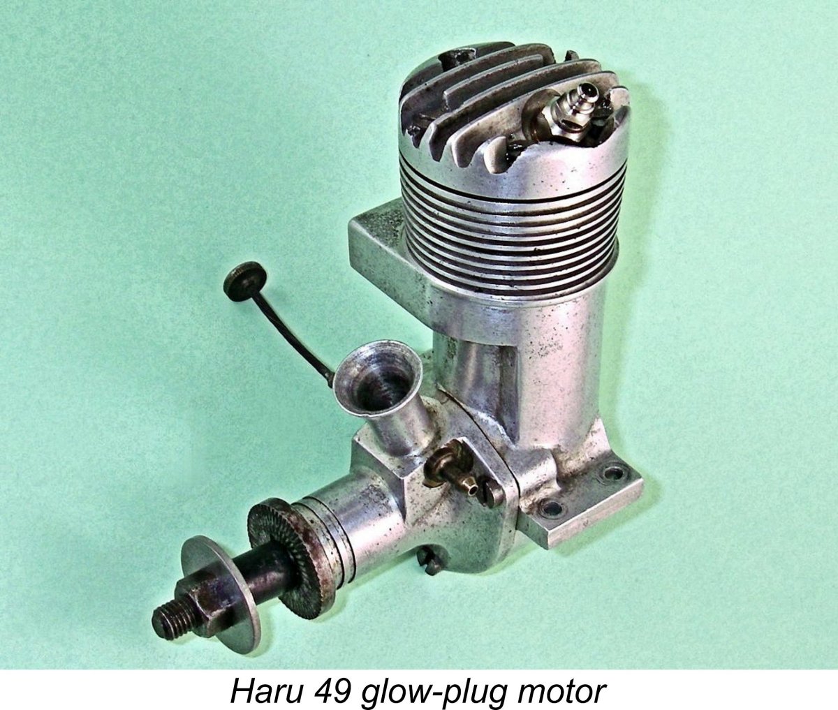 After completing the production cycle for the Sky Shark 49, Mr. Haruyama initially revived the earlier Haru marque, subsequently going on to design the almost equally obscure Sky Queen engines in both single and twin cylinder forms. Fortunately, Alan Strutt had one of the single cylinder Sky Queen 55 engines and was kind enough to take it apart for examination and measurement. The early Haru productions in the post-Sky Shark era reverted to the former H cartouche which had appeared on some of the original Haru models, but the name Sky Queen soon became attached to these later engines, presumably representing an evolution from the earlier Sky Shark name. The Haru 49 illustrated here is an example of one of these early post-Sky Shark models.
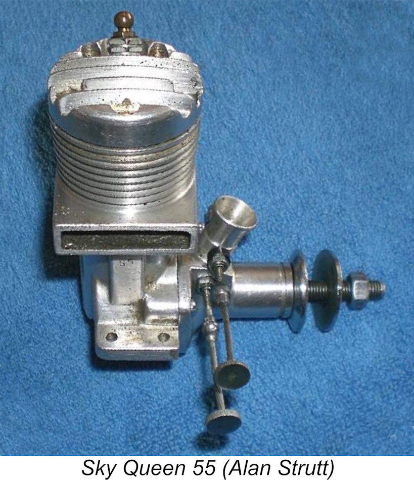
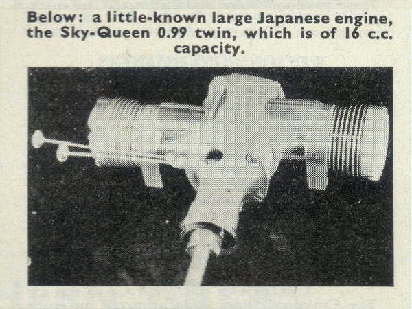 This dating appears quite credible - indeed, there is some supporting evidence in the form of a photograph which appeared in Peter Chinn's "Latest Engine News" column in the November 1960 issue of "Model Aircraft". This showed the opposed twin-cylinder Sky Queen .99 of 16 cc displacement, which also featured twin needles. This illustration appears to confirm that the Sky Queen range was still current as of 1960. However, by 1962 the range seems to have disappeared - there is no mention of any Sky Queen models in the 1962 "
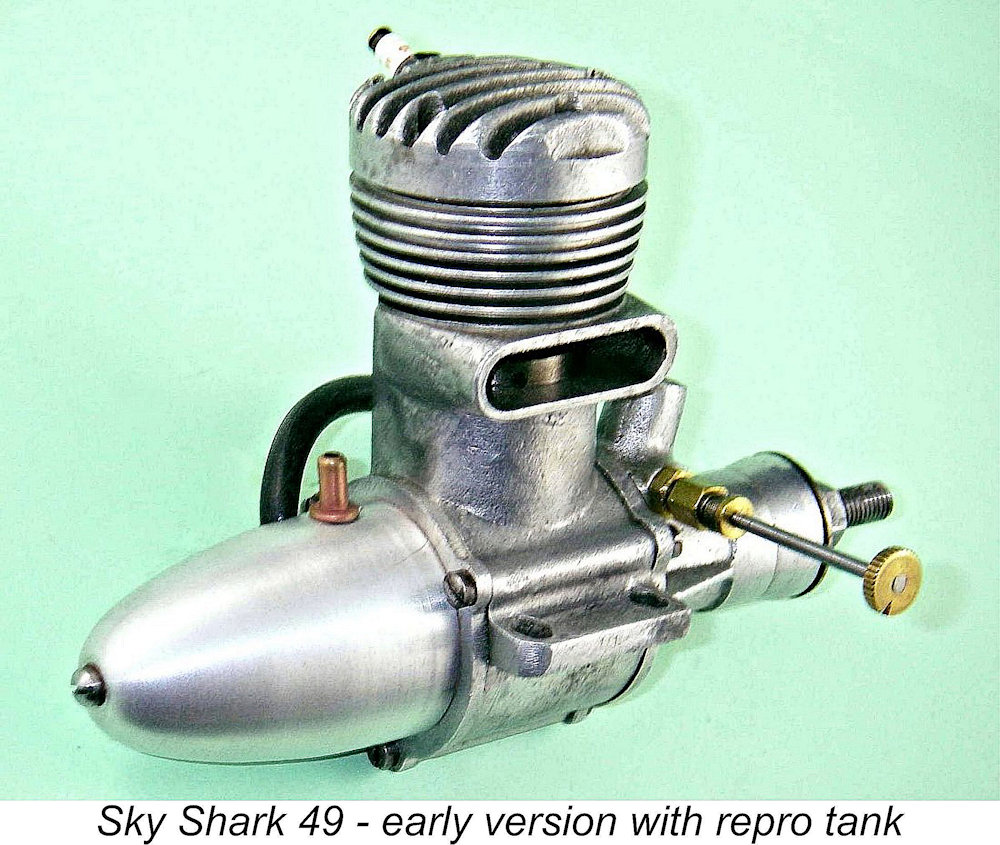 My boxed and complete example of this engine appears to be almost unused, and I was keen to keep it that way! However, the other example had clearly had quite a bit of use and had lived to tell the tale, so I felt that a little more could do no harm. It was undoubtedly well run in! The sturdy construction of the engine relieved me of any anxieties regarding possible mechanical failures during testing.
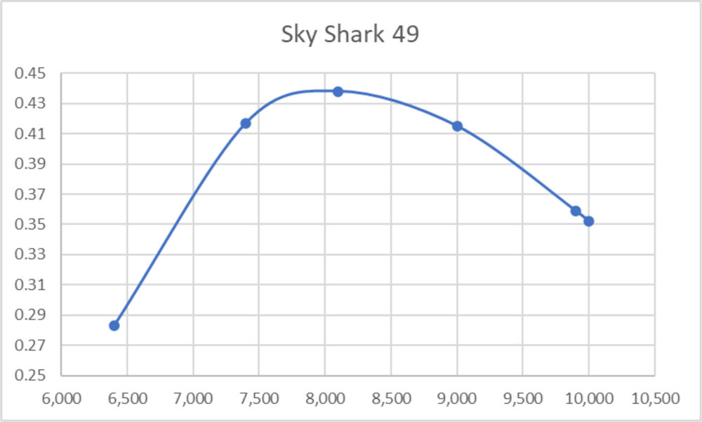
 The peak output is undeniably modest for an engine of this displacement, also being developed at very low revs by glow-plug standards. But there could have been few contemporary non-racing glow-plug engines that could match that output at those speeds! Also, the thing is shifting a lot of air on those 12 in. dia. props, believe me! If one assumes that the engine's primary purpose was large free-flight sport and scale models (as suggested by the tank style) or large C/L stunt models, it would pull a lot of airframe, albeit not all that fast.
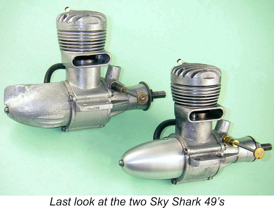 Just for fun, I tried a re-test with a short-reach plug using the same props and fuel. This would obviously have the effect of worsening an already-compromised ignition situation because the plug element would now be deeply recessed into a small side-pocket at the outer edge of the cylinder head. This side-pocket would be well out of the main gas flow and could tend to retain un-scavenged gasses from the previous power cycle. In addition, the ignition point would be even further isolated from the most distant point in the combustion chamber, thus increasing the required flame propagation pathway. A minor side effect would also be a marginal reduction in compression ratio. My intention was to determine the effect of this further reduction in combustion chamber efficiency.
| |