
|
|
The Feeney Four-Strokes
This article is basically a revised and updated edition of an earlier piece written by my late and much-missed mate Ron Chernich which appeared on Ron’s outstanding “Model Engine News” (MEN) website way back in October 2003. Unfortunately, Ron left us in 2014 without sharing the access codes to his heavily-encrypted site, leaving us with no opportunity to make corrections or additions and no possibility of carrying out any maintenance. Consequently, the now-frozen site is experiencing a detectable degree of deterioration which will doubtless continue in the future. It’s only the financial support of my good mate Maris Dislers that has kept MEN afloat so far. We all owe Maris a sincere debt of thanks! For that reason, it has seemed to me to be wise to transfer some of the more important MEN articles over to my own site, something which Ron gave me full permission to do prior to his much-regretted departure. This is one of those articles. No electronic repository is forever (including my own site), but at least in this way the material is preserved for now in multiple systems, reducing the risk of its loss. I’ve preserved all of Ron’s information in this article, including many of his illustrations. I’ve merely edited and reorganized the material to enhance clarity, also adding some updated information which has since come to light. With that having been stated, let’s get right down to it! Sources The fact that it’s possible to develop an article such as this about the Feeney engines is due mainly to the fact that the range has received a certain amount of media coverage in the past. The following references were noted by Ron Chernich when publishing his original article in 2003:
Thanks entirely to the efforts of these earlier researchers, it’s possible to unravel the Feeney story in a surprising amount of detail. Read on ……….. Creation of the Feeney Designs
By the late 1930's, Cass had established his own machine shop business, backed up by considerable experience gained through his motorcycle-related activities. It's likely that he did a good business It appears that Cass’s fondness for aeromodelling had never really left him, while his interest in engines had been stimulated by his work with motorcycles. His experience with the ‘cycles had been essentially confined to working on the four-stroke engines which then predominated, and it was probably this influence that led him in early 1938 to commence the development of a design for a four-stroke overhead valve model airplane engine. During the development stage, the sources tell us that Leja was assisted with the creation of the necessary alloy castings by Jack Feeney of Chicago. The design that emerged appeared to be worthy of production, but Leja lacked the resources required to take the design through to the production stage. Accordingly, he sold the design and manufacturing rights to Feeney, who completed the development of the engine which now bears his name, putting it into series production under the banner of his own Feeney Company. The news that this engine was under development seems to have reached the model media as early as 1938, although the production engines apparently didn’t appear until 1940. Three sizes of Feeney were manufactured, all of them naturally featuring spark ignition:
Technical Details
First, the crankshaft was machined from a casting formed in aluminium-bronze alloy. This is a material in which aluminium replaces the tin used in a conventional bronze alloy. Such alloys can have tensile strengths equal to those of medium-carbon steels, also wearing well and being highly corrosion-resistant. Their machined surfaces typically display a striking golden colour which can lead to them being mistaken for brass. The The shaft reportedly ran un-bushed in the aluminium crank case, the latter being laterally split vertically to permit assembly (think motorcycle!). The case ran "wet", being filled to a drain plug with SAE 50 oil, lubricating the two shaft bearings, cams and piston by "splash". In keeping with common four-stroke practice, the case was fitted with a breather tube (that's the thing that looks like a police whistle poking up from the camshaft housing behind the valve push rods in several of the accompanying images).
The cylinder head, valve guides, inlet and exhaust openings, cooling fins and cylinder bore were all sand-cast in one piece with rather complicated coring. No valve cages were employed (more gloom!). The inlet and exhaust valves were also machined from aluminium-bronze castings (illustrated earlier) and seated directly on the aluminium head. The rocker arms, again aluminium-bronze castings, were of conventional design. It appears that rather than the use of inserted bronze bushings, moving parts were made from aluminium-bronze in the hope that they'd serve as their own bushings. Lubrication of the rockers was accomplished by hand-dabbing a drop of oil on the shaft between runs.
The cam drive was accomplished using two spiral-cut gears. The smaller of these was fitted to the rear extension of the crankshaft; the other (at right angles to the shaft) was cunningly used to hold together the two cam segments, which
The tank was secured to a frame which in turn was attached with a screw to the top of the cylinder, placing it close to the level of the carburettor. This latter component was a rather rudimentary "reverse butterfly" design: instead of a thin shaft carrying a flat butterfly plate, a thick barrel had a slot cut in one end which could be According to one observer who visited the Feeney factory in 1940 or 1941, the engines were made to fire using an electric drill shoved over a splined driver on an engine-mounted flywheel. The jet tube was raised, lowered and rotated until the engine ran unassisted. The jet was then crimped in place. Unsurprisingly, the article author was unable to get his example to start at home by hand-flipping the prop. Factory instructions wisely stated that "…..to move the gas tank to another position or to fit a larger one, be sure to have the gas levels in the same relative vertical position as the standard tank." In other words, the engine had extremely marginal suction and any significant change in the hydraulic head of the fuel would be fatal to performance. Two different rod styles were used in the Feeney. As the crankshaft was of the "full" variety with integral crank-discs on both sides of the crankpin, both rod styles required split big-ends with removable end-caps to allow them to be fitted to the crankpin. One rod was quite conventional, being machined from (what else?) an aluminium-bronze casting and requiring no special comment. An illustration of such a casting appears below in its place.
The result was a rod of which the working length could be varied. The idea was probably to permit the compression ratio to be adjusted by extending/shortening the rod length half a turn at a time. The problem was that having the axes of the two rod bearings even slightly out of line shoves operating friction and wear rates through the roof. The absence of any locking ring or nut would seem to In my opinion, the engine's mounting arrangements left something to be desired. The Feeney was radially mounted using the same four bolts that held the two crankcase halves together. Given the presence of the camshaft housing, pushrods and timer, this required the removal of the majority of the mounting bulkhead inside the pitch circle of the mounting bolts. It also appears to have considerable potential for constraining access to the timer when the engine was mounted in a model. The use of beam mounting would have been greatly preferable. Advertising for the Feeney series began appearing sporadically in “Air Trails” and “Model Airplane News” (MAN) from 1938 onwards. However, since the three models didn't appear in MAN’s comprehensive annual “Model Engine Market Review” until 1941, it appears to be a reasonable conclusion that the production engines were only sold during 1940 and 1941. The engines sold for $29.95 for any of the three models in ready-to-run form. In addition, a complete kit of un-machined parts was made available for $13.75. It appears that a fair number of engines were constructed from the factory kits. This may well be one of the reasons why a number of adverse comments regarding the engines' quality have appeared over time. It's possible that the offending examples were built by home constructors whose skills were not quite up to the task of building this rather complex engine. I can't comment on the quality of the factory-built examples.
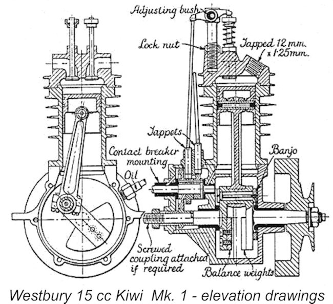
It's useful to compare the Feeney with a similar design from the same period but from a different side of the pond. In 1935, the British magazine “Model Engineer” published E.T. Westbury's 15 cc "Kiwi" overhead-valve four-stroke design, which was intended primarily for model hydroplane use. Superficially, the designs are similar, with a vertically split crankcase, two compression rings and vertical overhead poppet valves. Both utilize a "full" single throw crankshaft, although the Kiwi utilizes straight-cut gears to drive the cam shaft, which is necessarily oriented fore-aft. However, Westbury's design is more sophisticated in the lubrication and carburation departments, reflecting his greater experience. It was a surprisingly perky performer, being capable of reaching 40 MPH in a tethered hydroplane! The Westbury-designed "Apex Minor" of a year or so later used spiral-cut gears, but did not feature the full crank. Westbury's late-1940’s "Channel Island Special" 10 cc overhead-valve design also used spiral gear-driven cams and was manufactured commercially from 1949 through the early 1950's, making it a near-contemporary of the still-born Leja (see below) and showing that the overwhelming impact of the glow-plug on the US model engine market was not felt immediately outside of the USA. The Return of Leja
The Leja was a truly beautiful design owing little to the pre-WW2 Feeney - it was clean, streamlined and functional. The 16.3 cc engine featured straight-cut gears to drive the camshaft. It was also provided with a needle valve for fuel metering - a lesson had seemingly been learned! Finally, it featured beam mounting, completely resolving the mounting issues presented by the original Feeney design. It would be 30 years before any four-strokes of comparable elegance began to emerge from Japanese makers. Intended to sell at $35.00 on the 1948 market, the Leja was another design that was unfortunately run over by the glow-plug revolution initiated by Ray Arden in late 1947. Despite having expended $60,000 in development, dies and tooling, Leja and Hoffman abandoned the project after a small handful of these engines had been manufactured. No other information has been found about Hoffman, although it is apparent that his association with Leja must extend back to at least the late 1930's, since it is his name that appears as the author of the referenced "Air Trails" article that introduced the Feeney prototype. He may have been either an employee or an associate in Leja’s machine shop business. If any reader knows more about Hoffman, please get in touch! Latter-day Feeneys
Ron Chernich's close examination of the drawings revealed the addition of a small bushing to the front crankcase half, and an option to fit a thin-wall cast-iron cylinder liner. The drawings also call out the piston as cast-iron - it's possible that the contemporary reference to steel being used in the original may be in error, as may the cited lack of a shaft bushing. A sampling of the raw castings supplied in the kit appears in the accompanying photograph. I have no knowledge regarding how many of these kits were sold or how many engines were completed from them. At Ron Chernich’s original time of writing in 2003, Art's Feeney casting sets were no longer available. At that time, Art was still in the casting business, concentrating on vintage outboard engine parts (another manifestation of collector-mania!). However, he was then considering making another small run of Feeney kits.
The one replication effort which definitely did succeed came from the noted Danish/Swedish replica promoter Arne Hende. In 2001 Arne arranged for the production of a series of 100 superb replicas of the post-WW2 Leja 16.3 cc model, following this up in 2004 with a similar series of outstanding replicas of the Feeney Model C. These are truly lovely engines if you can get your hands on one – I never have! Even so, there’s undoubtedly a better chance of finding one of Arne’s efforts than of tracking down an original. Reading between the lines, it's not impossible that the appearance of the Hende replicas may have been the straw that broke the camel's back as far as the planned Art DeKalb kits were concerned. The combination of quality, authenticity and price offered by Arne was very hard to compete with. Conclusion Contrary to a widespread present-day impression, four-stroke model engines go way back to the very earliest years of power modelling in the first decade of the 20th Century. Indeed, the earliest successful model engines were four-strokes, many of which were individually constructed by talented model engineers. It was only after WW1 that the two-stroke engine began its move into a position of predominance in power aeromodelling. In some fields of modelling activity, most notably tethered hydroplane racing, the four-stroke engine held its own right up to the onset of WW2 and even beyond. A detailed article covering the earliest years of model engine development may be found elsewhere on this website. The commercial appearances of the Hallam, Grayson and Feeney four-stroke models between the two world wars in England and America respectively as well as the 1949 appearance of the Channel Island Special and the 1958 introduction of the Gannet 15 cc unit kept the four-stroke banner flying during a period when the technology was in a state of more or less total eclipse in the aeromodelling world. In doing so, these engines paved the way for the eventual return to prominence of next-generation four-stroke model glow-plug engines from Japan, Britain, Germany and elsewhere. An achievement well worthy of our respect! ________________________ Article © Adrian C. Duncan, Coquitlam, British Columbia, Canada First published November 2026
|
||||
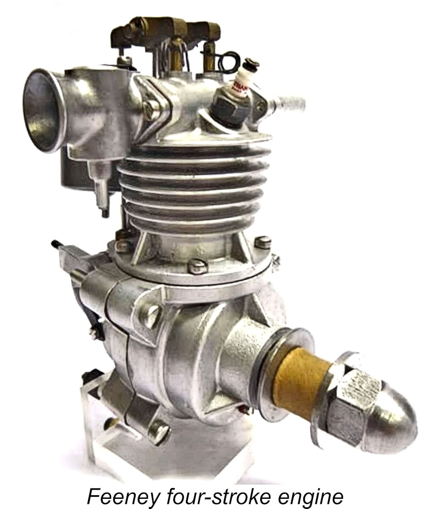
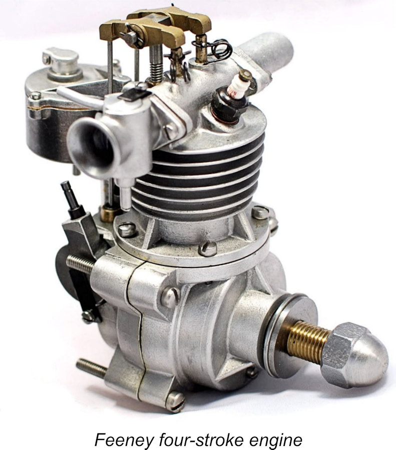
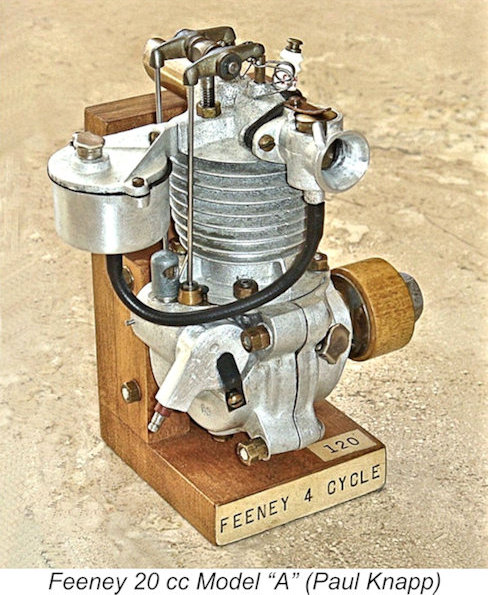 Here we take a look at a rare and highly individualistic American model engine range which made a brief appearance immediately prior to America’s late 1941 entry into WW2 – the Feeney four-stroke models. Although they had been preceded by a number of European designs, these engines were among the first, if not the very first, miniature four-cycle engines intended for use in models to be manufactured commercially and sold in the USA.
 The basic design of the Feeney engines was the brainchild of a Chicago-area resident named Casimir Leja ("Cass" to his friends). Cass was a well-known aeromodeller who had achieved recognition for his accomplishments in rubber-powered events during the 1920's and early 1930's. However, disillusionment with certain contest judging practices which were then prevalent in the Chicago/Cleveland area led to him abandoning aeromodelling in the early 1930’s for involvement with motorcycle racing. It's odd how many model engine enthusiasts were also motorcycle racers - I know at least three other currently-active individuals apart from myself who were involved with both activities.
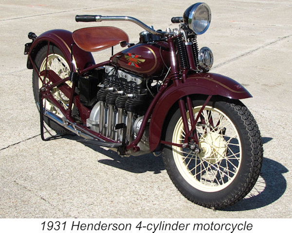
 maintaining the Chicago-built Excelsior and Henderson motorcycles, many of which were still in service despite the fact that their manufacture had ceased in 1931.
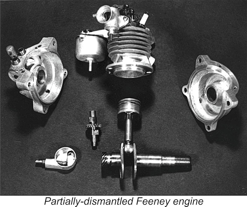 Hopefully the accompanying view of a partially-dismantled example of a Feeney engine will help to clarify many aspects of its construction. The references indicate that all models of the engine utilized identically-formed castings and were built to a common design, only the bore and stroke changing with the displacement. Mechanically, the Feeney was a straightforward four-stroke overhead-valve design, albeit with a few unusual features.
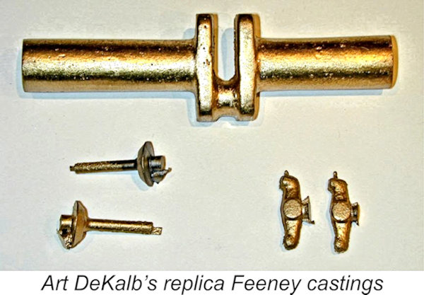 accompanying image shows one of Art DeKalb's replica crankshaft castings along with those for the valves and the rocker arms.
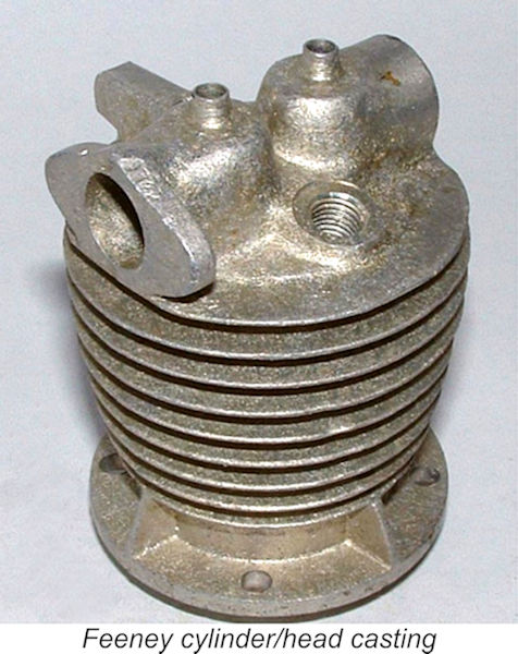 The piston was reportedly made of steel and was fitted with two compression rings, the lower of which doubled as a circlip to retain the fully-floating wrist pin (!!). Note that this would have compromised its sealing potential, since gas would be free to flow around behind it in the wrist pin bosses and re-access the bore below the ring, thus behaving as if the ring wasn’t there – a highly questionable design! The piston ran directly in the aluminium cylinder, generally not a recipe for a long and happy life.
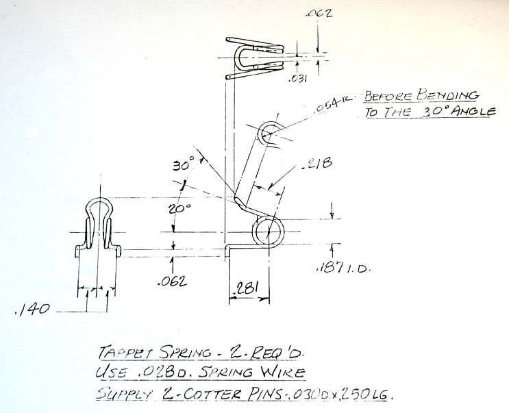 The valves were held closed by rather unusual but artistically attractive hair-pin springs. These were very reminiscent of the springs used in the classic Ducati single-cylinder OHC motorcycles from Italy that I once rode both on the street and on the road racing circuit. Factory instructions recommended a tappet gap of 0.007 in. - rather large by today's standards. Art DeKalb's accompanying drawing shows the specification of these springs very clearly.
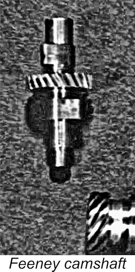 were - guess what? – aluminium-bronze alloy once again. This was achieved by machining appropriately-aligned "D" sections on one stub end-shaft of each cam. The two D sections mated to form a cylindrical shaft over which the cam drive gear could be assembled. Finally, the gear was fixed by soldering the three parts together (in a jig, one hopes). This assembly was inserted into a housing in the rear crankcase half which incorporated one end of the cam shaft journal. The other end of the journal was incorporated into a cover plate that held the cam assembly in place and doubled as the inner half of the timer case.
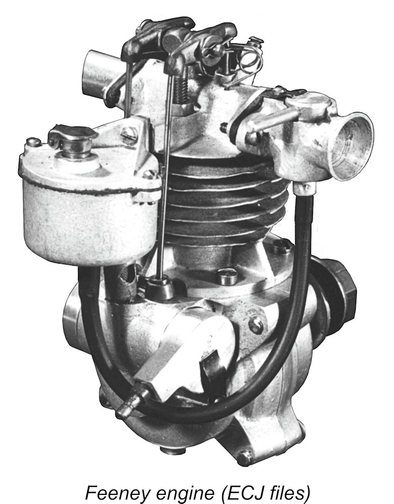 The section of the cam journal that protruded through the cover plate was milled with a flat to actuate the timer points. These were fitted to a carrier that slipped over the cover plate and served as the outer cover of the timer. Friction for setting retention was provided by a "finger" spring (clearly seen in the heading image above) which pressed against the outer face of the timer cover, allowing the point assembly to be rotated for advance/retard. The promotional image seen below at the right shows a different arrangement, so it probably shows a re-touched prototype.
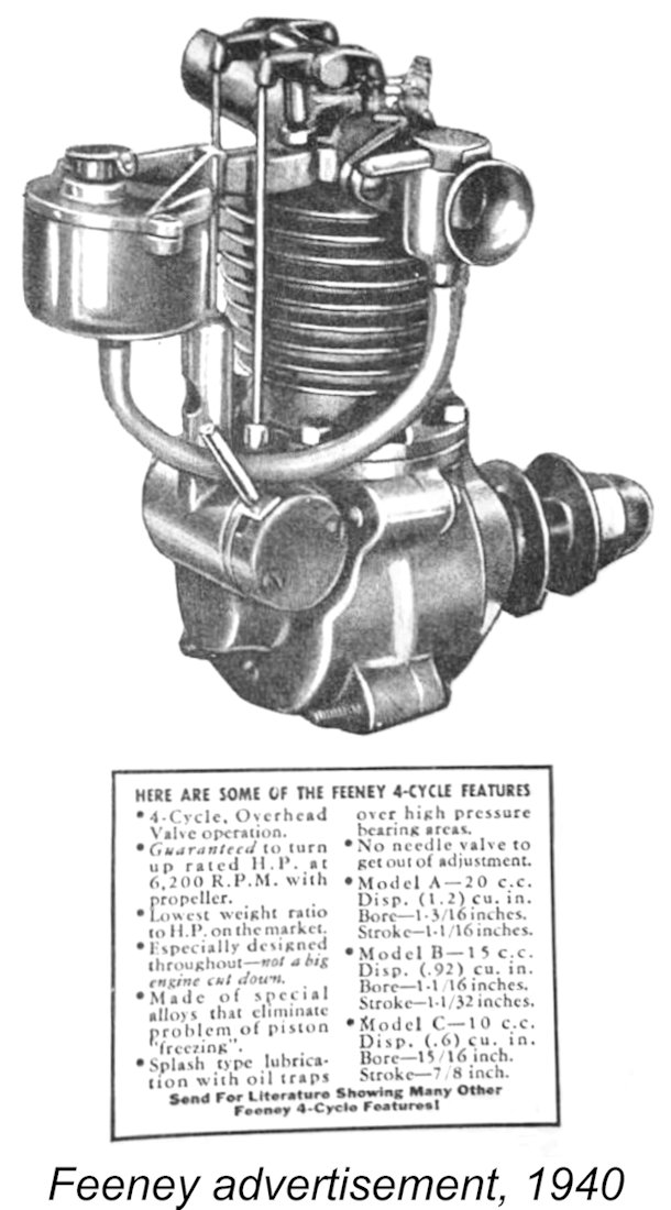 rotated to restrict the airflow. Fuel was admitted by a brass tube jet that protruded into the axis of the barrel within the "slot" - much like the standard drilled barrel of modern R/C carbs. There was no fuel metering. Yup, you heard right! No needle valve, no nothing! The ads even bragged about this feature, as seen in the scan at the right.
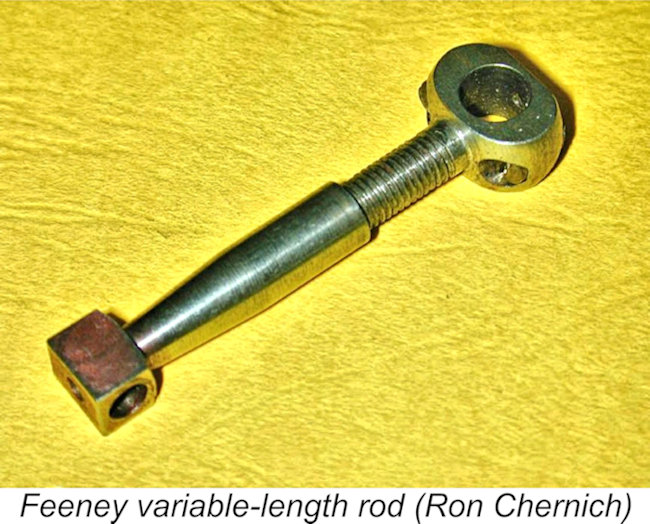 The other (pictured here) was what Ron Chernich was moved to term a brilliant innovation that he was pleased to say never caught on! This was a steel rod which was machined in two halves (plus the end-cap, of course). The portion of the rod column attached to the big end was externally threaded, while the other half of the rod column attached to the small end was internally threaded. The rod was completed by screwing the two halves together, presumably using a very closely-fitted thread to ensure columnar stability.
 suggest that the rod bearings were expected to be more or less self-aligning. This might work in theory, although the arrangement seems to represent quite a lot of trouble to go to in response to a non-problem, given how tolerant sparkies generally are of compression ratio variations. But given the rather rudimentary carburation on the Feeney, maybe the assemblers felt that they needed all the adjustments that they could get!
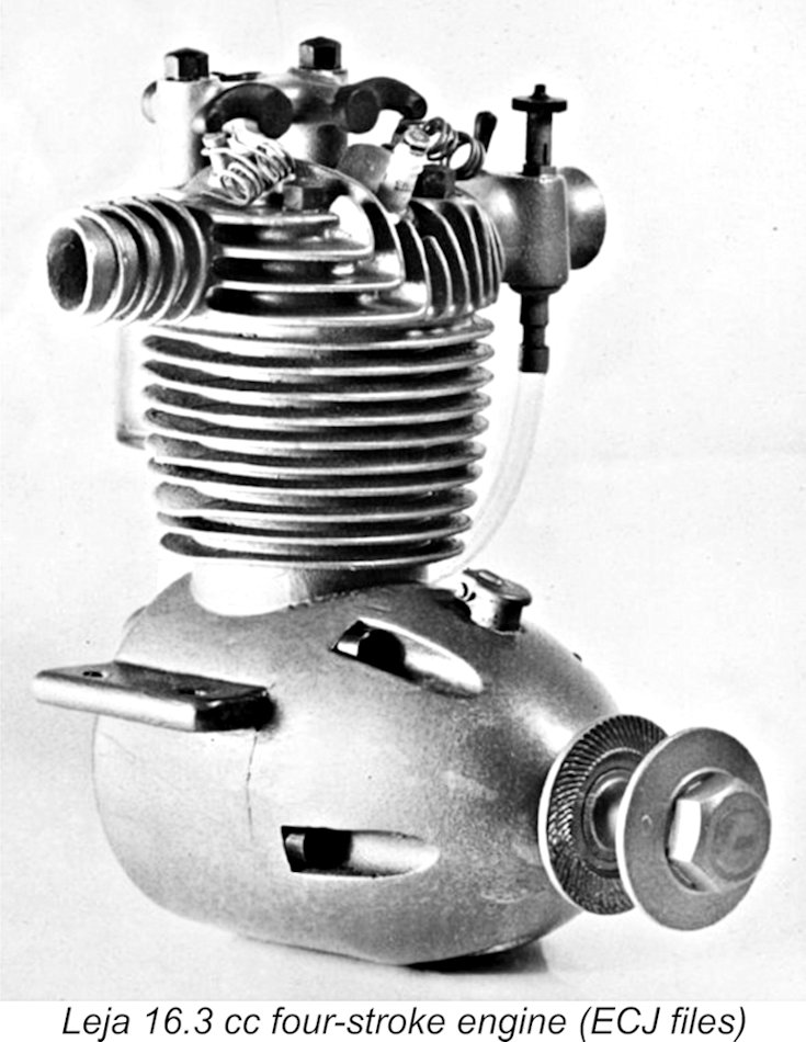 The National Defense build-up for WW2 caused business to boom for many engineering companies, including Casimir Leja's machine shop (remember him?). However, model engine development and manufacture had to cease for the duration as other priorities took centre stage. There's no indication that Jack Feeney re-entered the model engine business after the war, but Cass Leja made a noteworthy attempt to do so, collaborating with R.J. Hoffman in the development of an engine designated as the "Leja Engines 4 Cycle" unit.
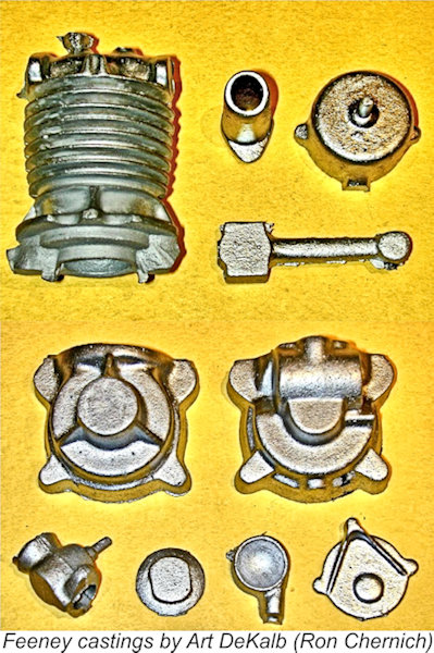 Comparatively modern-day Feeney casting sets were produced in the early 1980's by the Precision Service Company run by Art DeKalb. Art's casting sets reproduced the cast aluminium-bronze crankshaft, the conrod, valves and rockers, the intricately cored aluminium cylinder, and other aluminum parts. The kits were quite complete and included a full set of machine screws plus the necessary spiral-cut gears that were generally beyond the capabilities of even well-equipped home workshops. Like Art's other kits, the Feeney included professionally-drafted full size drawings (running to 45 sheets) detailing all components, including tolerances as appropriate.
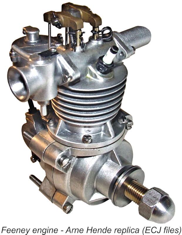 The cruncher was the pair of spiral-cut cam drive gears. These were not your standard Boston Gear catalogue item, hence having to be specially made. To get the price of their manufacture for inclusion with the kits down to an acceptable figure, Art needed to take actual hard cash deposits for eight to ten kits before committing capital to the venture. Art hoped to produce the 10 cc and 15 cc versions which would sell for US$200, plus shipping and handling. But that was back in 2003 - I have no knowledge regarding the fate of this venture. If any reader knows more, let’s hear from you!
| |