Beyond the Box – the RCV Four-Stroke Engines
 As regular readers of this website will know, I invariably focus my writing efforts on subjects that engage my personal interest in one way or another - I do this for fun! In general, I tend to focus on engines from the classic and pre-classic eras which encompass the remarkably long and surprisingly rich history of model engine development leading up to the post-classic Schnuerle-porting era which began during the early to mid-1970’s. From that point onwards, model engine design increasingly devolved into a formulaic state, with engines from different commercial makers exhibiting fewer and fewer technical differences. There was far more technical variety and hence interest in the earlier engines which held sway during the period leading up to my own long-ago embarkation into the world of power aeromodelling.
However, once in a while a latter-day model engine designer managed to find a way to step well outside the box to produce something really original from a technical standpoint. I’ve always been attracted to engines which display some really novel design feature(s), regardless of age. The RCV engines which are the subject of this article constitute just such a case.
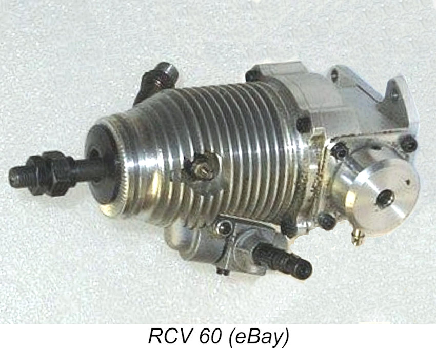 These highly unusual engines were manufactured by a company calling itself RCV Engines Ltd. of Wimborne, Dorset, England. Production commenced in 1997 with the appearance of the 10 cc RCV 60 unit. Additional models were introduced periodically down to 2005, with manufacturing continuing until 2013. At that point, the RCV company branched out into making larger engines for motorcycles, power tools and UAV’s, divesting themselves of their model engine range in the process. This was likely due to the rapidly-shrinking market for I/C model powerplants in the face of the soul-less and totally uninspiring electric take-over which has emasculated power aeromodelling in my personal view.
The manufacturing rights to certain RCV models were taken up by Alan Greenfield of Weston UK, who made some very effective improvements to the designs and continued to offer them in their “Westonized” form. The engines offered by Alan were actually manufactured to his specifications in Shenzhen, China by the Sanye Precision Machinery 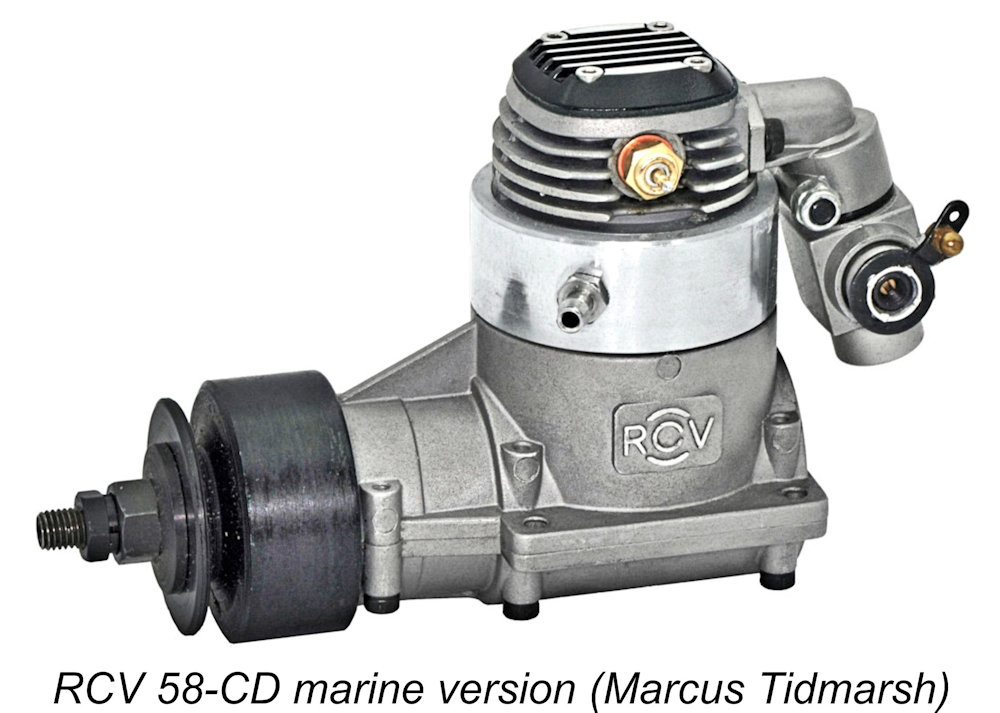 company, who also manufactured such brands as ASP, Magnum, SC, AP, Evolution, GMS, Super Tigre and Kyosho, among others. Most of the Chinese-made RCV engines were air-cooled, but a small number of marine versions were sold by Weston.
The RCV engines still appeared as a generic entry on Weston’s website as of 2026, but an email inquiry revealed that they are no longer available in reality. The Sanye Precision Machinery company ended model engine production in 2019 as the world market for glow-plug engines collapsed, and June Greenfield told me that after doing so they failed to return the molds to Weston. So that was that! A few spare parts and some helpful advice remain available from Weston, but that’s all.
The RCV engines were all four-stroke glow-plug units. “So what?” you might be thinking – “Four-stroke glow-plug engines were two-a-penny in the late 1990’s and they all followed a well-established design formula!” 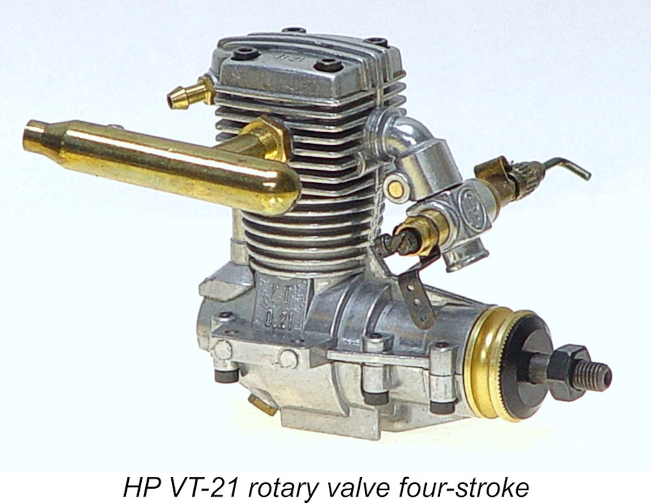 True enough, but these engines were very different! Imagine if you will the challenge facing the designer in coming up with a four-stroke engine that incorporates only one more moving part than a comparable two-stroke unit! This was the challenge facing RCV designer Keith Lawes, and he rose splendidly to the occasion!
Keith began with the idea of eliminating the poppet valves used in conventional four-strokes, along with the associated camshaft, cam followers, pushrods, valve springs, spring keepers, valve seats, rockers and rocker bearings. He wasn’t the first four-stroke model engine designer to look at the use of a rotary valve to control the induction and exhaust cycles - HP, Condor and Webra had all previously marketed four-stroke model engines having rotary valves incorporated into their cylinder heads.
The HP units had 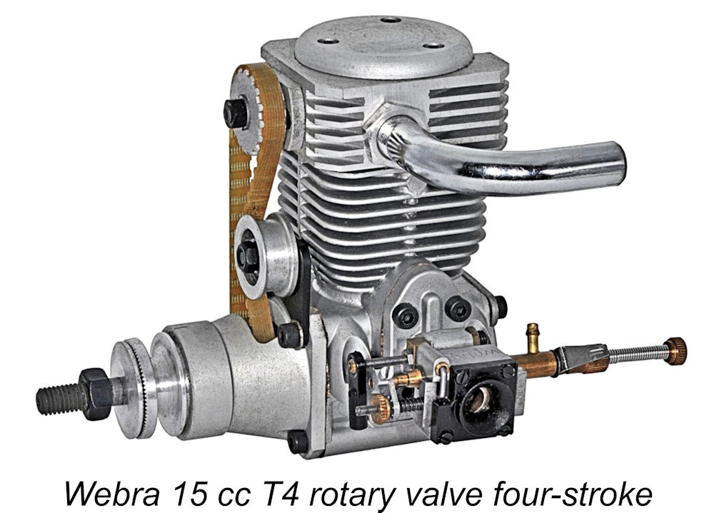 vertically-oriented spur gear-driven rotary valves which were driven by a vertical shaft geared to the crankshaft. The Condor designs from Dennis Allen used horizontal longitudinally-aligned belt-driven valve shafts, while the Webra T4 offerings used vertical rotary valves driven by bevel gears which were themselves belt-driven from the crankshaft, along with a very ingenious crankcase "supercharging" system.
One great advantage of the rotary valve principle applied to a four-stroke engine is that it completely overcomes the RPM restriction imposed by conventional valve gear in order to avoid valve/piston crown contact and valve tangling (two valves making contact with each other) as a result of valve train inertia. With a rotary valve arrangement, there are no mechanical limitations to the engine’s operating speed. Another advantage is the elimination of the need to manufacture up to 20 or more individual components which together make up a conventional poppet valve train. This offers the prospect of manufacturing cost benefits. Finally, there are no valve clearances to adjust.
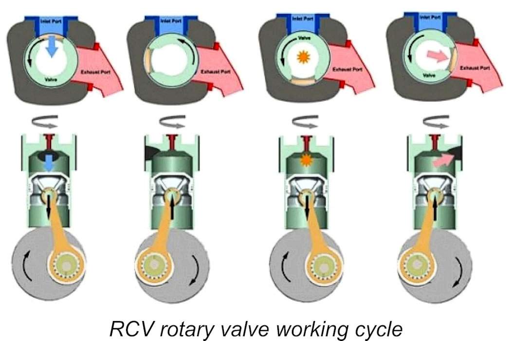 The earlier efforts of HP, Condor and Webra to harness this technology had been very impressive, but Keith wondered if the concept could be taken even further. His great eureka moment came with the insight that if the valve in the head had to rotate, what was preventing the whole cylinder liner from rotating as well? After all, the piston already moved longitudinally inside the bore - why shouldn't it do so helically?
If this could be made to work, cylinder liner and valve could be merged into a single component. Moreover, the rotating cylinder liner could double as the valve-actuating component by being driven by gearing at its base directly from the crankshaft. Thus was born Keith’s highly innovative RCV (Rotating Cylinder Valve) four-stroke concept.
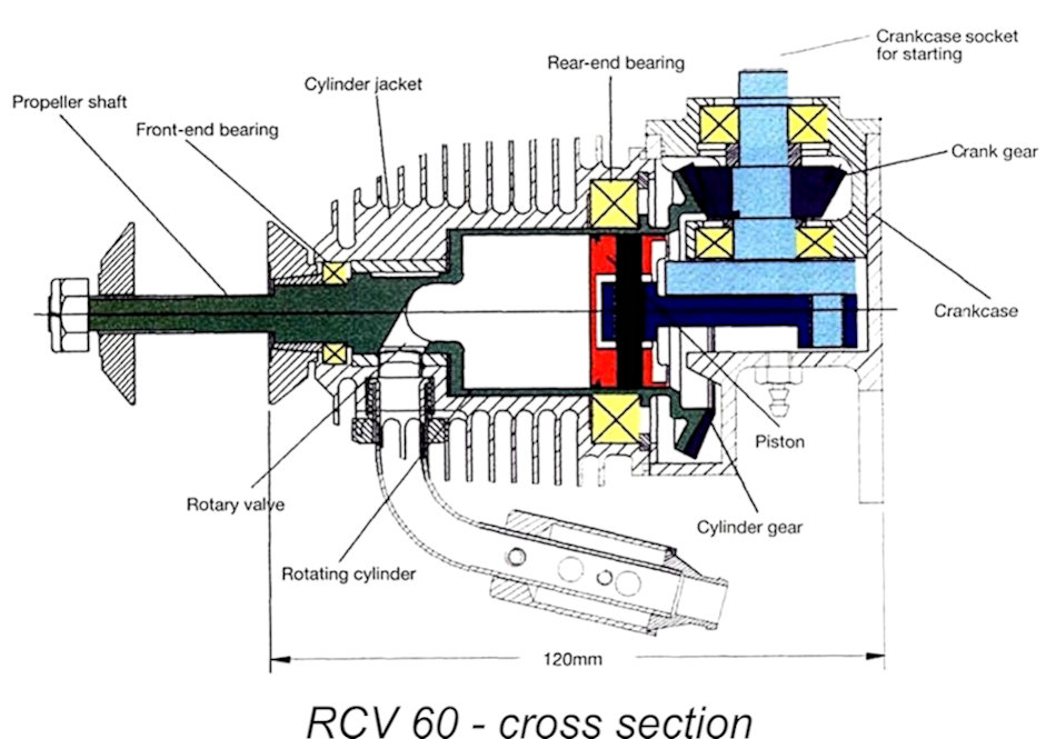 In itself, this alone was an impressive example of thinking well outside the box. However, it didn’t stop there! Keith reasoned further that if the cylinder liner was going to rotate in order to drive the rotary valve, what was to prevent it from driving the prop as well?!? Since the valve-cylinder combination would have to rotate at half crankshaft speed in order to make the four-stroke cycle work, the prop too would have to rotate at half crankshaft speed. This held out the prospect of an engine developing massive levels of torque at relatively low operating speeds, allowing the use of very large high-pitch airscrews.
In effect, this would be a four-stroke engine driving the airscrew through a 2:1 reduction gear set. Perfect for large scale models which could provide the necessary ground clearance for the very large-diameter airscrew or could legitimately feature three or four-bladed props of smaller diameter! Of course, the option remained open to have the prop driven directly by the crankshaft in the usual way, with the rotating cylinder’s role being confined to driving the rotary valve.
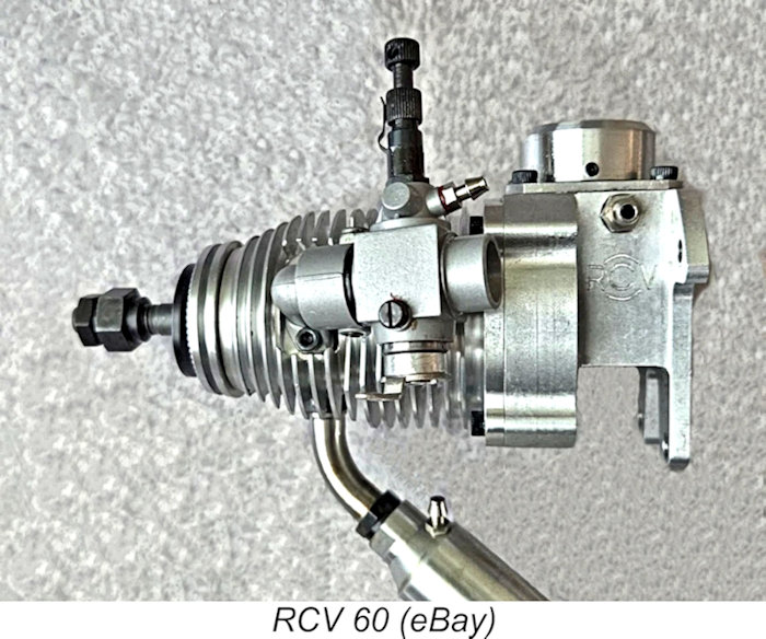 The first commercial manifestation of this design concept came in the form of the 1997 release of the initial version of the 10 cc RCV 60 model. This unit utilized the concept of having the rotating cylinder drive the prop as well as the valve, giving it a unique “horizontal beehive” appearance. It was of course very amenable to cowling, but did require a larger-than-normal ground clearance in view of the abnormally large prop required. Reviewer Steve Dorling commented that he found a 16x12 airscrew to suit the engine very well.
Modeller reaction to the appearance of this engine was somewhat mixed. Steve Dorling recalled one of his modelling friends commenting that the engine looked to him like “a solution looking for a problem to solve!” This individual was understandably fascinated with the ingenuity of the engine’s design but found the results achieved to be “unimpressive”. Other comments recorded by Steve included the engine being characterized as “a cement mixer of an engine” as well as being “noisy”, “rough” and “gutless”.
These comments naturally found their way back to the manufacturer, who instituted a series of improvements resulting in a steady enhancement of the engines’ performance and reliability. The RCV engines ended up earning a solid reputation as dependable and long-lasting model powerplants which performed more than adequately for the majority of uses to which they were put, also achieving better-than-average fuel economy. Their ease of cowling made them particularly attractive for use in scale and semi-scale models. They were supplied in attractive multi-colored boxes along with the appropriate Allen wrenches and a very comprehensive instruction manual.
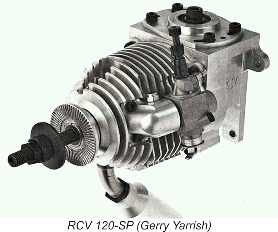 The RCV 60 was followed in 1999 by the similarly-configured 20 cc RCV 120 (which appeared in 2001 in an improved Mk. II version) and the 2002 15 cc RCV 90. The improved versions of these engines were smooth and relatively quiet runners having more than adequate power for non-contest use, but they suffered from a tendency to overheat, probably due in significant part to the orientation of the cooling fins at 90º to the airflow - some creative ducting of the cooling airflow in the model was called for. It was doubtless for this reason that the manufacturers recommended that these engines be operated a little on the rich side. Sound advice ……….
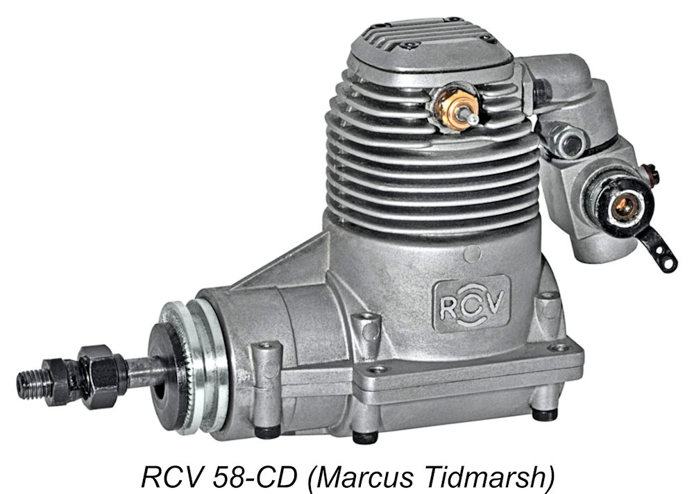
In late 2002 the manufacturers released the first of their more conventionally-styled crankshaft prop-drive units, the 9.49 cc (0.579 cuin.) RCV 58-CD (crankshaft drive) model. These CD 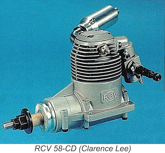 designs were likely motivated by a desire to circumvent the overheating problem which had bedeviled the earlier units. At that point, the cylinder prop-drive models were given the suffix SP (shaft port) in recognition of the fact that the cylinder/valve unit which timed the porting was now part of the propeller shaft. A total of six different models ended up being produced, all of them being constructed using the rotating cylinder principle.
The 2013 takeover by Weston UK involved only the three crankshaft-drive CD models – the three SP designs were abandoned altogether at this point. Over 12,000 engines in total had reportedly been produced by RCV Engines Ltd. at the time of the takeover. A considerable proportion of these were sold in the USA.
A surprising number of the RCV engines became the subjects of published tests in the modelling media. If anyone requires more information than is presented here, these reports are well worth perusing. Those of which I’m aware are as follows:
- RCV 120 --------- Test by Clarence Lee – “Radio Control Modeller”, November 1999
- RCV 120 Mk. II – Test by Clarence Lee – “Radio Control Modeller”, September 2001
- RCV 120-SP ----– Test by Gerry Yarish – “Model Airplane News”, September 2001
- RCV 90 ---------- Test by Clarence Lee – “Radio Control Modeller”, September 2002
- RCV 90-SP ------ Test by Bill Jensen – “Model Airplane News”, November 2002
- RCV 58-CD ------ Test by Clarence Lee – “Radio Control Modeller”, April 2003
- RCV 58-CD ------ Review by Bill Jensen – “Model Airplane News”, date unconfirmed.
- RCV 58-CD ------ Review by unconfirmed writer – “Fly RC Magazine”, February 2004
- RCV 91-CD ------ Review by Andrew Coholic – “Fly RC Magazine”, January 2005
- RCV 130-CD ----- Test by Steve Dorling – “Aviation Modeller International”, January 2011
I’m not an R/C guy, but I do have a used and somewhat abused example of the RCV 58-CD unit on hand for testing – engine number 2297. I purchased this engine from an estate sale purely out of curiosity to experience the operation of such an unusual model I/C engine for myself. But before I get to that, a description of this refreshingly “different” engine is in order.
The RCV 58-CD Described
 When you first clap eyes on it, the RCV 58-CD just plain “looks different” and a bit puzzling! At a passing glance it might be taken for a conventional two-stroke engine. A closer look confirms that it must be a four-stroke engine given the locations of the intake and exhaust up in the head. However, where’s the valve gear - is it a side valve unit like the VEGA models? The absence of the familiar OHV valve gear cluster on top of the head gives the engine an unusually squat appearance – it’s actually little if at all larger than a conventional two-stroke unit of similar displacement, although it is somewhat heavier.
 Beginning as usual with the tale of the tape, the RCV 58-CD features bore and stroke dimensions of 24 mm (0.945 in.) and 21 mm (0.827 in.) for a calculated displacement of 9.50 cc (0.580 cuin.) exactly. One wonders why they didn’t go all the way to 10 cc (0.61 cuin.) – that would only have required the bore to be increased by 0.5 mm or the stroke increased by 1 mm. Regardless, the engine weighs in at a checked 517 gm (18.24 oz.) without the muffler and 562 gm (20.60 oz.) with the muffler in place.
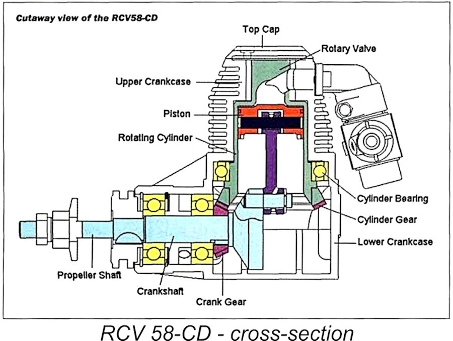
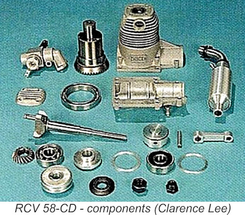
Hopefully the accompanying cross-section drawing and component view will help to clarify exactly what's going on inside this engine. The RCV 58-CD is built up around a complex two-piece main casting which is longitudinally split horizontally along the crankshaft centre 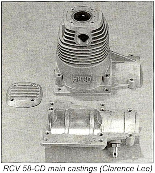 line and held together by six socket-head machine screws. The two ball-races which support the shaft are clamped in place when the two crankcase halves are tightened together around them, although Loctite is also used in the factory assembly. Due to the extreme dimensional precision required in the assembly of the crankcase halves, some form of sealer is used at the interface in lieu of a compressible gasket. Dismantling of this assembly cannot be recommended unless one is forced to it!
The crankcase breather is located on the lower right-hand side of the main bearing housing. This location forces the case to breathe through the rear ball race, ensuring adequate lubrication for the main bearings. 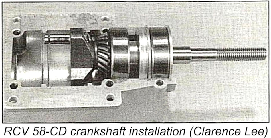 It also serves as a convenient attachment point to facilitate the drawing of after-run oil into the crankcase - always a good thing to do before storing a four-stroke engine for any length of time.
The heavily counterbalanced crankshaft features a pressed-in crankpin which has a groove formed at its outer end. The groove accommodates an E-clip which together with a washer restrains the rod big end from wandering off the crankpin. The rod itself is machined from bar stock and is equipped with bronze bushings at both ends.
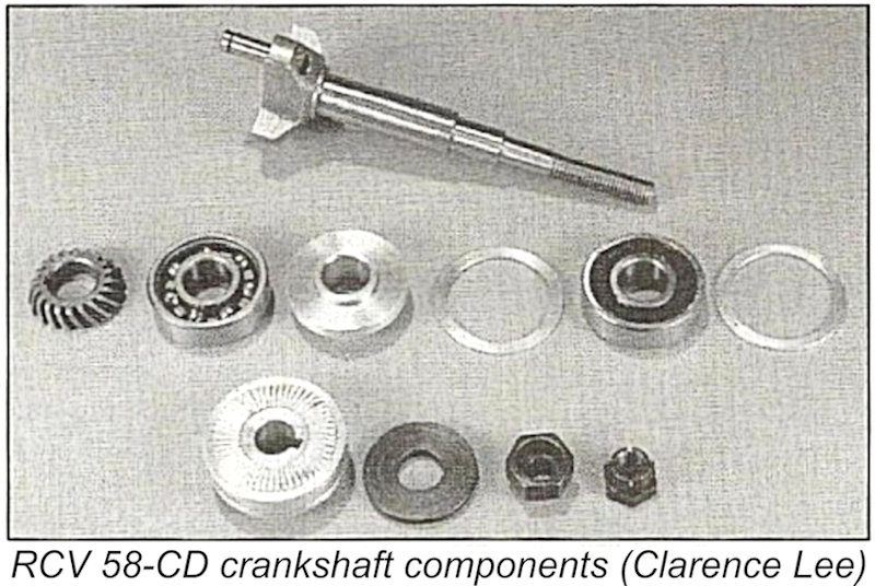 A spiral-cut bevel gear is keyed to the crankshaft with a Woodruff key. This gear drives the rotating cylinder liner at half crankshaft speed. The cylinder liner is made of hardened steel, with its bevel drive gear at its base being pressed or shrunk in place. It is supported at its lower end by a large-diameter ball bearing and at its upper end by the very close fit of the integrally-formed reduced-diameter rotary valve spigot in a pressed-in sintered or cast iron sleeve bearing with ports cut at the appropriate locations. This bearing is further secured with Loctite. Once again, do not disturb!
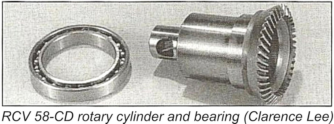 The blind-bored rotary valve spigot is equipped with a suitably-located aperture that exposes the exhaust, intake and ignition conduits in turn as the cylinder liner and valve spigot rotate together. This aperture is clearly visible in the photograph at the right. The valve spigot's interior serves in effect as the engine’s combustion chamber. This will obviously cause the valve bearing to operate at a very high temperature, probably explaining the manufacturer's advice that 6% of the fuel be castor oil, which remains the best high-temperature lubricant of them all. The assembly is sealed at the top with a cover plate which is secured using four socket-head machine screws. Note that this is not a cylinder head – its function is to prevent oil seepage at this location.
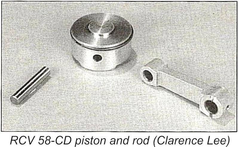 The piston which operates inside the rotating cylinder liner is machined from an aluminium alloy casting. It is unusually short, being only half the height of its diameter. It is fitted with a single unpinned piston ring. The fact that this ring is unpinned seems a little surprising - it is bound to rotate in its groove, with a high potential for wear of the ring's vertical thickness. On my example, the seal provided by this ring remains satisfactory despite the previous use and abuse to which the engine has been subjected.
An unusual feature is the presence of a low spigot on the piston crown which protrudes into the combustion chamber at top dead centre. Presumably this represented an adjustment of the compression ratio, which works out at around 9.6 to 1 as supplied.
 If you’ve been keeping track of the above description, it should have become apparent at this point that the RCV 58-CD incorporates only one additional moving part by comparison with a two-stroke equivalent. This is the rotating cylinder and valve. From two-stroke to four-stroke with one extra working component – a truly remarkable engineering accomplishment!
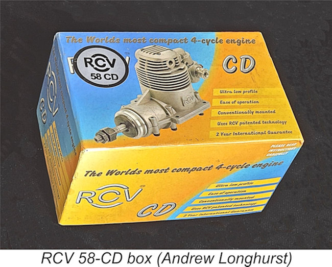
The RCV 58-CD was supplied in an attractively-decorated box complete with both a curved screw-in exhaust pipe having a neat dual-chamber muffler and with an R/C throttle apparently outsourced from an Asian origin - probably from Sanye. The throttle could be positioned with the needle on either side, while the exhaust pipe was held in the desired orientation through the use of a lock-nut. The engine was supplied with an O.S. “F” (four-stroke) glow-plug, which was the manufacturers’ recommended fitting. An APC 11x6 was the recommended airscrew, along with 15% nitro fuel having a synthetic/castor lubricant base.
So now you know how this very ingenious system works! All models in the RCV range functioned in the same way, the only variable being the point at which power to the prop was taken off. Next question – what are these engines like to run? Let’s have a go at finding out!
The RCV Engines on Test
As summarized above, the RCV 58-CD was featured in three published tests of which I’m aware. In the test by Clarence Lee which appeared in the April 2003 issue of “Radio Control Modeller”, peak output was estimated to be of the order of 0.95 BHP @ 12,000 RPM – perhaps a little generous. The manufacturers’ recommended APC 11x6 was spun at 11,200 RPM. Bill Jensen didn’t do quite as well in his review of the engine for “Model Airplane News”, only coaxing the engine up to 10,900 RM on the APC 11x6.
Marcus Tidmarsh’s very interesting “Model Engine World” website summarizes the peak output figures for the various RCV models as follows:
- RCV 60-SP – 0.90 BHP @ 5,800 airscrew RPM
- RCV 90-SP - 1.30 BHP @ 5,800 airscrew RPM
- RCV 120-SP – 1.80 BHP @ 5,800 airscrew RPM
- RCV 58-CD - 0.85 BHP @ 11,000 RPM
- RCV 91-CD - 1.25 BHP @ 11,000 RPM
- RCV 130-CD - 1.50 BHP @ 11,000 RPM
Note that crankshaft RPM for the SP models is double that of the airscrew.
These figures suggest that the RCV engines were solid if unspectacular performers by the standards of their day. Steve Dorling recalled that much of the manufacturers’ early promotional effort centred around their attempts to convince the aeromodelling public that absolute peak horsepower was very much secondary to reliability, fuel economy, longevity and a compact outline that lent itself very readily to enclosure within a scale or semi-scale model’s cowling, along with the ability to swing the larger props (sometimes 3 or 4-bladed) that often complement such models.
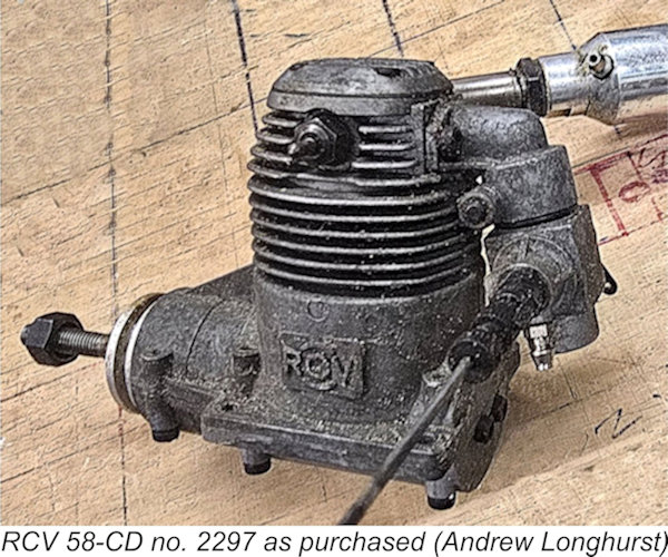 The only example of the RCV range in my possession is the previously-mentioned used example of the RCV 58-CD – engine no. 2297. Accordingly, this would have to suffice as my test subject. At the time when I purchased this engine, I was well aware that it needed a good cleaning, although it reportedly turned over freely with some compression. If anything, it turned out to be even worse than anticipated, clearly having been improperly stored for an extended period of time following extensive use. The attached image gives some idea of its general condition as received. I couldn't completely remove the dark mottled patina resulting from storage under corrosive conditions, but I did what I could. I also managed to get the thottle unstuck after a bit of a struggle.
The engine eventually cleaned up to what I considered to be good average "well-used" operating condition. Worth a try, anyway! The compression turned out to be a little soft, but in 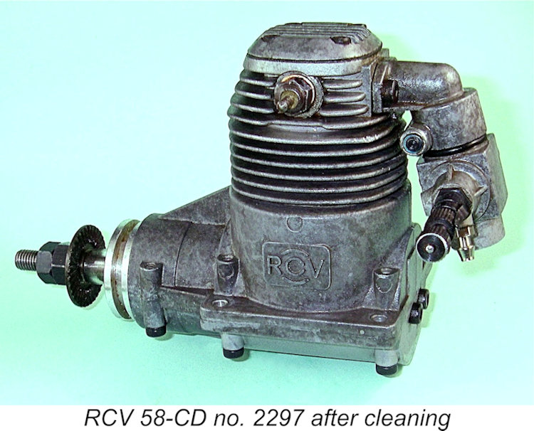 my judgement based on long experience there was enough to run the engine. However, given the fact that the manufacturers recommended the use of an electric starter for this engine, I was expecting a certain amount of difficulty getting it to run because I don‘t own an electric starter and have no wish to break the habit of a lifetime!
My fears proved to be well founded. I could get the engine to pop now and then when flicking the prop over, but I couldn't get a starting burst. My experience matched that of a number of reviewers of the RCV engines, all of whom reported difficulty in hand-starting even a new unit. My example had the additional handicap of the soft compression. However, without exception all of the testers reported instant results using an electric starter. I guess that leaves me out!!
So there we have to leave it. Despite my failure to get my example of the RCV 58-CD to run, I still rate these engines as refreshing and remarkably ingenious departures from the standard design formula for model four-stroke powerplants. I gather that the RCV company has gone on to great success with its development of larger engines using the same technology. I'd say that their success was very well deserved!
__________________________
Article © Adrian C. Duncan, Coquitlam, British Columbia, Canada
First published November 2026