
|
|
The WAF Engines
Before embarking on my self-appointed task, I wish to acknowledge the immense contribution made by my good mate Peter Valicek of the Netherlands. Although produced in some quantity over a period of at least 8 years (and quite possibly more), the WAF 1 is relatively rare outside Europe, and I didn’t have one myself. Without an example of the WAF 1 to examine, photograph and test, I would have been unable to even consider embarking upon this project. Not only did Peter track down an example of the WAF 1 for me, but upon finding that it had a broken crankshaft he then located another “bones” example which supplied a replacement shaft, thus restoring the first example to excellent and completely original condition. He also optimized the piston/cylinder fit. We all need good friends ........and they don't come any better than Peter! A video record of his efforts with this engine may be viewed here. I'd also like to acknowledge the help which I received from another Peter in the person of my German friend Peter Rathke. Peter R. was most helpful in tracking down some basic information about the WAF range. Such assistance from a fellow enthusiast means a great deal to me! Some years ago, the WAF 1 was the subject of a brief descriptive article by my late and greatly missed mate Ron Chernich. Ron’s article may still be accessed on his now frozen but still invaluable “Model Engine News” (MEN) website. Subsequently I personally contributed a similarly brief descriptive article on the very rare WAF 3.5 cc model which evidently never progressed beyond the prototype stage. That article too remains accessible on MEN. However, neither of those articles addressed the issue of dating of the engines, nor did they present any latter-day test results. The present text is intended to remedy both of those deficiencies. I’ll begin by looking at a little background, including the dating question. Background
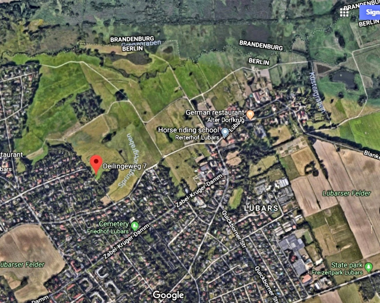
Throughout all the epochal events of the 20th century, the community has somehow managed to maintain its character all along as a quaint, well-preserved historic village or “dorf”, albeit within the borders of Greater Berlin. It still retains a significant number of well-preserved heritage houses and other historic structures, thus presenting a real step back in time to the visitor. It is very popular both with Berlin residents and visitors, being a pastoral little spot that makes an easy day trip for “getting away from the city” without actually doing so! The 39.6 ha recreational park incorporated within the community boundaries is a popular attraction. The accompanying map at the right shows the location of the community in relation to central Berlin.
All of this being the case, it would be interesting to know how a small precision engineering concern became established at this bucolic location. The pastoral character of the village of Lübars strongly implies that the venture was almost certainly based upon a home or “garden shed” workshop operation initiated by a resident of the village.
I’ve been unable to learn anything about the earlier activities or technical education of Walter Frisch. All that is known for sure is that at some point in the early 1950’s he commenced production of a 1 cc diesel engine which he designated the WAF 1, the name being obviously based upon his own initials. A few earlier commentators (including my mate Ron) have cited 1951 as the year in which the WAF 1 entered production. However, this is at odds with the evidence of the generally reliable Peter The coverage of Chinn's article was quite broad, including then-current designs from Webra, Metro, Carl Zeiss, Wilo and BWM in addition to such relatively obscure units as the Kombi-Diesel, the Condor-8 glow-plug model, the Ridi-Diesel and the RGU Universa diesel (later to evolve into the Jaguar range). Despite this seemingly comprehensive overlook, the WAF marque was not mentioned. If the WAF 1 had in fact been introduced in 1951, it seems inconceivable that Chinn’s multiple German informants would not have made him aware of it by mid-1952 for inclusion in his December 1952 article. He clearly went to great lengths to make that article as comprehensive as possible. Further confirmation is to be found in Chinn’s test of the WAF 1 which appeared a year later in the December 1953 issue of “Model Aircraft”. Allowing for Editorial lead time, this test was probably completed in around August or September 1953. In his test report (of which more below), the typically well-informed Chinn characterized the WAF 1 as “a recent addition (my emphasis) to the growing list of German made model diesels”. In context with the omission of the WAF engines from Chinn’s December 1952 article, this seems to amount to confirmation of Chinn’s generally well-informed understanding that the WAF 1 actually appeared at some point in late 1952 or perhaps early 1953. The clincher comes from the fact that my friend and colleague Peter Rathke has uncovered some credible independent evidence from German sources to the effect that Frisch made the earliest examples of the WAF 1 in 1952. If so, it appears that those engines were distributed locally with no fanfare, presumably to assess their reception among modellers who had the opportunity to try them in the field. This actually appears to have been Walter Frisch's normal modus operandi, as we shall see later. This low-key initial approach naturally resulted in the wider aeromodelling world, including Peter Chinn's German informants, remaining unaware of the WAF 1's existence at the time. It appears that the broader commercial marketing of the engine did not begin until late 1952 or early 1953. Unless someone can provide authoritative evidence to refute this view, I will continue to cite late 1952 or perhaps early 1953 as the most probable introductory date for the engine, at least in commercial terms. If you think I’m wrong, please share your evidence! Description
The only competing 1 cc model of which I’m aware that possessed similar internal geometry was the Barbini B.38 from Italy which appeared in 1953. That model featured even more exaggeratedly long-stroke bore and stroke measurements of 10.0 mm and 12.7 mm respectively for a calculated displacement of 0.997 cc (0.061 cuin.). Despite its even longer stroke and consequently “tall” appearance, the Barbini was even lighter at 53 gm (1.87 ounces). As my own tests summarized elsewhere have shown, it was an outstanding performer. To offset its seemingly retrograde long-stroke geometry, the WAF’s cylinder porting was quite advanced for a sports diesel of this vintage. The cut-away drawing from the "Model Aircraft" review which is reproduced below shows some details of the cylinder porting arrangement. A quite unusual feature was the radial array of six small square exhaust ports. Spend a moment thinking about the challenge of creating these small square ports so precisely……
The transfer ports are angled at around 35 degrees from the vertical, resulting in what was basically a six-port Oliver-style transfer arrangement. The transfer ports overlap the exhausts to a significant extent. The cylinder liner screws into the top of the gravity die-cast crankcase using an external thread on its installation flange which engages with a female thread in the upper crankcase socket. In all the examples examined so far by Peter Valicek, the lower section of the liner is considerably smaller in outside diameter than the inside diameter of the upper portion of the crankcase, creating an annular space between the inner crankcase wall and the outer cylinder wall which acts as the bypass. The case diameter is relieved at the top for a short distance below the threaded installation socket to create an annular chamber which surrounds This brings up one of the as-yet unconfirmed factors in the WAF story. Peter Chinn's December 1953 description of the engine specifically mentions the presence of six internal channels which were reportedly milled into the inner wall of the upper crankcase to serve as bypass flutes to supply mixture to the annular chamber and thence to the transfer ports. As a general rule, Chinn was meticulously accurate in his descriptions of major design features such as this, making it appear logical to assume that his test example was so equipped. However, these flutes are absent from any of the multiple examples which Peter Valicek has ever seen. In addition, there's no conclusive evidence of their presence in the previously-reproduced cutaway view of the engine from the same test report. Moreover, there really doesn't seem to be enough metal thickness in the castings examined to date to allow for the creation of these milled flutes. Even if there was sufficient thickness, they'd be redundant given the 360 degree annular space between the lower cylinder and the inner wall of the upper crankcase, which constitutes a perfectly adequate bypass. That said, the thought occurs that a greater thickness of metal could have been made available by reducing the bore of the casting below the annular bypass chamber to match the outer diameter of the lower cylinder. This would allow enough metal thickness to permit the creation of the bypass flutes which this arrangement would obviously require. It would also improve the support offered by the crankcase to the lower cylinder. So the possibility certainly exists that Chinn's description of what must have been a very early example may be correct - such a configuration undoubtedly could have been created. If so, the milled bypass flutes were strictly a feature of the very earliest examples and were clearly abandoned at an early date, presumably for cost-cutting reasons. A side benefit would have been a certain increase in the total available bypass area. If anyone has an example which features the six bypass channels, please get in touch, preferably with an image!
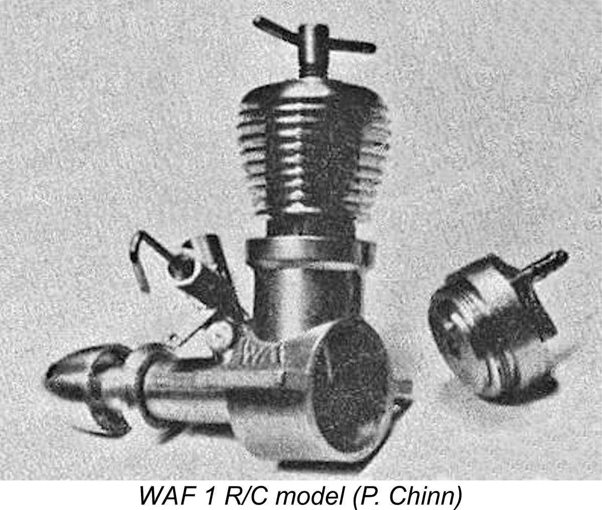
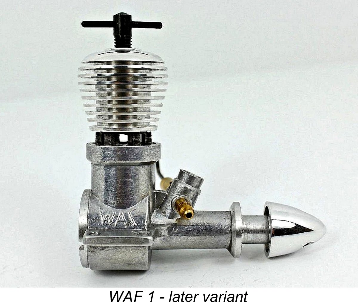
The final noteworthy feature is the comp screw, one arm of which is bent upwards, at least on the earlier examples. If you come into possession of one of these engines, don't be tempted to straighten the apparently bent "tommy-bar" - this is factory standard! The intent was evidently to avoid ambiguity in relation to the position of the compression screw for starting and running. The remainder of the design is quite conventional. The one feature which is perhaps worth noting is the fact that the spraybar is aligned so as to position the needle valve control rearwards and upwards on the left for operator convenience. Very nice for bench testing and sidewinder mounting, but it prevents the assembly being reversed, as might be preferred in certain mounting configurations. This sometimes annoying feature is shared by a number of other ranges, including the Davies-Charlton models. The D-C engines compounded the issue by having their needle valves oriented to the right, making sidewinder mounting highly problematic. The WAF 1 quickly earned a very good reputation among contemporary German modellers, although the numbers in which it was produced by its artisan manufacturer couldn’t match those of competing German firms such as Webra and Taifun. Despite this, it also found its way to other European countries. A Swedish poster on a well-known modelling forum stated that the first model engine he ever saw run (in the mid 1950’s) was a WAF 1. Although he With a reputation like that, it would appear that Walter Frisch was easily able to sell all of his relatively limited output of these engines. As a result, production of the WAF 1 continued for some years. Although best known as an aero engine, the WAF 1 was also offered in a marine version which was equipped with a watercooled head and flywheel. An R/C version of the engine was also developed at some indeterminate point during 1957, although this may never have progressed beyond the experimental prototype stage. Peter Chinn got his hands on an example of this latter variant, which was featured in his “Latest Engine News” column in the April 1958 issue of “Model Aircraft”. Chinn’s description confirmed that this variant featured both a barrel-type throttle on the intake and a vacuum pump-equipped backplate for use with the vacuum-powered control actuators then popular among German R/C fliers. I've always wondered what happened when the engine stopped while the model was still airborne...............
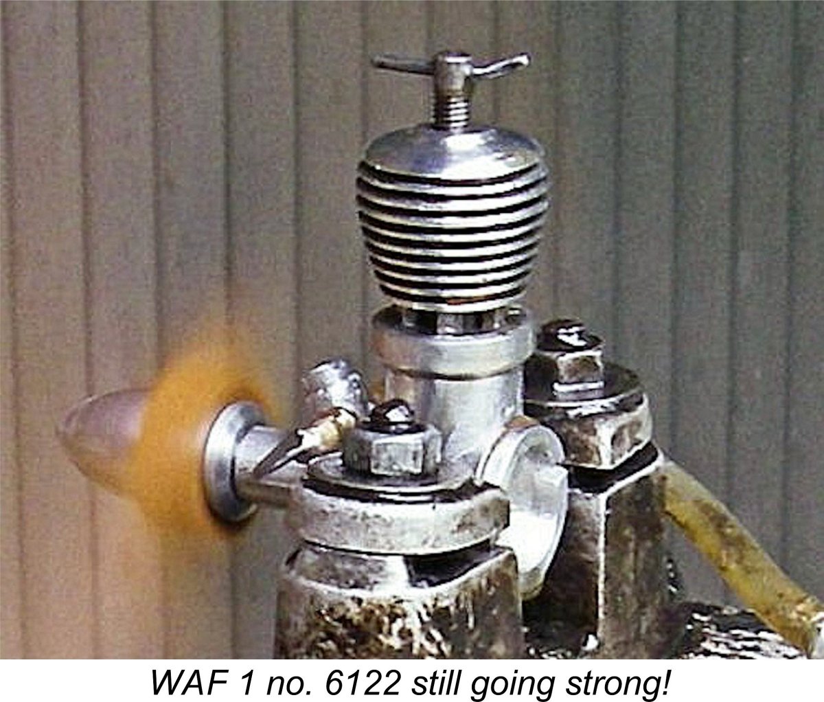
Another change was the inclusion of a "step" in the outer diameter of the induction venturi immediately below its entry point. This may have been a response to difficulties in extracting the castings from the die. In addition, the bend in the arm on one side of the comp screw was evidently omitted at an even later date. There may have been other internal changes as well, but I'm unable to comment on those. In addition to its inclusion in Chinn's April 1958 article, the WAF 1 was featured in a German catalogue dating to late 1957 or early 1958 (based on a dating analysis of the other included models) which is in the possession of Peter Valicek. The only later media references to the WAF 1 that I've been able to find were its inclusions in the diesel tables of both the 1962 and 1964 "Global Engine Review" compliations which were published in the "American Modeller Annual" for 1963 and 1965 respectively. Although unattributed, these tables and accompanying text were almost certainly compiled by Peter Chinn. The WAF engines are conspicuous by their complete absence from the text of either edition of the review, leaving one to wonder if their inclusion in the tables may actually be taken as evidence of continued production or should rather be seen as either an editorial oversight or an indication of continuing availablility as New Old Stock. One straw in the wind is the instruction sheet with my own boxed example which was so capably restored by my good friend Peter Valicek. That sheet is hand-dated 9.8.60 along with an owner's stamp (another Adrian, this time from Munich!), seemingly implying that it was acquired in 1960. This example bears the highest serial number yet reported (6122), which is consistent with the notion that it is one of the later engines and that production was evidently still ongoing as of 1960. Of course, it could have been sold in that year as previously-manufactured New Old Stock. At present, there's no independent evidence for production beyond 1960 apart from the entries in Chinn's tables, the significance of which appears questionable. In terms of production figures, we get some help from the fact that the WAF 1 engines all seem to have borne serial numbers stamped into the underside of the right-hand mounting lug. The highest serial number of our present acquaintance is my own previously-mentioned engine number 6122. Peter Valicek owns engine number 4393. The implication is that the numbering system started at engine number 0001 (or perhaps 1000) and that over 5,000 examples were undoubtedy made - possibly more. If any reader is able to extend the range in either direction, I'd love to hear from you!! Numbers below 1000 or higher than 6122 would be of the greatest assistance. The WAF 1 on Test The WAF 1 was the subject of a very favorable review in the December 1953 issue of “Model Aircraft”. Although unattributed, this review was almost certainly written by Peter Chinn. It was in this report that Chinn mentioned the six internal bypass channels discussed earlier. The reviewer had little but praise for the engine in general, characterizing it as “a nicely finished unit, easy to handle and surprisingly powerful”. The report went on to praise the engine’s “easy, prime-less starting, good performance over a useful speed range, smooth working and positive controls and sound construction”. Sounds a lot like a review of a Mills to me!! Could this be the "German Mills"?!? Chinn found a peak output of 0.090 BHP at 12,000 rpm, which he characterized as “just about the best recorded for a 1 cc unit in these tests”. By late 1953 standards it was indeed a very good performance for a 1 cc diesel - Britain certainly had nothing comparable to offer at the time. This kind of output at moderate revs is unmistakably indicative of better-than-average torque development. Maximum measured brake mean effective pressure was of the order of 53 psi at around 9,500 rpm, which is very good for a 1 cc diesel of the early 1950's. The engine's long stroke doubtless contributed to this characteristic.
Having a nice example of the WAF-1 on hand thanks to the previously-noted kindness of my good mate Peter Valicek, I was keen to second-guess Chinn by running my own test. This example had been expertly rebuilt by Peter, including the re-fitting of the piston to restore a somewhat worn compression seal. Accordingly, I elected to give it a short break-in period to allow the re-fitted parts to become re-acquainted. For this purpose, I fitted a BY&O 9x4 wood airscrew, filled the tank with standard nitrated diesel fuel and got stuck in. Actually, it didn't take much sticking!! The first thing about the WAF that really impressed me was its ease of starting. As Peter so aptly put it, "a schoolboy with two left hands and no idea about how a engine Once the engine was running, it proved to be extremely easy to set. Response to both controls was well marked, with no undue sensitivity but a clearly defined "best setting" with some latitude either way. The engine ran extremely smoothly on all props tried. Despite the long stroke, vibration was by no means excessive. I would rate the running qualities of the WAF 1 as exceptionally good. In view of the fact that the engine had just come from Peter Valicek's workbench, I gave it a 30 minute break-in using the 9x4 wood prop. At the end of this it felt absolutely superb - clearly all ready to give its best during the test. The engine's easy starting, fine handling and ultra-smooth running made this test a real pleasure. The following data were recorded:
The 7½x4 WB prop is a cut-down APC 8x4 which I created to fill a gap in my test set of APC airscrews. As can be seen, this example of the WAF 1 developed a higher peak power output than the one tested by Peter Chinn, but did so at substantially lower rpm. It One point that catches the eye is the fact that the peak of the power curve is notably flat. The engine is developing 0.090 BHP or better at all speeds between 7,700 RPM and 12,000 RPM. This would allow considerable latitude in terms of prop selection. An observation that follows from this is the fact that although it's past its peak at 12,000 RPM, my test engine was still actually developing 0.090 BHP at that speed - exactly the peak output that Chinn measured, and at the same speed! All in all, I'd have to colour myself thorougly impressed with the WAF 1 on the basis of this test. The engine's quality, sturdiness, ease of starting and excellent running characteristics would have made it a very useful addition to the holdings of any sport power modeller fortunate enough to acquire an example. It would have had particular value as an ideal beginner's engine. I know that I would have put one to very good use if I'd had one myself back in the day! Other WAF Models
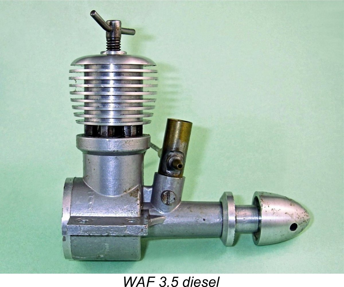
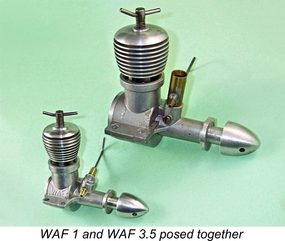
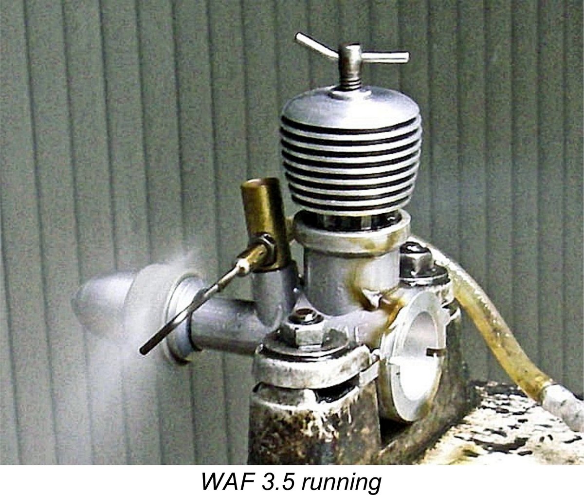
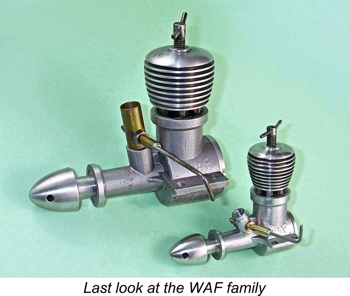
Herr Frisch also experimented with several larger versions of his basic WAF 1 design. Peter Chinn's “International Engine Review” published in the April 1955 issue of “Model Aircraft” includes two distinct WAF models in the table on page 141. The heading photo for the article shows what is clearly a WAF Unfortunately, this engine is not mentioned in the text. However, Chinn is usually reliable, especially when he has sufficient data to quote actual measurements, so I believed that we couild take this as confirmation that at least one 5 cc WAF diesel existed to be measured at some point. My German friend and colleague Peter Rathke confirmed that the existence of this model is an accepted fact among German enthusiasts. He advised that, like its smaller companion, the WAF 5 was a crankshaft front rotary valve unit, designed along the same lines as its smaller relative. However, it is an extremely rare engine today - Peter has never seen one himself. It was probably a short-run experimental model built in very small numbers to test the market. Thanks to the diligence of my previously-mentioned friend Peter Valicek, an actual image of this very rare unit was uncovered some months after the original An engine which does not appear in Chinn’s table is the WAF 3.5 cc model. Nonetheless, there is incontrovertible evidence in the form of an actual example formerly in my possession that Frisch produced a few copies of an experimental 3.5 cc model which was essentially a scaled-up WAF 1. This initiative evidently arose from the strong sales of the WAF 1, which encouraged Frisch in 1954 to consider expanding the range. According to the German seller of this engine (over 40 years ago now!), Frisch made a run of just ten examples of his proposed 3.5 cc model in 1954, both for his own testing and to obtain some practical modellers' impressions. The seller of my example (a German professional airline pilot) stated that he was one of the modellers who was favored by being Visually and structurally, the WAF 3.5 is pretty much exactly like a scaled-up WAF 1, the photographic giveaways being the extended brass venturi intake and the "3.5" embossing on the left side of the gravity die-cast crankcase. The brass venturi insert is a separate component which is secured by a set screw, meaning that it can be positioned to align the needle in any desired orientation. The larger model retains the characteristic "asymmetric bend" comp screw of the WAF-1, the bend at one end presumably being intended to eliminate ambiguity regarding the compression setting. Internally, the porting arrangements are identical to those described above for the WAF 1. The six Bore and stroke of this motor are 15.6 mm x 18.0 mm, retaining the "standard" WAF long-stroke configuration and yielding a displacement of 3.44 cc. At 213 gm (about 7.25 ounces), the WAF 3.5 is undeniably a bit porky in terms of weight, much of which is in the very heavy cylinder. The quality of the engine's construction is every bit as good as that of its smaller WAF 1 companion. As we might expect with a prototype, there is no serial number. For purposes of comparison, the accompanying photo shows the WAF 1 and WAF 3.5 models posed side by side. This image provides a good indication of the WAF 3.5's impressive size. The long stroke of the WAF 3.5 results in the engine being unusually tall for its displacement, just like the WAF 1. This factor gives it a rather "old-fashioned" appearance which may have told against it in potential sales terms. The WAF 3.5 on Test As received, my illustrated example of the WAF 3.5 had clearly been mounted and used, as we would expect with a prototype unit provided to the original owner for field testing. I had run the engine myself many years ago immediately after acquiring it in 1980. Although I didn’t take any prop/rpm figures at the time, my notes from that test record that the engine started easily and ran very strongly, just as reported earlier for the 1 cc model. It was certainly time to re-assess this impression by conducting a present-day test.
Once set up in the test stand with the APC 10½x6 prop fitted, the engine took a little while to awaken from its decades-long slumber. However, using the same nitrated diesel fuel which had been employed during the WAF 1 test, I soon had it going regardless. Subsequent starts were very easy indeed - rather like the WAF 1, in fact. Priming was generally unnecessary, although the engine didn't like getting too much fuel in the crankcase. Just enough and no more was the order of the day. Once running, the engine handled pretty much like its smaller relative - excellent response to both controls, with well-defined optimum settings. Running too was completely smooth and mis-free. The one thing that I did notice initially was a certain tendency to sag a little as things heated up. It transpired that the engine was still pretty tight, evidently having seen insufficient running in the past to free up completely. I therefore gave it a further 20 minute break-in session just to be on the safe side. This did result in a slight but noticeable improvement. Although I had provided myself with only four props which would fit on the engine's monumental 11 mm diameter prop mounting hub, it turned out that these nicely bracketed the engine's peak, thus relieving me of the need to over-bore any more props. The following data were recorded during this test:
Indications are that the engine peaks at around 0.301 BHP @ 10,400 RPM. In other words, like its smaller companion it's all about torque at moderate speeds rather than all-out horsepower. It also has a very comparable specific output (BHP/cc). It's also interesting to note that the 3.5 appears to peak at more or less the same speed as its smaller relative - presumably a reflection of the two models' basically identical design. The implied peak output would have been considered quite respectable for a plain bearing 3.5 cc diesel in 1954. It certainly beat the 0.285 BHP @ 11,900 RPM reported by Peter Chinn in his November 1952 "Model Aircraft" test of the highly-regarded short-stroke AMCO 3.5 PB from England. Moreover, the long-stroke WAF delivered its superior power at significantly lower revs, implying exceptional torque development and a consequent ability to turn a large and hence efficient airscrew which would move plenty of air. My overall impression of the WAF 3.5 was very favourable - it's a very well-made and sturdy unit which starts easily, handles well and runs very smoothly. It also swings a prop of very meaningful size with considerable authority. It would have been a very useable engine in its day, forcing one to wonder why it never saw series production. Conclusion
It appears certain that the WAF 1 was still in production at some level as of early 1958. There's also the evidence of that dated WAF 1 instruction sheet from 1960, although that could represent a unit sold as New Old Stock. However, the complete absence of post-1958 references in any media text that I can find (apart from those "American Modeller Annual" table entries) makes it appear more likely than not that production ceased no later than 1960, and possibly earlier. Still, I could be wrong! Even if I'm right, a potential 8-year production life for an artisan-built design dating back to 1952 is surely indicative of the underlying quality of the engine. Although it was nothing more than a simple sports diesel, the WAF 1 was a very well-made unit having a number of quite individualistic design features along with a more than acceptable sports performance. As such, it doubtless served its owners well. The WAF 3.5 was an equally well-made unit which appeared on test be be an equally useful engine to its smaller relative. However, it was saddled with a somewhat "retrograde" appearance along with higher-than-average weight. Presumably these factors explain why it never saw series production. Realistically speaking, your chances of finding an example of the WAF 3.5 (or its even more elusive WAF 5 relative) appear to be slim to nil. I just got really lucky all those years ago - indeed, I didn't realize just how lucky at the time! However, examples of the WAF 1 do show up from time to time, mostly in Germany. I’d certainly recommend the WAF 1 as a very worthy acquisition for anyone who appreciates well-made model diesels having a character of their own. If you ever get the opportunity, don’t hesitate!! _________________________ Article © Adrian C. Duncan, Coquitlam, British Columbia, Canada First published June 2019 |
||
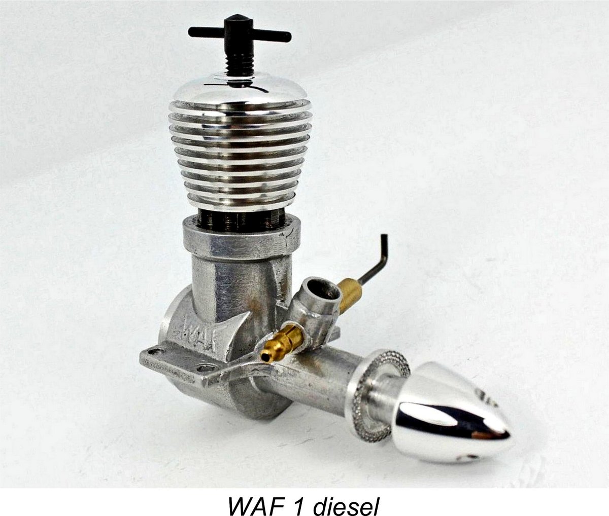 In this article I’ll be reviewing a quality German model engine marque to which relatively little attention has been paid in the English language over the years. This is the WAF series which was the creation of Walter A. Frisch of Berlin-Lübars. By far the most common bearer of the WAF name is the WAF 1 diesel of nominally 1 cc displacement.
  Walter Frisch’s location in Berlin-Lübars is one of the more tantalizing background facets of the WAF story. Berlin is a city which is ever-full of surprises, and the village of Lübars is certainly one of them! Founded in around 1220 as an autonomous pastoral community then lying in the open countryside to the north of Berlin, it was eventually incorporated into the city of Berlin under the Greater Berlin Act of 1920. Following the partitioning of Germany after WW2, Lübars became part of West Berlin. Being located right on the border between the Western and Russian zones, from 1961 to 1989 Lübars was bounded on the north-east by the infamous Berlin Wall. Today it forms part of the Bezirk (Borough) of Reinickendorf.
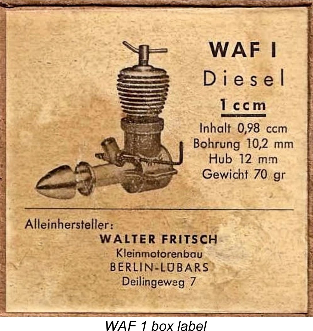
 The design of the WAF 1 is a curious mixture of old and new. Unusually by the date of its introduction, the engine was a long-stroke design having a bore of 10.2 mm and a stroke of 12.0 mm for a calculated displacement of 0.98 cc (0.060 cuin.). As a result, it presented a rather “tall” and perhaps somewhat retrograde appearance. Despite this, its cited weight of 70 gm (2.5 ounces) was by no means excessive for a model diesel of its displacement. The example restored for me by Peter Valicek weighs in at 73 gm - near enough.
  The transfer ports consisted of six steeply-inclined round passages exiting in the substantial inter-exhaust pillars of metal. Oddly enough, these are not formed at a constant diameter but are actually stepped half way along from their lower entry diameter of 2.0 mm to a diameter of only 1.5 mm at their points of discharge into the cylinder. This configuration was presumably aimed at maximizing transfer gas velocity with minimum friction. Clearly Walter Frisch was not a man to cut corners or sidestep a machining challenge!
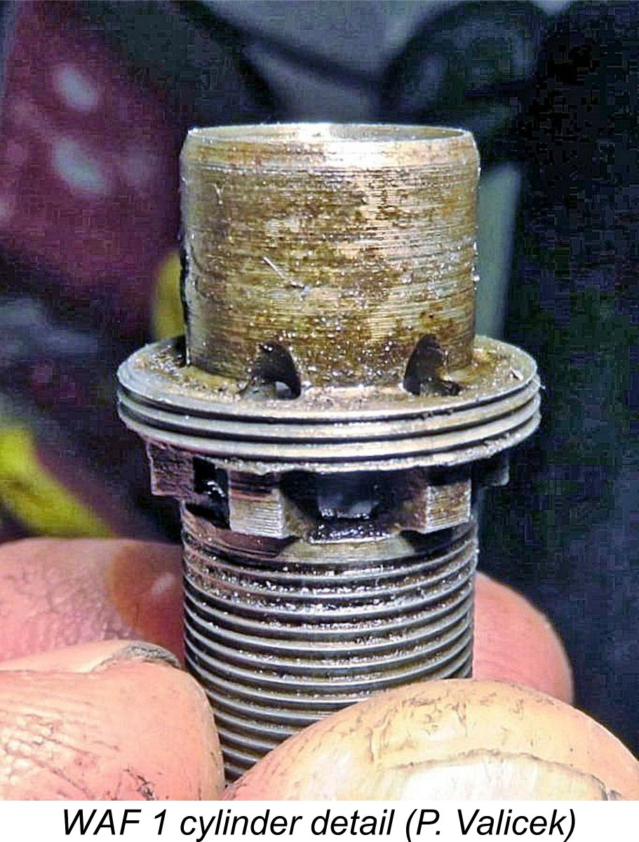 the outer cylinder at transfer port entry level to supply the transfer ports regardless of their position. The system is thus independent of the radial orientation in which the screw-in cylinder ends up.
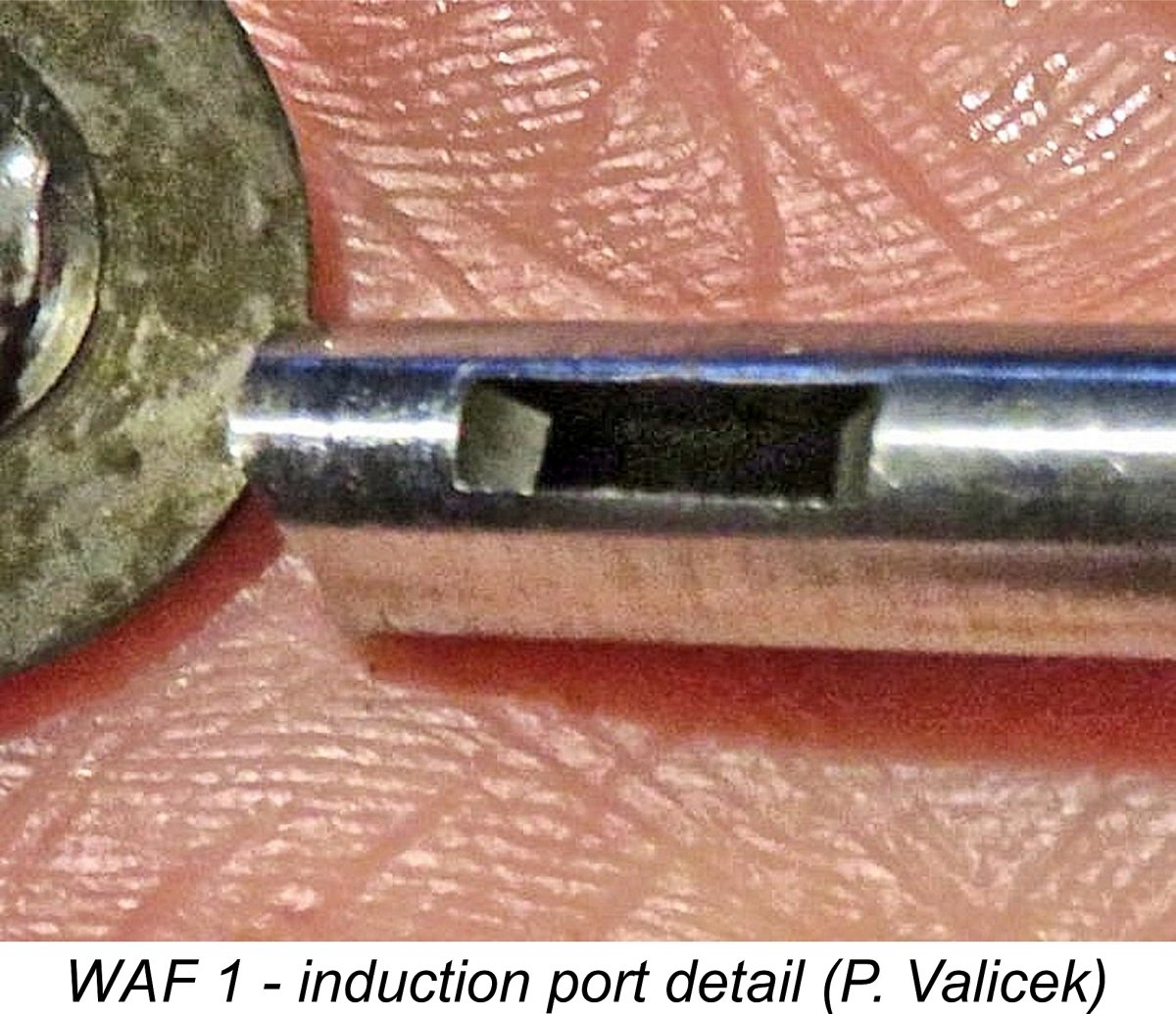
 It appears that as time went by, a few relatively minor changes were made. We already saw that the six bypass flutes which reportedly featured in Peter Chinn's 1953 test example were quickly dropped in favor of complete reliance being placed upon the annular space between the outer cylinder wall and the crankcase interior. This was presumably a cost-cutting measure, although it also resulted in an increase in bypass area.
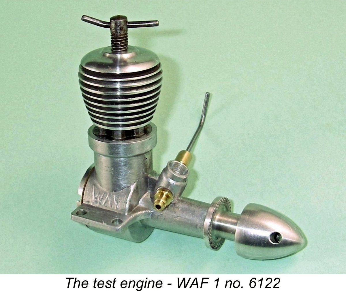
 works would get it running in a few flicks if the settings were anywhere near right!" Very well expressed - once I had established a running setting, the WAF started in one or two lazy flicks every time following a couple of choked flicks. Very reminiscent of the
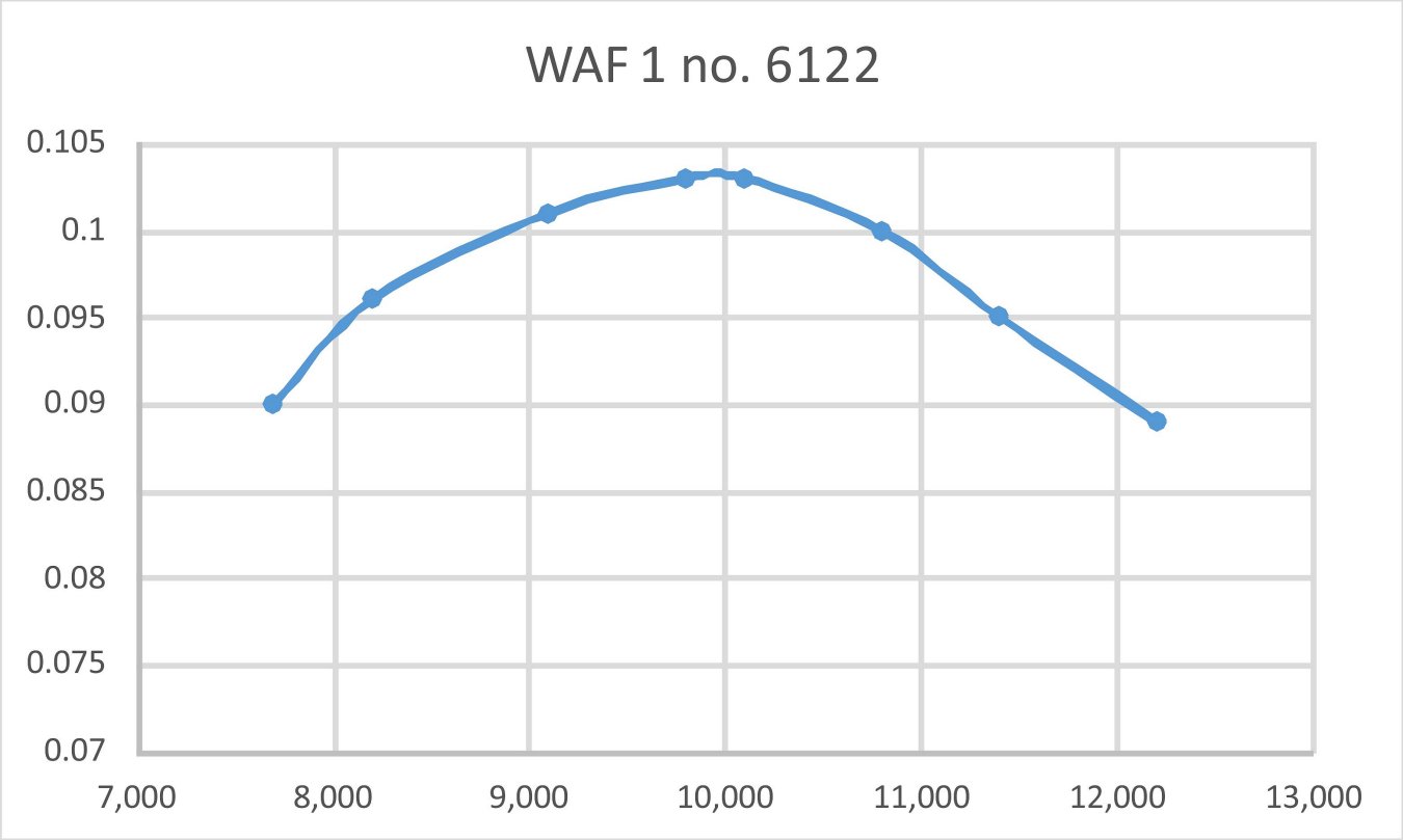
 Indications are that Walter Frisch liked to experiment. We already saw that vacuum pump-equipped R/C examples of the WAF 1 undoubtedly existed, albeit in unknown quantities. The accompanying photo from Tim Dannels' “
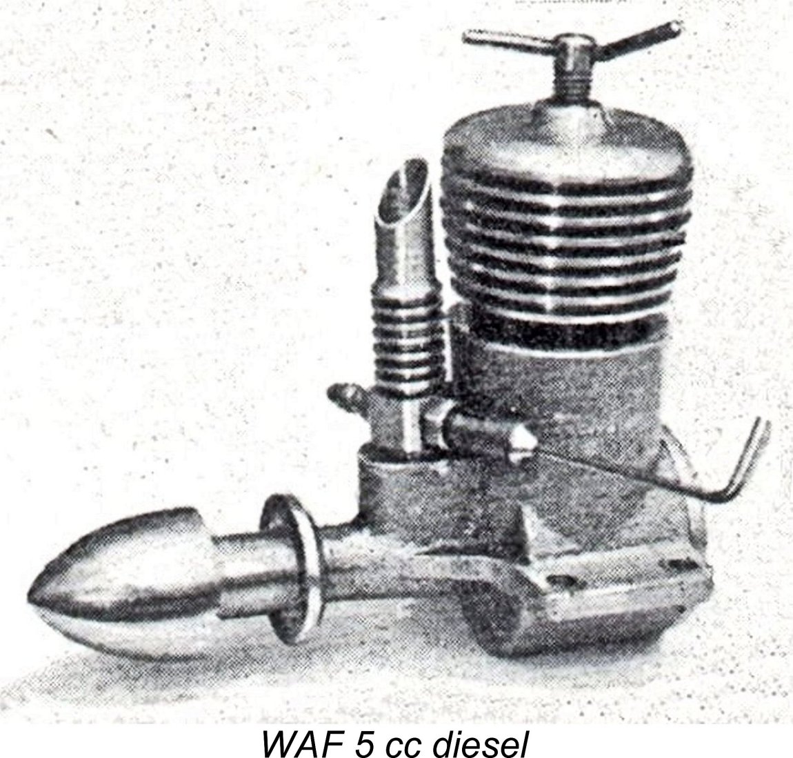 engine, although it is probably a WAF 1. Chinn listed the WAF 1 in his cited table, but also included a WAF 5 cc
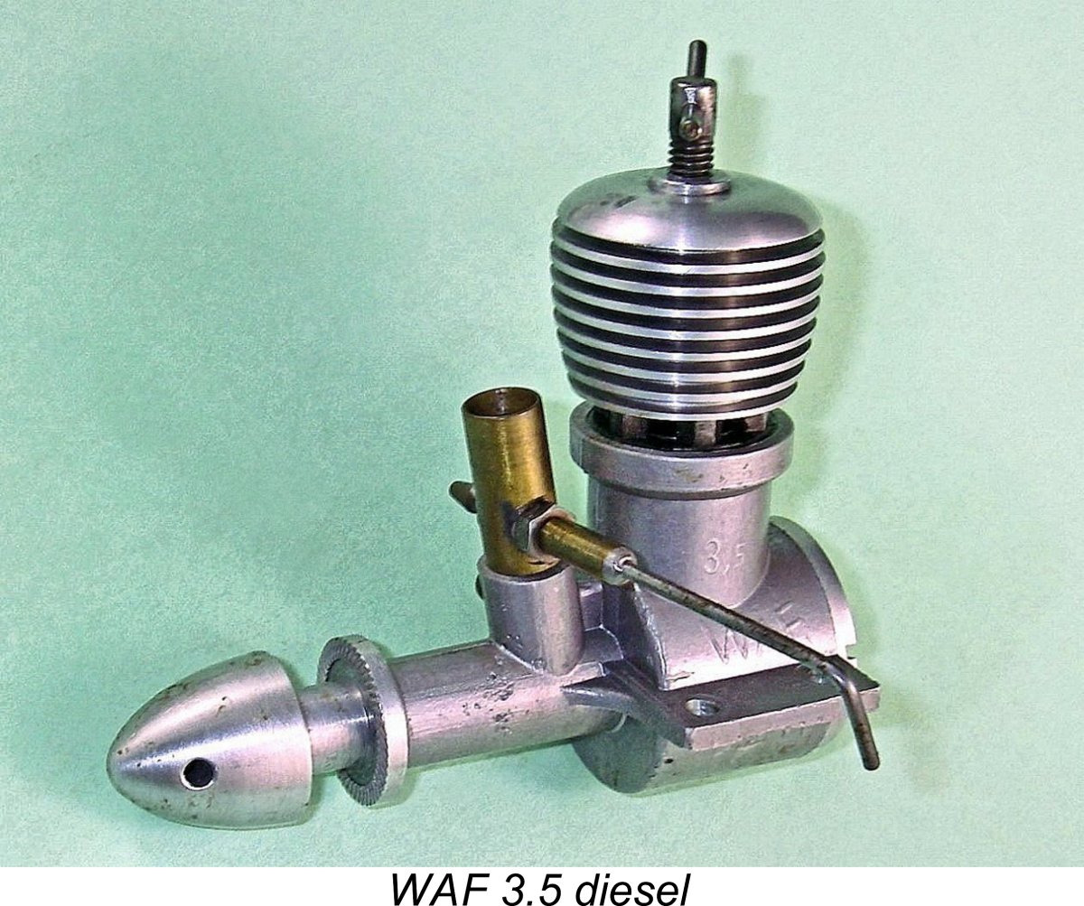
 With its long stroke, I figured that the WAF 3.5 would likely be more about torque at modest operating speeds than all-out top end horsepower. With that assessment in mind, I elected to begin with a 10½x6 APC airscrew. Here I encountered a significant problem - the hub of the WAF 3.5 prop driver has a diameter of no less than 11 mm!! My test set isn't drilled to clear that diameter, forcing me to go on a scrounge among my bloated and very poorly organized prop collection. I was eventually able to provide myself with a small handful of suitable APC props that were drilled out to fit.
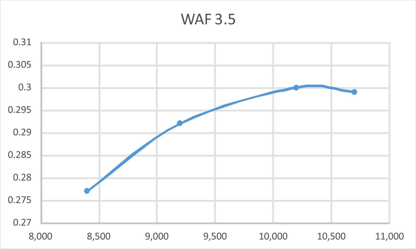
 I’ve so far been unable to track down any authoritative evidence regarding the date of termination of WAF production. The final confirmed media appearance of the WAF engines that I’ve been able to find was the previously-noted reference to the R/C version of the WAF 1 which appeared in Peter Chinn’s “Latest Engine News” column in the April 1958 issue of “Model Aircraft”. In the absence of any accompanying text, the engine's subsequent appearances in the 1963 and 1965 "American Modeller Annual" compilations do not necessarily constitute hard evidence of continuing production, at least in my personal view.
| |