
|
|
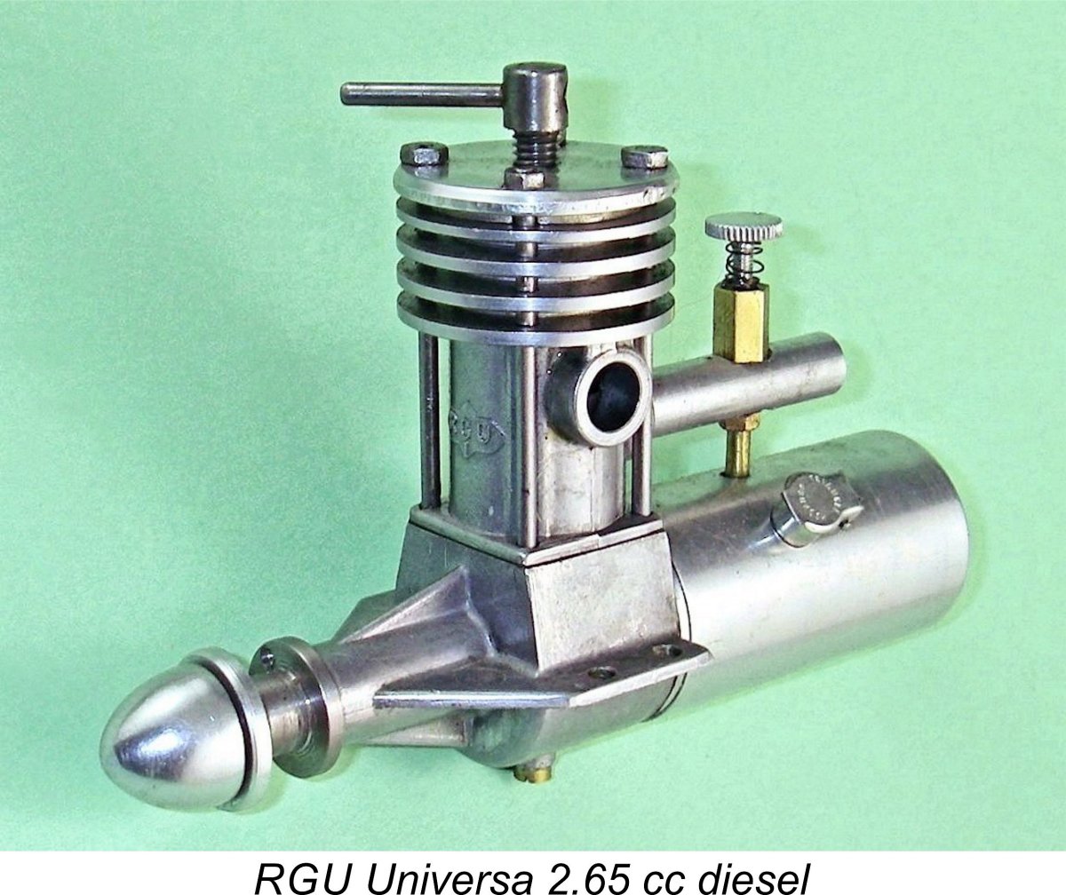
The RGU Universa 2.5 cc Diesel
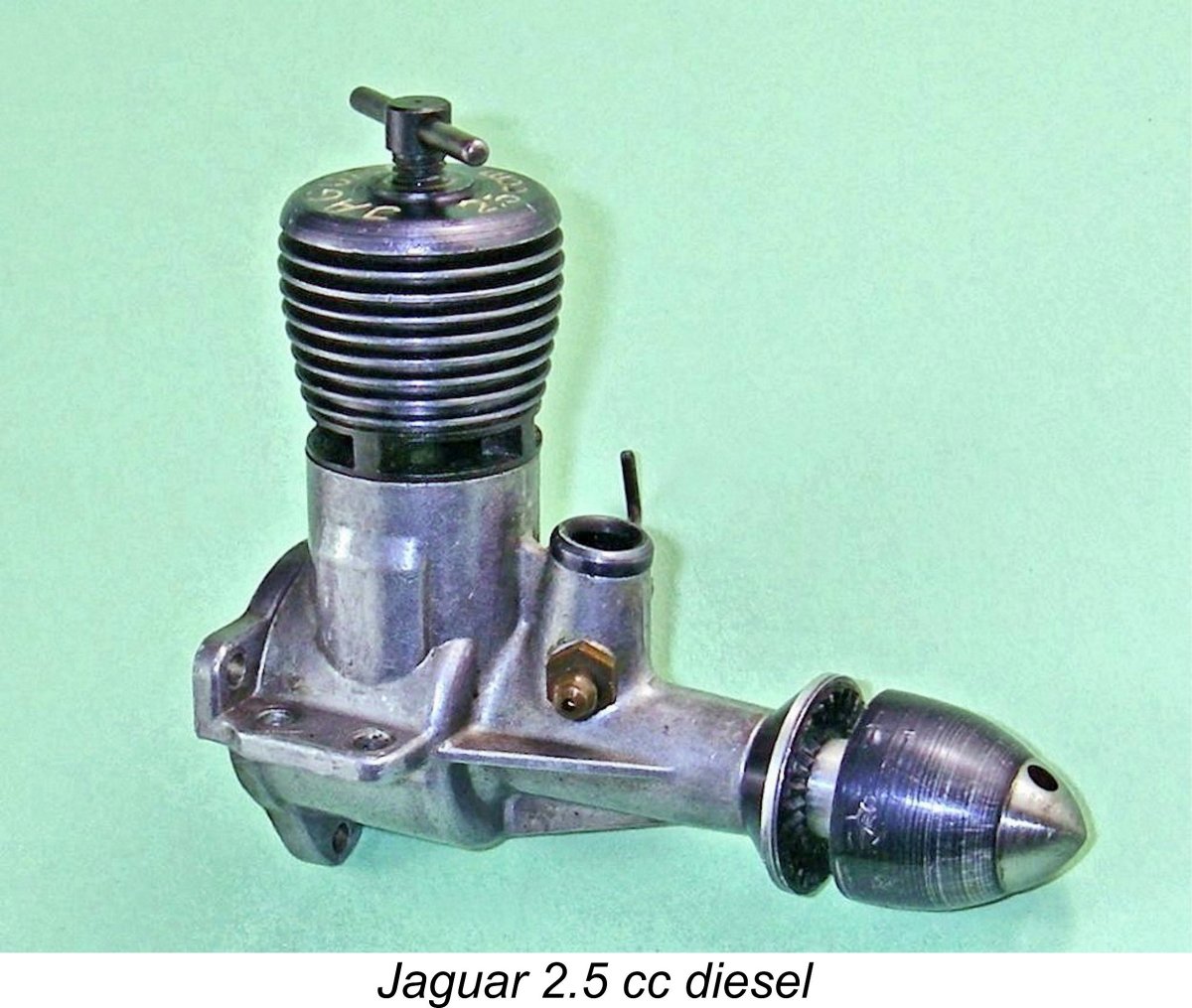
However, what seems to be far less widely appreciated is the fact that the Jaguar engines which began to appear in 1954 were not the first designs with which Rolf Röhner was involved. In fact, Röhner’s initial model engine design was our main subject, the RGU Universa sideport diesel of 2.65 cc displacement. Beginning in 1950, this highly individualistic unit was manufactured in relatively small numbers by Röhner’s original company, Rolf Röhner Apparatebau, also located in Unterreichenbach. Later examples were manufactured by Röhner & Gross prior to being supplanted by the Jaguar range. In this article, I’ll attempt to draw aside the veil which has hitherto obscured the RGU Universa along with a number of other early German products. But before doing so, I’d like to acknowledge the immense contribution made to my research by my greatly valued friend Peter Valicek of the Netherlands. Not only I'd also like to acknowledge the unstinting assistance rendered as always by my late friend and mentor Tim Dannels, publisher of the indispensable "Engine Collector's Journal" (ECJ). Apart from supplying the illustrated example of the engine, Tim was there for me whenever I needed advice or a few images to advance this project. Now, having discharged the pleasant duty of acknowledging those who have assisted me, it's time to embark on yet another of our historical journeys together! To get the ball rolling, some background is required to set the scene. Background
Of course, the enthusiasm of German modellers was by no means diminished by these restrictions – you can regulate peoples’ activities, but not their enthusiasm! Consequently, modelling activity become re-established relatively quickly in Germany following the conclusion of the war, albeit at a somewhat restricted level. A number of new German model engine manufacturers soon emerged, although at the outset they were small-scale operations which were limited to serving only the German domestic market as well as the odd member of the occupying forces. For the most part, their products escaped notice elsewhere, due in significant part to the ongoing restrictions against the participation of German model fliers in International competition. Indeed, it’s likely than the majority of German model engines produced during this period were used in model boats and cars, the operation of which was not restricted.
The early years of the 1950's saw a progressive relaxation of the restrictions upon model aircraft flying in Germany. Established German model engine manufacturers took advantage of this by expanding their ranges, while more new manufacturers soon appeared to meet the consequent increase in the domestic and potential export demand for suitable powerplants. In 1952 the last remaining restriction upon German model aircraft operation was finally removed through the re-admission of Germany to the International competition arena. This led to the country’s rapid re-emergence as a force to be reckoned with in such competitions. Several German competitors showed up at the 1952 World Free Flight Power Championship meeting held in September at Dubendorf Aerodrome in Switzerland. Using then-current Webra 2.46 cc plain bearing diesels, they finished 6th and 7th respectively, thus making a very respectable come-back showing for Germany. The German success in the 1952 World Free Flight Championships naturally awakened a high level of international interest in then-current German engines. This resulted in the publication of the first detailed English-language survey of German model engines of which I'm presently aware. This was a highly informative article by the late Peter Chinn (1921–2005) which appeared as part of Chinn's ongoing “Accent on Power” series in the December 1952 issue of “Model Aircraft” magazine. Today, this long-running series of articles constitutes one of the most invaluable archival records of model engine history from the standpoint of a well-informed and extremely knowledgeable contemporary observer. We are forever indebted to Peter Chinn for preserving so much contemporary information on the model engines of the “classic” and post-classic eras. I routinely refer to Chinn’s work when researching almost all of my own articles, including this one. I often wish that someone would collect all of Chinn’s articles into a searchable DVD or book form………… I’d do it myself if my “Model Aircraft” magazine collection was anywhere near complete. Chinn's December 1952 article was entitled “Engine News from Germany”. As far as I’ve been able to determine, it appears to have been the first detailed post-war English-language survey of German model engine manufacturing activities to be published anywhere. Chinn's article was a praiseworthy attempt to summarize the progress of the various German manufacturers as of the latter part of 1952 following Germany’s then-recent re-admission into the International competition fold.
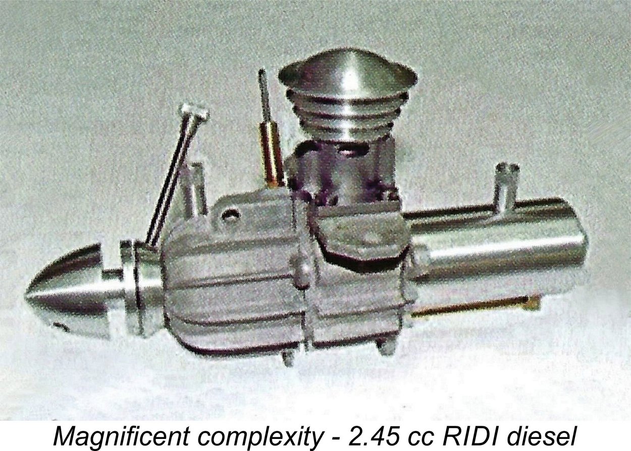
After discussing the BWM engines in some detail, Chinn went on to mention such long-forgotten obscurities as the Kombi-Diesel from Wiesbaden, the Condor-8 glow-plug design from Stuttgart and the RIDI Diesel - an amazingly complex 2.5 cc design which utilized the eccentric bearing system of compression adjustment. See the late Jim Dunkin’s invaluable “Reference Book of .15 ci. / 2.5 cc Model Airplane Engines”, from which the attached image was extracted.
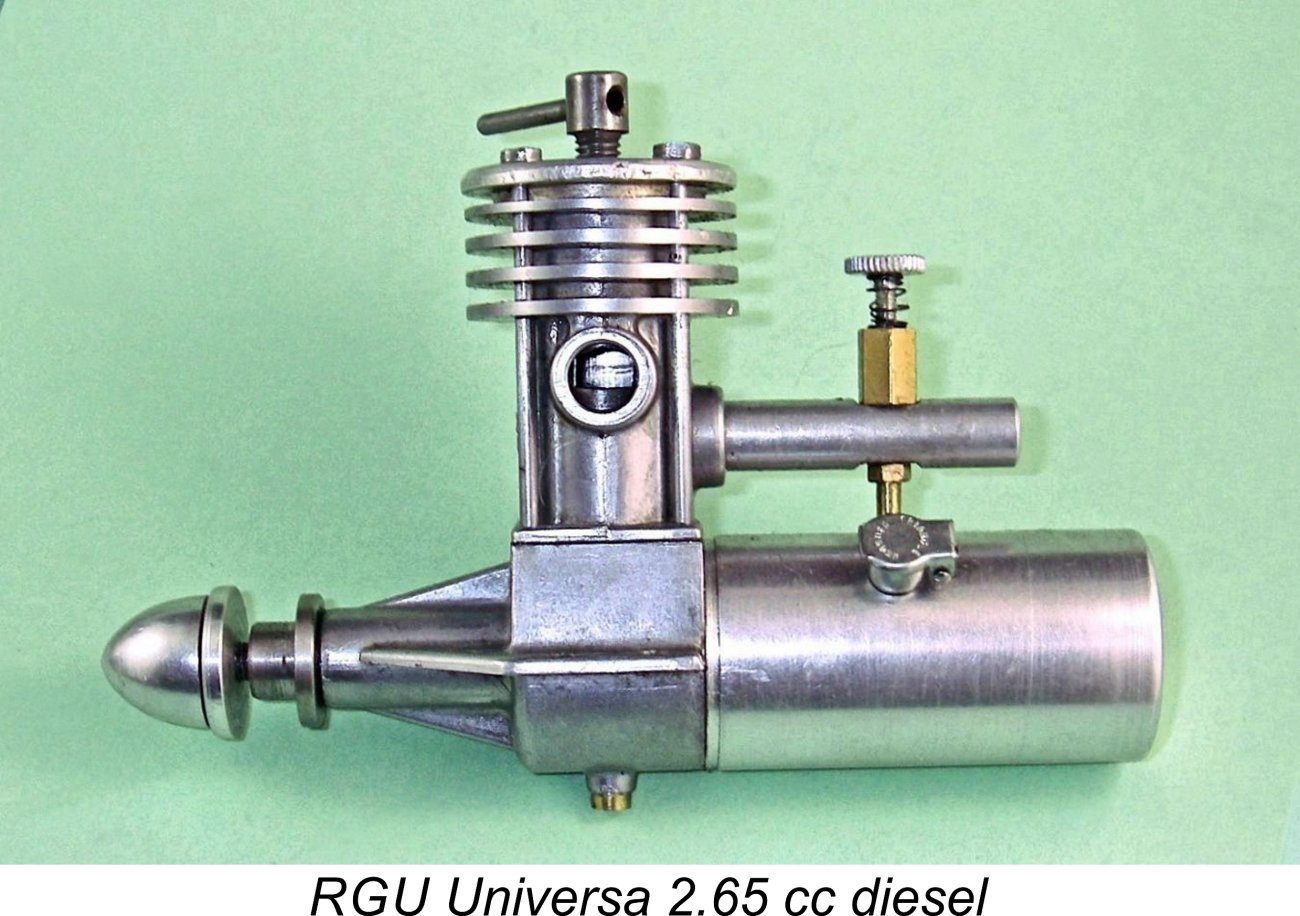
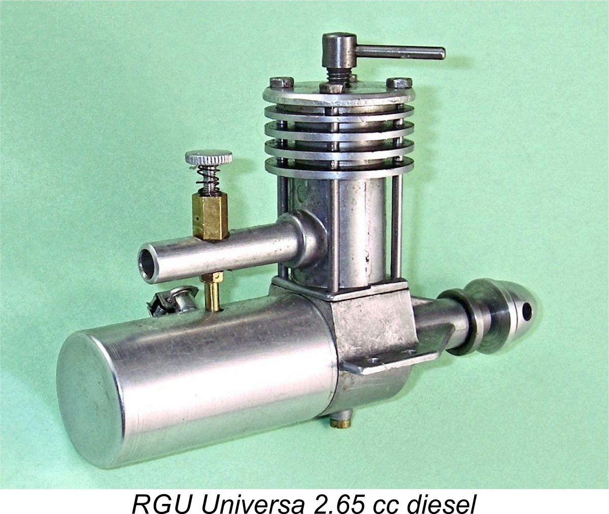
Finally, Chinn also mentioned our subject engine, the RGU Universa, thus conclusively proving that it was in existence as of 1952 rather than the 1953 introductory date which has been given in some sources. Chinn described the RGU Universa as being “a 2.65 cc (15 mm x 15 mm) three-port diesel of slightly traditional appearance” which was “distributed by a Munich firm” (Schmidt). He seems to have had no knowledge of the actual manufacturers of the engine. This is the first mention of the RGU Universa that I can find in the English-language modelling media. It sets the latest possible introductory date of the engine pretty conclusively to mid 1952. Beyond that, a wide range of dates have been suggested. In his well-known and interesting (but often inaccurate) “A-Z” book, Mike Clanford gave an introductory date of 1949 for this engine, without sharing his basis for Faced with this significant discrepancy in dating, I checked with Ronald Valentine, who is one of the world’s authorities on German model engines. Ronald told me that he had a New-In-Box RGU Universa which was still accompanied by its sales receipt dated 1950. It was his understanding that the engine first appeared in that year. My sincere thanks to Ronald for supplying this information, which seems to settle the matter. The engines did not bear serial numbers, making it difficult to provide an authoritative figure for the total number produced. All that can be said is that the engine had a production life of some three years from 1950 to 1953 before being set aside in favour of the far more up-to-date Jaguar designs. Fair enough – we seem to have pretty solid evidence for the identity of the engine’s manufacturer and its date of introduction. What kind of an engine was it?? Let’s have a look ……………….. The RGU Universa – Description As usual, it’s probably best to start with the basics. The RGU Universa is a well-made plain bearing sideport diesel of basically standard late 1940’s design layout. In this respect, it is undoubtedly consistent with Mike Clanford’s suggestion of a 1949 introductory date. This also explains Chinn’s remark with respect to the engine’s “slightly traditional” appearance – fair comment! Chinn was actually understating the case – by 1952 standards (when Chinn was writing), the RGU was unquestionably a throwback to the previous decade.
The RGU is built up around a basic structure consisting of two separate pressure die-castings. The lower of these is the main crankcase with the main bearing cast in unit, while the other (upper) casting incorporates the cylinder barrel, the bypass passages, the single exhaust aperture and the cooling fins. A little unexpectedly, the cooling fins are cast along with the rest of the component rather than being machined into the casting. The only machining carried out on the cooling fins is a light skim of their outer ends to clean them up. The letters “RGU I” are cleanly cast in relief onto the front of the upper casting. The initials RGU presumably stand for Röhner & Gross, Unterreichenbach, although I suppose that they could stand for Röhner & Gross Universa. The Roman numeral I may well reflect the evident fact that this was the first model produced by the company. It also implies that other RGU models may have been in contemplation.
The sole criticism that I can offer with respect to the castings relates not to their quality but rather to one particular design aspect. The mounting lugs appear to me to be cast too thin for complete confidence. It’s true that they are well braced by large webs at the front, but I would still have liked to see a little more metal in them to provide sufficient shear resistance to deal with a hard crash impact as well as to resist potential vibration-induced fatigue failure. The cylinder head is a separate component which is turned from aluminium alloy bar stock. It is centrally drilled and tapped to accommodate a conventional one-armed compression screw. The steel cylinder liner is a tight push fit in the upper cylinder casting. Both the cylinder head and the upper cylinder casting are secured by four long studs which are mounted in tapped holes in the upper face of the lower crankcase casting. The two components slip onto the four studs and are then secured using nuts at the top of the s Both the piston and contra-piston are of cast iron. The piston construction is highly unusual – the gudgeon (wrist) pin is supported in bosses which are actually produced separately from the piston itself. The bosses take the form of two substantial tubular sections which are brazed into oversized holes in the piston walls prior to final machining of the piston exterior and lapping the piston into the bore. This construction allows the piston to be turned both inside and out while providing more than ample gudgeon pin bearing length in the piston bosses. The downside is that the resulting piston is unusually heavy at all of 15 gm. It drives the crankshaft through a sturdy-looking forged alloy conrod.
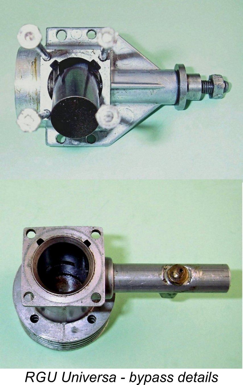
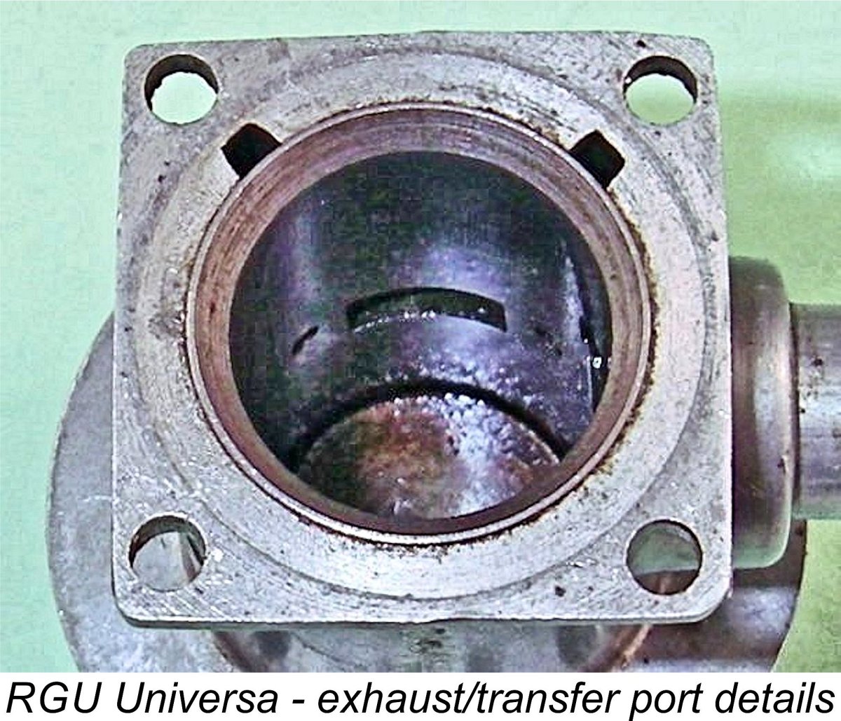
The really interesting design feature of this engine is found in the bypass and transfer arrangements. Looking first at the unusually small twin bypass passages, these are necessarily divided vertically into two sections by the presence of the split at the top of the lower crankcase. Looking at the deck of that lower component, we find a pair of small rectangular cutaways which are positioned on either side of the exhaust location. These cutaways are continued as long narrow slots formed in the interior wall of the upper casting. Adequate material to The bypass slots in the upper casting are of course separated from the bore by the presence of the lower cylinder liner. To transfer mixture from the bypass slots to the actual cylinder, two remarkably small holes are drilled horizontally through the liner at the slot locations on either side of the exhaust port to serve as transfer ports. These ports will direct incoming mixture in the opposite direction to that of any escaping exhaust gasses. I have to say that this is by far the most restrictive bypass and transfer system that I’ve ever encountered in an engine of this displacement! In terms of its port timing, the engine is fairly conventional. The exhaust opens a little earlier than we might expect at around 110 degrees after top dead centre (ATDC) for a total exhaust period of some 140 degrees. The transfers open considerably later at around 130 degrees ATDC for a fairly lengthy blow-down period of 20 degrees and a relatively short total transfer period of some 100 degrees. The induction port opens at 45 degrees before top dead centre (BTDC) for a total induction period of 90 degrees – a pretty standard figure. There is no supplementary sub-piston induction. The most notable design parameter which emerges from the above survey is the unusually small area of the bypass passages and transfer ports. We might look for some kind of logic in connection with these features. The first thing that comes to mind is that the very small bypass volume will h The other highly unusual feature of the design is the actual location and direction of the transfer ports. Being simple round holes which are located on either side of the exhaust port, these will discharge incoming transfer gas directly away from the exhaust port – a very clear expression of the reverse flow scavenging principle. The relatively long blow-down period coupled with the comparatively low operating speed that might be expected from this design should cause much of the exhaust gas movement towards the exhaust port to have dissipated prior to the opening of the transfer ports. The arrangement will thus result in two high-speed jets of transfer gas being directed away from the exhaust port into a cylinder having very low residual gas pressure. We might expect loss of incoming mixture through short-circuiting into the exhaust port to be relatively minimal - most of the gas displaced by the incoming mixture will be spent exhaust gas. The other benefit of promoting high transfer gas velocities is that this has a strong tendency to improve starting characteristics. Looked at in this way, the porting arrangements and associated timing have a certain logical consistency for an engine that may be expected to be at its best at relatively low speeds. Even so, one wouldn't expect the use of this very restrictive bypass/transfer system to release much in the way of peak power output. Another potential downside to the use of very small bypass and transfer ports is that we might anticipate more than the usual amount of difficulty in clearing a flooded crankcase, something to which sideport diesels are rather prone in any case. The designer clearly recognized this issue, since the engine is provided with a screw-in drain plug at the base of the main crankcase. I could see this being a very useful feature. Having dealt with the RGU’s unusual porting arrangements, the rest of the description is pretty straightforward. The engine utilizes a one-piece steel crankshaft having a plain crank disc with no counterbalance. Given the relatively heavy piston, I’d expect vibration levels to be fairly high, with optimal operating speeds being relatively low in consequence. The fit of the shaft in its bearing is outstanding.
The prop is secured in place by an aluminium alloy spinner nut which engages with an M5x0.8 thread at the front of the shaft. The prop driver has no knurling whatsoever to prevent prop slippage. In combination with a spinner nut (as opposed to a conventional nut and washer), this will likely prove adequate, also doing something to protect the shaft by allowing for some slippage in the event of a crash impact. There is however a small blind hole in the face of the prop driver into which one could place a small ball bearing or stud prior to tightening the prop. With a prop having some “give” (or provided with a matching blind hole), this would provide pretty good anti-slippage insurance if desired. At the rear, the engine features a screw-in backplate having an unusually long shoulder behind the sealing face. It is provided with a pair of holes at the rear to allow for removal and re-tightening using a pin spanner. The intake is a straight length of extruded aluminium alloy tubing. The single-jet brass spraybar has an extended hexagonal length on the top (needle) end, while the fuel pickup end is threaded 3 mm. Thespraybar is secured in position with a brass nut, while the brass fuel pickup tube which extends down into the The RGU's final wrinkle is its seemingly excessively large fuel tank which rather overwhelms the rest of the engine – I reckon that the engine looks far better proportioned without it! This component is stamped from thin aluminium alloy. It is not secured in any way by any mechanical fastener – instead, it is a moderate push fit over the machined outside diameter of the long backplate shoulder. Amazingly enough, this arrangement appears to leak very little if at all. The tank is prevented from slipping rearwards by the brass fuel pickup tube. It is equipped with a German equivalent of a Gits cap. The engines were supplied with an unusually comprehensive German-language instruction manual. New owners were provided with excellent directions to help them get to grips with diesel operation. So much for a description of this interesting engine. Next question – how does it run? I’m as keen as you to find out, so let’s head for the test bench! The RGU Universa on Test By the time that the RGU Universa appeared, it was almost alone in sticking with the classic sideport design – all of its contemporaries apart from the smaller Mills models and the E.D. 2 cc units had adopted rotary valve induction of one sort or another. This being the case, I decided just to go ahead and evaluate this engine on its own merits without placing my usual emphasis on comparisons with contemporary designs.
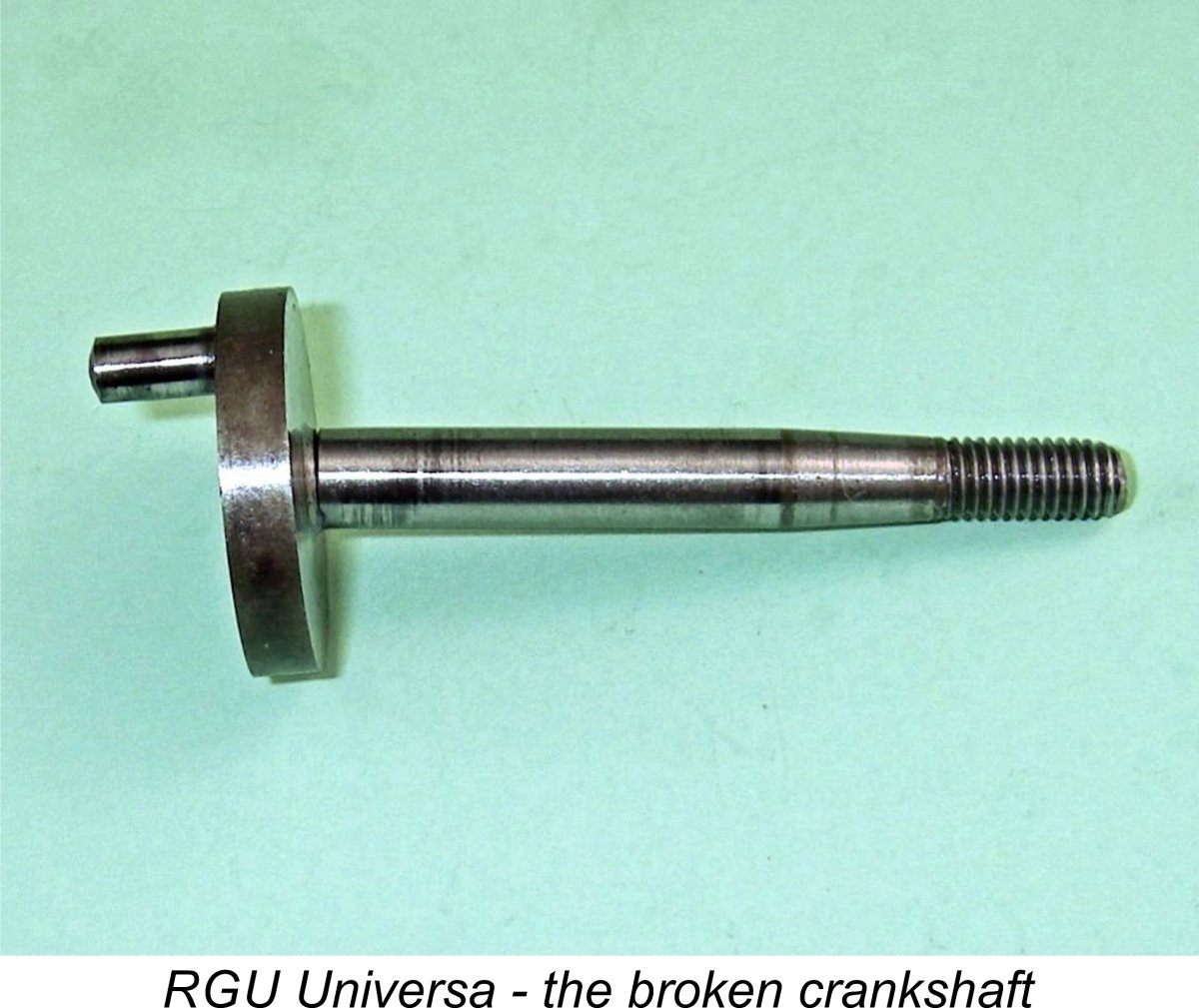
The first problem that I encountered was the fact that the engine felt a little “odd” when turned over by hand. Investigation revealed that the crankshaft was cracked immediately forward of the crank disc! Thankfully, I have a very good friend in the form of Peter Valicek of the Netherlands. Peter is an outstanding machinist as well as being a great supporter of my work on engine history. He agreed to make a new shaft for the engine, also making a beautiful new tank to replace a badly damaged original component. While he was at it, Peter considered a number of possible causes of the failure. Among the chief of these was the engine’s unusually high reciprocating mass coupled with an absence of crankweb counterbalancing. The piston alone was found to weigh 15 gm - far above the average for a 2.5 cc engine. The total reciprocating weight (piston, rod, wrist pin) was found to be no less than 22 gm. Such a reciprocating mass would put very high cyclic stresses on the crankpin and crankshaft during operation.
With the RGU expertly restored by Peter and returned to Canada, I was in a position to try again. However, there was a cautionary note in this context. During his own testing, Peter had observed that the engine was rather prone to detonation. If this condition had been experienced during earlier runs, it would go far towards explaining the shaft failure due to the high shock loadings which detonation imposes. The very unusual transfer arrangements may have contributed to this. Being forewarned about this issue, I resolved to pay particular attention to any evidence of its occurrence during my own testing. To minimize the possibility, I decided that I would use an un-nitrated fuel consisting of equal parts of ether, kerosene and castor oil. Between them, the oil and kerosene should do much to tame the tendency of the ether to detonate. I will admit to having chickened out on conducting this test for a while, being really concerned regarding the possibility of undoing Peter's fine work as a result of the detonation problem. But in the end, I succumbed to curiosity - there was no point at all in leaving the beautifully-restored engine on the shelf and thereby wasting Peter's outstanding efforts. So full steam ahead - if it broke, it broke .................
I found that the best approach was to administer no more than 2 choked flicks to draw fuel up from the tank to the intake and then administer a small exhaust prime. After that was done, one or two flicks invariably resulted in a start. Despite the smooth face of the prop driver, I experienced no problems with prop slippage at any time. Once running, I found that response to the controls was extremely good. The needle in particular was delightfully non-critical - the sweet spot was well defined but was by no means a hairline setting. The optimum compression setting was also very well defined. Both controls held their settings perfectly at all speeds tested. Vibration was certainly present, but not at levels which would give rise to undue concern. Peter's efforts doubtless have much to do with that - I'm sure that vibration would be far more of an issue with an unmodified example of the engine. The excellent control response made it very easy to find the best combination of compression and fuel mixture. Once set, the engine ran very smoothly and steadily, with no sign of detonation at any time and a nice clear honey-coloured exhaust residue stream with little smoke, indicating good combustion characteristics. I suspect that the fuel that Peter was using may have contributed to his detonation troubles with the same engine. So far, it all sounds wonderful, doesn't it?? Well, now we get to the fly in the ointment - the engine simply doesn't develop a lot of power! The following test figures tell the story.
As can be seen, the application of established power absorption coefficients to the measured prop/rpm figures yielded a nice smooth curve. The implied peak output was around 0.088 BHP @ 5,700 rpm. This is about equal to an E.D. Mk. II but at a somewhat lower speed. It's also reasonably close to the measured performance of the Majesco 2.2 cc diesel tested earlier. However, it falls well short of measured figures for both the Micro Diesel and the C.I.E. 10 from America. All of these are sideport models of generally similar displacement and layout, so they represent a fair comparison. That having been said, it's important to remember that the test engine was by no means in stock configuration. With its significantly lighter piston and counterbalanced crankweb, we would expect it to perform better than an unmodified example. This underscores the very low performance potential of the basic design. The primary cuprit here must surely be those ridiculously small bypass passages. It would appear that the engine was basically asphyxiated by its own transfer system. Frankly speaking, the rationale for that design continues to elude me .............
Another design feature which defies logic is the unnecessarily and awkwardly oversized fuel tank. One really has to wonder what drove the decsion to use such a tank! The engine seems to run forever on a fill - certainly far too long for free flight service. The fact that it's not transparent means that you can't use the old eyeball fuel measuring trick, besides which its length would definitely result in incomplete consumption of the contents - tip the model back ten degrees in a climbing attitude, and a good portion of the fuel will pool at the rear beyond the reach of the fuel pickup. A transparent hang tank would have been a far more suitable design choice. Anywy, now we know! Anyone planning to run one of these engines should pay particular attention to its reported potential for detonation and should temper his performance expectations! I'd suggest that a 10x7 or 11x5 wood prop would be very suitable choices for bench testing. I'd also strongly recommend the use of an un-nitrated fuel - at these speeds, you don't have to worry about ignition lag! Conclusion I'm afraid that this review has raised as many questions as it has provided answers! Given the issues encountered and the performance figures extracted, the rationale for this engine's appearance in 1950 is difficult to discern. Moreover, the thinking behind some of its design features is similarly obscure. Still, an interesting look at a well-made and user-friendly engine which nonetheless challenges us on a number of levels. Without such units cropping up now and then, wouldn't life be boring?!? Accept and enjoy!! _____________________________ Article © Adrian C. Duncan, Coquitlam, British Columbia, Canada First published January 2020 |
||
 Many model engine aficionados are familiar with the Jaguar engines which were produced during the 1950's in Unterreichenbach, a town in the Black Forest region of West Germany, by a firm called Röhner & Gross. The designer of these excellent engines was Rolf Röhner. They were marketed by Josef Friedrich Schmidt of Munich. Schmidt has often been cited as the manufacturer of the Jaguar engines, although in reality he was only their distributor.
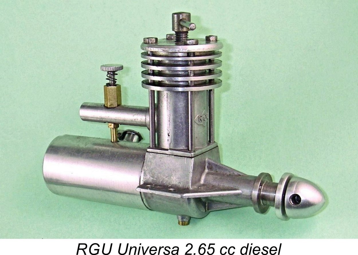
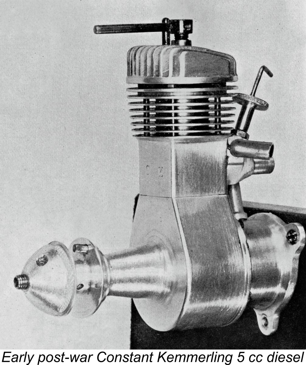 The RGU Universa is one of a number of early post-WW2 German model engine designs which never really came to the attention of either the modelling community or the modelling media outside of Germany. The relative obscurity of many of these early post-war German products such as the magnificent Constant Kemmerling 5 cc diesel pictured here may be explained in large part by the fact that for some years following the conclusion of that conflict, model flying activities in Germany had been severely curtailed by the occupying powers. This had undoubtedly applied the brakes to the development of German modelling technology as well as restricting the visibility of German modelling activities to the rest of the world.
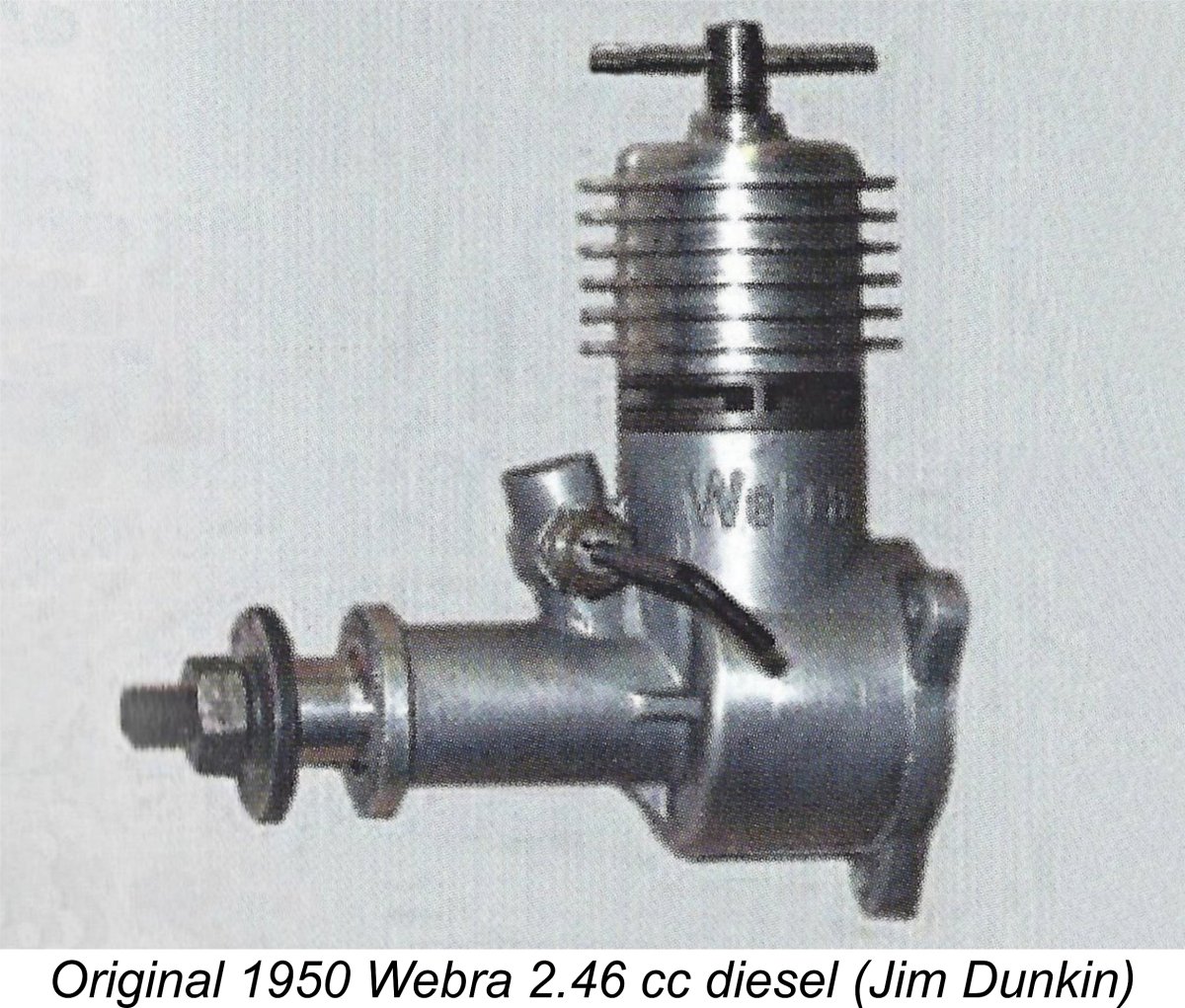
 At the time when Chinn was writing, the soon-to-be-famous
  A very interesting omission from Chinn’s article is any mention of Hans Hörnlein’s Taifun range which had first appeared in 1950. Given the rapid rate at which this range was developed from 1950 onwards, this omission is hard to explain. Chinn did however mention several East German manufacturers who were then operating behind the Iron Curtain, including the
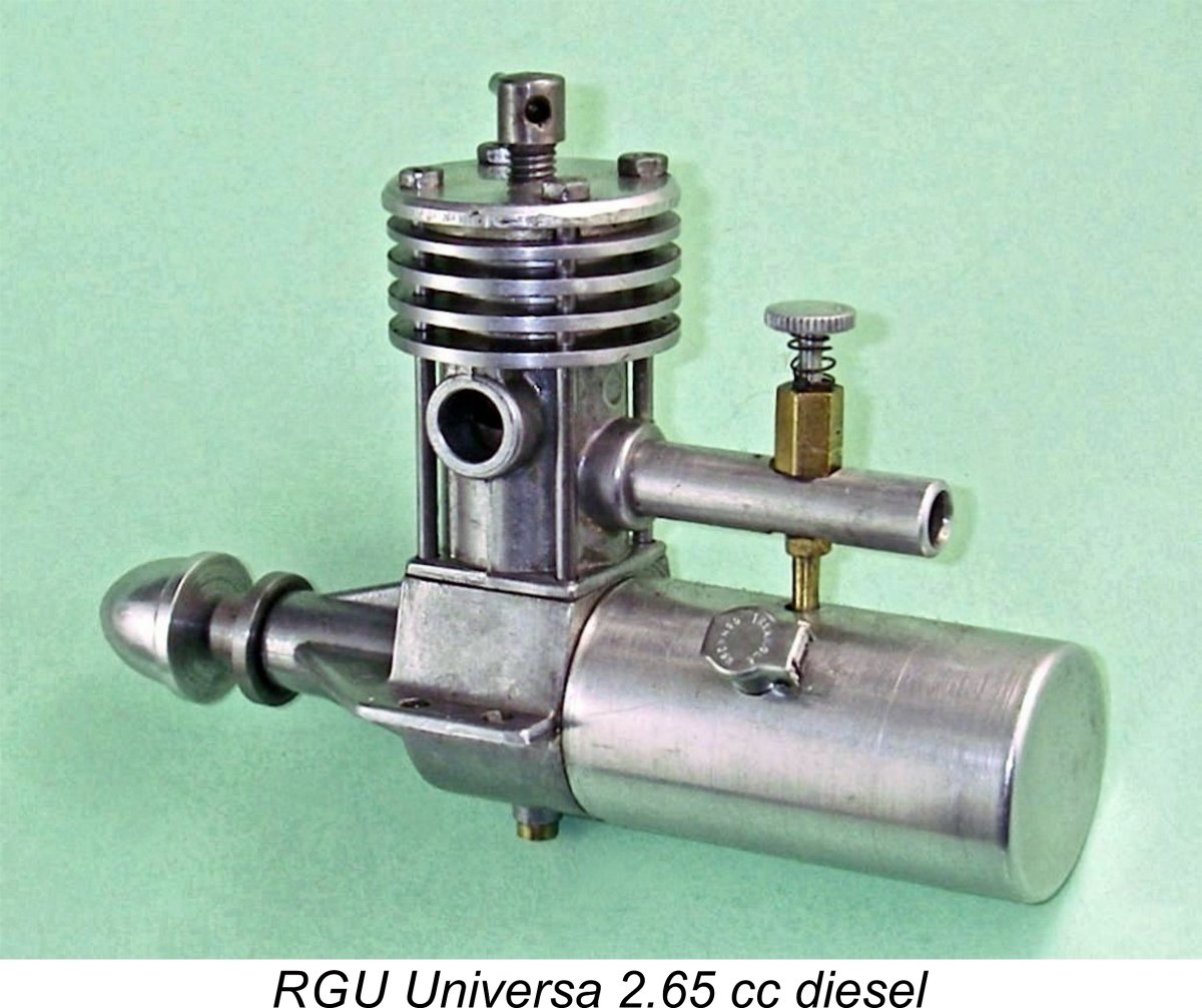
 The main area in which the RGU departs from the 1940’s sideport design tradition is in its internal geometry. Checked bore and stroke are 15 mm (0.590 in.) apiece for a calculated displacement of 2.65 cc. These “square” dimensions represent a departure from the more usual long-stroke measurements generally applied to engines of this type. The engine weighs a fairly hefty 197 gm (6.95 ounces) complete with tank.
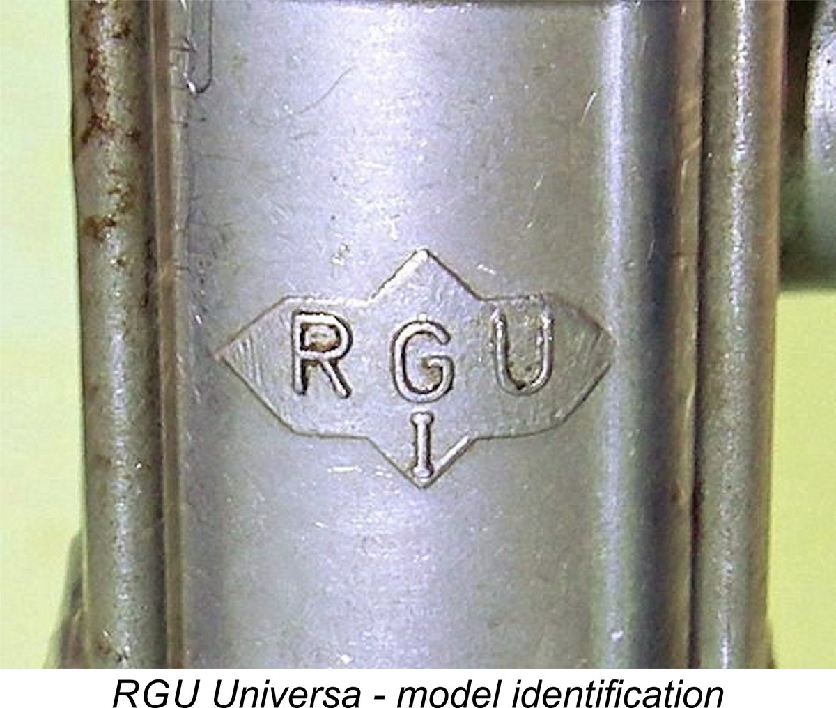 The use of pressure die-casting is interesting insofar as Peter Chinn’s previously-mentioned December 1952 article included a comment from the contemporary German distributors of the Webra range to the effect that die-casting technology in Germany up to 1952 had apparently lagged behind that of other countries such as England. Problems had evidently been experienced in bringing the die-castings used in the Webra engines up to the required standard, although Chinn reported that he could find no basis for complaint in the sole Webra product that he had examined up to that point in time. I can add my own comment with respect to the RGU Universa – the standard of pressure die-casting exhibited in my example leaves little to be desired.
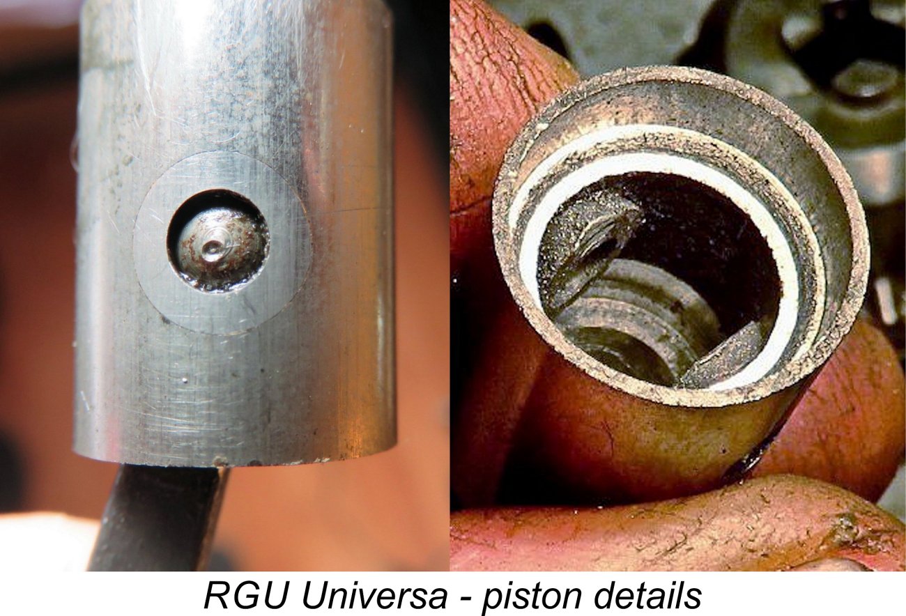
 The steel prop driver is secured on a very shallow (approximately 7 degree) self-locking taper. It has the not-uncommon Continental hub diameter of 10 mm, which is annoyingly just over the 0.375 in. diameter for which my standard test props are all drilled (I use sleeves to adjust for engines having smaller diameter hubs). I would therefore have to scrounge to find a few props that would fit for testing purposes.
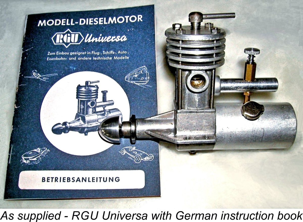
 Having recently embarked upon a testing program of old spark ignition motors, I had accumulated a set of calibrated wood props of appropriate sizes for this test. I bored out a handful of duplicates to fit and was all set.
 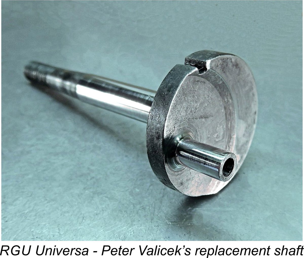 By careful machining of the piston, Peter was able to get the total reciprocating weight down to 16 gm - still pretty substantial, but a big improvement which should both reduce the operating stresses on the shaft and minimize vibration to the extent possible. To further improve matters, Peter incorporated a degree of counterbalance into the crankweb of the replacement shaft.
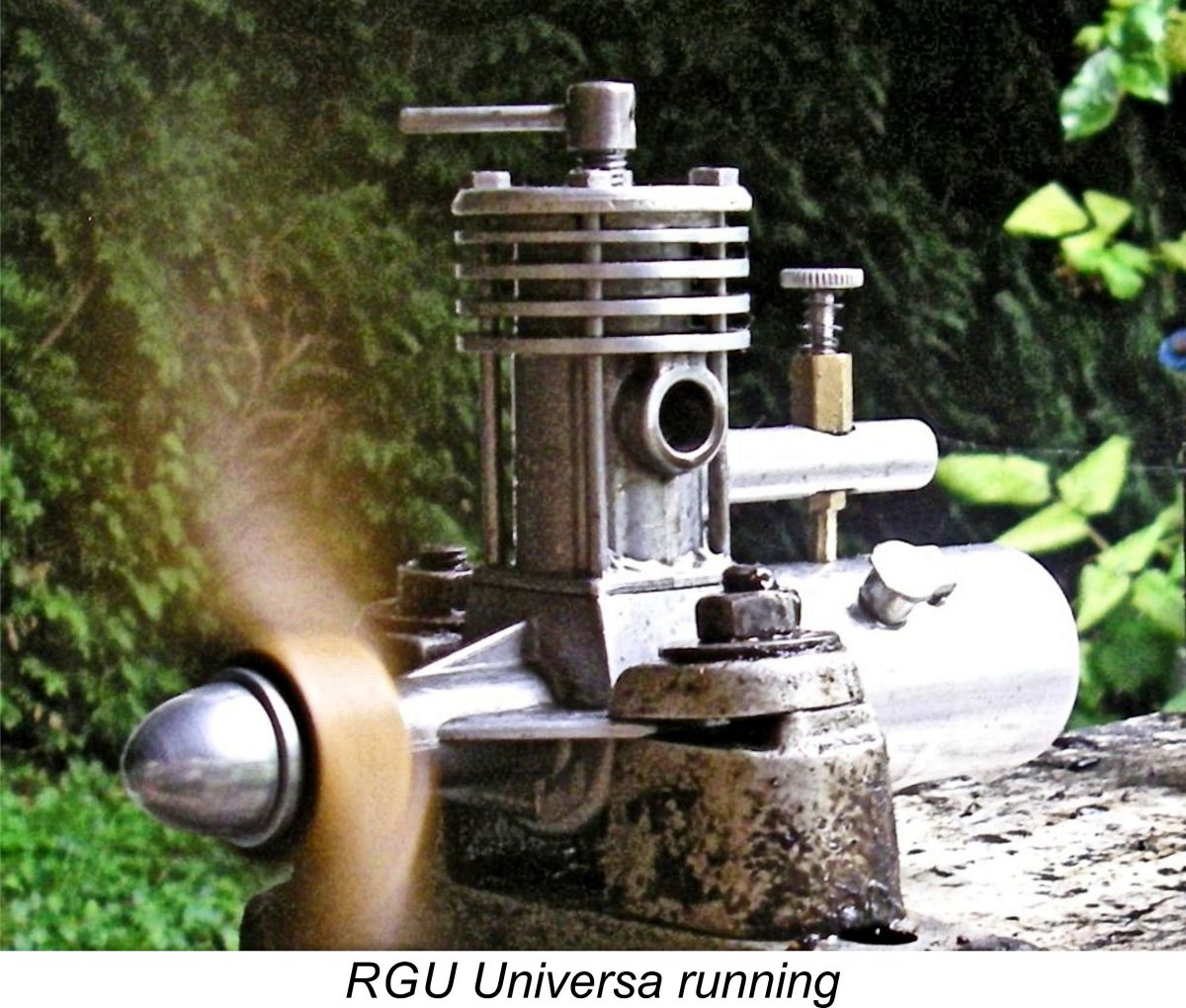 As it turned out, I needn't have worried! Once set up in the test stand with an 11x7 wood prop fitted, the engine proved to be an instant starter using the low-test fuel mix mentioned earlier. The one oddity for a sideport unit was that it needed a small prime to start - all that finger-choking accomplished was to flood the crankcase. One can see why that drain screw was incorporated at the bottom of the case! No doubt the unusual bypass arrangements have something to do with this characteristic, since they would definitely impede the transfer of fuel from the crankcase to the upper cylinder.
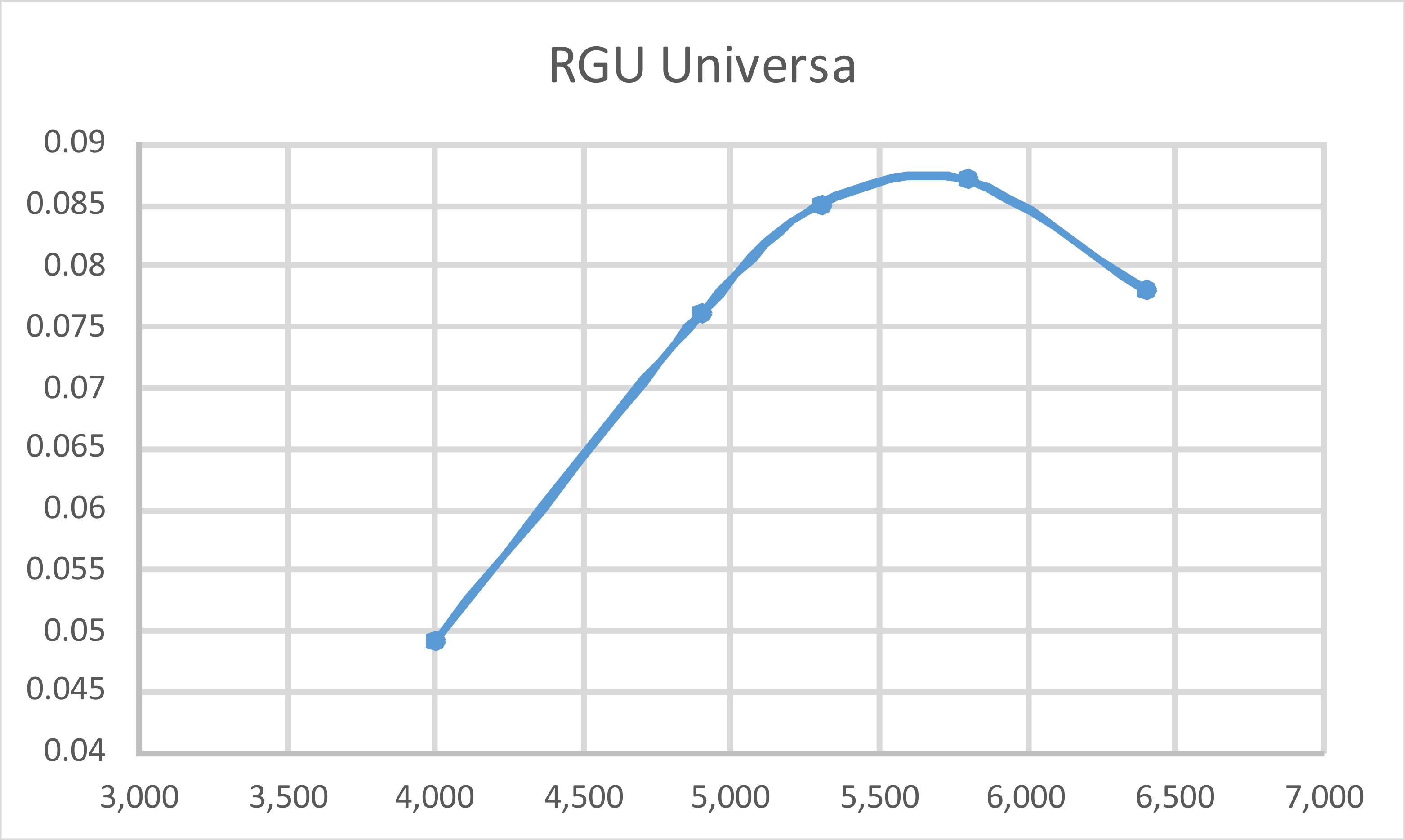
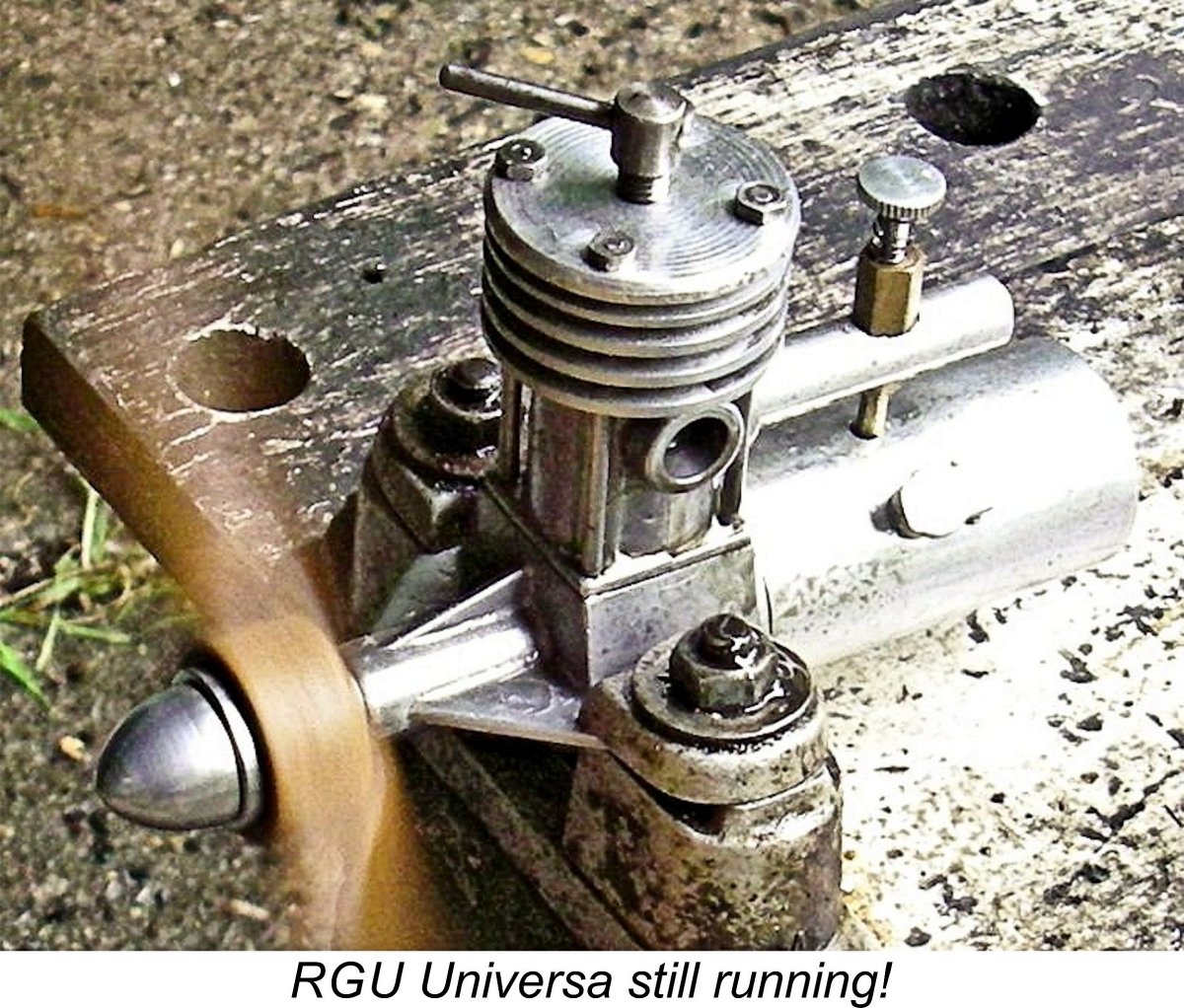 Indeed, the measured level of performance actually leaves me wondering why this engine was released at all in 1950! As noted earlier, almost all competing manufacturers had moved beyond sideport induction by that time, and accepted standards of performance were way above that achieved by the RGU. True, the engine was a well-made and seemingly user-friendly sports motor which would have done fine in a sport free-flight model provided one used the appropriate fuel to discourage detonation. However, it would have fallen well short of meeting the performance standards required for control line service, especially considering the engine's weight.
 | |