
|
|
A Tale of Two Mels - the Melcraft Engines
The reader might already be asking why I would pick out the Melcraft from among the myriad .29 cuin. spark ignition models which became widely available in America during the early post-war period before the late 1947 advent of the miniature glow-plug swept the sparkies (and the diesels) aside. The simple answer is that it presented a number of design features which set it well apart from the rest, at least in my personal view. Although a fairly conventional side-port design at heart, it featured a front intake along with an unusually-routed induction passage. The manufacturers claimed that this represented a form of “supercharging” and incoming mixture "pre-heating" which purportedly gave the engine a performance advantage. Such statements always arouse my suspicions - just how justified were they in making these claims?!? Only one way to find out .......... Whenever my curiosity is aroused, I tend to jump straight into an investigation of the engine in question, particularly if I have one on hand as in this instance. But before subjecting the Melcraft to this scrutiny, there are a few acknowledgements to be made. First, I wish to pay tribute to my greatly valued late friend and mentor in all things American, the incomparable Tim Dannels, AMA Model Aviation Hall of Fame member and publisher of both the “Engine Collector’s Journal” (ECJ) and the “American Model Engine Encyclopedia” (AMEE). Tim made a great start on the preservation of the Melcraft story with the publication of his original article on the engine in issue no. 107 (October 1993) of ECJ. In that article, Tim asked readers to supply information on examples in their possession. The reader response was sufficiently prompt and enthusiastic that Tim was soon able to compile a detailed chart recording the serial numbers of over 30 reported examples along with their individual characteristics. This work was presented in issue no. 108 (December 1993) of ECJ. It provided a great deal of clarification regarding the finer details which were successively featured in the engine. It would be extremely difficult to assemble this information from scratch today, underscoring the immense contribution to the preservation of model engine history which Tim made through the creation and maintenance of the hard-copy (and hence permanent) record represented by ECJ. He left shoes which will never be filled. However, none of Tim’s earlier work included any substantial information regarding either the company which made the engines or the individuals associated with the venture. That task fell to ECJ reader Ron Carlson, whose persistence and enthusiasm led him to track down a number of those directly involved. This enabled Ron to write a full account of the background to the Melcraft venture. Ron’s wonderfully informative article appeared in issue no. 135 (August 1999) of ECJ. Without Ron’s timely efforts, much of the history of the Melcraft engines would have been irretrievably lost forever. We are very much in his debt. I freely acknowledge my reliance upon the above references when preparing this article. I’m also most grateful to my late mate Tim Dannels for pointing me to these sources. Now, having given due credit where it’s due, it’s time to get down to the task at hand. First, some background …………… Background
Mel Schmidt was born in 1915. He became interested in power modelling during its rapid rise to popularity in the pioneering era of the 1930’s. After leaving school, he went to work for Dr. O. W. Lohr, Director of the Central Laboratories at 537 Millard Street in Saginaw, preparing tissue samples for the medical profession using specialized equipment that he designed and built himself. Mel maintained his interest in modelling throughout this period. By the final years of the 1930’s his interest had become focused upon the engines that powered these models. To provide an outlet for the design ideas that he was beginning to formulate, Mel set up a small machine shop in his parents’ basement at 1928 Monroe Street in Saginaw. There he began to construct his own engines, beginning in 1939 at the age of 24 years.
In Mel's own recollection, around 200 examples of this design were built and sold locally. One wonders where they are now .............. Although designed and constructed by Mel Schmidt, this was not a true Melcraft product because the design was completed and production initiated prior to the establishment of the partnership with Mel Bluemlein. Meanwhile, the other Mel (Mel Bluemlein) was working at the S&E (Sutton & Edel) machine shop just outside of town on Junction Road near Dixie Highway. As a sideline, he also ran a small hobby shop out of his parents’ basement on South 9th Street in Saginaw. Given Mel Schmidt’s active involvement with models and model engines, it was inevitable that the two would become acquainted. It's very likely that Mel Bluemlein sold the other Mel's "clamp bypass" model through his basement store. The two Mels soon acquired a high level of respect for each others’ machining abilities. In 1941 they decided to join forces, quitting their jobs and establishing a new company both to provide general machining services and to construct and market the engines developed by Mel Schmidt. The new venture was called Melcraft Machine & Motors Co. It operated initially from rented premises at 1505 Janes Avenue in Saginaw. The intervention of WW2 beginning in December 1941 as far as the USA was concerned naturally had a dampening effect upon any plans for further model engine development - indeed, model engine production pretty much ground to a halt as the necessary materials were re-directed to military purposes. The partners did manage to produce a few more examples of Mel Schmidt’s 1941 "clamp bypass" design mentioned earlier, but that was about it. Presumably they supported themselves by undertaking machine shop projects in support of the war effort, but there’s no surviving record of this. The Janes Avenue premises didn’t remain available for long. In 1943 the landlady decided that she had had enough of the noise emanating both from the shop machinery and the engines themselves while being tested. By 1944 the business had been relocated to 809 East Genesee Street. This downtown Saginaw location combined sufficient space and commercial potential that the partners were able to operate a hobby shop at the front, with the machine shop at the rear.
It was clear that the forthcoming post-war competition among model engine manufacturers would be pretty fierce. This being the case, the partners reasoned that it would take a new design with some promotable special features to give them an edge in the coming sales race.
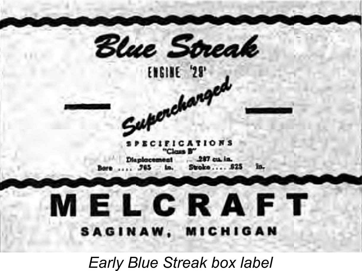
The initial advertisement for the Melcraft 29 by that name appeared in the December 1945 issue of "Model Airplane News" (MAN). This advertisement is reproduced at the right. It highlighted the claim that the Melcraft was "super-charged", citing the engine's potential for setting "startling new performance records". The selling price was given as $18.50 - a fair chunk of change for a .29 cuin. non-racing engine in those days. Someone commented that on the basis of the supercharging feature, the models which the engine powered should go “like a blue streak”! This very quickly prompled a change of name from just plain Melcraft 29 to the Blue Streak 29. The design of the engine was unaltered by this action. As matters transpired, this was an unfortunate choice of name. It turned out that a Texas company which made two-cycle dieselengines had previously copyrighted the Blue Streak name! The Melcraft boys soon received a letter from the Production of the engine continued more or less unchanged - only the advertised name was changed back to the Melcraft 29. Oddly enough, the International Tool Corporation of Chula Vista, California, makers of the Ira Hassad-designed Bluestreak 65, used that name in 1948 without being challenged. Perhaps the Texas company’s copyright had expired …………. or perhaps the combination of the two words into a single term got around the copyright. The two Mels were clearly very talented machinists and toolmakers. They made most of the tooling in-house, even down to the taps and dies required to cut the threads for the crankcase and backplate. They also made the casting dies, Using this equipment, they cast their own crankcases, backplates and timer frames as well as lower body pans for a tethered race car that they produced later (see below). They also cast speed pans for control line model aircraft. Another very successful product was a die-cast alloy control line handle which was sold by the thousands through National Model Distributors of Chicago. Returning to the Melcraft engines themselves, the dies used to cast the early crankcases featured knock-out pins to aid extraction from the die, but the castings were found to be so easily extracted that these knock-out pins were progressively dropped. The dies did undergo a few minor modifications to deal with wear issues and also to improve the appearance of the engines, but in practical terms the design remained essentially unchanged throughout despite the changes of name. At the outset, Austin Craft universal needle valve assemblies were fitted to the engines. However, the company eventually began making these items themselves, producing them in quantities far exceeding their own needs. Both rigid and flexible needle controls were variously fitted. Thousands of these assemblies were sold through National Model Distributors as universal components.
It’s an interesting observation that there appears to have been a relationship of some kind between the two Mels and their fellow Michigan-based model engine manufacturer Wilfred “Fred” Gibbs Orr. The Orr Tornado 65 racing engine was manufactured in distant Niles, Michigan at the other end of the State, although it was marketed out of Lansing, Michigan, which is far closer to Saginaw. The Melcraft car was specifically designed to accommodate the Orr 65, as witness a number of surviving photographs. It’s also undeniably true that the basic design of the Orr Tornado bore a striking general similarity to the previously-mentioned 3 horsepower bicycle engine that Mel Schmidt had constructed in 1941! A full review and test of the Orr 65 appears elsewhere on this website.
Sales of the Melcraft 29 had continued throughout the period just described. The engines were shipped in sturdy and attractively-labelled cardboard boxes supplied by the American Paper Box Co. of Court Street, Saginaw. The early boxes were blue, in keeping with the engine’s early Blue Streak name, but following the name change back to the Melcraft 29 the boxes too were changed to a striking yellow and brown color combination.
Production of the Melcraft 29 seemingly ended in late 1947 immediately following the commencement of the glow-plug revolution instigated by Ray Arden’s November 1947 introduction of the commercial miniature glow plug. American modellers and manufacturers alike instantly gravitated en masse to the new form of ignition, effectively ending the spark ignition era overnight and also dousing the fires of what had looked like becoming a highly productive American involvement wih model compression ignition ("diesel") engines. It's clear that the two Mels recognized this immediately, hence seeing no future for the Melcraft 29. It’s a bit of a puzzle why they chose to step aside rather than develop a glow-plug model, perhaps using rotary valve induction, with which they could compete in the new marketplace. However, there’s no evidence that they ever so much as contemplated doing so. Despite their departure from the model engine manufacturing field, Melcraft continued in business, offering a range of accessories such as their very popular control line handles. However, the demand for these products also fell off over time, leading the two partners to finally wind up the Melcraft venture in 1951 after a ten-year run in business. Mel Schmidt had a simple explanation for this, stating that “with the introduction of national television, we found out that kids couldn’t build models and watch television at the same time!”. Shades of our own times, when the general addiction to push-button wireless technology has virtually killed off modelling as a craft-based activity. They'll never know what they're missing ..........and perhaps they're OK with that. Following the winding up of the company, Joe Dallaire of Detroit, Michigan ended up with most of the finished inventory. The balance of the residual assets (boxes, casting dies, tooling, car tyres, rough castings, stampings, etc.) were either scrapped or went to the dump. Sad ……….. At the time when Ron Carlson was conducting his research during the late 1990’s, Mel Schmidt was still alive and well in his early ‘80’s and still living in Saginaw. Mel Bluemlein passed away in 1970, and Mel Schmidt has since joined him. Now that we’ve reviewed the history of the Melcraft venture, it’s time to take a look at the engines themselves. It has generally been reported that three distinct models of the Melcraft 29 were produced. In terms of the finer details this is true, but the reality is that the changes between these variants were very minor. Many of them simply represented changes in production procedures rather than any significant re-design of the engine. In functional terms, the Melcraft remained essentially unchanged throughout. That said, the three normally-distinguished variants may be summarized as follows: Blue Streak 29 - 1945
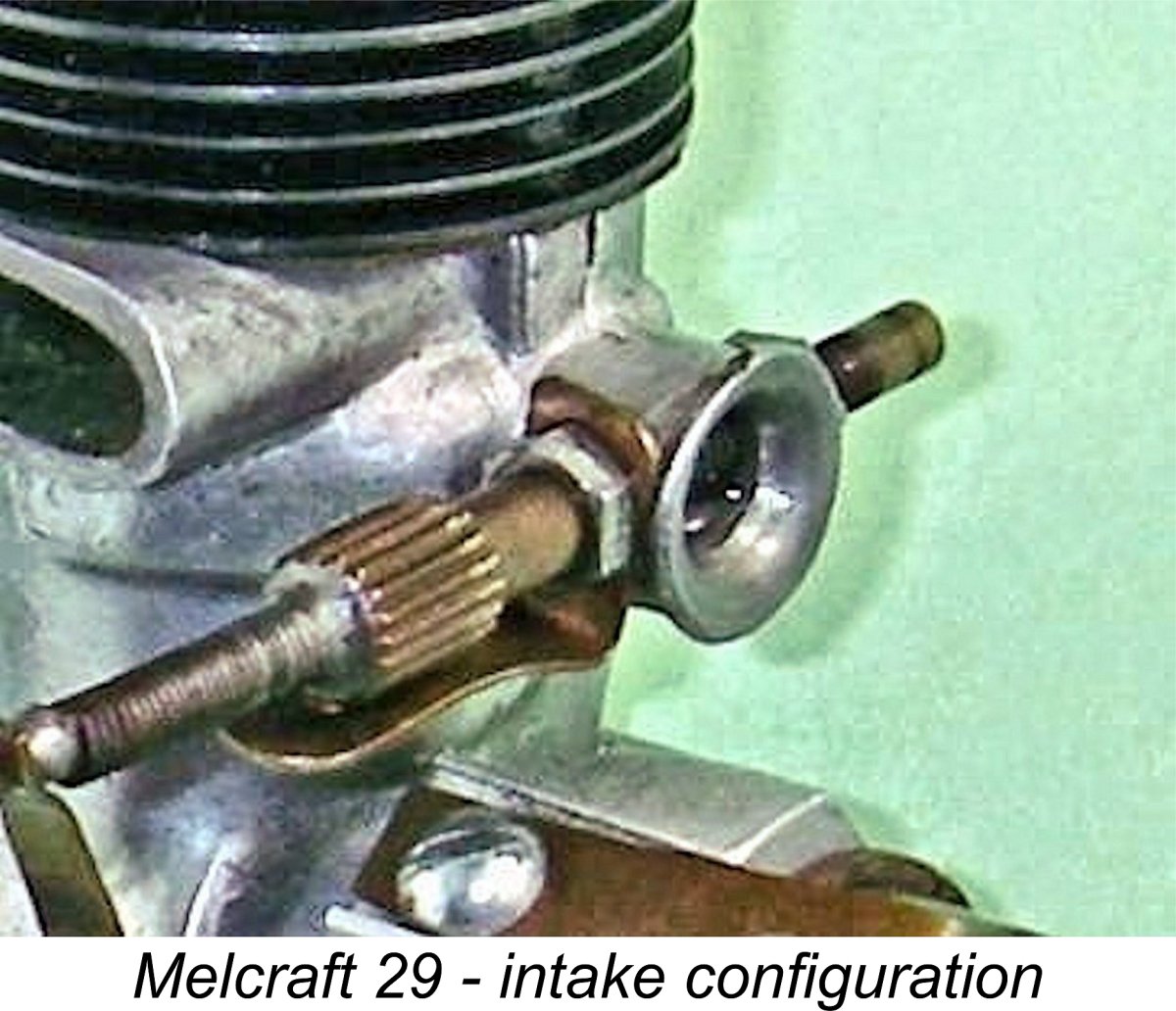
In common with its successors, the actual displacement of this engine was .287 cuin. (4.71 cc), derived from a bore of 0.7651 in. (19.43 mm) and a stroke of 0.625 in. (15.87 mm). The engine is notable for its unusually short stroke by normal side-port standards. Cited weight was a relatively light 5½ ounces (156 gm). The Blue Streak was built around a permold crankcase having the side-port intake venturi at the front where it was wide open to the effect of the engine's slipstream. This was the basis for the manufacturers' claim that the engine was "super-charged". Such an arrangement might lead us to expect that the cylinder’s induction port would also be at the front. However, things were more complicated than that! The piston-controlled induction port cut into the cylinder wall To supply this unusually oriented and very wide port, the incoming mixture was routed through an integrally-cast annular passage formed internally in the upper crankcase. This led incoming mixture around the exhaust side of the upper crankcase to supply the previously-described 120 degree cylinder induction port along its entire length. The "bulge" which accommodates this annular passage is clearly visible just beneath the exhaust stack in many of the attached images. A very similar arrangement had been used previously in the short-lived APEX 45 of 1936, although in that case a rear entry was employed. This was quite an ingenious design, the one downside being that the system relied entirely upon a very precise fit of the lower cylinder in the crankcase given the impossibility of providing a gasket between the induction and exhaust ports. The lower crankcase seal was completely dependent upon a close metal-to-metal fit along the very narrow strip of metal separating the induction and exhaust ports. I have to admit that the crankcase compression in my example is beyond reproach - well done, the two Mels! The cylinder is actually a moderate push fit in the upper crankcase.
In other respects, the engine was conventionally ported, employing cross-flow loop scavenging with a generously-proportioned bypass passage and a cast iron baffle piston. The cylinder and head were machined from steel in one piece, with a blind bore. This is not the best arrangement from a performance point of view, since no provision can be created in the underside of the cylinder head to accommodate the upstanding baffle at top dead centre. Hence the baffle establishes the minimum possible spacing between the lower surface of the cylinder head and the piston crown. This both limits the compression ratio and enforces a very inefficient combustion chamber which creates no swirl and is divided by the baffle at top dead centre. Direct volumetric measurements taken from my own example show that the compression ratio was a very modest 6.5 to 1. The design would almost certainly prevent a higher figure from being created. Given this very low ratio, it comes as no surprise to learn that the manufacturers' recommended fuel was a blend of 3 parts white gas to 1 part of SAE 70 mineral oil. Effective operation on methanol would require a somewhat higher compression ratio. The combination of a low compression ratio and a very inefficient combustion chamber naturally leads one to the expectation that this would not be a high-speed engine despite its very well-developed cylinder porting arrangements. The cylinder was secured to the crankcase with two long screws. The piston drove the steel crankshaft through a steel conrod having an Oilite bronze bushing at the big end. The main bearing was provided with a similar bushing. The crankweb was heavily counterbalanced, while the shaft was centrally drilled for lightness. The casting finish applied to this and the following model varied from a natural as-cast surface to matte gray. A short exhaust stack was featured, with its outer end being cut parallel to the engine’s axis. The generously-proportioned flat-surfaced bypass bore several large knock-out marks near the top. A knockout mark also appeared beneath the exhaust stack on the induction "bulge". A short rigid universal needle valve was used on this model. The spraybar diameter of 0.125 in. (3.175 mm) combined with a 0.250 in. (6.35 mm) diameter venturi throat formed a combination which would not be expected to create good low-speed suction with a 4.7 cc engine. Plugging these numbers into Maris Dislers' choke area calculator confirmed these suspicions, at least in theory - below around 6,000 rpm, suction would be expected to be marginal and needle response somewhat uncertain. Something to evaluate on test - see below.
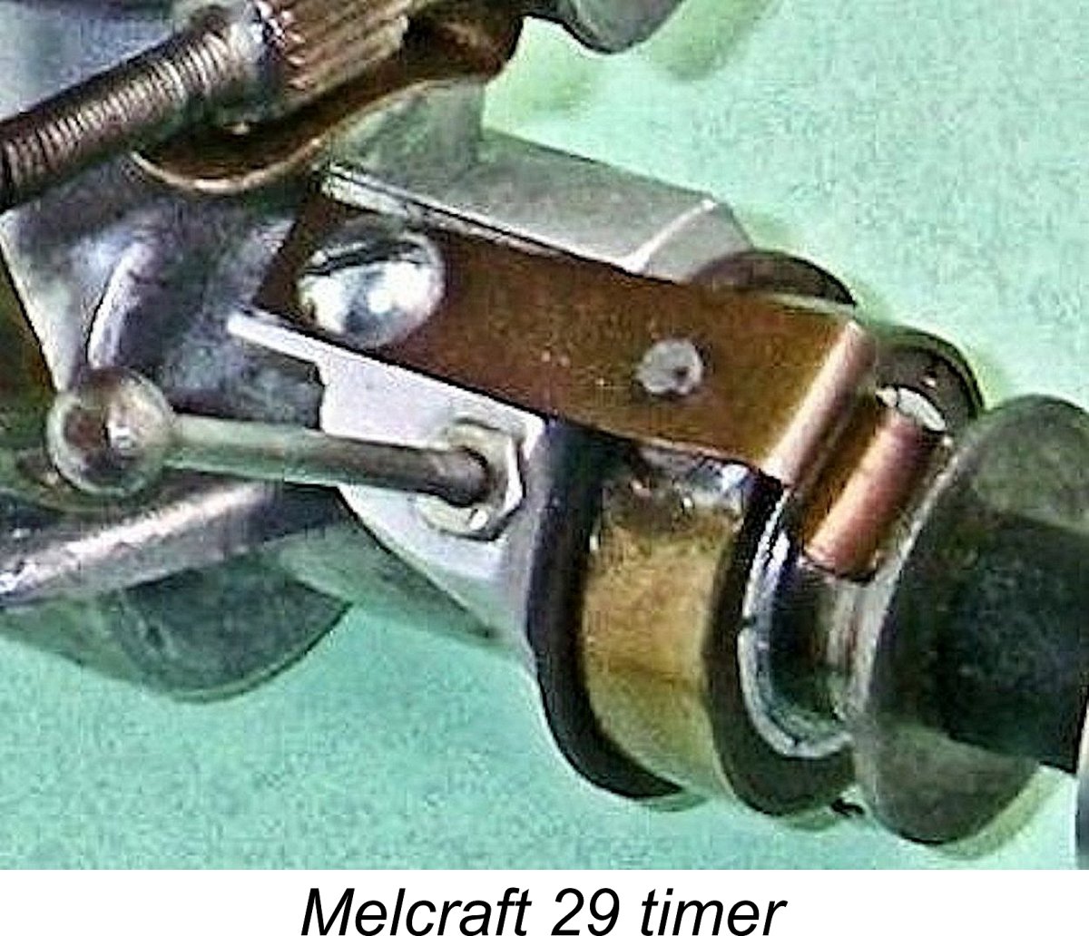
When describing a spark ignition engine, an important additional parameter which needs to be quantified is the dwell period provided by the engine’s timer. This is the angle of crankshaft rotation during which the points are closed and hence in direct electrical contact with each other, thus supplying current to the coil's primary circuit. I discussed this parameter more fully in my separate article on spark ignition operation to be found elsewhere on this website. Since sufficient real time must be provided during each revolution to ensure full saturation of the primary coil winding and its associated magnetic field before the points open to trigger the spark, the dwell requirement varies from engine to engine, the main governing factor being operating speed. A slow-speed unit like a Brown Junior, Atom .099, Bunch, Elf or even an early Ohlsson can operate successfully with a relatively short dwell period of 50 – 60 degrees or even less. A short dwell period both conserves the life of the flight batteries and reduces thermal stress on the coil, since it minimizes the proportion of running time during which the points are closed and current is flowing to the coil from the batteries. However, it also makes the engine more susceptible to ignition problems caused by point "float" - an inertia-induced delay in the points following the cam surface during closure, thus further reducing the effective dwell period. In addition, it limits the maximum speed at which the engine can be run because at higher speeds there's insufficient real time for the coil to become electro-magnetically saturated, as it needs to be to provide a good hot spark. This causes a misfire to creep in which cannot be eliminated using the controls. In effect, the timer becomes an electronic rev limiter. Even so, since a short dwell period means that flight battery life should be well conserved and coil temperatures minimized, the use of the shortest dwell period that will work at the engine's design operating speed is well warranted. In the case of the Melcraft, direct measurement confirms that the dwell period provided by the timer is of the order of only 40 degrees. Such an unusually short dwell period suggests that the engine was not expected to operate at high speeds, seemingly contradicting the 10,000 rpm peaking speed reportedly claimed by the manufacturers (see below). There's little doubt that a significantly longer dwell period would be required to achieve smooth running at such speeds. Compounding this issue, the tension of the flat leaf spring that closes the points is relatively low, further reinforcing the impression that this timer would not be expected to deliver a reliable spark at the higher speeds. Although the moving point assembly is very light and the gap is quite narrow, I’d still expect point float to become an issue at higher speeds, further reducing the already very short dwell period. I’d be truly amazed if this timer would support the 10,000 rpm speed reportedly claimed by the manufacturers. It was likely this factor that led to the addition of a second spring to the timer used on the third variant to be described below in its place. The cam may also have been reconfigured to increase the dwell period. According to Tim Dannels’ previously-cited research, serial numbers for this original variant seem to have started at engine no. 1 and gone up to approximately 2000. Melcraft 29 - 1946.
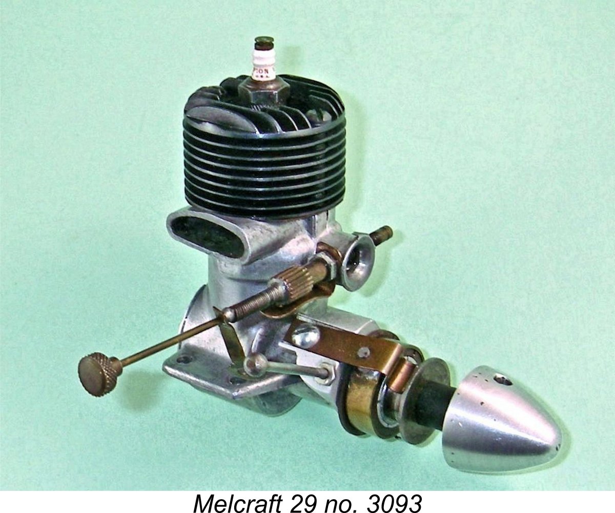
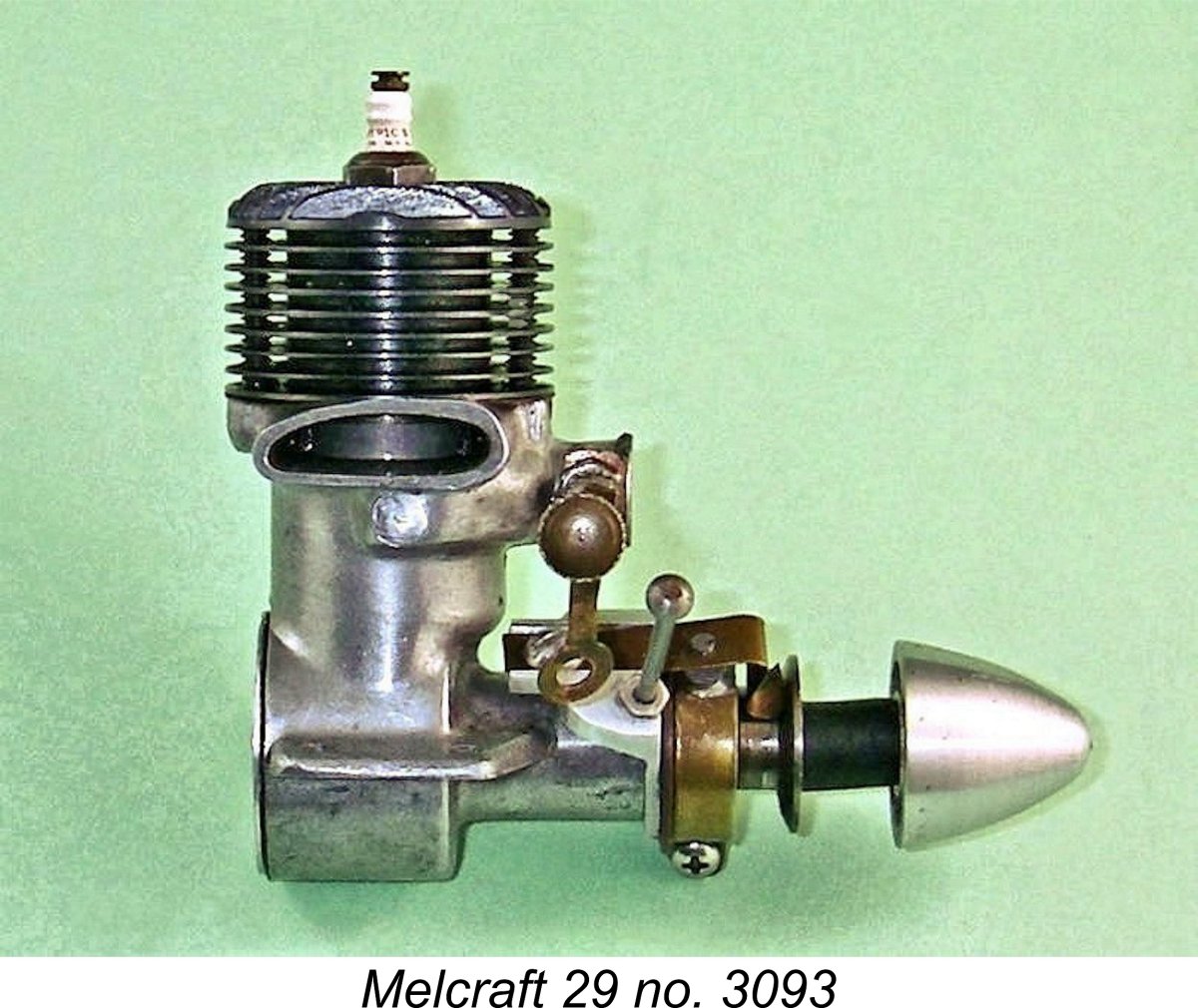
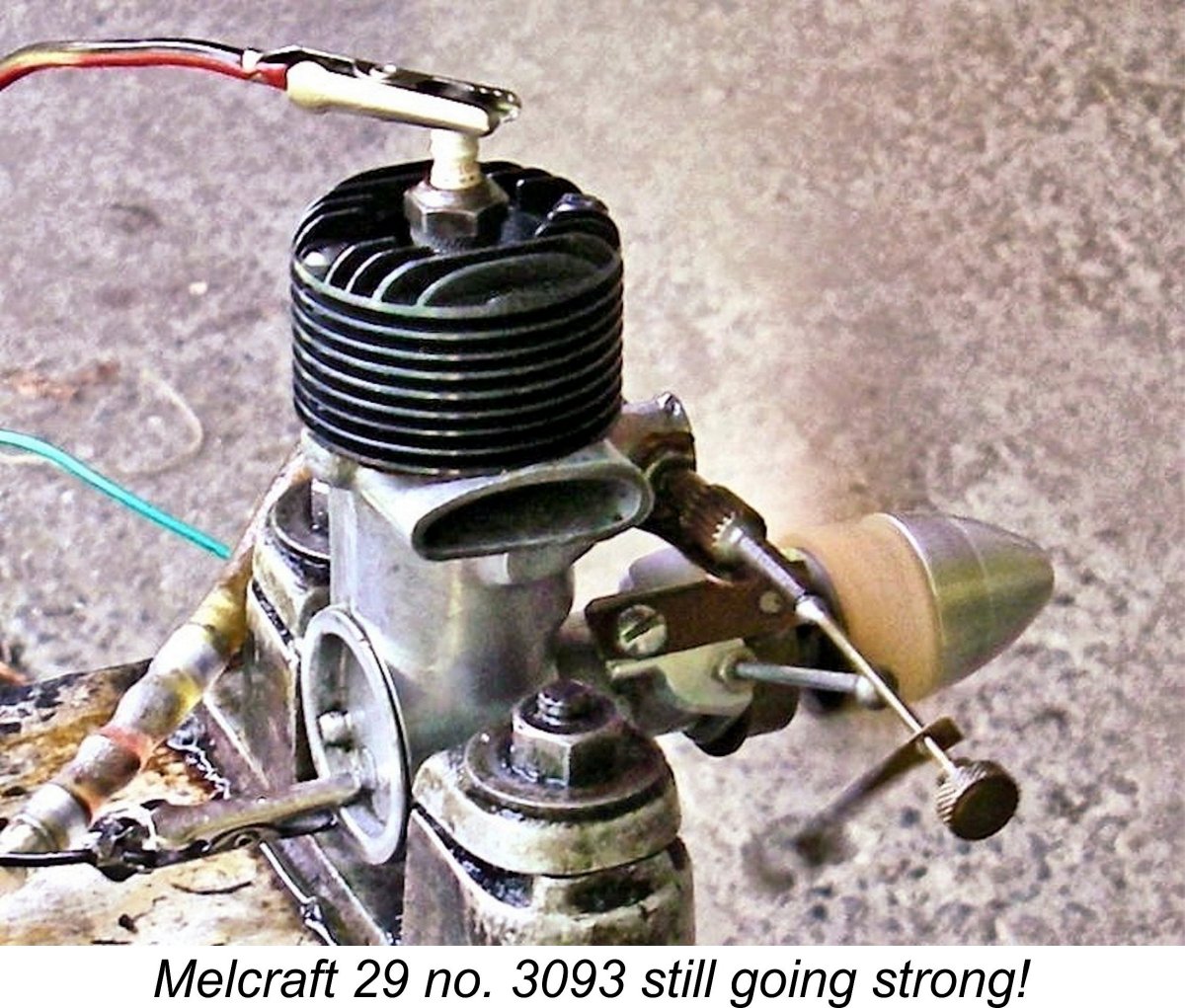
The most immediately obvious external difference between this variant and the previous model is the fact that the exhaust stack is now longer and is cut off at an angle to the engine’s fore-and-aft axis, being shorter at the rear. Initially a rigid needle control continued to be used, but many later examples feature a needle valve having a long flexible extension with a clip to facilitate adjustment from the exhaust side. A plain unplated fuel tank was supplied for use with these motors. This was not an integral feature of the engines but was intended to be mounted separately in the model. Many surviving examples have become separated from their tanks. For reasons which are not entirely clear, the checked weight of my example of this model (engine no. 3093) is considerably higher than the cited weight of the original Blue Streak product. My engine weighs 6.91 ounces (196 gm) with plug but without tank or ignition support system. I have no explanation for this discrepancy except to say that the manufacturer’s cited figure may have been a little “under-stated” for promotional reasons. Based on the results of Tim Dannels’ survey, serial numbers for this variant seem to start at around 2000, continuing the sequence started with the Blue Streak. The numbers appear to go up to 3200 or thereabouts. Melcraft 29 - 1946-1947
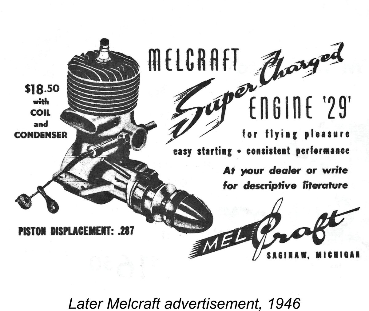
The major functional change was the addition of an additional “anti-float” leaf spring acting upon the moving point of the timer assembly. Photographs prove that these additional springs were retro-fitted to a number of earlier units by their owners, indicating that this was a worthwhile modification. In addition, the metal fuel tanks were now cadmium-plated. It's possible that the cam profile was also reconfigured to increase the dwell period, although I'm unable to confirm this since I don't have access to an example of this model. Perhaps some kind reader could enlighten us?!? Tim Dannels’ survey confirmed that the serial numbers applied to this version start at around 3200 and go on up from there. The highest serial number reported in Tim’s survey was 4172, confirming that at least that many were made in total. In addition, several engines were reported that do not bear serial numbers at all. This being the case, it’s impossible to present an authoritative figure for the total produced except to say that a considerable number clearly did in fact reach the market. We probably wouldn't be far wrong to suggest that total production may have reached 4500. Media coverage The Melcraft 29 didn’t made its appearance in time to be included in the article entitled “Construction Features of Model Engines” by Edward G. Ingram which was published in the June 1945 issue of “Model Airplane News” (MAN) while WW2 was still ongoing in the Pacific theatre. However, it was well established by mid 1946, appearing in Ingram’s article entitled “Recent Model Engines” which was published in the June 1946 issue of MAN. The data table which accompanied this article confirmed all of the previously-noted construction details. The text read as follows: “In the Class B Melcraft, the upper extension of the crankcase incorporates a patented feature consisting of a cast-in passage running around one side of the cylinder which permits the air intake to be located where it will receive the air blast from the propeller and forward motion of the plane. The increased air pressure tends to force a greater charge into the crankcase, which is termed supercharging. The gas passage runs under the integrally-cast exhaust stack, so the entering charge is pre-heated. The crankcase, which is die-cast from aluminum alloy, is of compact design having a diameter of 11/8 in. at mounting level and is machined at the points where the cylinder, main bearing and cover plate fit against it. Alloy steel is the material used for the cylinder, which is machined from a solid billet, the head being integral. The connecting rod is also of alloy steel and is provided with a bronze bushing at the lower end. No bushing is provided at the upper end of the rod because a bronze wrist pin is used. A Chrysler Oilite bearing 1¼ in. long supports the crankshaft. The cylinder has a bore of 0.7651 in. and a 0.625 in. stroke, which makes the piston displacement .287 cuin. For control line flying, a 10 inch diameter 6 inch pitch propeller is recommended, and for free flight an 11 in. diameter 4 in. pitch propeller”. The Melcraft was included in the data tables which accompanied in Ingram’s article entitled “Model Motor Symposium”” which appeared in the December 1946 issue of MAN. The technical data was unchanged, but the table now included some performance-related data. An output of 0.200 BHP at 10,000 rpm was claimed. These figures appear more than a little optimistic to me, undoubtedly requiring independent evaluation (see below). The prop recommendations of a 10x6 for control line and an 11x4 for free flight were carried over from the previous article, but the claim was now included that the engine would turn either of these props at 8,000 rpm. If the 10x6 were a modern APC item, such a speed would imply an output only a little shy of the claimed 0.200 BHP. However, once again this is a claim that warrants checking ………….the fundamental nature of the design would not lead one to expect such figures. The Melcraft was not mentioned in the text, which understandably focused on more recent offerings. The Melcraft was not mentioned in Ingram’s next major article entitled “Latest Model Motors” which appeared in the April 1947 issue of MAN. The engine was certainly still in production at this point in time, but as the title suggests, the article focused upon then-recently introduced products. The Melcraft had been in production for at least 18 months when this article appeared. Of possibly greater significance is the fact that the Melcraft was not included in Ingram’s article entitled “Model Motors for 1948” which appeared in the January 1948 issue of MAN. This purported to be a complete listing of all American motors expected to be on the market as of 1948. The absence of the Melcraft from this listing implies an understanding on Ingram's part that the engine would not remain on offer for 1948. Indeed, it appears all but certain that production of the Melcraft engines ended in late 1947 or just possibly early 1948. The glow-plug had well and truly arrived on the scene by that time, making it imperative that any manufacturer wishing to remain in the model engine marketplace would have to start developing glow-plug models immediately. There’s no evidence that Melcraft ever did so. The Melcraft 29 on Test
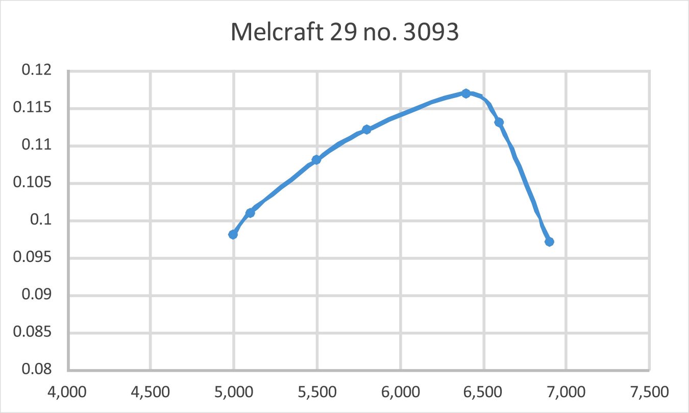
A continuity test of the timer showed that it functioned perfectly at turn-over speeds, so I expected that the engine would at least start OK. I elected to follow the manufacturer's recommendation by using my standard sparkie fuel consisting of three parts of Coleman camp fuel (white gas) to one part of SAE 60 oil. I chose a 10x6 Zinger wood prop for the initial runs since that was one of the recommended sizes. For some reason, it just seems more appropriate to test a sparkie using a wood prop …………. I hooked the engine up to one of my Larry Davidson transistor-triggered spark ignition support systems and was all set. I was expecting a fairly easy time with this engine, but initially it didn't happen. It turned out that the engine liked to be relatively wet for starting, in contrast to most sparkers. It seemed to prefer both a small intake prime and a small exhaust prime. It took me a little while to work this out, during which time I found starting to be somewhat hit and miss. On a port prime alone, the engine delivered a short firing burst and then stopped. On an intake prime or finger-choking alone, it didn't even fire. I had to administer both. These issues were perhaps caused Running qualities were excellent at all speeds tested. However, the engine's pronounced sensitivity to the needle posed a challenge - the absolute best setting was not as easy to establish as with some other sparkies that I've tried. Again, this was very much in line with earlier predictions with respect to the engine's suction. A very small movement of the needle produced a big effect on running, sometimes to the point of causing the engine to stop. Once a setting was established, though, the Melcraft ran very steadily indeed. Vibration levels were quite modest. My previously-stated reservations regarding the engine's performance potential soon proved to be well founded. The motor could only manage 6,400 rpm on the 10x6 as opposed to the claimed 8,000 rpm cited by Edward Ingram. It's true that the prop I was using was doubtless very different from the one on which that claim was based, but even so ......... I actually found that the engine really didn't want to run much faster even on a significantly lighter load. I tried a far "faster" 10x4, which only yielded an extra 500 rpm along with a steep decline in output. The measured data are summarized below.
As can be seen, it transpired that the engine was turning the 10x6 Top Flite Power Point wood prop right at its peaking speed of 6,400 rpm, at which figure it was developing some 0.117 BHP. Frankly, this is more or less the kind of performance level that I'd expect from this engine, and it's really not too shabby for a 4.7 cc sideport sparker dating back to 1945. There's certainly no support at all for the claimed 0.200 BHP @ 10,000 rpm cited by Edward Ingram. The rapid drop-off past the peak is typical of engines using side-port induction.
The ignition system appeared to be still working well at the highest speed tested - no sign of any issues with under-saturation of the coil despite the short dwell period and the rather weak point closure spring. How much faster one could push that timer is of course another question, but as matters transpire it's a moot point - factors other than the timer clearly limit the engine's maximum speed potential. Even so, we seem to be looking at a well-made and user-friendly engine which would doubtless have served its owners very well provided they weren't looking for the ultimate in performance. It should have had a long and useful life if well cared for and appropriately operated. Conclusion
This very unusual engine was the subject of a test by Peter Chinn which was published in the November 1963 issue of "Model Aircraft". The little Jena performed at a surprising level for a side-port design, developing 0.088 BHP @ 14,000 rpm, a perfectly respectable performance for a 1 cc sports diesel of its time. The engine's long shaft and squat stature made it particularly suitable for scale models. The Melcraft 29 in its various configurations was a refreshingly "different" design which represented a very sincere effort by the two Mels to produce an engine having something So let's give due credit to Mel Schmidt and Mel Bluemlein! They were both enthusiastic modellers and talented machinists who followed their dreams to establish a business whose products served their fellow modellers well. I for one would doubtless have very much enjoyed making their personal acquaintance. The Melcraft engines were made in sufficient numbers that quite a few good examples survive today, being rather under-appreciated and hence often changing hands at quite reasonable prices. Any model engine enthusiast who comes into possession of one of these unusual engines will unquestionably enjoy that experience just as much as I enjoyed researching this article! __________________________ Article © Adrian C. Duncan, Coquitlam, British Columbia, Canada First published July 2021
|
||
 In this article, I’ll present a review of another of the early post-WW2 products of the American model engine manufacturing industry - the Melcraft 29 spark ignition model. This very well-made and somewhat unusual plain bearing side-port unit was produced in fairly substantial numbers by the Melcraft Machine & Motors Co. of Saginaw, Michigan, USA between 1945 and 1947.
 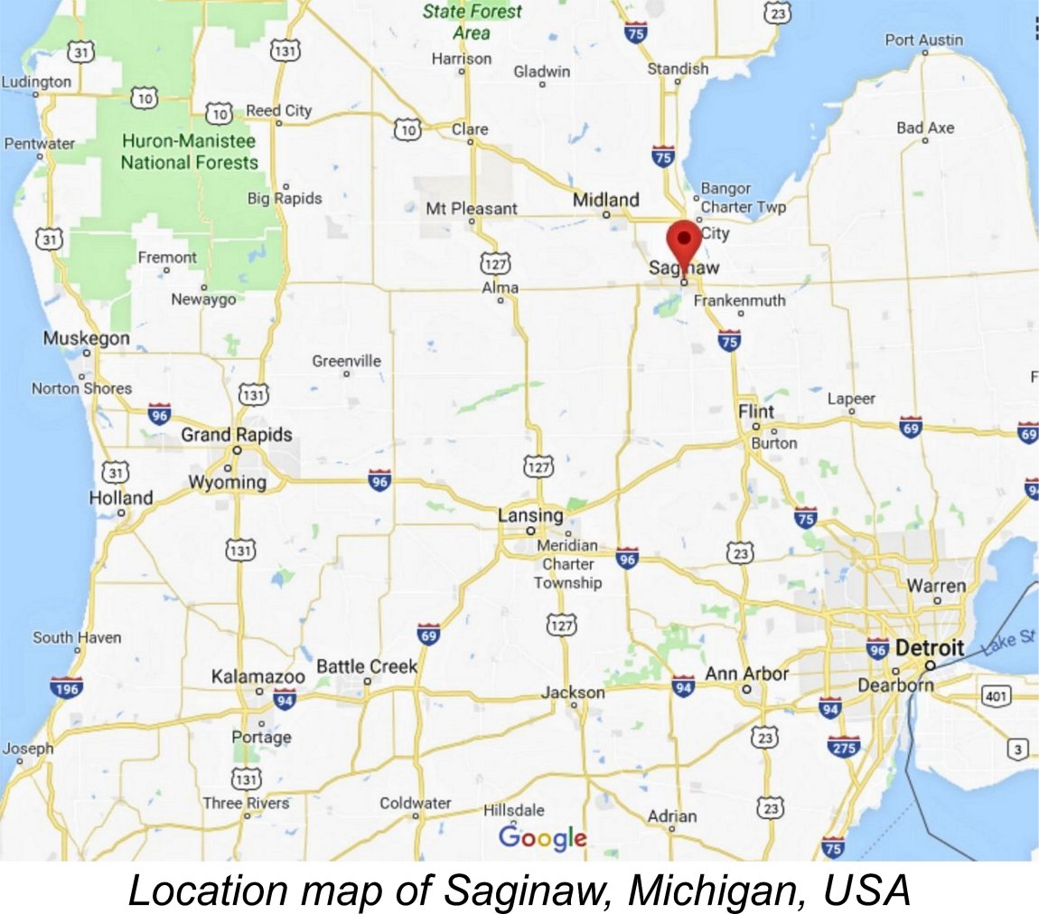 As its name suggests, the Melcraft venture stemmed from a partnership between two Mels - Mel Schmidt and Mel Bluemlein. Both were residents of Saginaw, Michigan, USA, a modest-sized town located in the Mid-Michigan region of the State near Saginaw Bay on Lake Huron. Along with the neighbouring communities of Bay City and Midland, it is considered to form part of Michigan’s Tri-City area.
 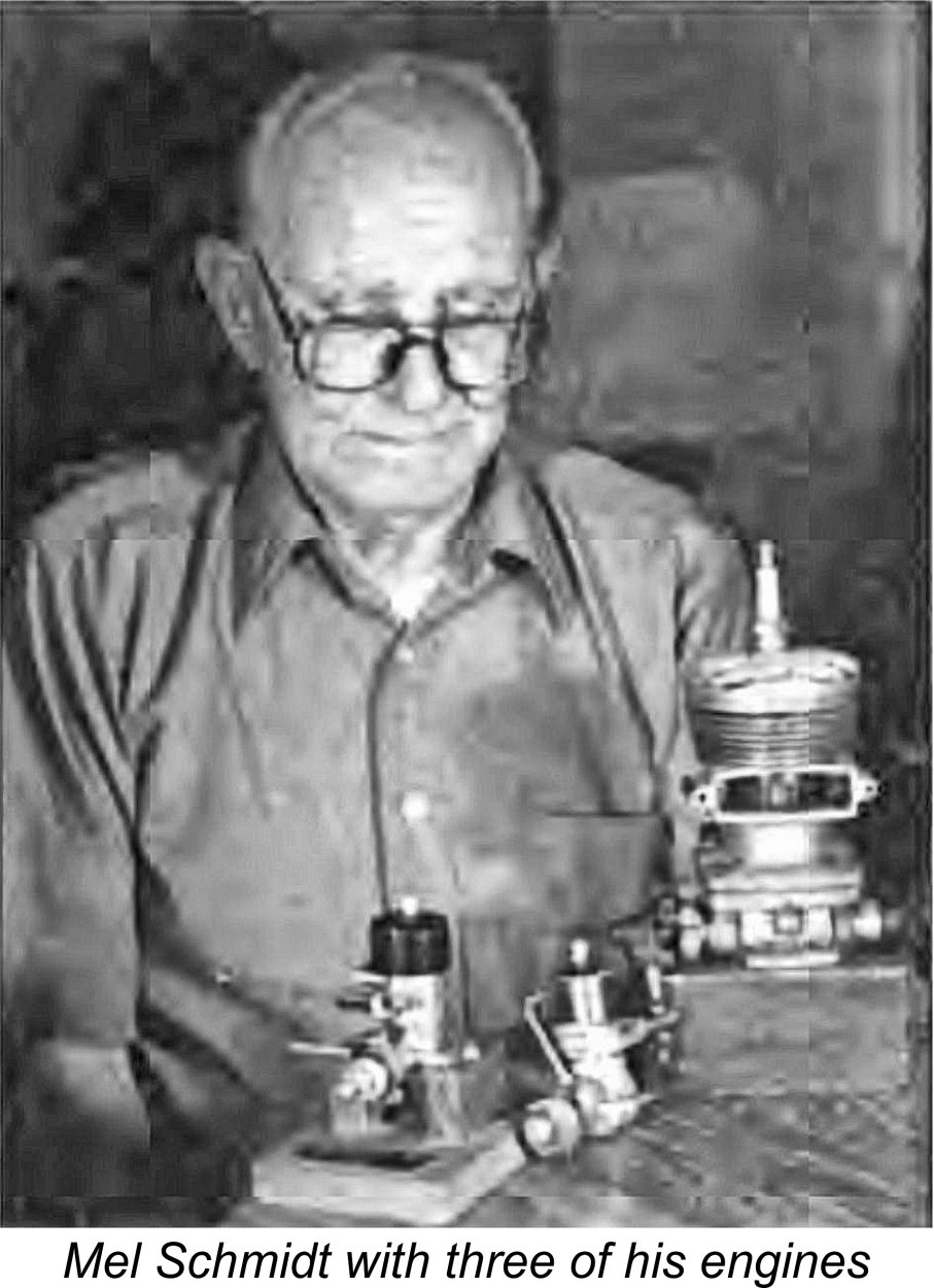 One of these units was a 3 horsepower behemoth looking not unlike an oversized Hornet 60. Mel used this to power his bicycle for travelling to and from work! That engine is seen in the accompanying photo of Mel in later years with a few of the other engines that he made. I’m sure that you could have heard him coming ……………..!!
 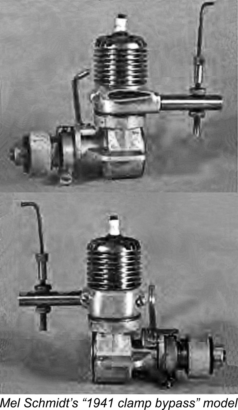 By early 1941 Mel’s skills had advanced to the point where he was able to put one of his designs into limited production. This was a simple plain bearing side-port unit of basically conventional layout. It featured a bypass created by attaching a separate piece of metal looking like half a clamp to the exterior of the transfer side of the engine to connect ports formed in the cylinder wall. Consequently, it has often been referred to as the “clamp bypass” model.
 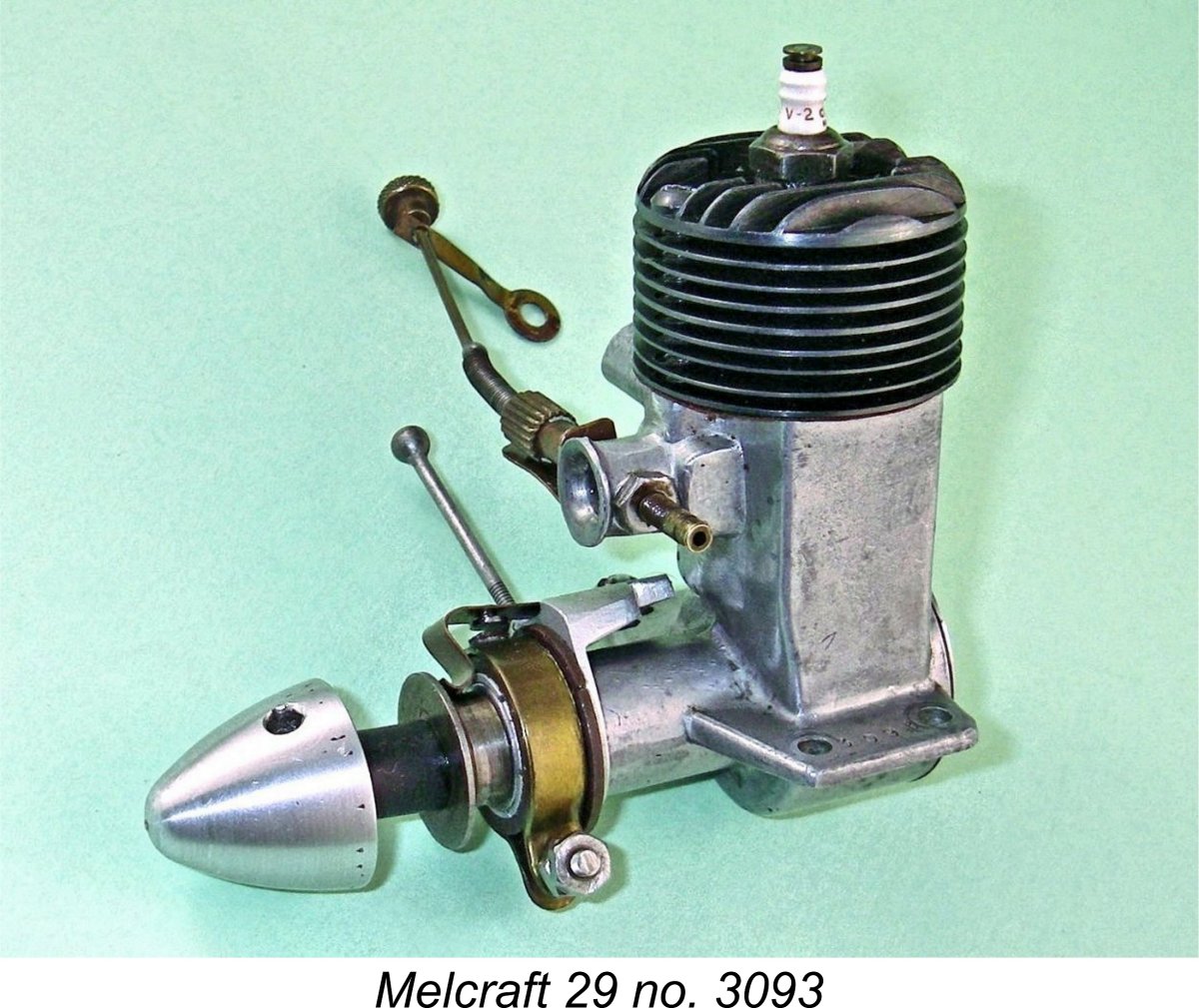 As the war drew towards its close, the partners began to look ahead. The commercial production of model engines in the USA actually resumed in around September 1944, following a decision by the US War Production Board to release sufficient material for non-military purposes to allow this to happen. This prompted a decision by the two Mels to re-enter this field in a big way after the war.
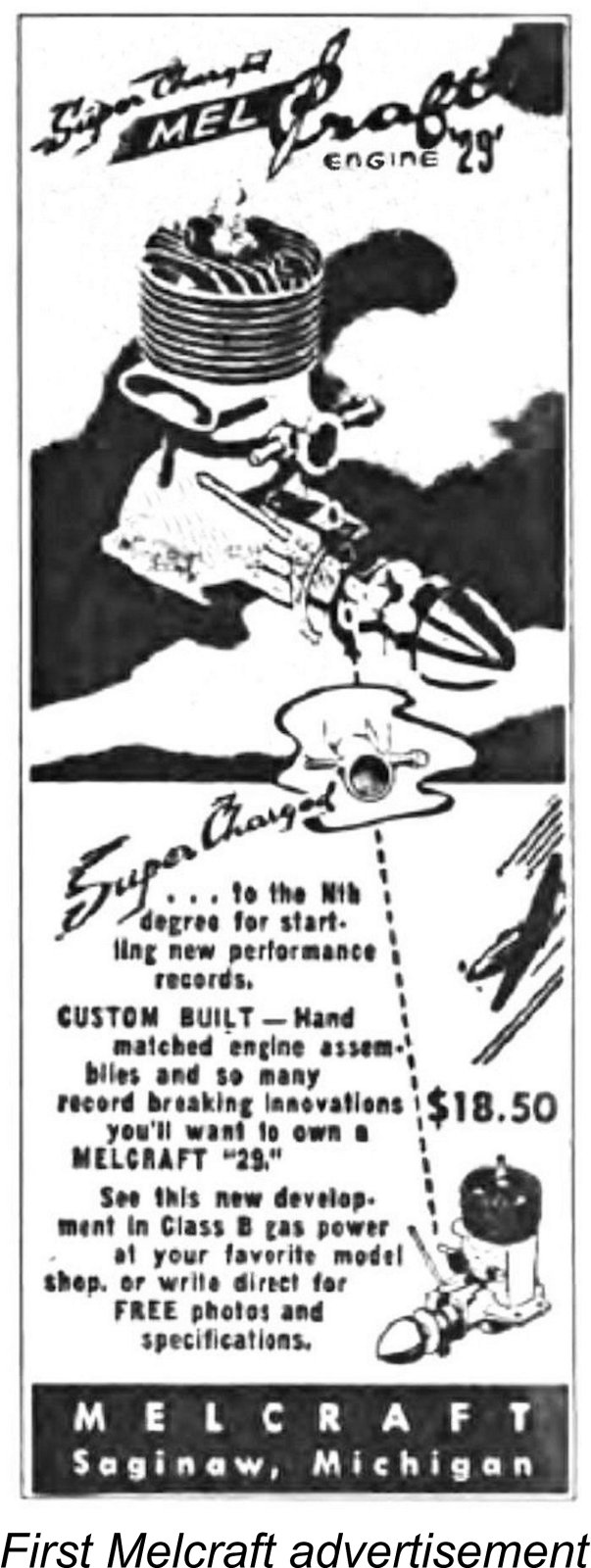
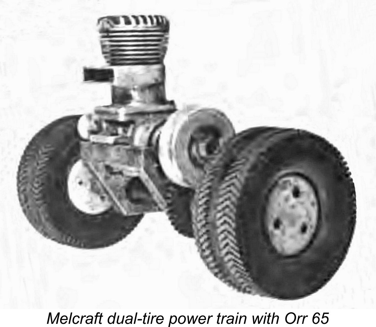 By 1946 model car racing was booming in America. The two Mels decided that they wanted a piece of this action also, developing a design for a .60 - .65 cuin. tether car, a category which was particularly popular. This car featured a transversely-mounted horizontally-oriented motor which drove the wheels through spur gearing. A cast aluminium alloy pan was used, with a carved balsa-wood top which could be custom-finished by the owner.
 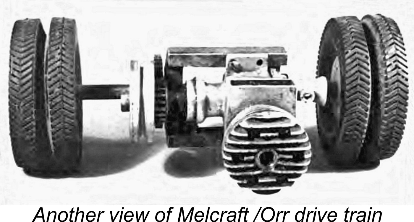 In early 1947 the new Melcraft car was taken to a major model show, but no orders were received. Once again, the two Mels looked for a “sales handle” to excite prospective customers, coming up with a rather radical driving axle featuring dual tyres on each side. This was touted as a means of improving traction. However, even this didn’t raise enough sales interest to justify continued production - in fact, all that it seemed to produce among serious car racing buffs was a certain sense of amusement, probably sparked by the resemblance to the rear wheels of a truck! Only around 200-300 examples of the Melcraft car ended up being produced. Very few survive.
 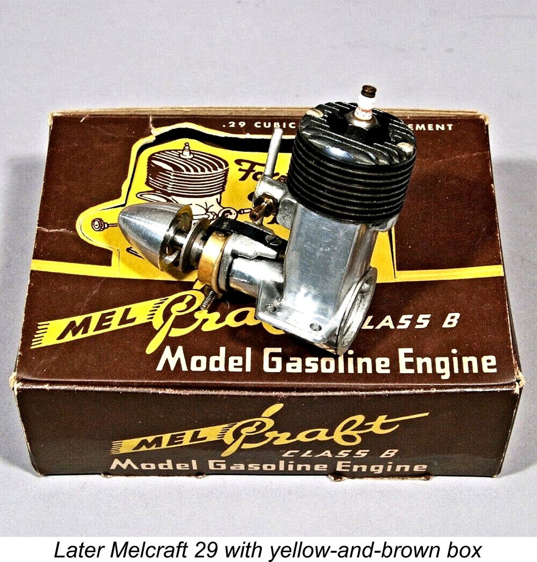 Sales of the engines were not confined to the continental United States. In fact, the largest single order ever received by the company came from South Africa, when a Johannesburg model shop placed an order for no fewer than 2,000 engines. Presumably model engines were in very short supply in South Africa at the time! The Johannesburg company appears to have been attempting to corner the market. It's unclear whether or not that order was actually completed and shipped.
 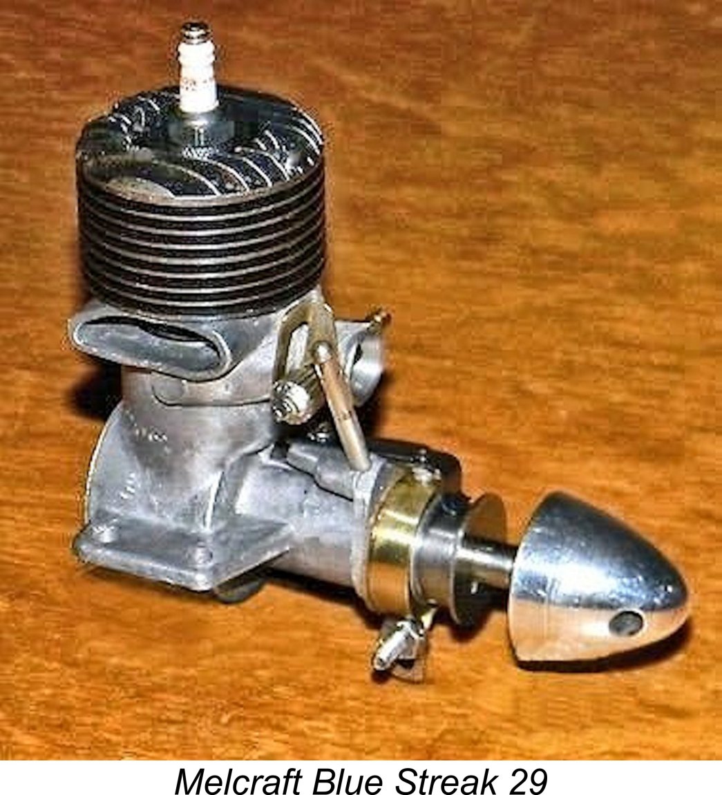 We saw earlier that the original Melcraft 29 was actually marketed under that name at the outset - the short-lived switch to the Blue Streak name came a little later. However, that original unit was identical to the model generally referred to as the Blue Streak 29, so I'll stick with that identification.
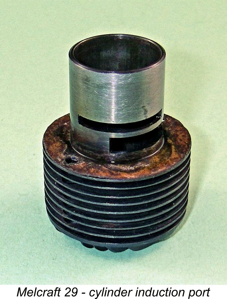
 This variant was basically very similar to the Bluestreak, but most examples apart from the very early ones do not display knockout marks on the bypass, which is still flat. As noted earlier, it had been found to be unnecessary to make knock-out provision for these castings, since they were easily released from the dies without intervention.
 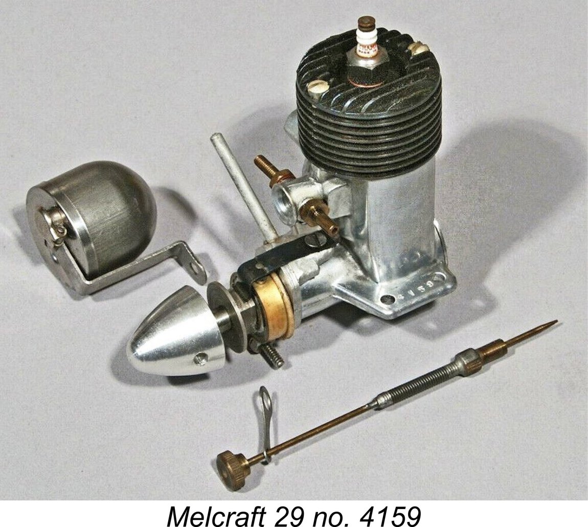 Once again, this variant was very little changed from its predecessors - in fundamental design terms, it was the same engine. The most obvious external difference is that the crankcase die was slightly modified to impart a curve to the bypass surface. This may have had the effect of slightly increasing the bypass area. In addition, the castings on most examples were given a highly polished finish. The long flexible needle valve control introduced on the previous model was retained, although a few NIB examples have shown up with rigid needles.
 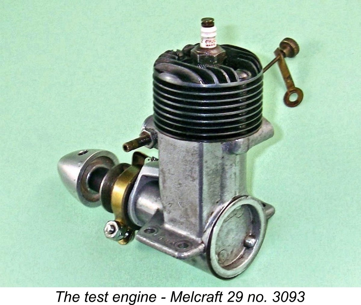 Having learned this much about the Melcraft 29, I was keen to get my second model no. 3093 into the test stand. Although clearly used, this example seems to have had relatively little running time, hence remaining in near-pristine condition, complete and original. As such, it should deliver a fully representative performance.
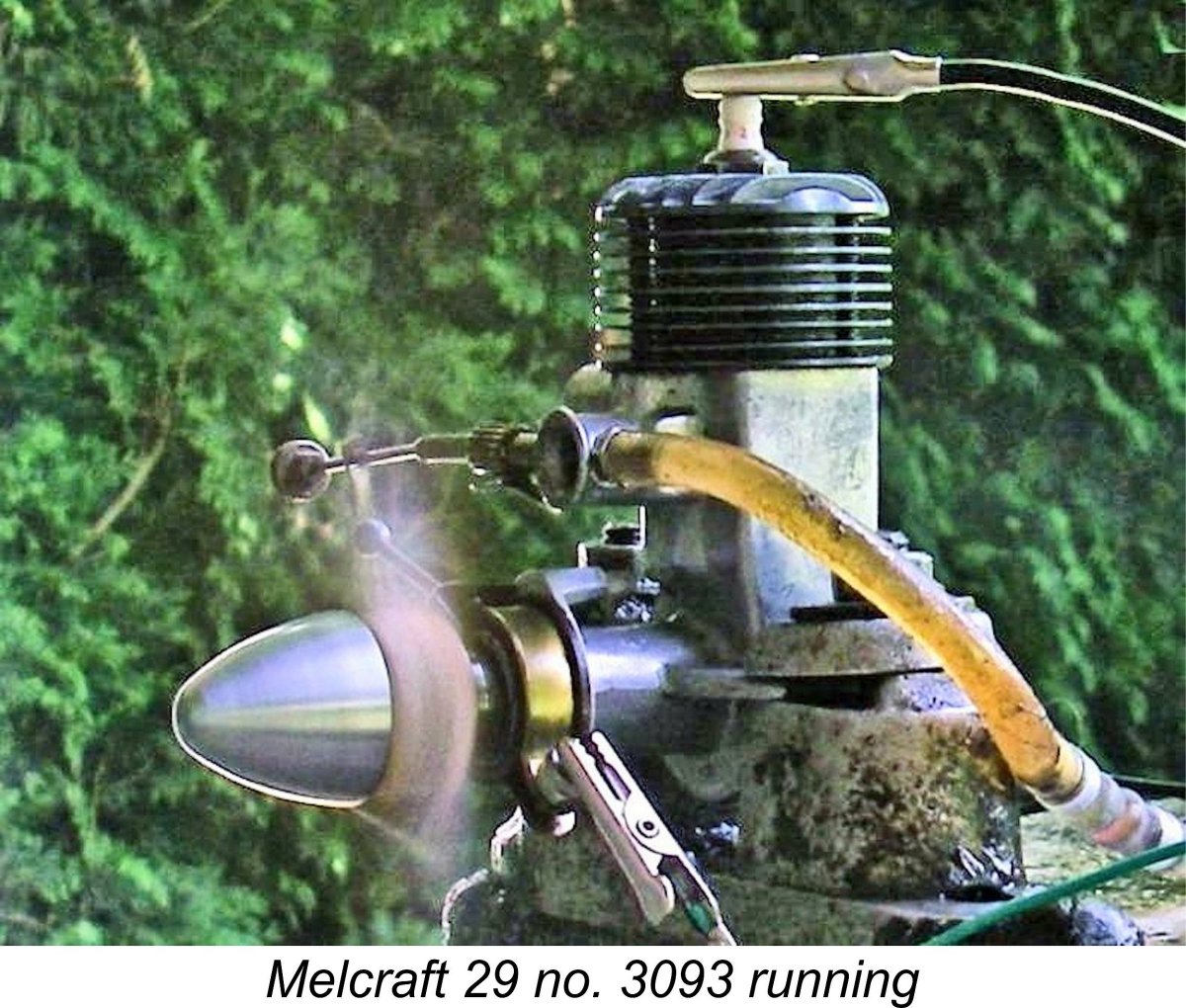
 Just for fun, I tried holding a small metal "paddle" just in front of the intake while the engine was running at full speed on the 10x6. This of course killed any ram air effect which might have been influencing the induction. The engine continued to run exactly as before - the interruption of the ram effect did not reduce the performance in any measurable way. Oh well ....... it was a good sales gimmick!! However, I'd bet that the engine would needle better with a more conventional induction placement utilizing a longer induction tube.
 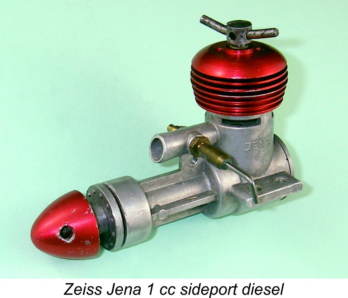 The use of a forward-facing intake on a side-port engine was not unique to Melcraft, although their 29 model appears to represent the first application of this arrangement to a production model engine. Years later, the
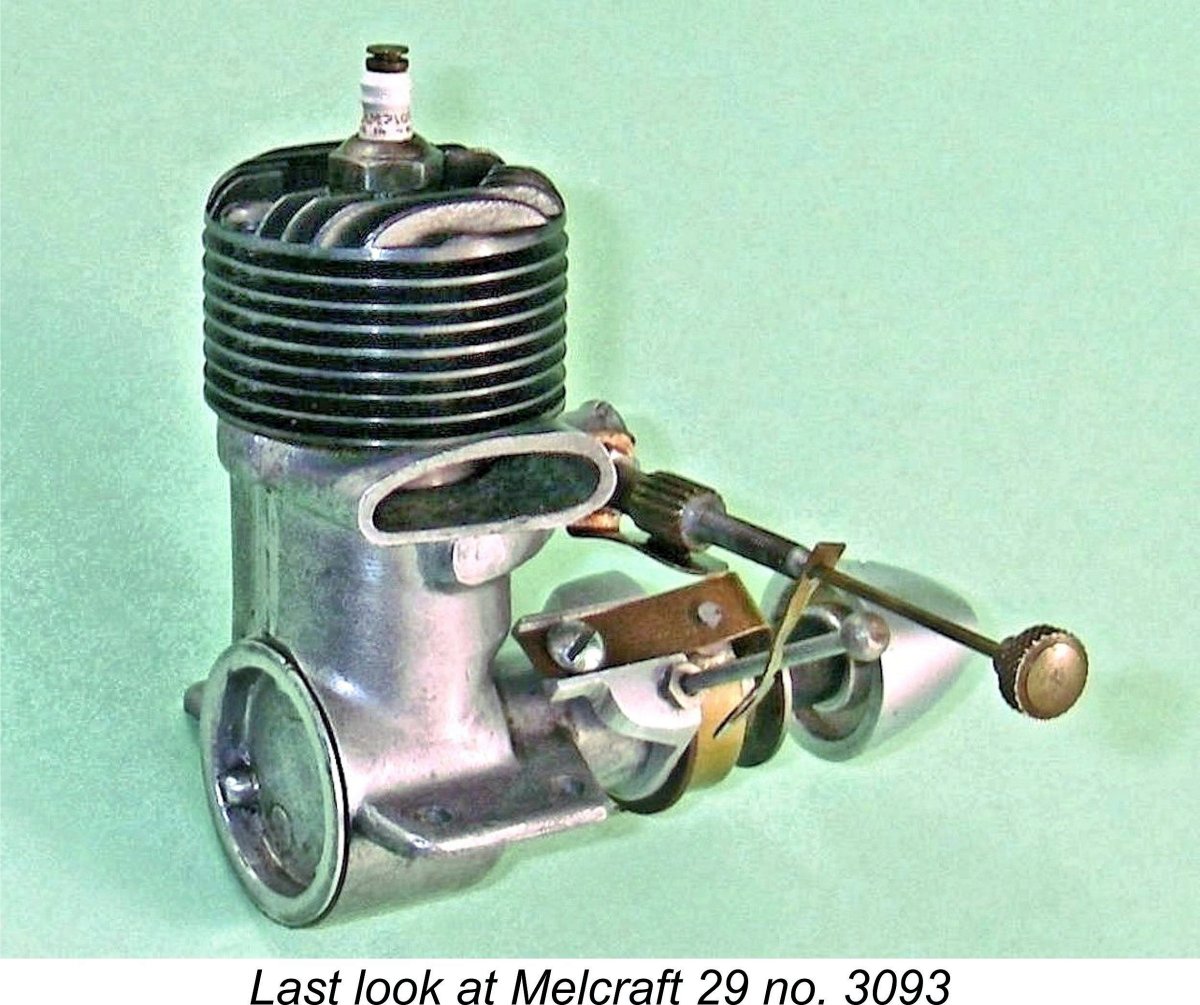
| |