
|
|
The E.D. 2.49 cc Mk. III by Adrian Duncan with Kevin Richards
The Mk. III has always been one of my personal favorites from the early post-WW2 era. Apart from the fact that it’s a nice engine to run, it combines a unique mix of pioneering and second-generation features in a delightfully old-world package. Its primitive-looking “stovepipe” cylinder with soldered-on bypass passage and long-stroke geometry combine perfectly with its extended prop driver, forward-looking front rotary valve (FRV) induction and roller bearing crankshaft (on later examples) to create an irresistible mix of old and not quite so old features in a decidedly one-off package. The reason for this re-draft of the original article is two-fold. First, upon re-reading the former article some years after writing it I found it to be poorly organized, with a number of ill-founded or ill-expressed conclusions, for all of which I take full responsibility. At the time when I wrote it (2007), I was still relatively new to the challenge of presenting the history of these old engines in an authoritative and informative manner, and it showed! And secondly, the original article did not incorporate any latter-day testing results. The present rewrite will address both issues. This highly individualistic engine has the distinction of being the first of only three models produced by the original E.D. company to feature crankshaft front rotary valve (FRV) induction. The others were the E.D. Baby 0.46 cc diesel of 1952 and the 1960 E.D. Pep of 0.81 cc displacement. Throughout the marque’s long history, the majority of engines released under the E.D. banner were rear induction rotary valve models, the major exceptions being the original sideport 2 cc diesels with which the company got its start. Much more of those models elsewhere. At the time when the Mk. III was released in early 1948, there was no particular significance to the 2.5 cc displacement category as far as model aircraft were concerned. The FAI’s adoption of that displacement for International power competitions (excluding R/C and control line stunt) lay some years in the future. The Mk. III’s larger displacement seemingly represented an attempt to produce an engine having a bit more power than the company’s 2 cc side-port offerings which preceded it, at the same time taking full advantage of the 2.5 cc displacement limit applied to both the British Class “C” tether car category and the then newly-introduced Society of Model Aeronautical Engineers (S.M.A.E.) Class II control line speed category. As with the original article on MEN, I have continued to rely heavily upon information provided by my friend and colleague Kevin Richards. Since Kevin is undoubtedly the world’s leading authority on the E.D. range, writing a credible article on any of the engines produced under that brand-name without consulting him would be impossible. I’m extremely grateful to Kevin for his generous sharing of so much hard-won information on E.D. engines. Kevin has been working for some years now on a book about the E.D. range. I have no doubt that this book will represent the last word on the E.D. marque and will reveal far more details than space or knowledge allow me to present here. All that I will attempt is a summary of what I consider to be the main points of interest. The devil’s in the details, and I‘ll leave most of those to Kevin. I’ll be among his first customers! Now to start the ball rolling, let’s go back to the beginning and summarize the story of the E.D. company’s model engine development program leading up to the introduction of the Mk. III. Readers who are already familiar with that phase of the story are invited to skip to the following section of this article. Background
The E.D. premises were re-developed from a converted commercial-scale Sanitary Laundry which had occupied the site prior to WW2. According to later reports, the floor area of these premises was around 4,500 square feet. My sincere thanks to Mike Noakes for providing this information along with the attached 1952 air photo of the E.D factory. The location has been comprehensively redeveloped today for residential purposes. The original E.D. company appeared on the scene in 1946 shortly after the end of World War 2. It was formed by a group of individuals who for the most part had worked during the war years for Nash & Thompson of Kingston upon Thames, along with a few redundant employees of the Hawker Siddeley group who were headquartered in the same community. Pending the publication of Kevin Richards' book, the full story of the company’s establishment and ongoing history may be found in a separate article on this website. Although originally established with an eye towards the specialty electronics market (as the name suggests), E.D. began to develop their range of commercial compression ignition (“diesel”) engines in mid 1946, quite soon after the formation of the company. Their initial effort was a somewhat primitive sideport model known simply as the E.D. 2 cc diesel. Reports in the contemporary modelling media indicate that examples of this engine began to appear on flying fields in southern England in late 1946 with little or no commercial fanfare. Kevin Richards believed that this original model was never offered for public sale and that the engines seen in action in late 1946 were development prototypes in the hands of E.D. employees. This seems entirely plausible to me in the current absence of any convincing evidence to the contrary.
In his April 1955 announcement of the then-forthcoming J.B. model engine range, founding E.D. Managing Director Jack Ballard claimed that J.B. designer Charlie Cray had been “primarily responsible for all the engines manufactured by me (Ballard) during the past ten years”. While this was clearly a gross misrepresentation of the facts since it completely ignored the very significant contributions of Basil Miles, Dennis Allen and Ted Martin, it may nonetheless harbour a kernel of truth. It appears that Charlie Cray may well have had at least some responsibility for the early E.D. models, including the Mk. III. His signature appears on at least one of the surviving design drawings for these early models. It can't be denied that the design of these engines represented a significant step backwards from the far more sophisticated designs which had been produced by Basil Miles prior to and immediately following WW2. Hence it has always been difficult to believe that Miles had a major influence on the development of the early E.D. model engine designs. It's highly unlikely that a designer of his calibre would have missed some of the very obvious and easily implemented design improvements which would have done much to improve these engines. Nonetheless, the fact that Miles and the original E.D. designer Charlie Cray were fellow members of the Malden model hydroplane racing club would doubtless have facilitated Miles' input to engine developments at E.D., ultimately leading to his central role in the design of later models. The original E.D. 2 cc design of late 1946 was quickly transmuted with relatively minor changes into the initial version of the famous E.D. Mk. II “Penny-slot” model (as it soon came to be colloquially known). Surviving serial numbers confirm that the E.D. Mk. II made its market debut by that name in February 1947 and was energetically promoted and further developed from that point onwards.
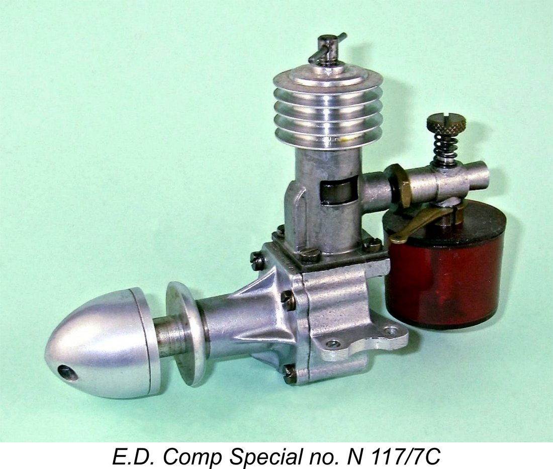
However, all was not perfect behind the scenes. It's readily apparent from an objective review of its early development history that the Mk. II was released rather prematurely in a relatively under-developed form. This was almost certainly done to generate some quick cash flow from E.D.’s engine program, thereby justifying the program’s existence. In taking this approach, E.D. was anticipating the pattern employed by many present-day computer software companies - get a relatively under-developed product into the field as soon as possible and use the cash flow from sales to fund the ongoing development program. Your customers will perform your field testing for you (provided the product is not too awful!), and you can respond to any identified issues by releasing updates as required, thus appearing to be responsive to customer feedback. The production volumes extrapolated from the serial numbers for examples of the Mk. II produced during this period suggest that this strategy almost certainly paid off in a financial sense - sales were clearly quite brisk despite the initial shortcomings of the design. However, there was a downside - the engine’s under- By the time in question, the annual Christmas issue of “Aeromodeller” had become something of a tradition as far as the British and Commonwealth modelling scenes were concerned. It was a double size "bumper" issue which was eagerly awaited by the modelling public. E.D. took full advantage of this by announcing the “Competition Special” refinement of the Mk. II (always colloquially known as the Comp Special) in the December 1947 Christmas issue (which actually appeared on the news-stands in the latter half of November). The Comp Special proved to be an immensely popular engine among sports fliers and model boat enthusiasts (in its watercooled form), surviving almost to the end of production by the “original” E.D. company in the early 1960’s. It was apparently the success of this motor that convinced the E.D. Directors that their hitherto “subsidiary” model engine manufacturing activities should thenceforth be viewed as a mainstream business line. It’s certainly true that the rapid expansion of the range commenced at this point. The first evidence that an expansion of the range was underway was the unheralded March 1948 appearance of our main subject - the E.D. Mk. III of 2.49 cc displacement. We'll get to that model in due course. However, before getting into our detailed discussion of the Mk. III, it’s worth spending a little time explaining the E.D. serial numbering system. This is because of the light that it sheds upon issues such as model changes and production figures. These numbers will be quoted frequently in what follows, so it will be helpful to be able to interpret them correctly. The E.D. Serial Numbering System During the first few years of model engine production just described, the E.D. company implemented a system of serial numbering which has stood latter-day model engine historians such as myself in very good stead. The system adopted was unique to my personal knowledge in that each number was completely descriptive of the individual engine to which it was applied, including the model, the year of manufacture, the month of manufacture and even the position of the engine in that month’s production batch. Can’t get any more descriptive than that! Since this system so completely defines the engines to which it was applied, it’s well worth taking a little time at this point to provide a clear understanding of the manner in which it was used on the E.D. Mk. III. Basically, the number applied to each engine contained the following elements:
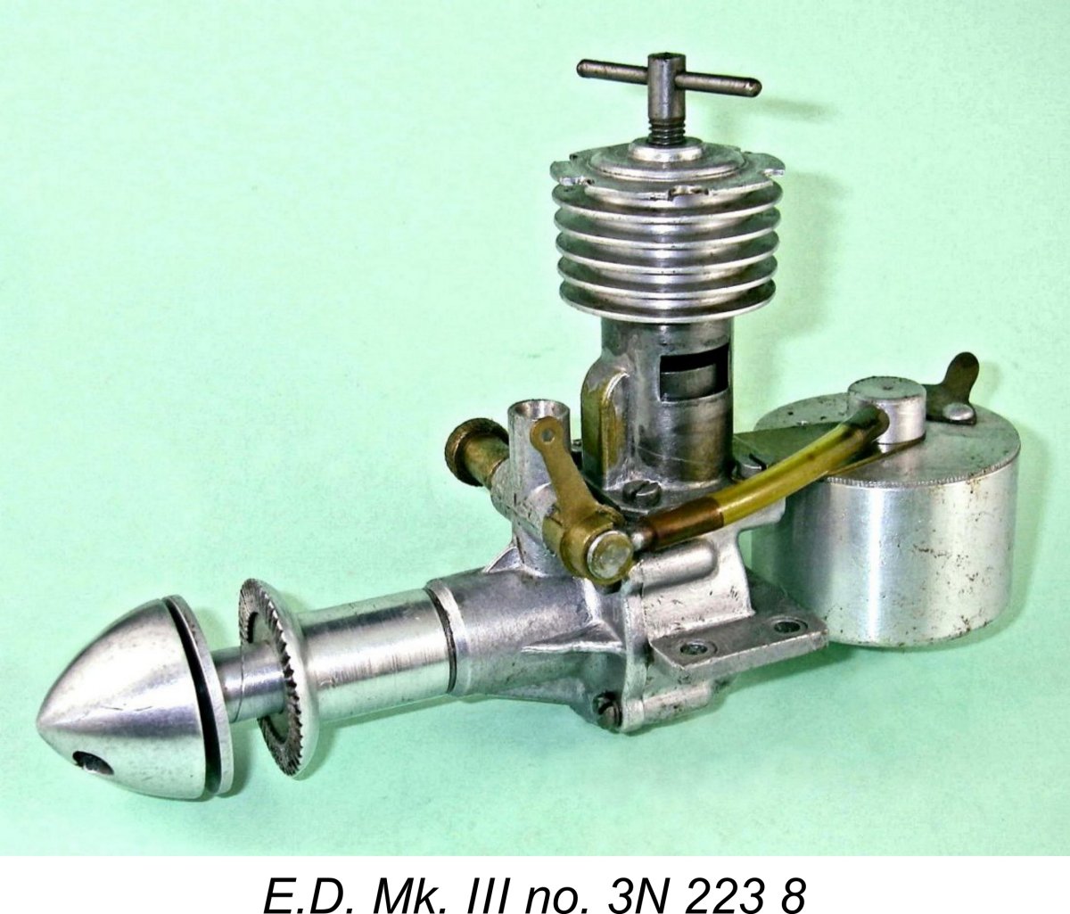
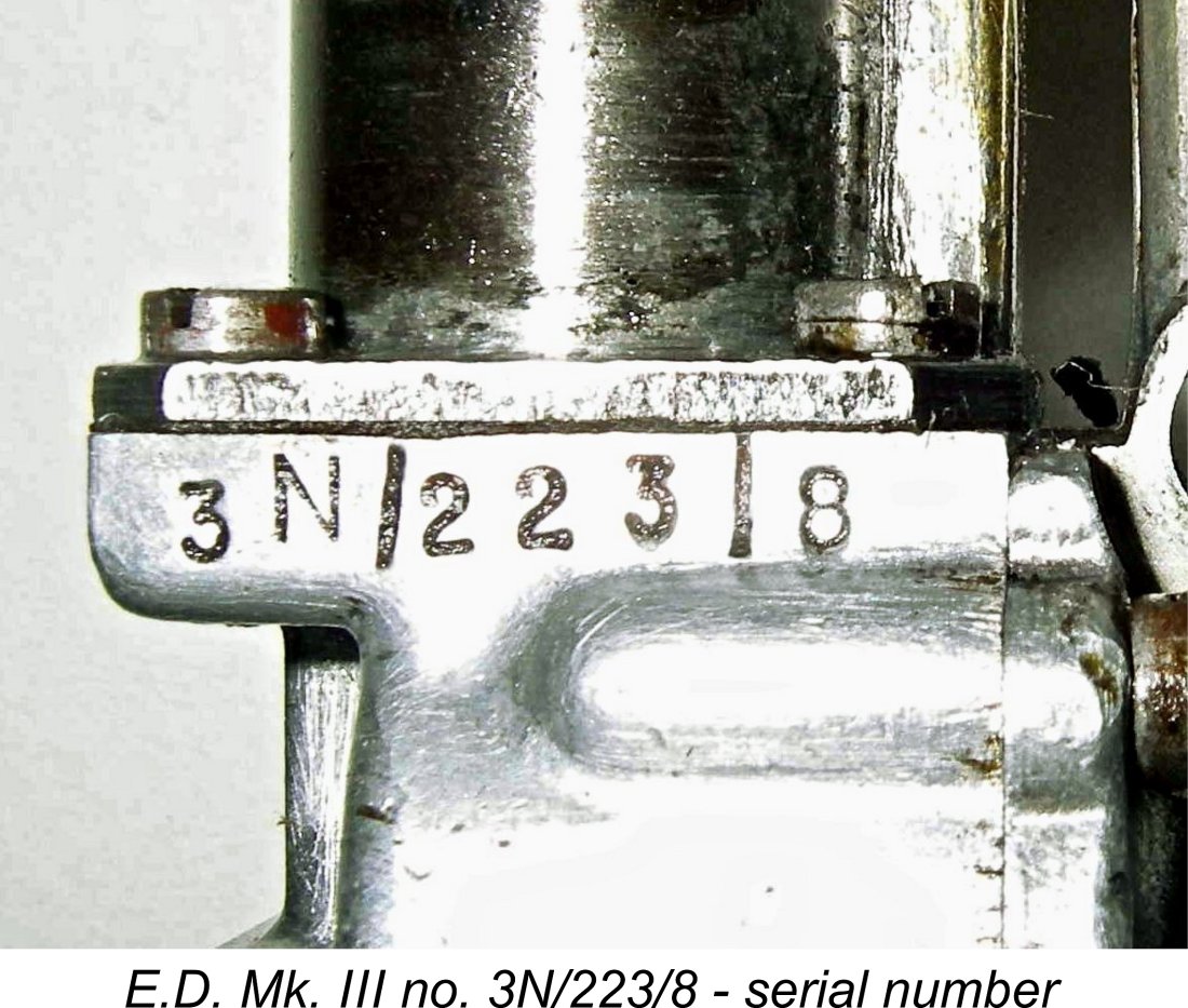
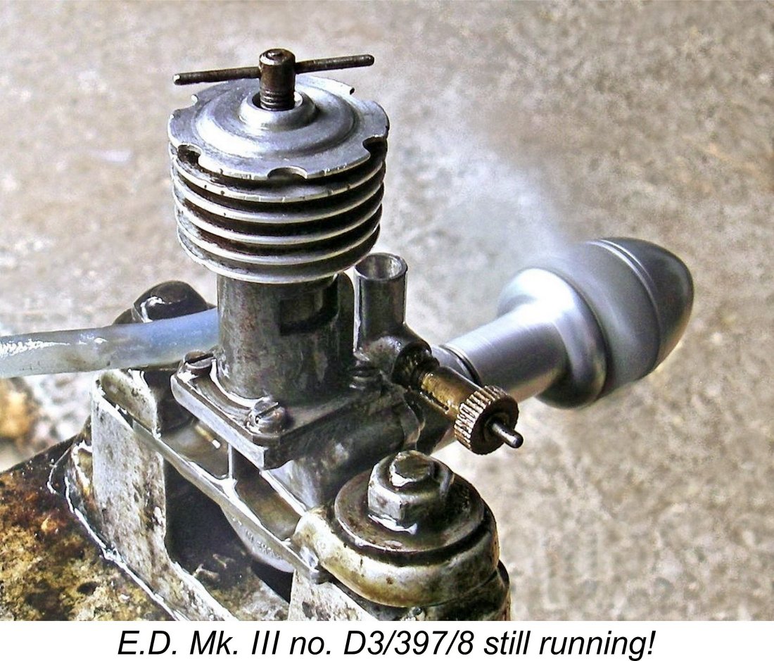
The E.D. Mk. III was assigned the model number 3, which appeared either immediately before or immediately after the batch letter. So for example, E.D. engine number E3/166/8 is a Mk. III made in May 1948 as the 166th such engine made that month. Engine number J3/48/8 is an E.D. Mk. III made in September 1948 as the 48th example made that month. The illustrated unit bearing the serial number 3N/223/8 reverses the order of the first two symbols but this still indicates an E.D. Mk. III made in December 1948 as the 223rd example made that month. And so it goes ………. This system allows owners to identify and date their individual engines to a level of precision not possible with other makes from the same era. It also allows the easy identification of engines which have been restored to operating condition through the grafting-on of parts from a different variant - very common with the early sideport models, for example, and by no means unknown with the Mk. III. It would have been really great for us historians and restorers if others had followed suit! However, our needs didn't have much of a priority at the time............ The E.D. Mk. III - General Description
The same "stovepipe" cylinder design was retained, having twin large-sized rectangular exhaust ports providing a small period of sub-piston induction; a soldered-on rectangular section brass bypass passage; a deflector "step" milled into the piston crown on the transfer side; and a screw-on cooling jacket. The boss for the sideport induction was naturally omitted on most examples, the exceptions being a handful of factory-built sideport variants, of which more below in their place. The crankcases for the Mk. III were pressure die-cast from the outset. Full advantage was taken of the fact that the crankcase casting for the Mk. II and Comp Special could also be used for the Mk. III given that all models shared the same stroke. However, the extra bore required a change in the pitch circle diameter of the cylinder mounting screws. Therefore, fully machined Mk. II and Comp Special cases are not interchangeable with those for the Mk. III. The turned hardened steel conrod of the 2 cc models was retained, albeit with a larger rod diameter and a larger gudgeon pin diameter to accommodate the increased loading. However, the shaft was completely different, featuring a full-disc crankweb with no counterbalance along with a far greater journal diameter to accommodate the internal passage for the crankshaft rotary valve system which was utilized in place of the earlier sideport arrangement. The design of the crankpin possibly represents the Mk. III's Achilles' Heel in terms of longevity. It is very short, thus offering a relatively small bearing area to the conrod big end, with consequently elevated contact pressures. Even worse, the short big end bearing prevents the rod from self-stabilizing vertically during operation. Consequently the big end tends to move rearward on the crankpin, creating a tapered wear pattern on the pin. The taper further encourages the big end to move rearward, tilting the rod out of vertical alignment and eventually causing it to contact the backplate. No engine will give its best with a tilted rod rubbing on the backplate. That said, it appears based on experience that it takes a fair amount of running to fully develop this problem. The company's recommendation that only castor oil be used in these engines seems well warranted.
The crankshaft rotary valve used in this motor is well worthy of comment. The induction port in the large-diameter crankshaft was tangentially milled to form an arc around a portion of the circumference of the journal. This resulted in a round-ended port which was quite narrow in an axial direction but quite long in a circumferential direction. The round ends of the slot were doubtless most effective in limiting the development of stress concentrations at this always-vulnerable location. In conjunction with the relatively large crankshaft journal diameter (7/16 in. - 11.11 mm), the full opening and closing of this valve would be very rapid. Objectively speaking, I view this as a very good design.
The needle valve on the very earliest examples differed from that used on later units. The thimble was tensioned by an external coil spring as opposed to the internal spring used later. Moreover, the fuel spigot tube emerged from the end of the spraybar in a coaxial direction, being bent rearwards after its emergence. It was this version of the engine that was featured in both the Henry J. Nicholls advertisement of April 1948 and the E.D. placement in May 1948. An example is illustrated below in its place. Most examples used a brass thimble which was fitted with an internal tensioning spring, like that subsequently used on the 1 cc E.D. Mk. I Bee. In his early 1949 test of the Mk. III (of which more below), Lawrence Sparey reported that this spring alone was ineffective in terms of preventing vibration-induced needle valve creep when the engine was running. Later examples used a split in the thimble for tensioning, although the internal spring was retained.
The fuel supply side was fitted with a friction-fit cut-out arm that admitted air to the fuel line when rotated appropriately, interrupting the engine’s fuel suction and eventually shutting it down. Lawrence Sparey almost always reported such cut-outs as being less than highly effective at high speeds. Some aren’t, but most are ...............
The engine was supplied with a very large metal tank that hung under a sheet brass mounting bracket secured to the engine by the two rear cylinder mounting screws. This tank could only be used with the engine in an upright position. Due to the central fuel pick-up point, it was essentially useless for control-line flying. It was also far too large for free-flight applications, although it would have been fine for bench running as well as for model car use (then very popular). This tank assembly added a considerable amount of weight to the engine. The Mk. III weighed some 7 ounces (198 gm) complete with tank. Without the tank assembly, in the form in which it would have been used in control line service, the bare engine weighed 5.95 ounces (169 gm). Many owners seem to have discarded the tank as being unsuitable for their purposes.
Some (but by no means all) Mk. III's had the required number of turns to open the needle for starting stamped onto the boss at the top of the fuel pickup tube which located the tank top and mounting bracket when the tank components were screwed together. A nice touch, provided the original tank, spraybar and needle are still with the engine and the fuel mixture used remains close to E.D.’s recommendations.
Some readers may be wondering why E.D. didn't go to a ball-race at this location. The answer is simple - space! There wasn't enough room to accomodate a ball-race having an inside diameter of 7/16 in. to match the main journal diameter. If a separate rolling bearing was to be fitted, it had to be a roller type. In my personal opinion, the practical value of this modification is highly questionable. While a standard ball-race does less to assist with axial thrust loads than most people think, a roller bearing does absolutely nothing. To make some pretence at accommodating axial loads, the hardened steel outer race of the roller bearing protruded a little way into the case. The thrust-face of the crankweb was increased in diameter to bear against this protrusion, thus transferring the thrust loadings from the shaft to the case through the outer race and providing a tiny amount of fore-and-aft end float for the rollers.
There are two give-aways here. The first is the sharp 90 degree corner transition between shaft and thrust washer. A highly stressed point like this must have a radius to avoid the creation of a stress concentration, as E.D. certainly knew. The other give-away is the hole in the crankpin. With the washer in place, it would appear blind, making it useless for jigging. The image below shows the rear face of the washer prised away from the shaft.
This is a complex and hence expensive arrangement to manufacture and one having relatively low mechanical efficiency. It’s difficult to see any real justification for this change beyond a desire to promote the roller bearing as a technical improvement to the engine, regardless of the realities. The design of the roller bearing itself is wide open to criticism. The very short rollers were completely un-caged, nor were they provided with any form of spacers as in the case of the far later Rivers design. Hence there was nothing preventing them from skewing or rubbing against one another, should they feel so inclined. They were assembled sufficiently loosely that rubbing friction between rollers should not have been a major problem unless skidding or minute variations in their relative diameters were to cause bunching. However, for this bearing to deal effectively with the lateral loads to which it would theoretically be subjected, an extremely high level of precision (at a commensurately high cost) would have been required, since essentially no radial play could be tolerated in this bearing if lateral shaft support was to be maintained at the highly-stressed inner (rear) end of the main journal. The plain bearing version of the front housing was provided with some interesting arrangements to optimize lubrication. The integral thrust bearing shoulder was interrupted at two opposite locations (top and bottom) to allow lubricant access. In addition, two channels led away from these cut-outs into the bearing itself, tapering off in width and depth as they progressed along the bearing. The one on the top surface stopped just short of the induction tube (as it had to do to maintain primary compression) and the lower one stopped at the same point opposite. Most interestingly, there was a similar tapering channel cut in the top surface beyond the induction tube to supply oil to the front of the bearing.
Overall, the roller bearing design is not what I would consider particularly well thought out. In fact, I can see it being quite costly to produce and can also envision a certain amount of operational trouble arising from the long-term use of this bearing. If it failed or became at all worn, the shaft would be effectively unsupported at its most highly stressed inner end and would become subject to a substantial cyclic bending load due to the rollers no longer doing their job as lateral shaft supports. In addition, this component was certainly a power robber in terms of its function as a thrust bearing, almost certainly offsetting any reductions in friction arising from the use of the roller bearing to accept radial loads. Really, I can’t see how it and the associated oil passage for the plain bearing section justified the cost and complexity of their inclusion. I see it as promotion-related window dressing, nothing more. A word of caution to owners of roller bearing engines: be extremely careful when dismantling the shaft assembly! In all honesty, the roller bearing version is best left undisturbed. Before even thinking about removing the shaft from the front housing of one of these engines, check first to see if you have a roller bearing or a plain bearing assembly – the differences are obvious from an examination with the shaft still in place. If you really must dismantle a roller bearing version, you need to be aware that there’s nothing restraining the cageless rollers when you remove the shaft from the bearing. Consequently, they are free to spill out all over! And they’re very small - once lost, lost for good! Take precautions…………. The technique is to apply some thick oil to the set-up (heavyweight gear oil is good) and then push the shaft upwards very slowly in a vertical direction with the crankweb uppermost, watching closely to ensure that the rollers are staying put while the shaft moves. If you do this carefully, the rollers will remain in place in their outer race. But great care is still required, since it’s only the surface tension of the oil that holds them in place once the shaft is out. I have always used a large biscuit tin as a catch basin when dismantling these shaft assemblies, and it has saved me several times from losing rollers. Naturally, if you have the plain bearing version, these precautions become unnecessary. To re-assemble the bearing if the rollers have been removed for cleaning or inspection, it’s best to smear grease into the outer race and then insert the rollers one at a time, holding the housing in a vertical position with the roller bearing uppermost. Make very sure that you have re-installed all of the rollers! The grease holds them in place until the shaft is re-inserted. Again, do this within a secure catch basin! Another point worth noting - one not uncommonly sees these engines assembled with the bypass passage at the rear of the cylinder - I’ve had two such examples through my own hands. This is incorrect! The transfer should definitely be at the front - Sparey’s published views and that in the E.D. instruction manual all confirm this, as does the design of the crankcase. In fact, there’s a good reason for this location. If you examine the assembly, you’ll see that locating the bypass at the rear results in its lower entry point being almost completely obscured by the piston and the The bypass obstruction issue also explains why E.D. Comp Specials and the odd Mk. III not infrequently turn up with an additional cut-away filed or milled into the lower skirt of the piston directly below the deflector cut-away in the crown. The idea was to eliminate the tendency of the descending skirt to obstruct gas entry from the crankcase into the transfer port. This was apparently a standard and very effective performance-enhancing modification to Mk. II’s, Comp Specials and Mk. III’s on the part of those who wanted them to give their best. Peter Cock’s 1948 Gold Trophy winning Mk. II (in his famous "Kan Doo") was modified in a similar fashion by Peter’s own account. In fact, the effectiveness of this simple modification leads one to wonder why E.D. didn’t include such a cut-away as a standard feature. Cost, presumably. My trusty old "flyer" Comp Special is modified in this way, and it’s 500 rpm up on my best unmodified example in the 7,000-8,000 rpm range at which the engine was intended to operate. At higher speeds it pulls even further ahead. That 7% increase in speed represents a very significant power increase given that the power required to turn a given prop increases roughly as the cube of the speed. My “flyer” Mk. III example has also been neatly modified in this way by some knowledgeable previous owner. I've since added a few additional features to this modified engine. We'll see how effective these modifications were in a later section of this article. The E.D. Mk. III - Production History
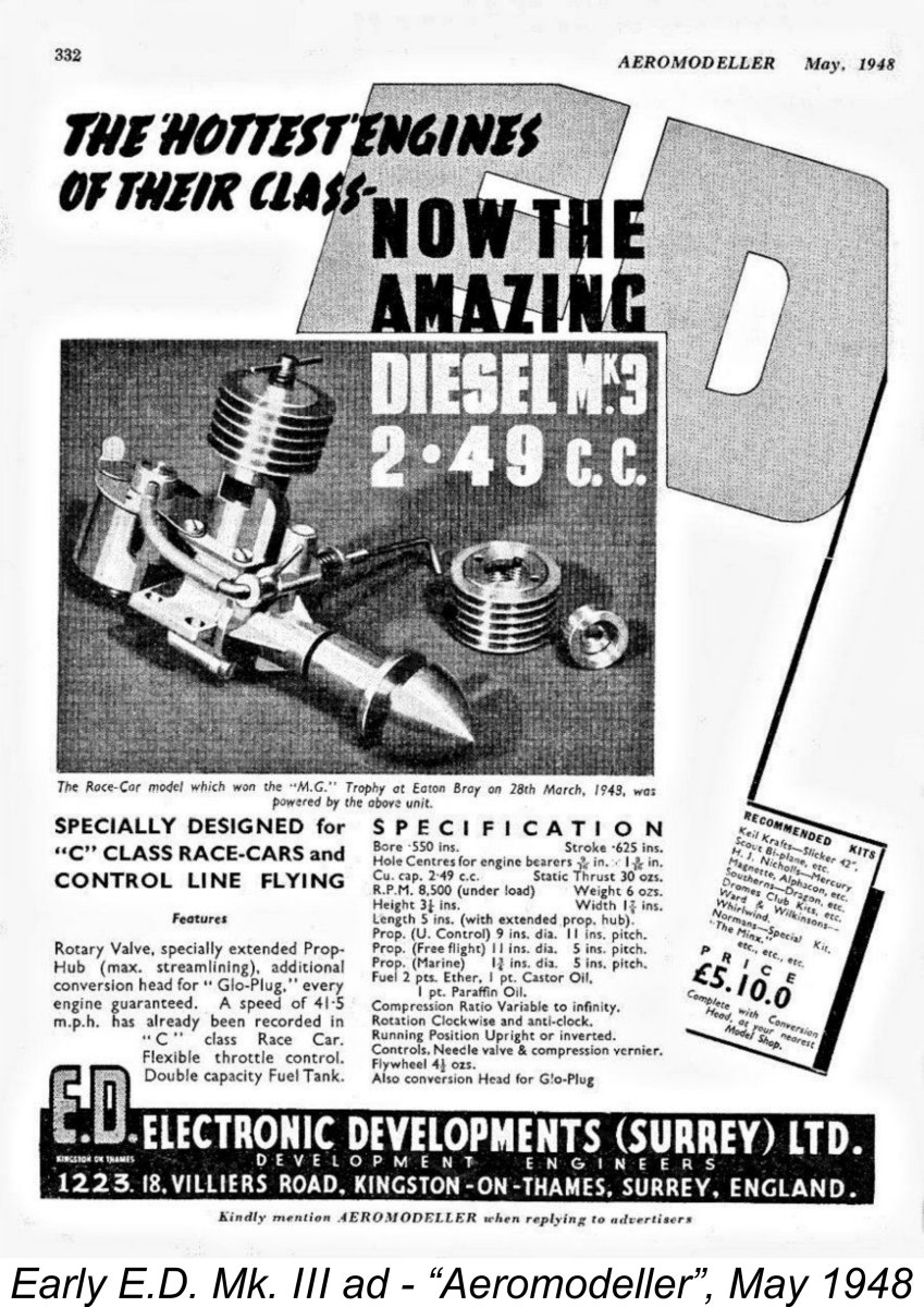
Moreover, E.D. advertisements made much of the fact that an example of the new model was used to power the tether car which won the MG Trophy at the Eaton Bray meeting of March 28th, 1948, establishing a new 2.5 cc World Record of 41.7 mph (67.1 km/hr) in the process. It thus seems certain that the Mk. III first appeared on the market in early March 1948.
Nicholls made much of the claim that he had "scooped" all of his competitors by becoming the first dealer to add the E.D. Mk. III to his list of available engines. The Mk. III was featured in its own box in the advertisement along with the Comp Special and Mk. II. A great deal of emphasis was placed on the fact that the engine was supplied complete with a glow-plug conversion kit, with the note that it was the first British engine to be supplied with such a capability. The quoted price was £5 10s (£5.50). The announcement of the glow-plug conversion kit was in itself quite remarkable. The commercial miniature glow-plug had first appeared as then-recently as November 1947 on the American market. The fact that E.D.'s glow-plug conversion of their new Mk. III model was introduced in March of 1948 represents an amazingly quick reaction on the company's part. For convenience in identifying the different variants of the engine which successively made their appearance, we’ve elected to identify these variants as different numbered Types, just as we've done with the 2 cc sideport models. It must be noted that these Type numbers are ours alone - they were never assigned by the factory.
If the early factory promotional image seen at the left is anything to go by, the needle valve on the earliest examples differed from that used on later units. The thimble was tensioned by an external coil spring as opposed to the internal spring used later. Moreover, the fuel spigot tube emerged centrally from the other end of the spraybar in a coaxial direction, being bent after its emergence. It was this version of the engine that was featured in both the Henry J. Nicholls advertisement of April 1948 and the E.D. placement in May The glow-plug conversion kit supplied with each engine included a head button which could be installed to replace the diesel’s contra-piston. This button was centrally drilled and tapped to accept a standard short-reach glow-plug. The kit also included a different cooling jacket having a larger central hole to clear the plug. The provision of this conversion kit as standard equipment gave the E.D. Mk. III the distinction of being the first-ever purpose-built commercial British glow-plug motor, just as claimed by Nicholls in his April advertisement. This initial version only lasted for 2-3 months. Known examples include engines bearing the serial numbers 3C/50/8, D3/65/8 (an ex Col. Bowden example), D3/397/8, D3/731/8, E3/166/8 and E3/430/8. These numbers confirm that at least 731 examples were made in April 1948 and a minimum of 430 Type 1 units in May 1948, implying the company's anticipation of a strong demand.
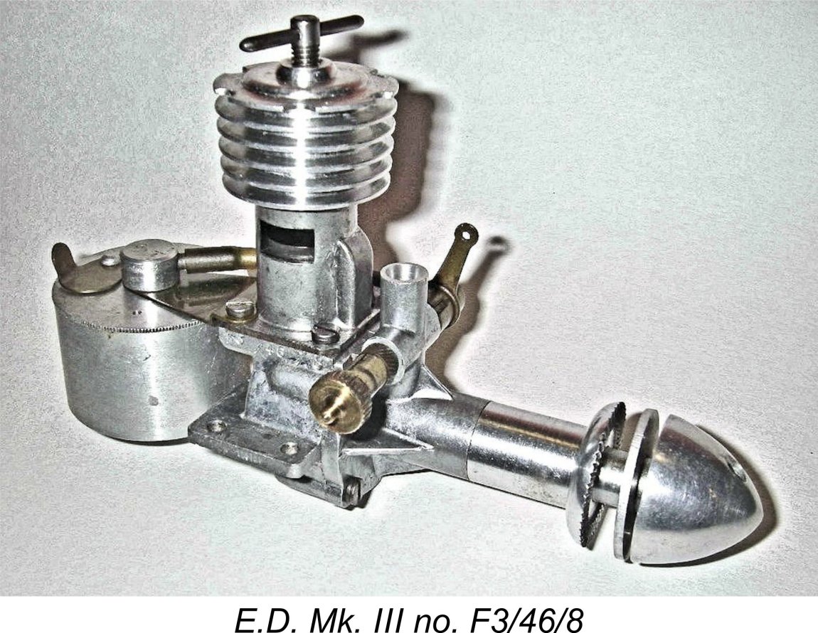
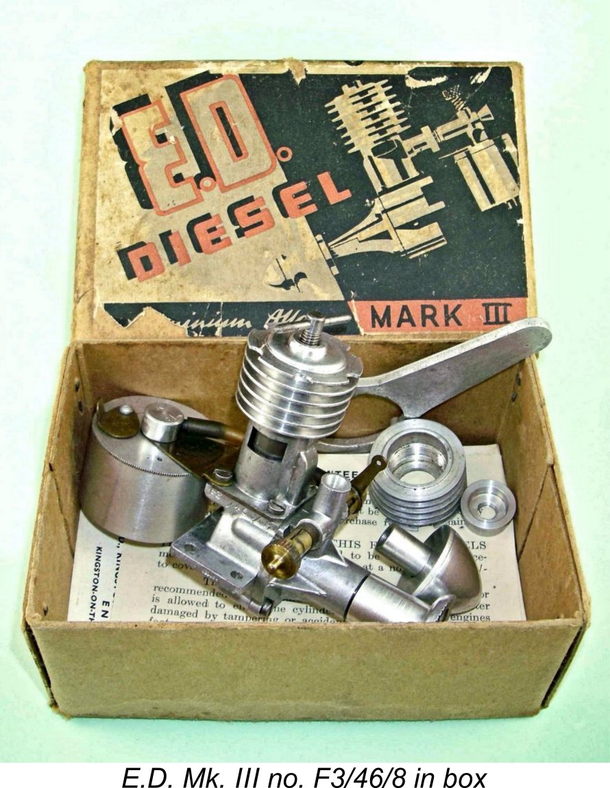
A special wrench was supplied with each engine to facilitate tightening. In addition, an unusually detailed instruction manual was included with each engine. The entire package was supplied in a sturdy and clearly-labelled cardboard box. This variant is designated as the Type 2 in our identification protocol. The higher-numbered E-series engines from May 1948 such as previously-illustrated E3/560/8, E3/675/8 and E3/771/8 are of this type, while reported serial numbers of similar engines from June 1948 include F3/46/8, F3/130/8, F3/335/8, and F3/377/8. These numbers confirm that at least 771 examples of the Mk. III ended up being made in May 1948 and a minimum of 377 examples in June 1948. These are quite significant figures. At this stage, demand for the engine must have been quite high. I've been asked by a number of people why E.D. never modified the companion 2 cc Comp Special's jacket to accept the same kind of wrench. The answer is undoubtedly the fact that no glow-plug conversion of the Comp Special diesel was ever offered by the factory. The required degree of tightness of the jacket installation on the diesel Comp Special could be achieved quite readily without the use of a special tool. It was only the need for the glow-plug conversion head to be really well tightened on the Mk. III cylinder that necessitated the provision of a wrench for the larger model. Production clearly continued at a healthy level during this period. It must be remembered that E.D. were also producing both the Comp Special and the Mk. II in substantial numbers at the same time, so the machine shop at Villiers Road was kept very busy! Indeed, they were soon to become even busier thanks to the August 1948 introduction of the best-selling 1 cc E.D. Mk. I Bee. In June 1948 something rather strange happened. It appears that E.D. had begun to entertain thoughts of incorporating a bearing insert of some kind at the rear of the main bearing. There was already talk of the addition of a roller bearing at this location. This would necessitate an increase in the diameter of the front housing. At some point in June 1948 the Mk. III began to feature a front main bearing housing having an external diameter of 0.637 in. as opposed to the former 0.560 dia. component. However, despite this increase the bearing remained plain, at least at this time, although some examples received a steel thrust bearing at the rear. The rest of the bearing remained unbushed as before. The outside diameter of the prop driver's rear shank also remained unchanged, meaning that it no longer matched that of the main bearing housing.
In December 1948 the long-promised and previously-discussed roller bearing finally made its appearance, resulting in what we’ve elected to call the Type 4 variant of the engine. However, some engines from that month’s batch (like that illustrated here) continued to feature the plain bearing, probably to use up components already on hand. From that point on until the engine’s withdrawal in late 1950, this was the standard form in which the Mk. III was sold. Initially, the large-diameter all metal tank was retained, although some later examples had the brass tank mounting bracket stiffened by the inclusion of two pressed-in flutes running fore and aft. The last examples had the red plastic tank as fitted to the Comp Special, although this was not suitable for use with glow fuel. Engines incorporating the roller bearing include numbers 3N/10/8, 3N/394/8, 3C/76/9, 3D/211/9, 3E/161/9 (red tank), 3F/27/9, 3J/133/9 and 3K/55/9 (red tank). It’s clear that at least 400 or so examples were still being made monthly as of December 1948. The use of the red plastic Comp Special-type tank seems to have become general in the latter part of 1949. It’s perhaps inevitable that examples are encountered which don't quite fit in the above taxonomy. For example, D3/397/8 from April 1948 should not have the semi-circular cutouts in the cooling jacket’s top fin, but does. In addition, it should have the small-diameter main bearing housing, but doesn’t! There’s also 3N/233/8 from December 1948 which theoretically should have a roller bearing crankshaft, but doesn't! Well-used engine number D3/397/8 could be explained as having been assembled by a former owner from an assortment of components, although matching marks of long-ago use running across component interfaces suggest that the engine was in service in its present state for quite some time. Regardless, such hybrid examples are likely not uncommon. Engine number 3N/233/8 is more difficult to explain, since it appears to be new and little if at all used. It’s possible that E.D. ran short of roller bearings but still wanted to produce additional examples for the 1948 Christmas rush, accordingly quietly assembling some units at random without rollers. We'll never know. It's unlikely that any owners would have noticed ................ There seems to be little doubt that for a time at least the Mk. III rode the crest of a wave as the most powerful British production diesel in its displacement category. Following its introduction, the engine enjoyed a period of considerable competition success, both in model aircraft and model cars. However, model engine design was in a rapid development phase during this period, and any performance edge which the Mk. III may have enjoyed was not to last long. By mid 1949 the Mk. III was being seriously challenged by a number of other designs from other makers, most notably Aerol Engineering with their Elfin range and the ultra-light and powerful AMCO 3.5 PB model. E.D. initially met these challenges with the previously-illustrated disc rear rotary valve (RRV) Mk. IV 3.46 cc model (later christened the “Hunter”) which appeared in late 1949.
In the following month of April 1951 the company announced the Mk. III’s replacement, the famous E.D. Mk. III Series 2 “Racer” which was destined to become one of the most popular and successful 2.5 cc diesels of the 1950’s and beyond. However, it’s almost certain that actual manufacture of the old Series 1 Mk. III had ceased long before this time. Certainly, no more was heard of the engine after this date. Based on known serial numbers, the peak production period for the original Mk. III was April to December of 1948 (nine months) with an estimated average of 500 engines per month being produced. The peak so far recorded for this period is at least 675 units in May. This suggests a total production of around 4,500 units during 1948. Production remained fairly high for the first few months of 1949, with at least 211 examples still being manufactured in April of that year. Even as late as September 1949, over 133 examples were manufactured, implying a further production of some 1,400 examples during the first nine months of 1949. However, nearly all reported batch numbers after September 1949 are two figures, implying that demand had fallen sharply as 1950 approached. It seems unlikely that total Mk. III production reached 7,000 units. This is a very low figure by E.D. standards, implying that the Mk. III was perhaps the least commercially successful design produced by the company during its early years. The E.D. Mk. III Sideport Model
Beginning during the first half of 1949, E.D. actually went so far as to produce a handful of what amounted to E.D. Comp Specials fitted with the bigger-bore Mk. III piston/cylinder sets. This might be viewed as the Type 5 variant of the E.D. Mk. III. These sideport models used the standard Comp Special crankshaft, front housing, prop mounting hardware and fuel supply assembly. They looked exactly like standard Comp Specials unless one noticed the slightly larger cylinder and cutaway-equipped cooling jacket. Naturally, the mounting boss for the sideport induction assembly was restored on these examples. The cases used to construct these units were necessarily Mk. III components, since the Mk. III’s increased bore required a change in the pitch circle diameter of the cylinder mounting screws. However, the beam mounting holes for the Mk. III case are identically spaced to those of the Comp Special, since the two designs are based upon the same casting and share the same stroke. Accordingly, the Mk. III sideport variant (and the FRV model for that matter) could be bolted directly into a model originally built for the Comp Special (or Mk. II). The sideport Mk. III was built on the Mk. III crankcase using a standard Comp Special crankshaft running in a pressure die-cast Comp Special front housing with “E.D.” and “Mk. III” cast onto the top and bottom faces of the housing respectively when viewed from the front. This is evidence that E.D. saw the sideport Mk. III as a potential production engine, although in the end it was never advertised. The same front housing appeared on Comp Specials with the last I of the III identification neatly removed, although occasionally E.D. were lazy and forgot to do this. It’s likely such unintentional omissions which account for the odd Comp Special appearing on eBay as a sideport Mk. III! Buyer beware ..........
Reported serial numbers for this variant from mid to late 1949 through 1950 confirm that production numbers were indeed very low. Since this variant never received its own model identification letter, it seems evident that the sideport models were numbered in sequence with ordinary rotary valve Mk. III's, probably being produced only to special order by pulling a standard FRV Mk. III out of the line and retro-fitting it with the sideport components. Production continued at some level into the latter half of 1950. Reported serial numbers for the sideport Mk. III include 3D/158/9, 3J/10/9, 3J/12/50 and 3K/69/50. Towards the end of all Mk. III production, likely in late 1950, E.D. experimented with a ball-race version of the Mk. III side-port. This featured a single ball-race at the inboard end of the crankshaft. Such a bearing could be used in this model due to the smaller diameter of the Comp Special shaft. Since only one example of this variant is know to exist, currently residing in Kevin Richards' enormous E.D. collection, it's apparent that this variant never progressed beyond prototype status. Kevin's example bears the serial number 3G/11/50, dating it to July 1950. It’s actually impossible to tell from an external examination that this engine is equipped with a ball-race, but internal inspection removes all doubt. The front housing is a modified Comp Special component, while the crankshaft appears to be a standard Comp Special item. The smaller diameter of the Comp Special shaft is what makes the use of a ball-race possible. Overall, this example appears to represent a factory experiment aimed at improving performance. The E.D. Mk. III on Test By E.D.’s own account, the standard FRV Mk. III wasn't that much more powerful than the 2 cc Comp Special. The company gave the maximum static thrust for the Mk. III as 26 ounces compared to 23 ounces for the Comp Special. The Mk. III also acquired a reputation for being somewhat trickier to start and adjust than the Comp Special. This creates the expectation that we’re looking at a small power increase from a bulkier, fussier and more expensive engine, all of which may help to explain its comparatively short production life of around 2½ years. The sole published review of the E.D. Mk. III appeared rather belatedly in the April 1949 issue of “Aeromodeller” magazine. This review more or less coincided with the commencement of the downward spiral in the engine’s popularity which is indicated by the serial numbers - the heyday of the Mk. III had already passed. The "Aeromodeller" test of the E.D. Mk. III was the twelfth such review presented by Lawrence H. Sparey. It injected a little confusion into the issue of the test engine’s physical description. The photographic illustration shows a large-diameter main bearing housing, while the text cites the presence of a roller bearing at the rear. This looks like a standard Type 4 engine, which would be correct for early 1949. Indeed, a close examination of the photograph included with Sparey's report confirms that it was from the A batch of January 1949 - the rest of the number is undecipherable, but the figures 3A are perfectly clear. Fair enough, but the accompanying 3-view drawing shows an engine having the smaller-diameter main bearing housing, while the sectional view omits the roller bearing. It appears that the engine drawn by the artist was a Type 2 example as opposed to that actually tested by Sparey. Sparey noted that the Mk. III had been designed primarily for use in Class “C” tether cars and control-line models. He praised the engine’s long prop driver, which kept the fuel mixture control well clear of the prop disc. He experienced a little trouble with the needle setting tending to vibrate out of its established position, but this was cured with the use of a firmer locking arrangement. There remained a reported tendency for the engine to “hunt” (run inconsistently) at the higher end of the tested speed range (above 9,000 rpm, which was well above the engine’s measured peaking speed), but the use of Mercury no. 3 fuel as recommended by the manufacturers apparently did much to mitigate this characteristic. The engine was pushed up to over 13,000 rpm despite the fact that it delivered its peak output at around 7,800 rpm. This highlights a repeated failing on Sparey’s part in his capacity as an engine tester - he consistently pushed engines up to speeds well beyond their peaks and then complained about any problems to which this treatment gave rise, as in the present instance with the high-speed “hunting”. Why any tester would do this defies explanation - all that it did was subject the engine to stresses and operating conditions for which it was not designed and to which it would not normally be exposed in service. One consequence of this treatment was the failure of the sheet brass fuel tank mounting bracket. This occurred when the poor old engine was pushed up to a speed of 13,000 rpm, some 5,000 rpm past its peak! Although my own experience confirms that this bracket is subject to fatigue failure through protracted use at “normal” speeds, it’s scarcely fair to criticize the engine for failing under the conditions to which Sparey subjected it. Sparey reported that the engine was hand-started throughout the test. Presumably he had no trouble in this regard since no difficulties were mentioned. Once the problems of the needle lock and fuel mixture were resolved as noted earlier, the engine ran steadily at all speeds up to around 9,000 rpm, at which point the “hunting” behavior asserted itself. Since this was well past the engine’s peak, it’s unclear why this should be presented as an issue in the report.
My own test of unmodified Mk. III no. 3N 233/8 some years ago pretty much duplicated Sparey's findings. I measured a slightly higher peak of 0.136 BHP @ 8,100 rpm, but the shape of the power curve was more or less identical - just a fraction more power. I also found that the cut-out worked perfectly. Sparey’s overall summation was that “the E.D. Mk. III seems to be well and strongly made as, apart from the breakage of the flexible tank mounting, no other troubles were experienced during a long and severe test”. Next time, Lawrence, try a sledge-hammer ..........
This example is far from stock. It has had a cut-away formed very neatly in the front of the lower piston skirt to improve gas access to the bypass passage at and around bottom dead centre. This work was carried out by a previous owner - it was in this configuration when I acquired the engine many years ago. It was also in well-used condition at the time when I acquired it. Since the engine wasn't in pristine original condition anyway, I decided to go all the way! Noting that the FRV induction system closed at only around 15 degrees past top dead centre, I decided that a considerable improvement should result from an increase in the very short sub-piston induction phase. I turned 0.020 in. off the base of the piston skirt to increase the sub-piston induction period to around 40 degrees (20 degrees each side of top dead centre). In addition, anticipating that the long stroke and still-heavy piston would likely give rise to significant vibration at the higher speeds for which I was hoping, I ground two wedge-shaped segments off the crankdisc rim, one on each side of the crankpin, to impart some counterbalance to the shaft.
For this test, I used a standard diesel fuel with 1½% ignition improver and 28% castor oil, the latter aimed at protecting the rod bearings. Having had plenty of previous running, much of it in the air, the engine required no break-in - I got stuck in right away, using an APC 10x6 prop for the initial runs. Contrary to its somewhat chequered reputation, the modified engine proved to be an excellent starter and a superb runner. Even the needle valve belied its legend by being both responsive and progressive in operation. The Mk. III liked a few choked flicks followed by a small prime - choking alone was less effective. It also liked the needle to be opened half a turn from the running setting for a cold start. However, it proved to be an unfailingly good starter using the appropriate procedures. On the faster props it would start and run at the running settings. Running was extremely smooth at all speeds tested - the engine displayed no tendency to "hunt" at any time. Both the needle valve and comp screw held their settings securely throughout. This situation was doubtless helped by the fact that vibration levels remained well within acceptable limits even at speeds in excess of 10,000 rpm. The counterbalancing modification to the crankdisc along with the removal of a little weight from the piston appeared to have met expectations completely in minimizing vibration. So far, it's all good news! Happily, the news now gets even better - in performance terms, the modified engine simply buried both Sparey's test unit and my own previously-tested unmodified example. Check out these figures, which I'm happy to repeat for any doubters who might drop in!
As can be seen, the modified engine peaked at around 9,900 rpm, at which speed it was developing around 0.194 BHP. This is far more like the level of performance that we would expect from an engine having as well-developed a crankshaft rotary valve as this one. The very timid use of sub-piston induction Looking at these results, I confess to a feeling that E.D. really missed a golden opportunity with this engine. If it had been released in early 1948 with the levels of performance which I measured, it would have been viewed as perhaps the top-performing Class A diesel of its day. It would also have remained competitive for a considerably longer time. The modifications which are featured in my example could easily have been incorporated into the production version at minimal additional manufacturing cost. The extent to which these simple modifications improved the Mk. III's performance seems to me to constitute a persuasive piece of evidence to refute the idea that Basil Miles had much if anything to do with this design. Surely a designer of Basil's calibre would never have missed such readily-apparent opportunities!
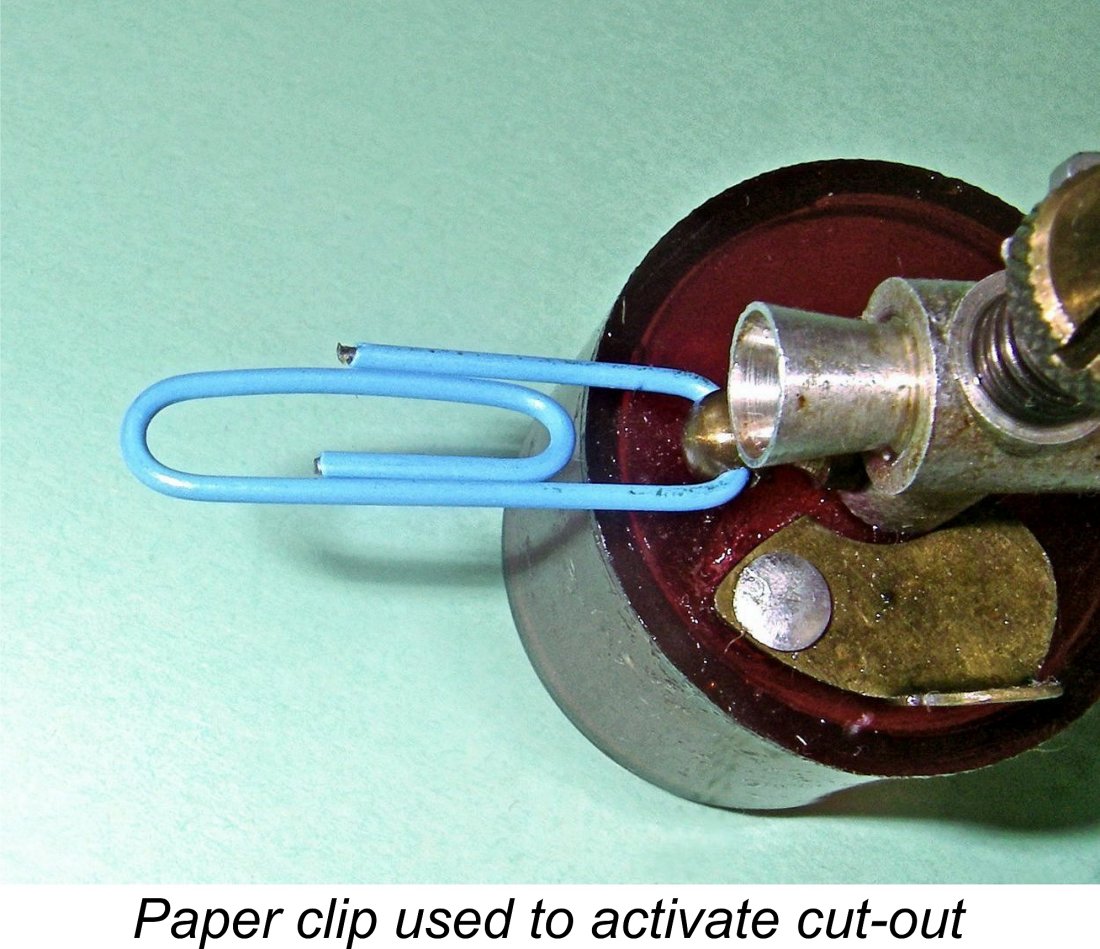
I set it up in the test stand, intending to give it a few break-in runs and then take some spot-check speed readings. I used the same fuel and props as used for the previously-summarized modified Mk. III test conducted earlier on the same day. The sideport engine was clearly in need of some freeing-up, but I didn't want to expend too much fuel and operating life on this process given the fact that I don't plan to use the engine in a model. I contented myself with running four tankfuls through the engine on the APC 10x6 prop, keeping the needle on the rich side but leaning out at the end and then allowing complete cooling in accordance with my usual break-in procedure. Thereafter, my procedure for Speaking of the cut-out, this engine is fitted with the later spring-loaded plunger cut-out which first appeared on the Comp Special in 1949. Operating it on the bench is a bit tricky unless you plan ahead - the ball end of the plunger is really hard to grip. My method is to insert the outer end of a paper clip into the transverse hole drilled through the ball end of the plunger at the rear. This creates a perfect finger-grip for pulling the plunger back to stop the engine. The cut-out worked instantaneously evey time - even Lawrence Sparey would have got this one to function! Its use greatly facilitated the testing.
The engine proved to be a useful enough performer, although it showed itself to be very little more powerful than the 2 cc Comp Special on which it was based. It seems to me that it could have used a slightly larger intake area than the standard 2 cc component actually fitted. Even so, it wasn't all that far short of the figures measured both by Sparey and myself for the unmodified FRV version of the Mk. III. The following data tell the story.
It seems readily apparent from these results that changing from FRV to sideport induction with the Mk. III made far less difference to the performance than might be expected. To me, this says that the limiting factor in performance terms was not the means of induction, but rather the extremely constricted bypass arrangements which were common to both sideport and FRV versions of the engine in unmodified form. Both variants would have been immensely improved through attention to this issue - the results achieved with my modified FRV unit confirm this beyond argument. Based on these test results, it's pretty easy to understand why the sideport Mk. III never progressed beyond "special order" status. It really offered no significant performance advantage over the 2 cc Comp Special and certainly fell short of its more common FRV relative, although less so than we might have expected. It would have appealed only to die-hard traditionalists who just liked using sideport diesels. I'm still in that camp myself .........!! Repair of Soldering Joints
The principle behind the creation of such linear soldering connections is the tendency of molten solder to "wick" along the joint due to surface tension. This may best be thought of as "sweat soldering". In the case of the Mk. III, Maris and I have both more than once seen cracks develop between the base of the bypass cover and the cylinder flange or even the cylinder itself. In the case of a Mk. III recently acquired by Maris, a previous owner had a go at repairing such a crack using a soldering iron, but had left a spot near the corner uncovered, creating a serious crankcase leak. Maris points out that a soldering iron is far from ideal for this sort of thing, as it risks the whole cover popping off by the time enough heat is transferred to finish the job. If that happens, you have to devise a jig to hold the cover in position while re-establishing the gas-tight soldered joint. (I've done this several times myself - Ed.) A butane micro-blowtorch does a far better job, since it provides high heat in a very localized area. The trick is to get the spot thoroughly cleaned and prepared with (real) liquid acid-zinc flux, as opposed to the solder or flux used for electrical work. Then heat it until the existing solder melts in the spot of interest. All going well, it will wick into the crack or void and you're done. If not, clean more thoroughly and repeat, with a little added solder if needed. Work fast, and if not satisfied let it cool and have another go, rather than letting the heat travel to where it is not wanted. Maris's attached before-and-after images should clarify the desired result. He prefers a nice rounded fillet and tin/silver solder, rather than plumber's lead/tin, for added strength. My sincere thanks to Maris for sharing his experiences. Conclusion In my personal opinion, the E.D. Mk. III represented just one of a number of golden marketing opportunities which were squandered by E.D. over the years for whatever reason. As originally designed, the engine performed at a level which was little better than that of a good example of the Comp Special. It was also heavier, bulkier and more expensive. With its FRV induction, it really should have been a far stronger performer.
As it was, the E.D. designers unaccountably failed to spot these very obvious opportunities for improvement. Consequently, the Mk. III as originally released was a mediocre performer at best, offering a minimal performance advantage over the Comp Special and other competing designs. It's really hard to understand how, having created a design with such potential, E.D. managed to squander that potential to the extent that they did. Despite this failure, the Mk. III remains a well-built and very useable model diesel having a character and a charm all of its own. A little attention to a few details which were overlooked by E.D. and it becomes a top performer by 1948 standards. I would never advocate modifying a really nice example of any original antique engine, but if you have one like my "flyer" example that has already been nobbled and has kissed terra firma a few times, making those few changes will yield an engine that will serve you well. It will always remain one of my own favorites! _________________________ Article © Adrian C. Duncan, Coquitlam, British Columbia, Canada First published on MEN November 2007 This comprehensively revised version first published December 2021
|
||
 This is a comprehensive re-draft of an
 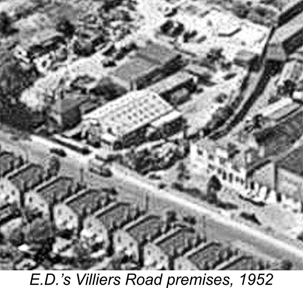 The registered name of the original company which manufactured the E.D. model engine range was Electronic Developments (Surrey) Ltd., working initially from premises at 18 Villiers Road in Kingston upon Thames, Surrey. These premises were located immediately adjacent to the very large Vine Products (VP) wine bottling and distribution plant. The E.D. factory was housed in the prominent white gable-roofed rectangular building with multiple skylights. The rather elegant building to the right housed the VP offices. The black vehicle parked on the E.D. factory's frontage area may be the company's then-famous Ford delivery van.
 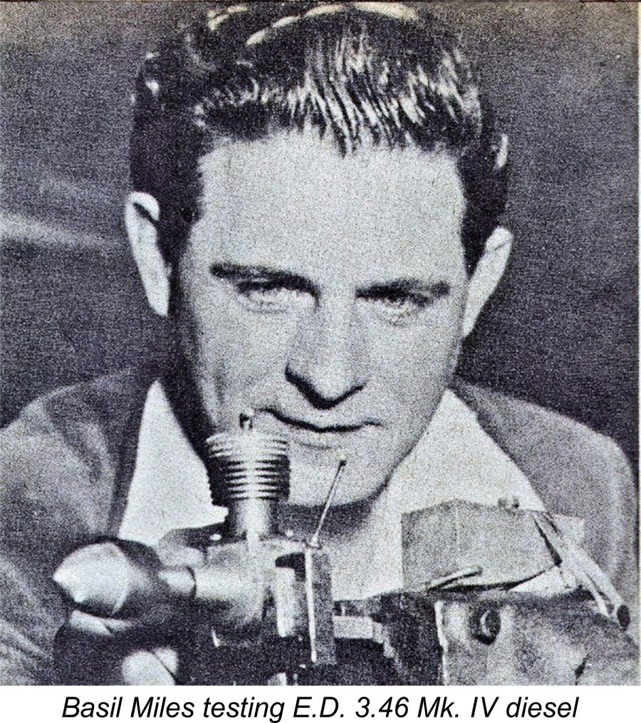 For one reason or another, the name of Basil Miles has become closely associated with E.D.’s first ten years as a model engine manufacturer. In the past it has been widely assumed that Miles was the chief E.D. engine designer from the outset, but this view appears to be somewhat questionable. For one thing, Kevin Richards’ in-depth research confirmed that Miles never held an official position with the company at any time, apparently working in a consultant capacity all along.
 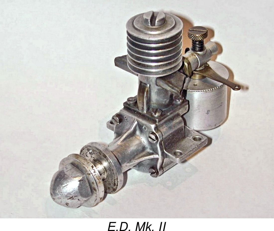 E.D.'s first national advertisement announcing the release of the Mk. II appeared in the March 1947 issue of “Aeromodeller” magazine. Thereafter, a variety of full-page advertisements for this engine appeared in “Aeromodeller” throughout the remainder of 1947, conveying the image of an enthusiastic, rapidly developing company that was very much “on the move”.
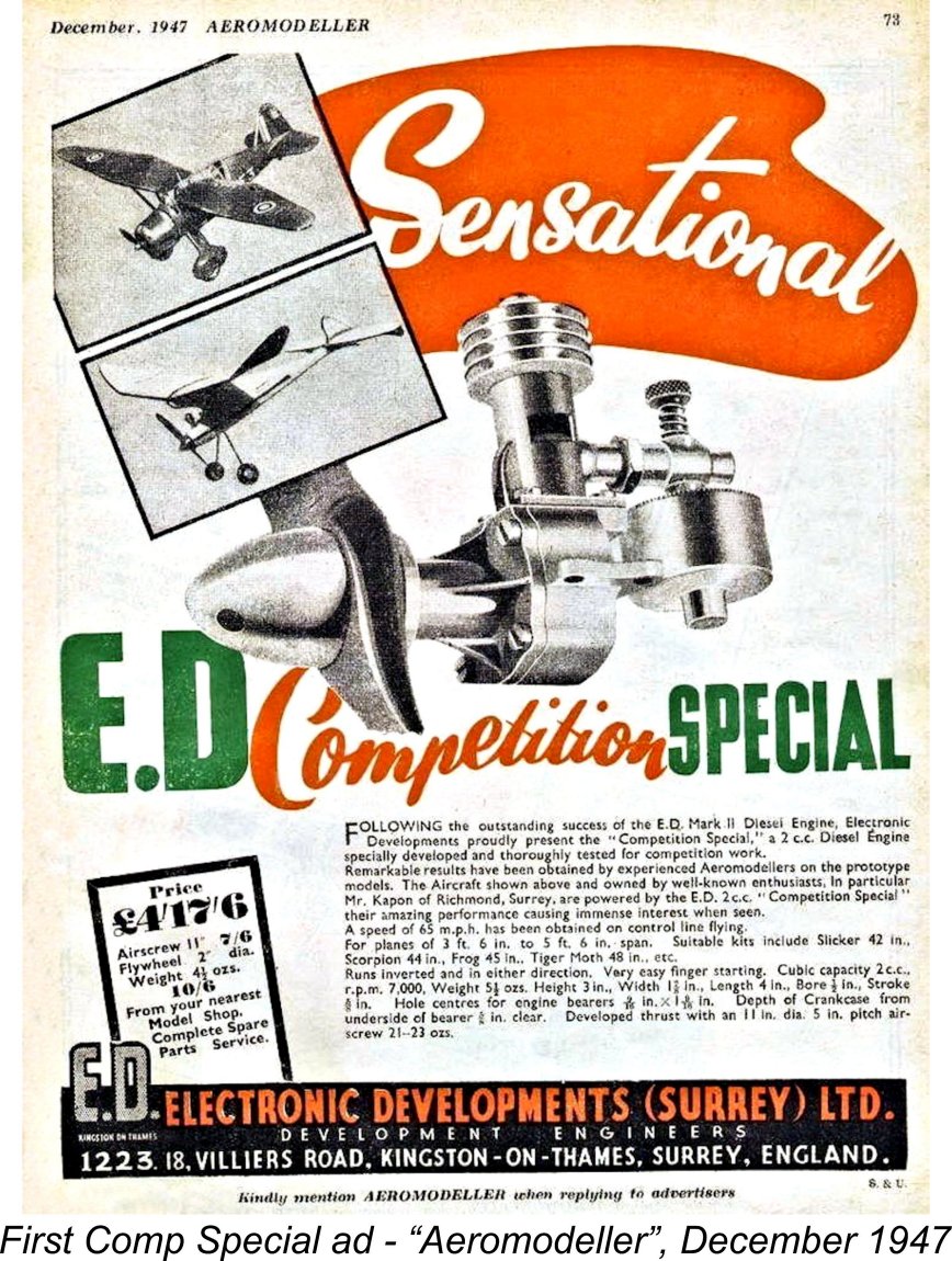
 The underlying design of the 2.49 cc E.D. Mk. III was clearly very much based on that of the existing 2 cc Comp Special model. The Mk. III featured the same stroke of 0.625 inches (15.875 mm), the extra displacement being obtained by increasing the bore from 0.50 inches to 0.55 inches (12.70 mm to 13.97 mm). This still resulted in a long-stroke engine.
 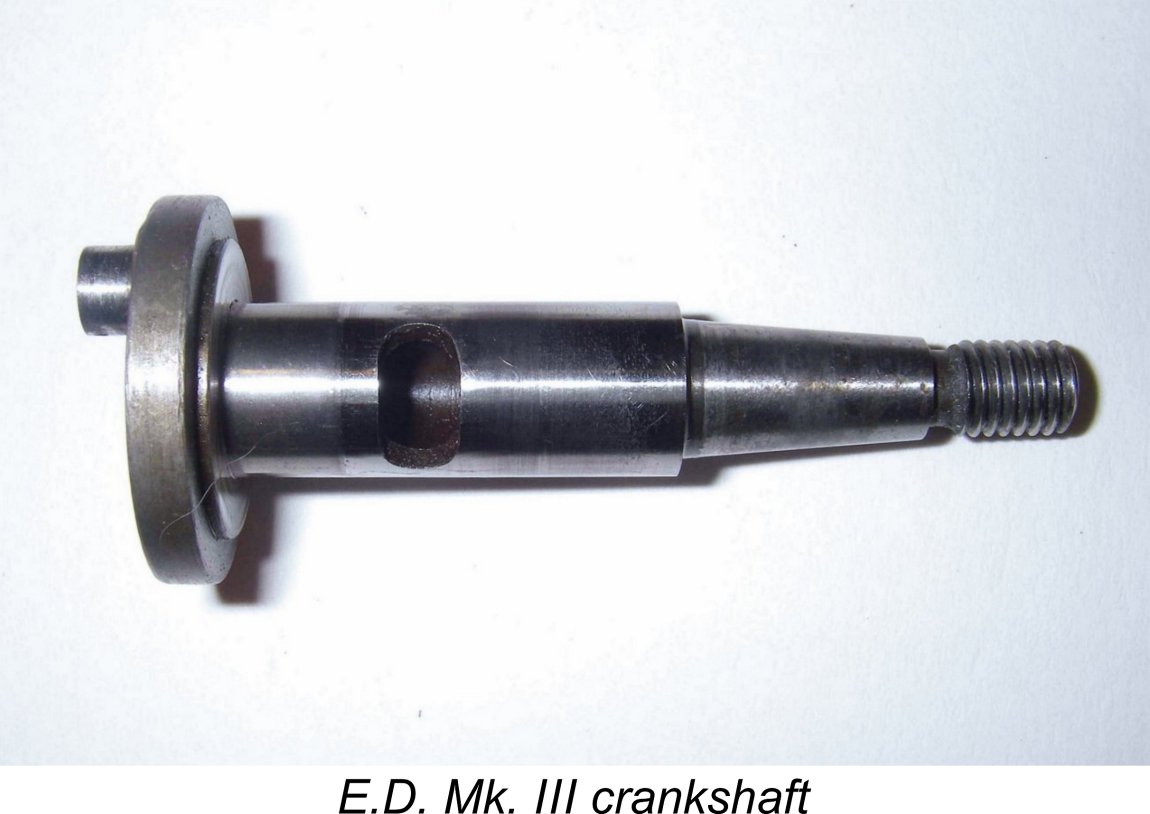 Unlike the bearings used in the Mk. II and Comp Special, which had cast iron bushings, the shaft of the Mk. III as originally released ran directly in the alloy of the front casting. This change was forced upon the makers by their use of a larger-diameter shaft running in the same basic housing - no room for the bushing! This issue was later addressed through an increase in the outside diameter of the main bearing housing, which allowed the use of bearing inserts of one sort or another.
 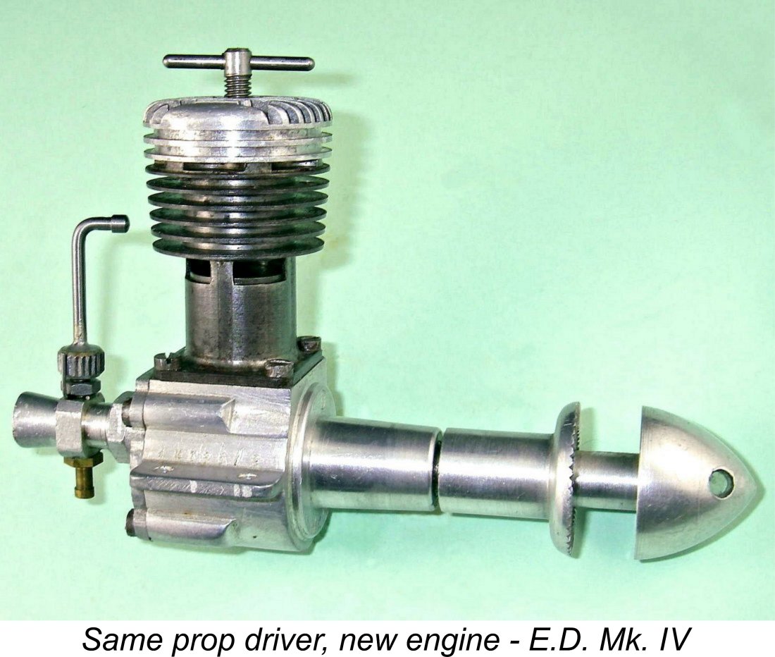 Another selling point was the use of an extended prop driver which placed the prop well forward of the cylinder and needle valve, also making cowling (then very fashionable) relatively straightforward. E.D. were to continue this concept with their later 3.46 cc Mk. IV model, actually using the same prop driver and spinner nut as featured on the Mk. III.
 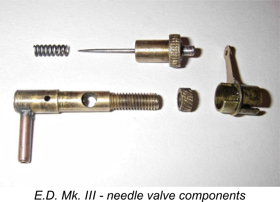 The spraybar was a complex affair, larger in diameter than the venturi opening and drilled through transversely at intake diameter so that when correctly installed the combination of the spraybar opening and the intake bore created a continuous passage of constant diameter. The fuel delivery end on all but the very earliest examples featured a separate soldered-in right-angle fuel nipple. A small inner tube was seemingly pressed into the spraybar bore on the delivery side to create a small jet nozzle which protruded into the venturi bore. This may be seen in the attached image of the spraybar components. Its effect would be to improve suction somewhat.
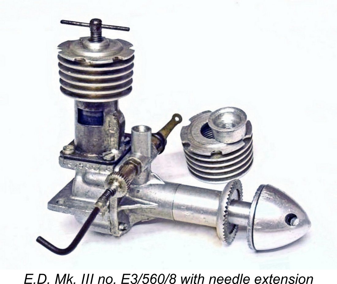 The outer end of the needle valve thimble was provided with a small-diameter spigot onto which a coil spring could be wound, with a needle valve control extension at the other end of the spring. This flexible needle valve extension may have been an optional accessory as opposed to original as-supplied equipment, since many NIB or LNIB examples are encountered without this extension, nor do their spigots display any evidence that one was ever fitted. Indeed, the majority of examples encountered today have no extensions - the one tested by Sparey certainly lacked this fitting. Illustrated engine no. E3/560/8 is a rare exception. Either they were not routinely fitted as supplied or owners typically removed them. Alternatively, they may have fallen off through vibration-induced metal fatigue or been wiped out in a crash.
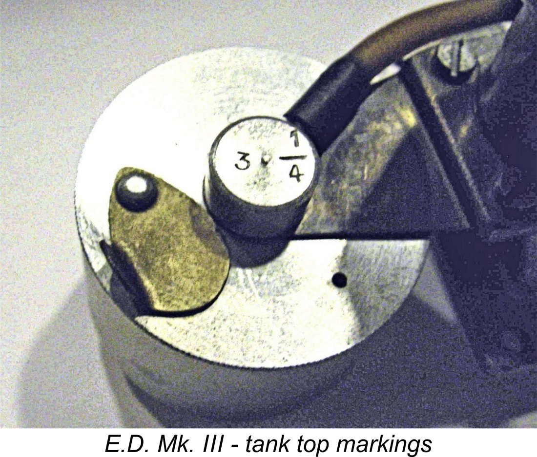 Sparey reported that the sheet brass tank mounting bracket on his example fractured during his tests due to the cyclic fatigue-inducing stresses arising from the vibration of the heavy tank set-up when the engine was running. However, he had pushed the engine well beyond its peak to achieve this unhappy result. On later engines, flutes were pressed into the tank mounting bracket for some added rigidity. Of course, many owners removed the tank for installation of the engine in their models.
 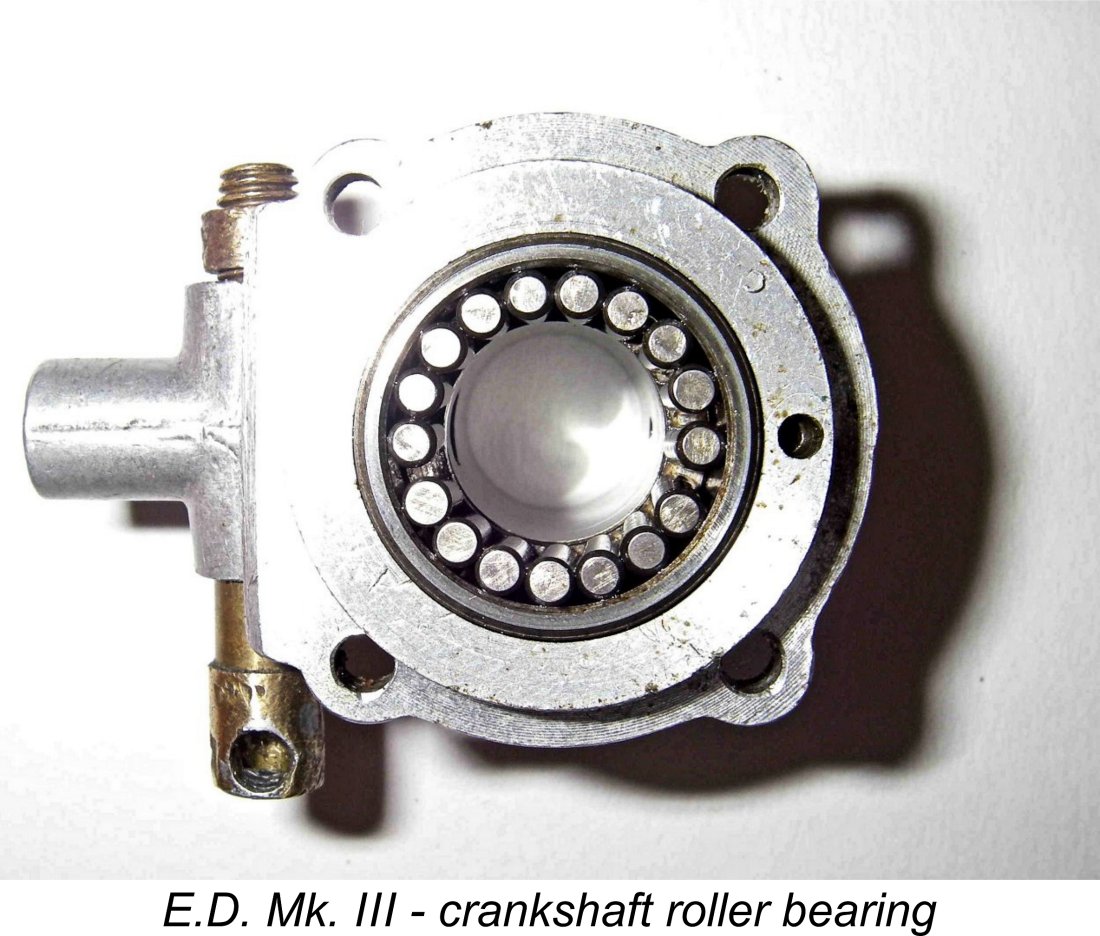 Perhaps the most significant and possibly controversial design change to appear during the production lifetime of the Mk. III was the late 1948 introduction of a roller bearing at the rear of the main crankshaft journal. This roller bearing featured 17 hardened and ground steel rollers running uncaged in a steel outer race which was press-fit into a recess machined in the front bearing housing.
 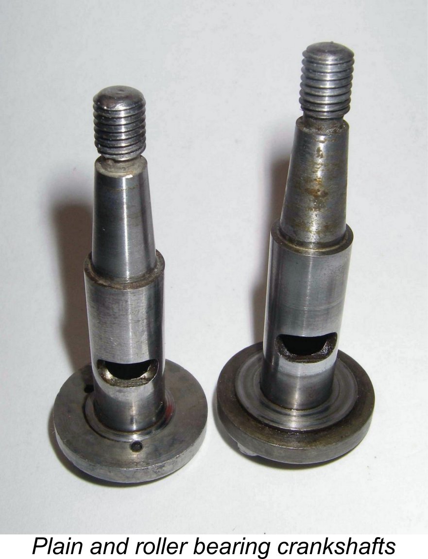 From the accompanying photo, it would appear that E.D. made two types of crankshaft for the Mk. III, but in reality they were more economical than that. The larger thrust-face seen on the right-hand shaft from a roller bearing example is actually a separate hardened steel washer, relieved on the rear face to sit over the standard shaft’s far smaller thrust-face which is visible on the left-hand shaft in the image. The fit is so close that given time and a bit of castor gum, the two can look like a single unit - I was fooled initially when first confronted with this set-up.
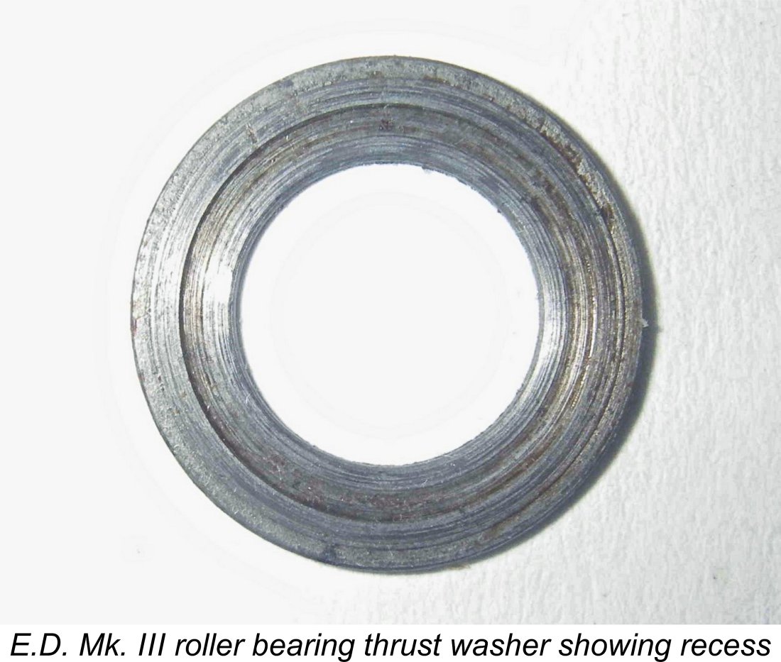 The end result of all this complexity was the creation of a large diameter and hence high velocity hard metal-on-metal sliding thrust bearing, along with a roller bearing carrying a high intermittent radial load in one direction only. A situation that most engineers would go far to avoid! The rest of the bearing continued to be a simple plain unbushed light alloy tube.
 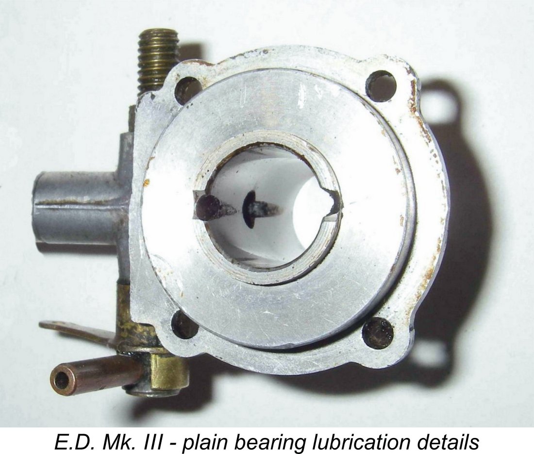 This would require hyper-accurate fitting of the shaft journal, rollers and outer race as well as the use of suitably hardened wear-resistant materials. Personally, I reckon that the original plain bearing design with its far lesser-diameter steel-on-alloy thrust bearing would be both more dependable and at least equally efficient. It would certainly be considerably less costly to manufacture.
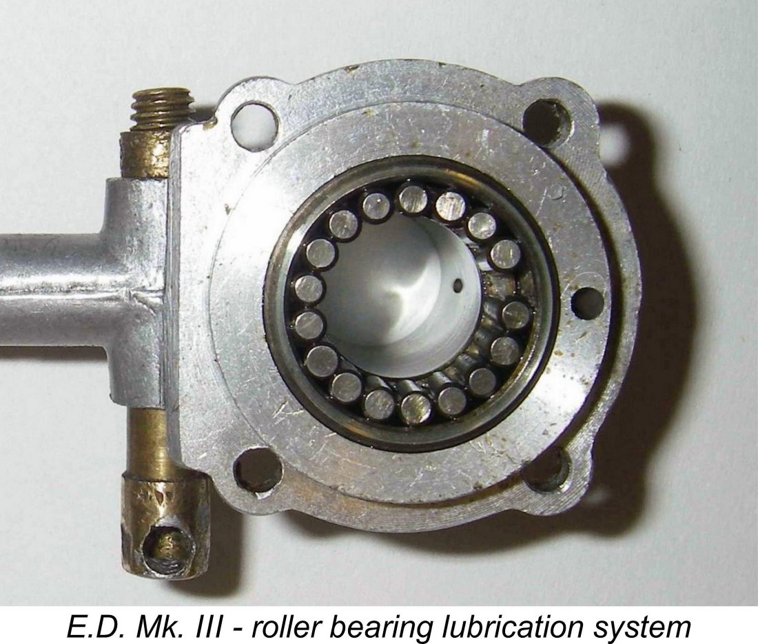 The roller bearing model has a very tricky long inclined oil passage drilled from the bottom of the inner face of the casting at an upward angle relative to the engine’s fore-and-aft axis so that it intersects the middle of the plain bearing area. This is visible in the accompanying photo once you know where to look.
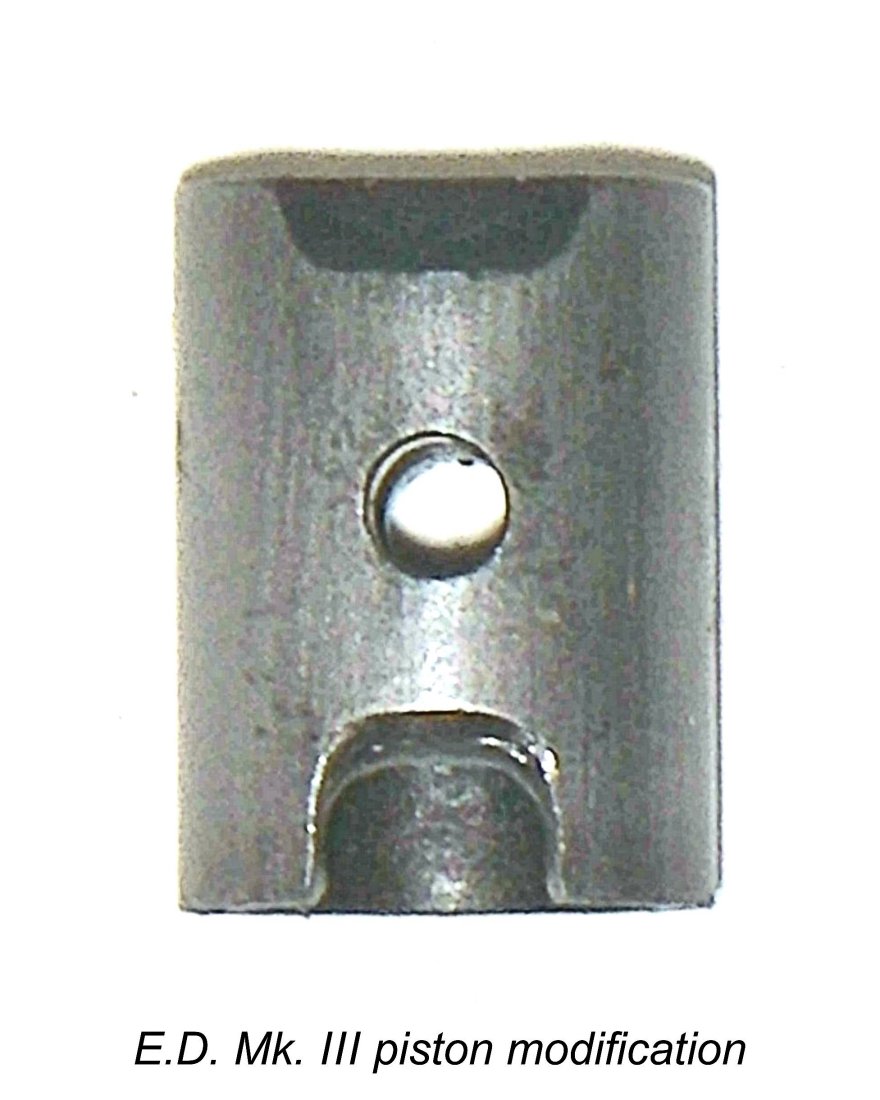
 The E.D. Mk. III appeared with no great fanfare in early 1948. Its initial appearance in an E.D. advertisement came in May 1948 - the engine was not mentioned in E.D.'s April advertising, which continued to feature the Comp Special and Mk. II. However, reported serial numbers confirm that the Mk. III had gone on sale prior to that date, because the earliest documented examples carry the batch letter C along with the year indicator 8, confirming production in March 1948.
 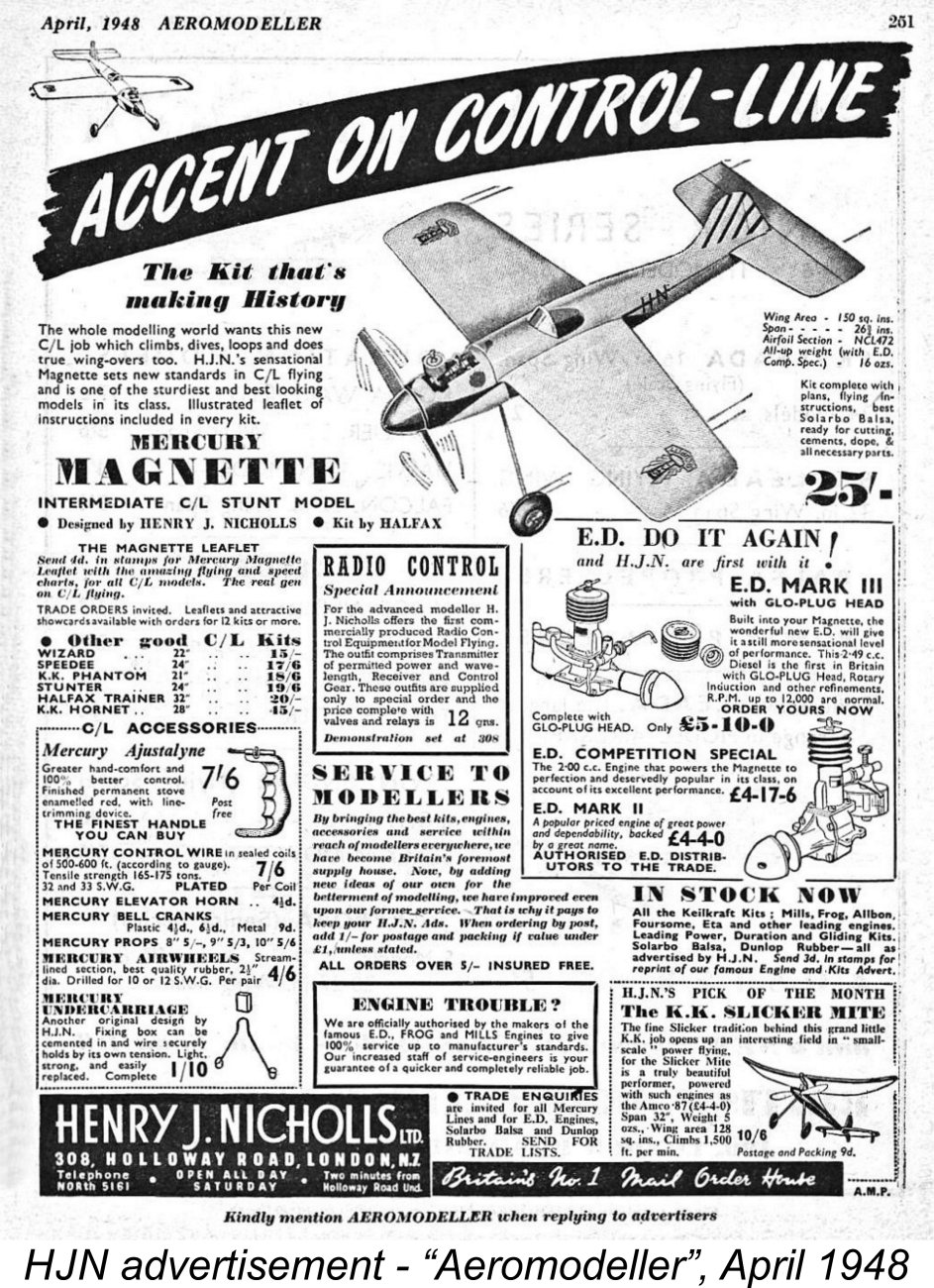 This impression is confirmed by the advertisement placed by Henry J. Nicholls in the April 1948 issue of "Aeromodeller" (which actually hit the news-stands in mid March). In order to meet the editorial deadline for the April issue (which actually appeared on the news-stands in the latter part of March), this advertisement must have been laid out in late February.
 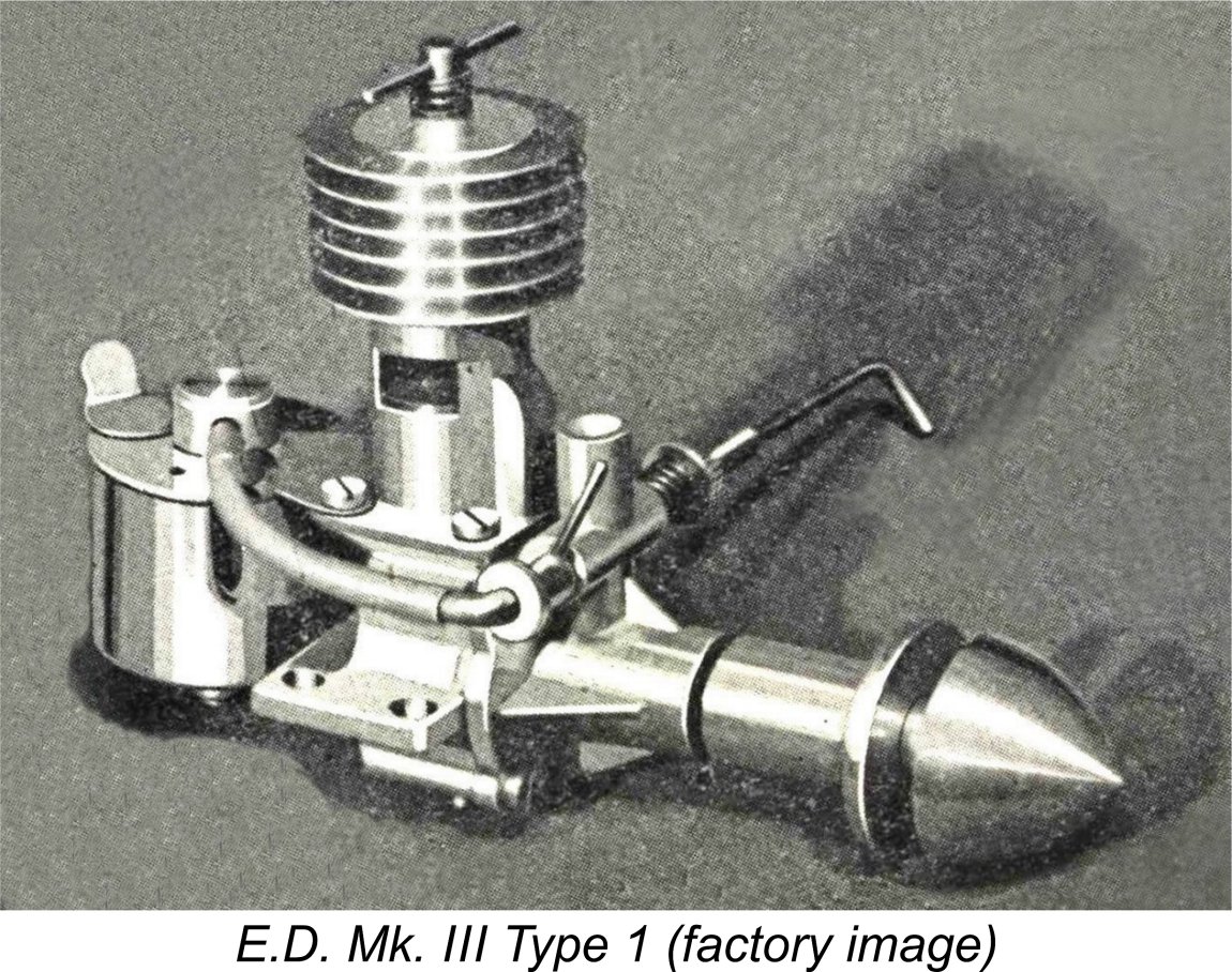 The initial variant which appeared in March 1948 was what we’ve designated as the Type 1. This featured a plain bearing for the crankshaft, with no insert - the shaft necessarily ran in the light alloy material of the front housing, since the larger-diameter shaft left no space to accommodate any bushings. The external diameter of the main bearing housing was the same as that of the extended prop driver shank at 0.560 in. The cylinder head was turned plain, just like that of the Comp Special, with no provision for the use of a tool in tightening it. The engine featured a large 1.5 inch diameter metal tank supported by a sheet brass bracket with no strengthening ribs.
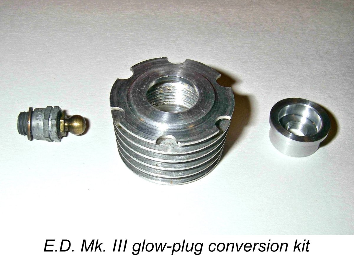
 At some point during May 1948, seemingly after the production of some 500 or so examples of the Type 1 variant during that month, a change was introduced to the cooling jacket. This change was almost certainly driven by the fact that the installation of the glow-plug conversion kit required that the glow-plug cooling jacket be screwed down really tightly to ensure a good head seal. To aid in achieving this, both diesel and glow-plug cooling jackets now featured a series of 6 half-round cutaways equally spaced around the circumference of the jacket’s top fin.
 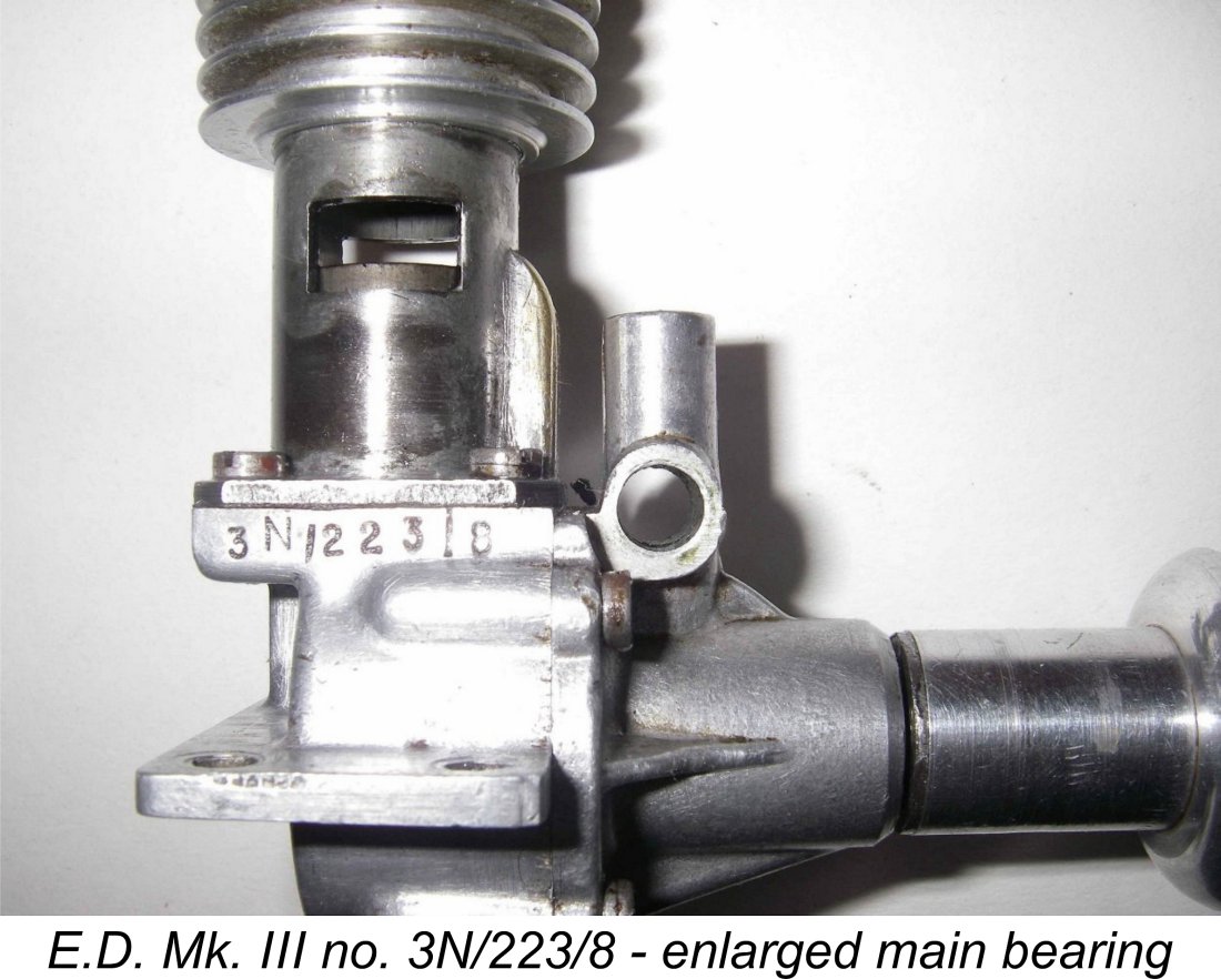 This is the Type 3 version of the engine in our classification system. Engines of this type seem to have continued as the standard issue for some time. Examples include engines bearing the serial numbers G3/55/8 and J3/48/8 going all the way down to 3N/223/8 from December 1948.
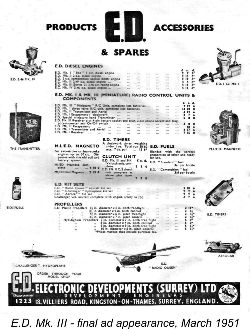 The Mk. III continued to appear in E.D.’s advertising throughout 1950, although it did not enjoy “star billing”, merely being listed among E.D.’s other products. As far as I can determine, the engine’s final advertising appearance came in March 1951. By this time the price had fallen to only £3 5s (£3.25), indicating that the company was now clearing old stock at "fire-sale" prices.
 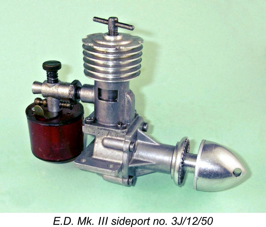 While the development and manufacture of the Mk. III was proceeding during 1948 and into 1949, its sideport E.D. Comp Special companion in the range was continuing to sell quite steadily. Even the Mk. II continued to attract its share of customers. This seems to have got E.D. thinking about the sales prospect of a slightly enlarged version of the Comp Special which would theoretically develop more power and torque.
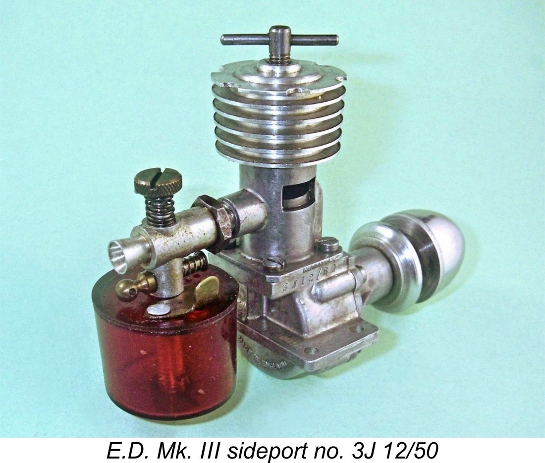 It appears that the sideport Mk. III was only ever available from the factory to special order. No specially-labelled box was ever created - the engines were sold in standard Mk. III boxes. Clearly, production figures were insufficient to justify the creation of boxes specifically for these engines.
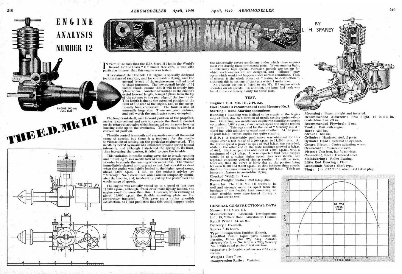
 Sparey found a peak output of 0.128 BHP @ 7,800 rpm. He had not unreasonably been expecting the peak to be found at a somewhat higher speed, but repeated checks apparently confirmed his findings. He commented favorably that the peak of the engine’s power curve was comparatively flat, with an output in excess of 0.12 BHP being developed at all speeds between 6,100 rpm and 9,300 rpm. This showed good operational flexibility. Still, the peak represented only a modest advance over the figures of 0.109 BHP @ 7,000 rpm which Sparey had previously measured for the 2 cc sideport Comp Special.
 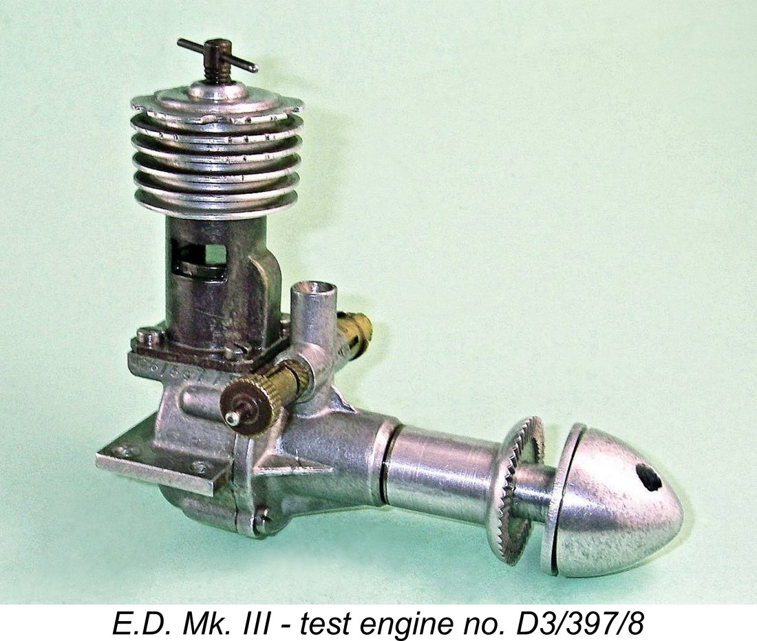 Since I already had a pretty good idea of the levels of performance available from the standard unit, I decided that for the purpose of this review more would be learned by conducting my own test using my very “experienced” engine no. D3/397/8. This unit has lost its tank, having seen a good deal of use in control-line sevice, including some in my hands. However, it remains in first-class mechanical condition, well freed up with excellent compression and good conrod bearings. It is based on an early case dating from April 1948 but has been fitted both with the cut-away cooling jacket and the large-diameter plain bearing front housing.
  With these modifications aboard, the engine performed very well indeed in the air. An 8x8 prop suited it perfectly in control line service. However, I never got around to actually running a test on the modified engine. Time to set that straight!
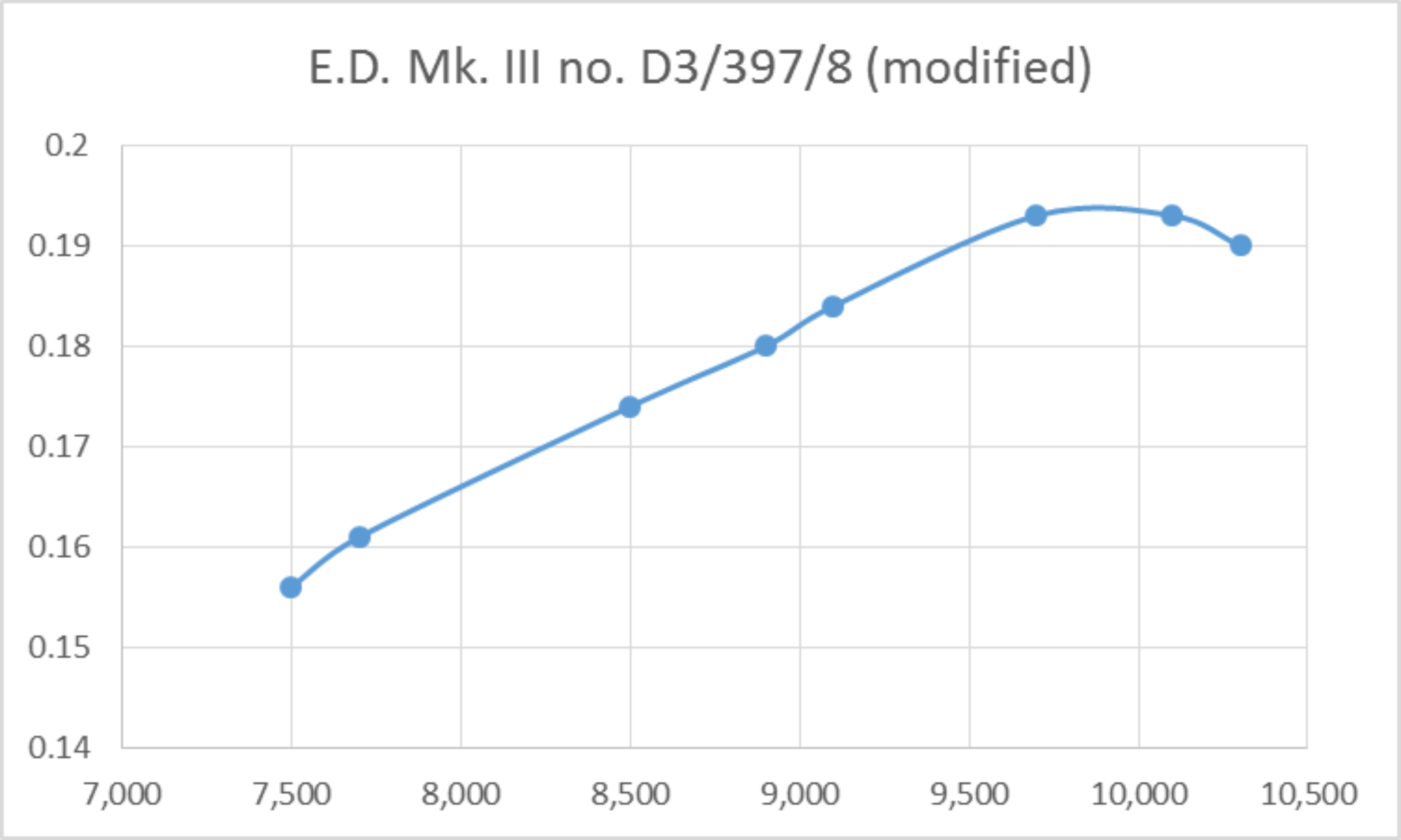
 coupled with the guillotine effect of the piston skirt in impeding gas access to the lower bypass during the transfer phase were clearly imposing severe limitations on the stock engine's ability to reach its potential. The fact that the stock unit with its heavy piston, long stroke and un-counterbalanced shaft was a chronic vibration-producer at the higher speeds would not have helped matters either.
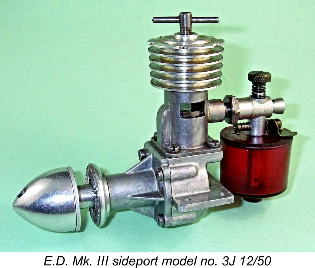
 each prop was to run rich for 1½ minutes and then briefly lean out to find the maximum speed for that prop. I then stopped the engine in full cry using the cut-out, allowing complete cooling before changing props. In this way, the break-in process was continued. Those full-range heat cycles are all-important - probably even more so than the actual running time!
 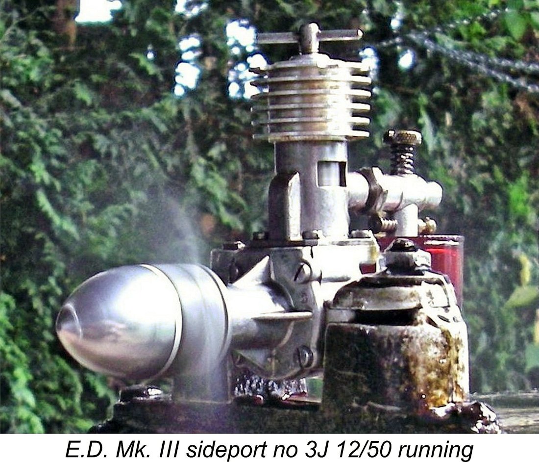 The Mk. III sideporter proved to be almost absurdly easy to start. After the initial run to clear out the storage oil, it never needed a prime - a couple of choked turns to get some fuel into the case were all the preparation that was required. It also proved to be very responsive to both controls, hence being extremely easy to set. Running qualities were excellent - very smooth with relatively minimal vibration. The fact that this variant uses the heavily counterbalanced Comp Special shaft doubtless has much to do with that. Both controls held their settings perfectly at all times.
 The engine seems to have peaked at around 7,700 rpm, at which speed it was developing some 0.117 BHP. This performance doesn't quite match that of my best unmodified 2 cc Comp Special, which delivered around 0.124 BHP @ 8,000 rpm. However, it is well within range of the performance of a standard unmodified example of the FRV Mk. III as determined by both Lawrence Sparey and myself. It must also be remembered that my sideport Mk. III remains quite stiff, clearly requiring considerably more running-in time to give its best, while my tested Comp Special is an old hand! I could see the sideport Mk. III doing measurably better than this if it was well freed up.
 My own tests reported above have shown quite conclusively that with a little more attention to some very obvious design shortcomings, the engine could have been one of the early pace-setters in the 2.5 cc diesel field. The problem of the piston skirt obscuring the bypass entry at bottom dead centre was an obvious and easily remedied design flaw. In addition, the fact that the engine used FRV induction with a relatively early closure after top dead centre allowed far more effective use of the sub-piston induction principle. Finally, a little counterbalancing of the crankweb would have done wonders in terms of reducing the long-stroke engine's tendency to vibrate.
 | |