
|
|
Towards the Miniscule - the Early Diesel Miniatures
The creation of functional model internal combustion engines at minimal sizes has always posed an almost irresistible challenge to model engine designers and constructors, who have shown themselves to be endlessly curious to discover just how small a model internal combustion engine can be built and still operate successfully. The rest of us less talented individuals have cheered from the sidelines and sometimes supported these designers through our purchases of their commercial products. In the past thirty years or so, an amazing variety of tiny sub-miniature model diesels has emerged from the workshops of talented makers from China to Russia and all points in between. We tend to take such miniatures for granted, knowing that numerous previous examples have demonstrated the practicality of making diesels down to very small displacements. I suppose that the novelty has worn off to some extent .............. However, it was not always so. Even before the advent of the model diesel allowed modellers to dispense with the heavy, bulky and undependable ignition support systems required by spark ignition engines, the question of just how small a working internal combustion engine could be made seemed to call for an answer. Because the minimum weight of the required ignition support system was essentially unaffected by reductions in engine displacement, considerations of overall power-to-weight ratio led to the .099 cuin. (1.63 cc) displacement The most remarkable of these individuals was undoubtedly the great American model engineer Ray Arden, who made a total mockery of accepted displacement limitations by constructing and demonstrating a successful operating spark ignition motor having a displacement of only 0.025 cc!! Bore and stroke were 0.125 in. (3.2 mm) apiece. Having no alternative, Ray made the near-microscopic spark plug himself. One can only stand in awe……………a talent like that doesn’t surface very often! However, it was the advent of the model compression ignition engine (aka “diesel”, an incorrect term with which we’re stuck!) that really turned the attention of model engine designers towards the concept of producing practical sub-miniature powerplants. It might be supposed that the intent was to open up a new field in aeromodelling, but the underlying concept actually seems to have been the simple replacement of rubber motors and their progressively-declining outputs during flight with a small I/C engine with its steady and controllable output during the easily-timed run. Such engines were initially seen primarily as replacements for rubber power in the same types of model. This was a perfectly valid basis upon which to embark upon the development of sub-miniature I/C engines. However, plain old curiosity doubtless played a significant role as well. Once the concept presented itself, it didn’t take long for skilled model engineers in a number of countries to begin to explore the practical lower displacement limits for model diesels. Here I’ll look at some of the early attempts to produce sub-miniature diesel engines, grouping them for the most part under the name(s) of their creator(s). Purely for the purposes of this article, I’ll define “sub-miniature” as anything below 0.021 cuin. (0.35 cc). This is a completely arbitrary limit, but I have to draw a line somewhere in order to maintain my focus on the really little ’uns - this limit excludes the numerous diesels of around 0.4 - 0.6 cc displacement which are certainly pretty small but don’t really qualify as true sub-miniatures in my book. As far as the period to be covered is concerned, I’ve once again made a somewhat arbitrary decision by limiting the present discussion to engines developed up to and including 1960. I’m very well aware that this excludes a lot of really impressive sub-miniatures which have appeared in later years, but again I have to draw the line somewhere in order to hold the article down to a reasonable length. The post-1960 engines may form a suitable subject for a future article to complement this one - we’ll see…………. Finally, in this article I have refrained from including full technical details of the engines concerned. Instead, I’ve provided links to more comprehensive articles and test reports (where these exist) to which readers can refer for more information. To do otherwise would make the present text unmanageably long. With the above boundaries having been established, let’s get down to it! Early Examples In this section of the article, I’ll deal with the various individuals of whom I’m aware who created successful sub-miniature diesels during the early post-WW2 period when such creations represented forays into previously uncharted territory. I’ll cover these creations more or less in the order in which they appeared. In this way I hope to build up a chronological picture of pioneering efforts to explore the lower limits of potential displacements for model diesels. We’ll begin with a necessarily very brief visit to Italy. Early Italian Micro-Diesels My good mate Maris Dislers has drawn my attention to a couple of very small diesels produced in Italy during the period covered by this article. The existence of these engines is known thanks to their inclusion in the tables to be found on the very informative Italian Engines online database. These Italian micro-diesels are grouped together here becauise there's insufficient information on them to justify individual entries. They appear together as the first entry in the present article because one of them, Elios Vantini's "Antares" 0.15 cc diesel from Padua, appears to have been the very first micro-diesel of them all, having been made in 1943. As such, it was a historically significant technical achievement in the context of the present study. However, because it was made while WW2 was still ongoing, the little engine escaped any attention from the modelling community. Vantini is far better known for the larger-displacement "Antares" models, notably his 4 cc design. The 0.15 cc miniature seems to have been no more than an experiment. The website entry for this unit tells us that it weighed 17 gm and that only one example was made. No other details are available. While we're looking at developments in Italy, we may as well take note of another Italian micro-diesel of the period which appears in the Italian Engines database. This is the Borancin 0.17 cc diesel made in Verbania. Beyond its displacement plus the fact that it was made in 1947, no details whatsoever are available. We are not told how many examples were made, nor is it clear whether or not the engine entered series production at any level. If any Italian reader is able to provide more details, I'd be happy to add them to this article. Having said as much as I'm presently able to say about these two Italian miniatures, I can now begin to look at a series of early micro-diesels about which far more is known. We'll continue our journey in Paris, France. Prosper Allouchéry - France
A few examples of this superb little motor were produced to very high standards by Prosper Allouchéry of Paris, France in 1946, attracting considerable attention. This was almost certainly the idea - Allouchéry never seems to have so much as considered putting this little gem into series production. He engaged in the commercial manufacture of a range of very well-made model engines under his own name, but the 0.16 cc model was never one of his commercial offerings. Instead, these little engines were individually constructed in miniscule numbers as a non-commercial “manufacturer’s trade show statement”. Allouchéry demonstrated them at trade shows to attract attention to his larger-displacement commercial offerings, but only a very few examples were ever made as required for demonstration purposes and perhaps as keepsakes for friends and trade associates. Good luck trying to find one today!! The Allouchéry Éclair was a noteworthy achievement on its own merits. It was widely touted as the world’s smallest-displacement functional model diesel at the time. In reality however, as of late 1946 that honour almost certainly belonged to the remarkable miniature diesels constructed by the Swedish model engineer Harry Fjellström. Harry Fjellström - Sweden
Harry’s first effort in that direction was a reduced-scale rendition of the Rogstadius design, which was itself in essence a Dyno clone. Bore and stroke of this little creation were 6 mm and 9 mm respectively for a displacement of 0.254 cc. This engine attracted considerable attention at the time, being featured in both “Flyg” and "Populär Teknik" magazines in May 1946. It was referred to as Sweden’s smallest model engine, which it almost certainly was when it appeared. However, there was much more (or should I say much less) to come! Encouraged by the success of his little 0.254 cc diesel, Harry became convinced that the lower limit of displacement still awaited discovery. His next move was to build a further downsized version of his established Rogstadius-based design, this time having a bore of 4.1 mm and a stroke of 6.2 mm for a displacement of 0.082 cc and weighing only 15 gm. This engine too was a resounding success, running very well.
Harry was always happy to demonstrate his little mechanical marvels, and this one caused quite a stir when it first appeared - people could scarcely believe it! The engine even attracted interest from outside the modelling world - the full-scale boating publication "Till Rors" ran a feature on it which included the comment that when first started it sounded like a fly and when fully opened out it sounded like a mosquito! The engine was also featured in the December 1946 issue of "Populär Teknik" magazine. As a result of all this publicity, Harry's efforts did not by any means go unnoticed in his native Sweden. Being fortunate enough to be living in an enlightened country in which the creative work of talented individuals such as himself was highly valued for its own sake, in November 1946 he received an award from the hand of the Minister of Education for his remarkable engines. I can only agree that this award was very well deserved!
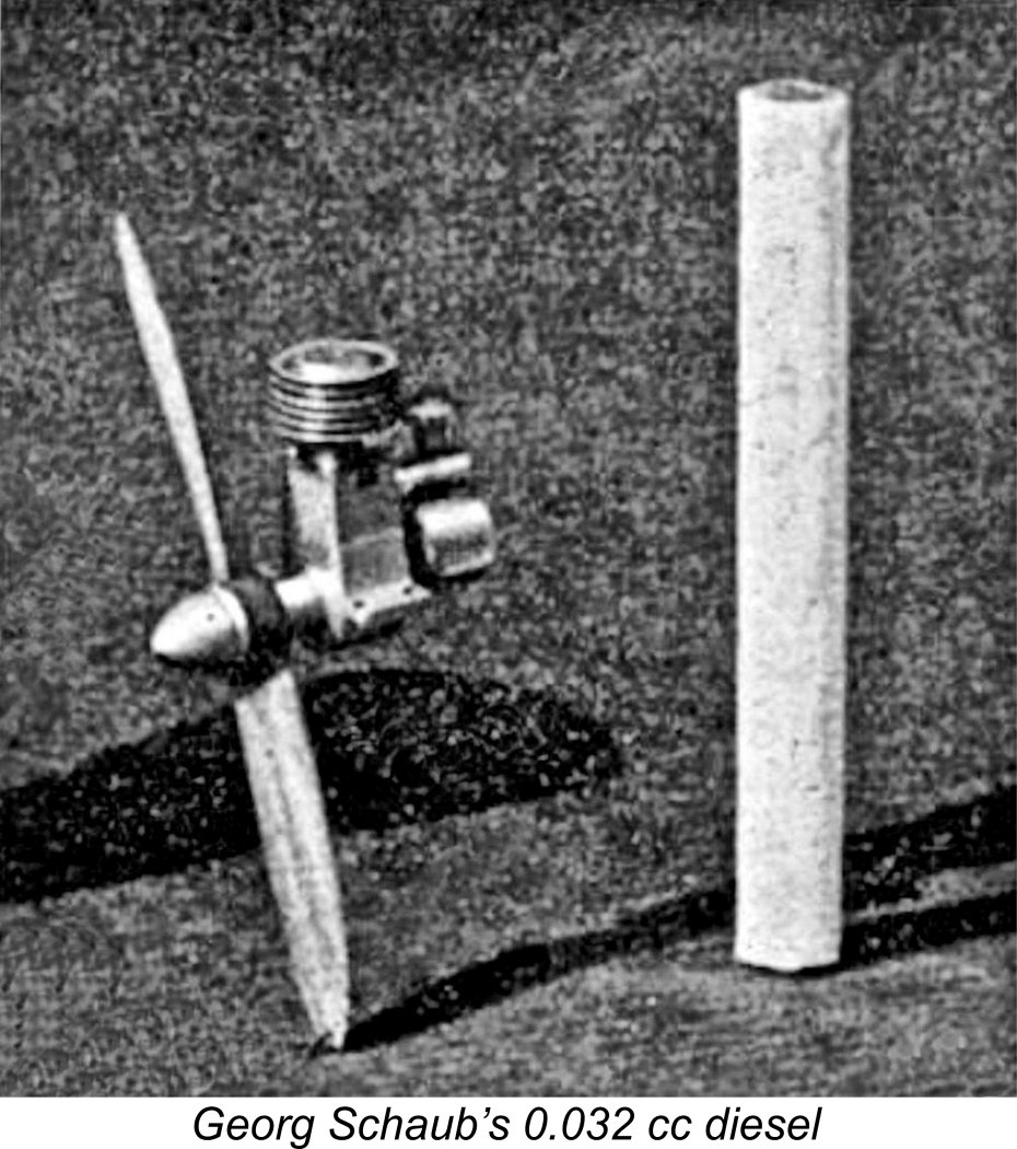
Harry had attended the 1947 “Model Engineer” exhibition in London, England as a steward. In 1948 he returned as an entrant. By this time his little diesel had done so much running at demonstrations that it had required a rebore, increasing its displacement to 0.044 cc. Harry entered this engine plus his 0.082 cc model and a beautiful miniature "tear-drop" tether car that he had built for one of his 0.254 cc powerplants. After the Exhibition, he received a letter of thanks from the Exhibition Manager E. D. Stogdon. He kept that letter for the rest of his life. Mention of Harry’s 0.254 cc tether car at the 1948 exhibition brings up the fact that from 1947 onwards Harry had turned his attention to tether car racing, then very popular in Sweden. He continued to participate in this branch of the modelling hobby until early 1950, after which he evidently moved on to other interests. During his 5 year involvement with model engineering he had created a legacy of superbly-crafted engines, cars and car components which survive today in the form of the Harry Fjellström collection at the Tekniska Museet (Technical Museum) in Stockholm, where they may be examined by appointment. Georg Schaub - Germany? Harry Fjellström seems to have stirred the competitive juices of a number of skilled model engineers who decided to see if they could further lower the displacement mark that he had set. Among these individuals was a certain Georg Schaub. We only know about his effort because of the publication of a short illustrated Unfortunately, neither the publication in which this article appeared nor its date are presently known. The design of the illustrated engines suggests a late 1940's or early 1950's date, but we can't be certain. We don't even know Georg Schaub's nationality, although he was almost certainly a citizen of Germany or some other German-speaking country. The article tells us that he was a quite well-known and experienced precision engineer who specialized in small engines. His little micro-diesel was by no means his only creation - the article included an illustration of a 2.5 cc car unit which he had constructed. Schaub's little micro-mastepiece was a basically conventional sideport diesel of the late 1940's or early 1950's. The fuel tank style in particular has a definite 1940's look to it. According to the specifications included with the article, the engine had a displacement of only 0.032 cc, thus setting a new record for diesel displacement miniaturization. The bore was given as 3 mm (less than 1/8 in.!), which would make the stroke 4.5 The article commented upon the fact that the construction of an engine at this size required the use of magnification along with watch-maker's equipment. The writer noted that while the practicality of such a tiny engine in a modelling context was open to debate, it had great value from a technical standpoint in demonstrating the applicability of compression ignition at truly miniscule sizes. According to the article, the engine was a bit of a challenge to start - no surprise there! In addition, the ideal fuel for such a tiny motor was still open to further experimentation. However, once running, the little motor reportedly turned its custom-made aluminium alloy airscrew at 12,000 rpm, sounding like an angrily-humming insect in doing so! The writer reported an output of 0.028 BHP, but this was undoubtedly in error since it implied a specific output of over 870 BHP/litre! It's pretty clear that the publishers dropped a decimal place here and that the true claimed output was 0.0028 BHP. Even that figure was quite impressive given the engine's displacement. One wonders how Schaub actually measured any output figure at all ............ Overall, a remarkable achievement by a model engineer of unusual ability. I only wish we knew more about him! Can any reader provide more information? H. H. Groves - England
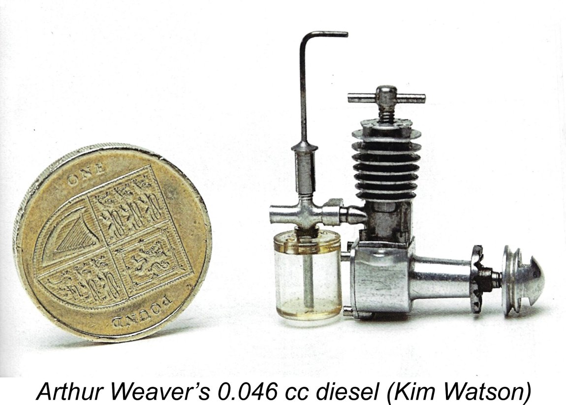
Groves worked in a variety of positions relating to instrument making and tool making before retiring in 1937 at the early age of 55. His earlier model engineering interests focused on live steam engines and flash steam hydroplanes, but after WW2 he began to take an interest in model diesels, perhaps encouraged by Lawrence H. Sparey, who seems to have been a personal friend. In 1946 at the age of 64 years, Groves decided to attempt the construction of a tiny model diesel designed as a 1/3 linear scale variant of Sparey's well-known 5 cc unit. An article by Groves describing the construction of Regardless, the finished engine weighed a mere 0.707 ounces (20.04 gm). It reportedly turned a 5½ x 2½ airscrew (which Groves considered to be oversized) at 4,800 rpm. Groves installed it in a 25½ in. span Leopard Moth weighing 4 ounces. He subsequently constructed a slightly larger version of the same design at half linear size having a displacement of 0.625 cc and weighing 1.875 ounces (53 gm). Groves died of heart failure in January 1965 at age 82 following a bout with pneumonia. Arthur Weaver - England Harry Fjellström’s influence evidently extended to areas well beyond Continental Europe. I've already mentioned his visit to England to participate in the 1948 "Model Engineer" exhibition, at which he demonstrated both his 0.082 cc and 0.044 cc models, attracting considerable attention in doing so. Although acting as a steward as opposed to an entrant in 1947, it would be more than a little surprising if he hadn't demonstrated his little creations on that occasion also - they were certainly in existence as of that year. Among those who took notice of Fjellström’s miniatures was the well-known British model engineer Arthur F. Weaver (1904 - 1973), then resident in Hendon, a little to the north-west of London. Weaver was one of a significant number of enthusiasts who embraced both tethered hydroplane and rail-guided car racing during the heyday of those sports in the 1940’s and early 1950’s. Many of the participants in those activities were superb model engineers in their own right, and Arthur Weaver was certainly among their number.
Arthur Weaver continued in the model engineering field for some years then to come, including a stint working with Dennis Allen and Len Steward at Alperton producing the latter-day AMCO 3.5 cc models. He is perhaps best known for his excellent 1 cc sideport diesel which was expressly designed for home construction. A summary of Weaver's life and work together with a review of his 1 cc diesel may be found elsewhere on this website. That article includes a link to the plans for that engine. R. Trevithick - England
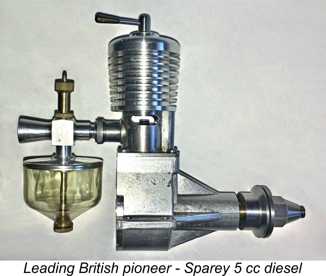
This situation changed very quickly following the conclusion of the conflict, the main catalyst being the December 1945 publication in “Aeromodeller” magazine of a ground-breaking article by Lawrence H. Sparey entitled “The Gen on “Diesel” Engines”. Sparey had already constructed a number of successful working diesels, albeit of more conventional displacements. His 5 cc diesel design was published in the magazine to assist home constructors. It ran well enough but was a bit of a bone-shaker! A very large number of examples of this very influential design have since been constructed, going right up to the present day. In his article, Sparey set out the basic principles underlying the construction and operation of model compression ignition engines. This was followed up in March 1946 by an article in the same magazine by Squadron Leader Peter Hunt on the subject of model diesel fuels. Armed with these comments, it didn’t take very long for British model engine designers to get to work on the development of model diesels suitable for commercial production. The first of these was evidently the Dyno-based Leesil 2.5 cc model from Bradford in Yorkshire, which was soon followed by the Mills 1.3 and Owat 5 cc models. The diesel was well launched upon the period of some 20 years or more during which it was to dominate the British power modelling scene.
Working to very high standards, Trevithick hand-crafted a small series of beautifully-made one-off model diesels having very small displacements. Two of these engines were included in the first edition of Col. C. E. Bowden’s late 1947 book “Diesel Model Engines”, from which the attached illustration is taken. Both were sideport diesels of relatively conventional design arrangement. The first engine had bore and stroke dimensions of 0.250 in. (6.35 mm) and 0.3125 in. (7.94 mm) respectively for a displacement of 0.251 cc, while the second used the same bore with a slightly longer stroke of 0.3437 in. (8.73 mm) for a displacement of 0.276 cc. Trevithick went on to make a number of engines of larger displacement, including a 0.9 cc sideport model and a front rotary valve (FVR) 2.5 cc diesel of relatively advanced design. Both of Trevithick’s sub-miniatures reportedly ran very well, thus demonstrating the practicality of the construction of such small engines to all British model engine designers. It was inevitable that some British commercial model engine producer would sit up and take notice. That honour fell to Harold Kemp of Gravesend in Kent, England. There were other individual British model engineers who tackled the challenging task of producing a practical sub-miniature model diesel. Among these were A.A. Sherwood, a professional electrical engineer who exhibited a tiny hydroplane powered by his own 0.3 cc diesel at the 1947 "Model Engineer" exhibition. Sherwood also published under the pseudonym "E.R.E.", subsequently relocating to Australia. He became best known for his amazing live steam locomotive miniatures, all the way down to HO scale. There was also A.G. Boulting, who published a design for a 0.3 cc diesel in the October 20th, 1949 issue of "Model Engineer". I'm sure that there were others, but it's now time to move on into the realm of commercial sub-miniature diesel manufacture. The Early Commercial Productions So far, none of the really small diesels which had appeared from various designers had reached the stage of commercial exploitation. A few pioneering designs such as the Ace 0.5 cc and (later) the Comet 0.4 cc models had appeared in England as commercial productions, pointing the way towards commercial exploitation of the lesser displacements. However, it was left to Harold Kemp of Gravesend in Kent to initiate the commercial manufacture of engines in what I consider to be the true micro-diesel category. Harold Kemp - England After working in the aircraft industry for Short Brothers of Rochester, Kent during the WW2 years, Harry Kemp had established himself in late 1946 in nearby Gravesend as a model engine manufacturer, albeit on a relatively small scale. His first model diesel, the 4.4 cc K4, appeared in early 1947 and was followed fairly quickly by a 1 cc model. Both of these engines have been reviewed in detail elsewhere on this website.
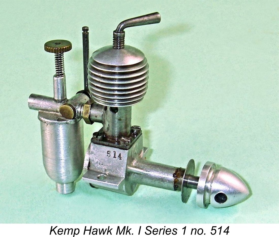
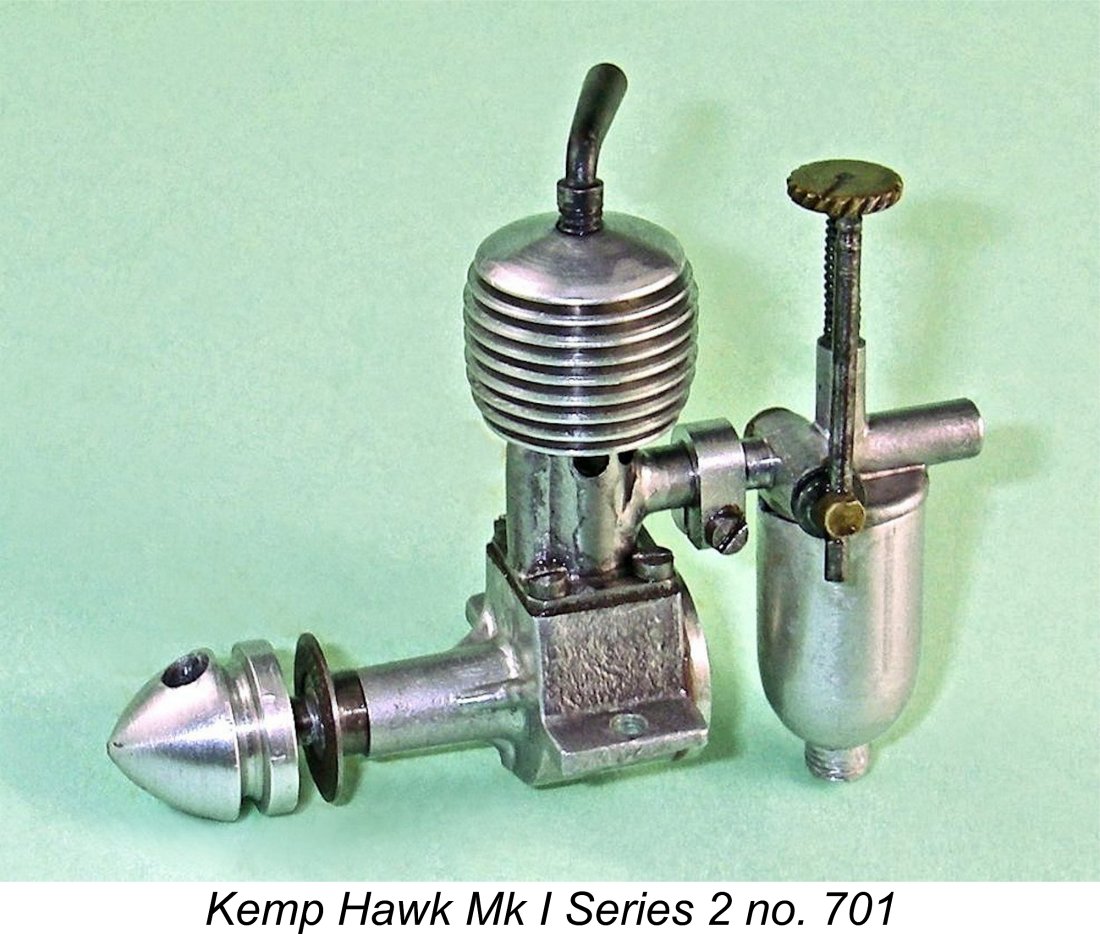
Taking note of the fact that he would have no commercial competition in this field at the outset, Kemp set about designing a simple sideport diesel of only 0.2 cc nominal displacement which could be manufactured in commercial quantities at a reasonable profit. The result was the first model of the soon-to-be-famous Kemp Hawk. This cute little long-stroke sideport diesel featured nominal bore and stroke dimensions of 0.219 in. (5.56 mm) and 0.3125 in. (7.94 mm) for an actual displacement of 0.193 cc (0.012 cuin.). This was It seems that the intention had been to release the little Hawk in time for Christmas 1947. However, the fact that the engine doesn’t feature in any hobby shop or distributor listings for December 1947 suggests that this goal was not achieved. The Hawk actually appears to have made its debut in January 1948, selling very well from the outset at a price of £4 8s 0d (£4.40). The Series 1 version of the Mk. I Hawk used an internal bypass flute which was formed in the interior wall of the cylinder at the front. This bypass was supplied at its lower end through a port cut through the piston wall above the gudgeon pin at the front. The piston interior thus served as part of the bypass passage. The downside was the fact that the depth of the piston wall above the piston port was relatively short, thus presenting a much reduced gas leakage pathway past the piston at that point. The design would likely be relatively intolerant of any wear in the piston/cylinder fit. The 0.193 cc Mk. I Series 1 version of the Kemp Hawk was never the subject of a published test in the contemporary modelling media. My own testing of an un-numbered but mechanically perfect example of this type in my possession yielded the following figures.
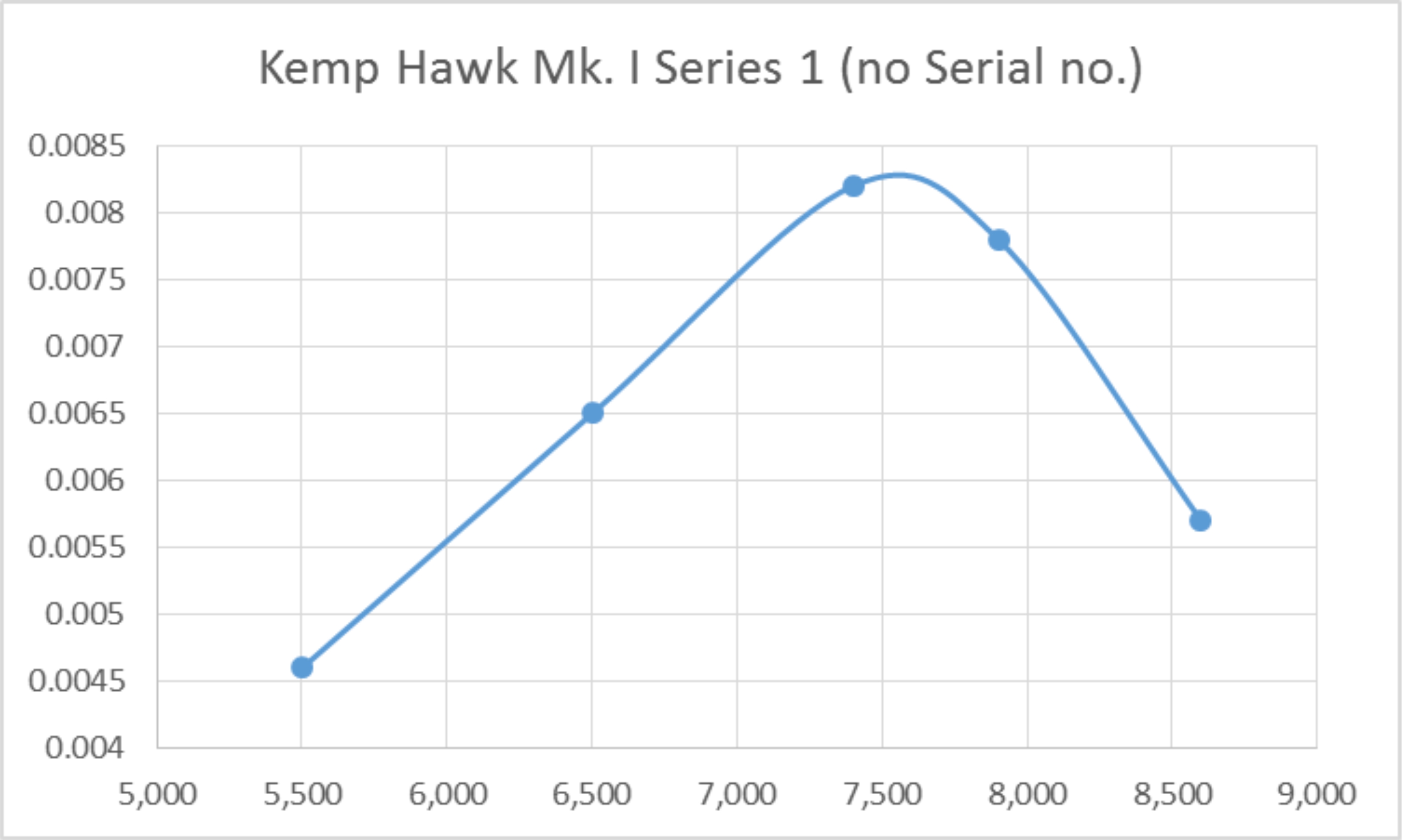
The engine proved to be an extremely good starter, to the point where it was easy to forget how small it actually is! Control response too was excellent, allowing the best speeds on each prop to be established very dependably. Running qualities were beyond reproach, while the cut-out worked perfectly, greatly facilitating the testing - Lawrence Sparey, who had endless trouble with cut-outs, would have loved this one! The engine evidently developed some 0.0083 BHP @ 7,600 rpm - not a totally dismal performance for an early 1948 engine of this type and displacement.
A strengthened case with three stiffening webs on the main bearing had already appeared on some of the later Series 1 models, and now a few substantial changes were made to the cylinder. The most important of these was an increase in the bore to 0.250 in. (6.35 mm), the stroke remaining unchanged at 0.3125 in. (7.94 mm). This resulted in an increase in the engine’s displacement to 0.251 cc - a 20% increase. The new model is generally designated as the Kemp Hawk Mk. I Series 2. The bore increase forced a change in the bypass arrangements, since there was no longer sufficient cylinder wall thickness to accommodate the internal bypass flute used formerly. The engine now featured lower bypass and upper transfer ports cut through the lower and upper cylinder wall respectively. These ports were externally connected by a soldered-on bypass channel attached to the outer cylinder wall at the front, exactly like the system used on the contemporary E.D. 2 cc sideport models. The mode of attachment of the fuel supply system was also changed from a screw-in arrangement with a lock-nut to a split socket which was tensioned by a tiny clamp to secure the plug-in delivery end of the venturi tube. The piston port used in the Series 1 model was no longer required, accordingly being omitted. As we might expect, these changes resulted in a very substantial increase in the engine’s torque development. If the motivation for the changes was an improvement in output, they certainly succeeded! Testing of my own illustrated example, engine no. 701, yielded the following data.
The above data confirms that the modified Hawk with its 20% greater displacement and far more efficient bypass stands head and shoulders above its Series 1 predecessor. It started just as readily as its smaller forebear and was just as easy to set. Running qualities once again left nothing to be desired. This particular example of the little Hawk delivered an outstanding performance, developing some 0.018 BHP @ 10,000 rpm. I have to say that this was well above my expectations. It's possible that this is a better-than-average example. In mid 1948, Kemp Engines was taken over by Len Steward, who continued the business under the name of the "K" Model Engineering Co., still located at Gravesend albeit in different premises. At this point, Steward became responsible for the next moves in the Hawk saga. Len Steward - England
This final variant of the sideport Hawk was the subject of a retrospective mini-test which appeared in the August 1954 issue of “Aeromodeller” to provide a comparison with the then newly introduced Allbon Bambi, of which more below in its place. The tester reported a peak output of 0.0073 BHP @ 9,000 rpm. This of course is well below the performances extracted from my own Series 1 and Series 2 examples - I have no explanation for the difference. All I can say is that I'd be glad to duplicate my results for any interested party who should happen by! Production of the sideport Hawk seems to have ended by early 1949. During the approximately one-year production life of this little unit, serial numbers suggest that the two companies involved produced some 1900 examples of all Series combined.
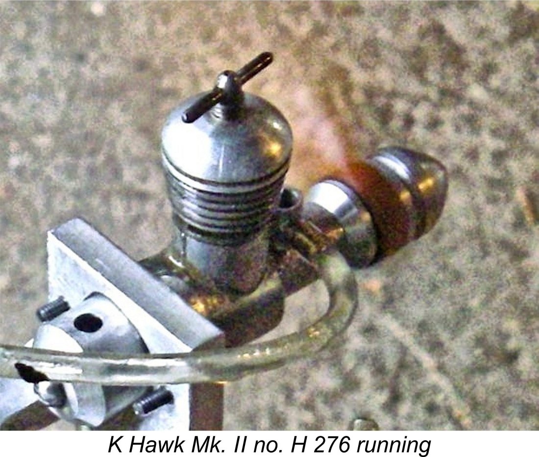
Quite apart from the above sweeping changes, bore and stroke were drastically revised. The designer clearly expected peak output to be achieved at a higher operating speed. In addition, the new model’s theoretically greater efficiency would allow its displacement to be reduced somewhat while still maintaining an adequate output. For all of these reasons, the new version of the Hawk featured “square” internal geometry, with bore and stroke both being set at 0.250 in. (6.35 mm). The resulting displacement of 0.201 cc put the engine back to very near the figure at which the original Hawk Mk. I had started out. The revised model weighed 31 gm (1.093 ounces) as illustrated complete with tank and fuel tubing. The 0.2 cc Hawk Mk. II was (and is) a delightful little engine to handle, starting and running extremely well. Like all really small engines, it is somewhat sensitive to the amount of fuel present during starting, but once going it is very responsive to both controls, albeit being a bit touchy regarding the precise needle setting for best running. Once again, this is a typical characteristic of very small diesels. The engine also displays a preference for having the needle opened a little from the running position when starting from cold. My test example of the Hawk Mk. II, engine no. H 276, was formerly owned by my late long-standing Canadian friend Squadron Leader Laurie Ellis, RCAF (in his day, a frequently-published model designer - anyone else remember the Vultan, Javelan and Contra-Gyro?). Laurie had bought the engine new in 1949 and had put it to considerable use in small free flight models. Despite this previous use, the engine remains in excellent condition. My own tests on this example have produced the following data.
As can be seen, the Hawk Mk. II more or less matched the output of its Mk. I Series 1 sideport predecessor of similar displacement, albeit at a slightly higher speed. It was no match at all for the 20% larger-displacement Mk. I Series 2 variant. I suspect that my tested example of the latter model is an exceptional unit.
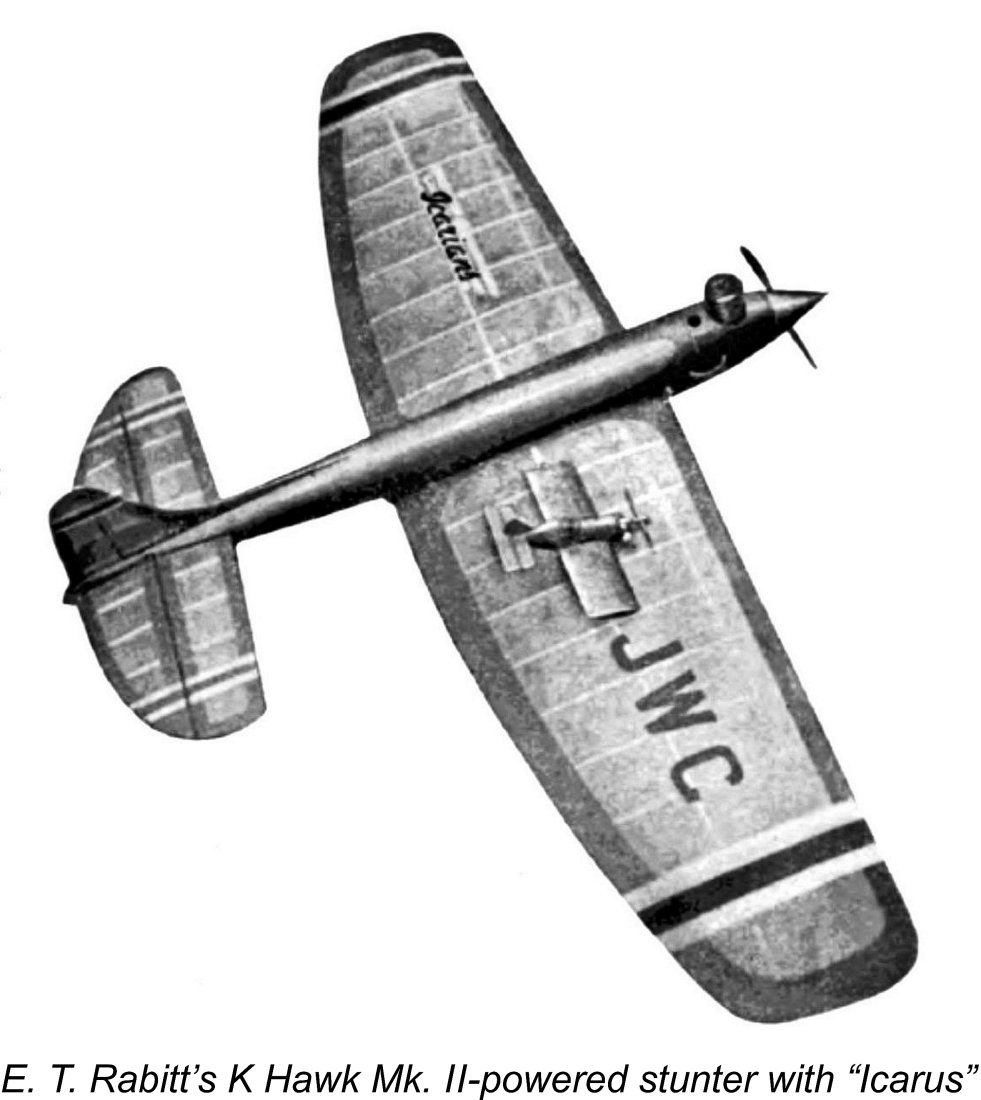
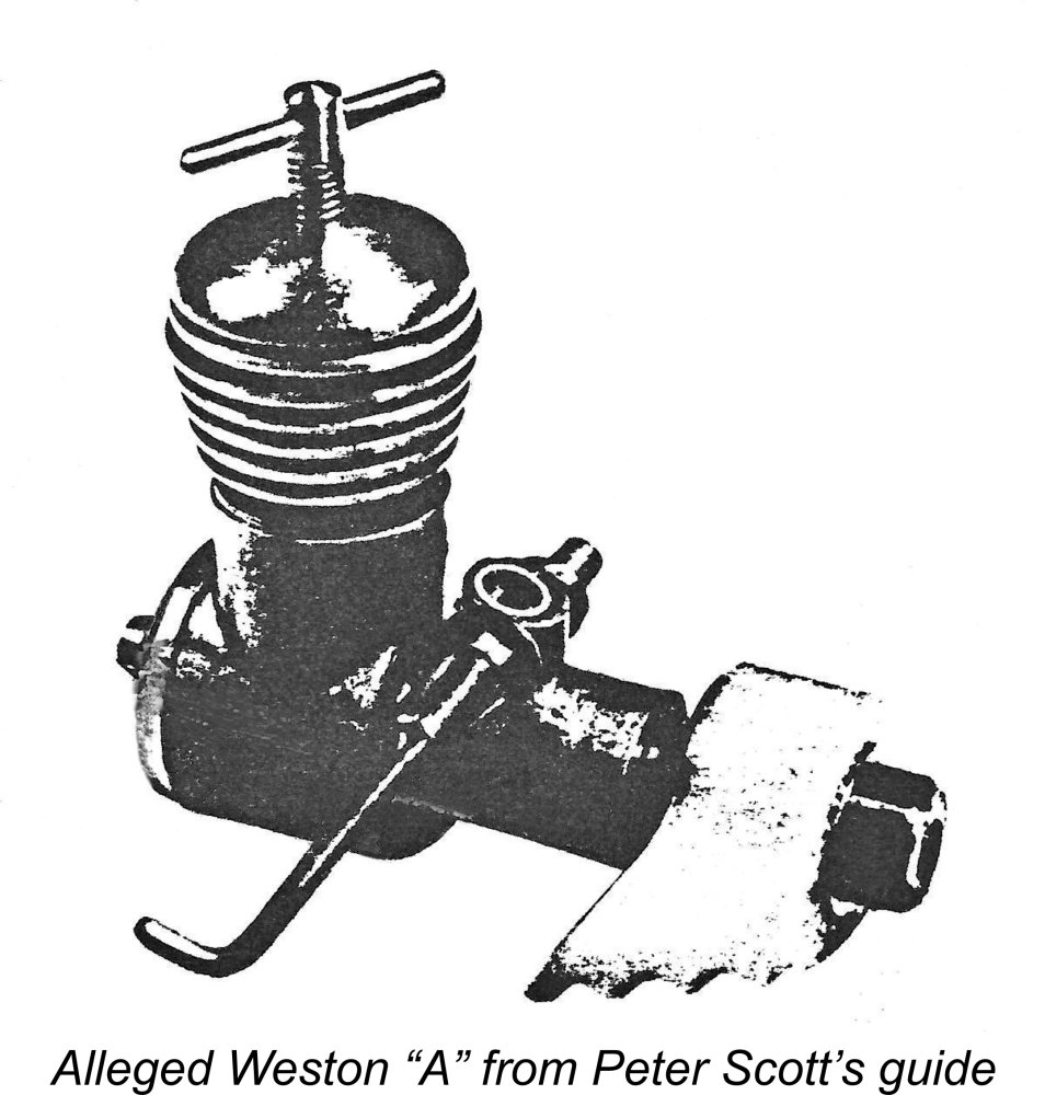
The Hawk Mk. II was the first sub-miniature diesel to demonstrate the capability of flying an aerobatic control-line model. Many years ago now I made a small ultra-light profile control-line model for one of these engines (no. H 276, as it happens). The model flew just fine in calm air on 20 foot thread lines and would actually manage a loop! In this endeavour I was in fact preceded by an otherwise-unknown modeller named E. T. Rabitt, who designed and built a tiny 10 in. span cabin stunter for a Kemp Hawk Mk. II. This model came to the attention of a well-known British pioneer stunt flyer named John W. Coasby, who worked as a draftsman for “Aeromodeller” magazine beginning in the late Despite its very worthy qualities, the Hawk Mk. II didn’t survive long on the market. Probably the fact that it really offered no performance advantage over the sideport Hawk models had a lot to do with that. A Series 2 “Special” version of this model was announced, but the absence of any known examples seems to suggest that it never made it past the pre-release advertising stage. By August of 1949, the engine appears to have been withdrawn from production after the completion of at most some 500 examples. So ended the first attempt by a British manufacturer to cater to the market for very small internal combustion engines. Despite the engine's commercial failure, it remains my personal opinion that the Hawk Mk. II was one of the best miniatures to appear during the period now under discussion. However, the Hawk was by no means the last such effort! While Harry Kemp and Len Steward were developing the Hawk in Kent, another sub-miniature design was brewing down in Somerset……. Bill Evans - England Our next example, the Weston “A”, more or less falls into the “legendary” category since, although it undoubtedly existed, I’m not presently aware of any authenticated surviving examples! Neither Mike Clanford nor Ted Sladden managed to find an example to illustrate in their respective books, and between them they Unfortunately, Warring did not supply any structural details or working dimensions - he only confirmed that the engine was no longer in production as of his publication date. It seems likely that he never had a chance to examine one of these units in the metal. The attached image of an engine identified as a Weston "A" appeared in a long-forgotten privately-published illustrated guide prepared in 1975 by well-known English collector Peter Scott in connection with his short-lived “International Aero Engine Collector’s Society” (I.A.E.C.S). I was once a member of this Society, hence still having a copy of the guide, from which this image was extracted. However, I have to say that the identification of the illustrated engine as a Weston "A" seems to me to be open to question. The proportions of the engine seem to suggest a somewhat larger displacement, although the thickness of the prop hub in the image does certainly suggest a small size. To add to the uncertainty, the radial cylinder porting and FRV induction appear to imply a later date than early 1948. I would have considered it to be more likely than not that the Weston "A" was a sideport model. Of course I could very easily be wrong! Radial porting was around at that time, as was FRV induction - a forward-thinking designer in early 1948 could certainly have combined the two. Moreover, Peter Scott would undoubtedly have had a very persuasive basis for identifying the engine as a Weston "A" when preparing his guide back in 1975. However, he can no longer locate the evidence after the passage of 45 years. Can any reader resolve this question? If this engine isn't a Weston "A", what is it? What is quite certain is that the Weston engines were manufactured beginning in early 1948 by (or more probably for) Weston Model Aero Supplies of 1 Oxford Street in Weston-super-Mare, Somerset, England. This firm was owned by a character named Bill Evans, who was a leading light in the local control line community, focusing his business accordingly. The identity of the actual manufacturer of the Weston engines is unknown - it's highly unlikely that it was Bill Evans.
In summary, we know frustratingly little about the Weston “A”. Both the advertisements and Warring’s book reference agree that the engine had a displacement of 0.25 cc, although neither bore nor stroke dimensions were given. Figures of 0.250 in. (6.35 mm) and 0.3125 in. (7.94 mm) would fit the bill nicely, but they’re no more than an educated guess. Both the advertisements and Warring's tables confirm that the Weston "A" weighed 1¼ ounces (35.4 gm). It seems to have first appeared in a March 1948 “Aeromodeller” advertisement in which the Weston range of model engines was “announced”, seemingly dating its introduction quite closely. The listed price was £4 10s 0d (£4.50). It continued to be advertised at the same price through August 1948. The implication of all this is that at least a few examples must have been made during the first half of 1948. The little Weston “A” was accompanied by a sideport Weston “B” diesel of 3.5 cc displacement and a 5 cc model of unknown specification called the Weston “C”.
The only Weston engine that Phil ever saw was the 3.5 cc model. It was apparently used in stunt models at the early 1950 meetings. Phil recalled that it performed poorly against the Elfin 1.8 powered models then in vogue. Starting seemed to be quite a problem compared to the Elfins and it did not rev up as well. He never saw a 5 cc model and never even heard of the miniature 0.25 cc version - hardly surprising in a control-line context. The only small engine that Phil recalled at the time was the little Kalper 0.32 cc diesel to be discussed in detail below.
Of course, Bill Evans and Harry Kemp were not alone in having their eyes on the commercial potential of a really small model powerplant. Down in Southwick, Sussex, a supremely talented model engineer named George Seymour was also turning his attention towards the development of another classic British micro-diesel. George Seymour - England
The name Hylda appears to be a gender-neutralized rendition of the name of Seymour's wife Hilda, who was evidently also an engineer given the inclusion of her name on a patent taken out by the company for a spring-loaded die. Hence this was a small family business run on a "cottage industry" basis - Seymour's son may also have been involved. After the war, Seymour relocated to nearby Southwick, where he continued to operate the business.
Seymour was another individual who found himself greatly attracted to the challenge of creating small compression ignition engines. Before 1947 was out he had begun to develop his own designs for such engines. It’s pretty clear that from the outset commercial production was seen as the goal at which to aim.
Interestingly enough, the advertisements attributed this engine to an entity named Foursome Products at the same address as Arthur Mullett’s shop - the name of Seymour, Hylda & Co. was never mentioned in connection with the Foursome. Consequently, the identity of the actual maker is somewhat unclear - it may or may not have been George Seymour, although there seems to be little doubt that he was the designer. There's also little doubt that the engines were not manufactured at Mullett's shop. My illustrated example of the Foursome, no. G 915, came to me once again from my late friend Laurie Ellis, who had bought it new from Arthur Mullett in 1949 and had used it for a while, finding that it vibrated excessively and couldn’t compete in performance terms with the Mills 1.3. I can confirm these impressions based upon my own testing. Most likely for these reasons, the Foursome was evidently produced in very small numbers, hence being a very rare engine today.
The first model of the Kalper .32 was basically very similar to the earlier Foursome 1.2 cc model. Like its Foursome predecessor, it was a very long-stroke engine, having nominal bore and stroke dimensions of 0.250 in. (6.35 mm) and 0.406 in. (10.31 mm) for a design displacement of 0.327 cc (0.020 cuin.) and a stroke/bore ratio of a massive 1.62:1. This is among the highest stroke/bore ratios of my personal experience, being exceeded only by the larger Foursome model from the same source. Seymour evidently liked long strokes!
The original Kalper variant shown above at the left featured a conventional rear-mounted intake venturi, again exactly like the Foursome. Its construction was somewhat simplified, with a screw-in front housing being employed in place of the Foursome’s multiple-screw attachment. However, in most respects it was simply a scaled-down Foursome. Its manufacturers were identified from the outset as Seymour, Hylda & Co. of Southwick, Sussex. A rather classy feature of the Kalper was the plastic disc which was affixed to the front of the crankcase and displayed the maker’s name and location. This original version of the engine was the subject of a test by Lawrence H. Sparey which appeared in the Like the Foursome, the Kalper .32 was initially distributed solely by Arthur Mullett. The engine appears to have become quite popular in fairly short order, to the point that George Seymour was encouraged to develop a revised Mk. II version of the engine. This revised version of the engine appeared in mid 1949. The new variant differed from the original version in having the induction port relocated from the rear of the cylinder to the side, thus avoiding any potential fouling problems with the gudgeon pin. It also featured a most unusual “dog-leg” intake tract which allowed the fuel jet to be concentrically aligned with the upward portion of the intake rather than being oriented transversely in the usual way - the accompanying sectioned view extracted from the published "Model Aircraft" test should make this clear. However, in other respects the design was little changed.
I've run tests on several examples of the Kalper .32 Mk. II in my own possession, finding the little beauty to be a pure delight to run. It starts very easily using conventional methods - you forget just how small an engine it really is. Control response is outstanding - in particular, the very fine thread and shallow taper on the needle valve render the engine completely free from the typical "micro-diesel" sensitivity to the needle setting. The slightly better of the two examples of the Kalper .32 Mk. II in my possession yielded the following data on test.
The above data suggest a peak output for this example of around 0.0171 BHP @ 9,200 rpm. These figures are completely consistent with Chinn's findings, particularly bearing mind that differences in performance between different examples of the same production engine tend to become more exaggerated with decreasing displacements. My tested example has been well used, hence probably being better run-in than Chinn's test engine.
Surviving serial numbers suggest that as many as 1500 examples of both variants combined may have been constructed over a three-year period. The engine was still being advertised in early 1951, although the marketing role had then been taken up by another Brighton firm, South Coast Models of 37 West Street. Production of the Kalper presumably ended in early 1951 following the untimely death of George Seymour at the age of only 67 years after a short illness. A more comprehensive article about George Seymour and his engines will appear on this website in due course. Having just spent quite a bit of time in England, let’s now take a quick look at what was happening on the other side of the Iron Curtain in Russia. S. Bashkin and V. I. Petukhov - Russia In a separate article to be found on this website I’ve taken an in-depth look at Russian model engine developments both before and after WW2, in which conflict Russia was very much involved, sustaining far greater casualties than any other nation. Despite the horrific impact of WW2 and the subsequent repression of the population under the dictatorial government of Josef Stalin, model engine development resumed surprisingly quickly once the war had ended.
Among those who worked at or with CAML during the early post-war period were the well-known free flight specialist and engine designer Vladimir I. Petukhov and another engine designer named S. Bashkin. In 1948 these two individuals seem to have engaged in a friendly contest to see who could build the smallest working model diesel engine.
Encouraged by the success of this little unit, Bashkin proceeded to go even further down the miniaturization road. His next effort was the VNK-5, a tiny sideport diesel of only 0.13 cc displacement. This model dispensed with any cooling fins on the cylinder - the designer clearly considered them to be unnecessary. While this little motor too evidently ran OK, neither of Bashkin’s designs were ever pursued further.
This led to the creation of one of Petukhov’s true masterpieces - the remarkable little “Molecule” diesel (Молекула in Russian) of only 0.045 cc displacement, which more or less matched Fjellström’s achievement. The surviving image confirms that this was a very long-stroke engine. Bore and stroke of this tiny creation are unknown, but figures of around 3.2 mm bore and 5.5 mm stroke would fit the bill nicely. It was certainly an impressive model engineering achievement. However, it was only one of a notable list of accomplishments chalked up by Petukhov during his long and distinguished modelling career. Having briefly visited Moscow by way of a change of scene, let’s now return to England for a look at another “close but no cigar” example of our chosen genre, this time from a familiar source. Arnold Hardinge - England
Between 1946 and 1948, Hardinge developed both 1.3 cc and 0.75 cc versions of the basic Mills sideport diesel design. He also initiated work on a 2.4 cc disc rear rotary valve (RRV) diesel, although Trevor Wooderson appears to have been primarily responsible for that model. At some point during this period, Hardinge also toyed with the idea of producing a Mini-Mills model. His son Mike Harding (who changed the spelling of his family name) confirmed that his father considered adding a fourth model to the range - a real sub-miniature of only 0.20 cc. Two prototype examples of this little gem were reportedly constructed at Woking. Unfortunately, one of these was lost on its first test flight near Woking, as recalled by Mike Harding who was present to watch this unhappy occurrence. The other survived to be illustrated by Mike Clanford in his well-known "A-Z" book. What a pity that this model never became a commercial reality! R. G. Cameron, Scotland Another indivdual who tried his hand at making a really small diesel during the early 1950's was R. G. Cameron of Gatehouse-of-Fleet in Kirkcudbrightshire, Scotland. Cameron was a watchmaker by trade and a model car enthusiast who was clearly a very talented model engineer, as model car enthusiasts tended to be.
Chinn informed his readers that the engine used a rear exhaust with the single transfer port being located at the front. The cylinder was made from quench-hardened tool steel, with a cast iron piston. Interestingly for such a small engine, the gudgeon (wrist) pin was carried in an alloy yoke which threaded into the piston interior. This design meant that the ends of the gudgeon pin could not foul the fore-and-aft transfer and exhaust ports since the pin did not break through the working piston walls. The conrod was made from a piece of case-hardened nickel steel actually cut from a Norton motorcycle conrod! The crankshaft was a composite component built up using a combination of tool steel and nickel steel. It ran in a cast iron bushing inserted into the separate light alloy front cover, which was attached to the crankcase with four tiny screws. The crankcase was carved from solid aluminium alloy barstock, while the separate alloy cooling jacket was shrunk onto the cylinder liner. The alloy head featured a brass insert to accommodate the compression screw thread. Chinn's article on this engine is highly significant in that it points out a commonly-overlooked design parameter applicable to very small engines. This is the fact that structural strength must be increased in proportion to the engine's displacement as the latter figure decreases. A hydraulic lock is still a lock regardless of displacement, and the engine needs to be able to resist the stresses arising from improperly-managed locks or near-locks. Cameron clearly recognized this - for example, his little engine featured what Chinn described as a crankpin of "unusually generous dimensions for such a small engine". As a result of having been built with plenty of strength, the Cameron 0.15 cc diesel weighed in at a fairly healthy 41 gm (1.45 ounces). Chinn closed his remarks on this engine by saying: "If we are eventually to have smaller engines than the currently-available capacities, it is felt that a little more attention on the part of engine manufacturers to strength rather than fractional savings in weight would not come amiss". Wise words .............. Interestingly enought, several photos of the Cameron 0.15 cc diesel later appeared in the December 1957 issue of the Czech modelling magazine "Letecky Modelar" (Aero Modeller). It seems that some kind of cooperative editorial relationship existed between "Model Aircraft" and "Letecky Modelar". Thanks to Maris Dislers for making this connection and also for locating the original 1953 article. Hermann Fricke - Germany
The unit with which we must concern ourselves in this article was actually Fricke's very first engine constructed in 1951 on his watchmaker's lathe. This was a neat little 0.10 cc diesel which utilized rear reed valve induction. It was not constructed as a commercial venture - indeed, the number of examples made is unclear. There may have been only the one - I have no authoritative information on this score. Regardless, if the quality of Fricke's later work is anything to go by, it would have been beautifully made and probably ran very well. Alan Allbon - England By mid 1951 all of the commercial British sub-miniatures described above had been withdrawn or abandoned for one reason or another. Indeed, by that time neither the "K" Model Engineering Co., makers of the Hawk, nor Kalper manufacturers Seymour, Hylda & Co. were still in existence.
Allbon had already designed several very successful diesels in the shape of the 0.55 cc Allbon Dart, the 1 cc Allbon Spitfire and the 1.5 cc Allbon Javelin. All of these models used the same combination of radial cylinder porting allied to crankshaft front rotary valve (FRV) induction. In mid 1953 Allbon turned his attention towards the exploration of the lower displacement limit to which an engine of this arrangement could be commercially constructed. Development work commenced in the second half of 1953, while a “name the new model” contest was run in the pages of “Aeromodeller” magazine starting in November 1953. The winning name of “Bambi” was submitted by an unnamed Norwegian enthusiast and was announced in the January 1954 issue. The production version of the Allbon Bambi seems to have come onto the market in May 1954 following what appears to have been a somewhat troubled gestation period at D-C Ltd. The price at the time of the engine’s release was a rather stiff £5 8s 11d (£5.45), a figure which reflected the additional level of effort required to maintain tolerances as the displacement went down. The company’s cylinder lapping wizard at the time, Arthur Firth, later recalled that the piston/cylinder fit on the Bambi was “a bugger to get right!”.
This still made the Bambi the smallest-displacement engine ever to enter commercial series production, a record which it probably still holds to this day, the Cox TD .010 and the various later limited-production individually constructed models of lesser displacement notwithstanding. The engine weighed 20 gm complete with tank and fuel tubing. Naturally, such a tiny engine attracted the attention of the resident engine testers of the day - people were curious to learn if it was just a gimmick or was actually a useable model powerplant. Both Peter Chinn and Ron Warring of “Model Aircraft” and “Aeromodeller” respectively answered this question very clearly, stating that while it needed a bit of knowing to get the starting technique down pat, once the right approach was mastered and the control settings established it was as easy to start as any other small diesel, also running very well indeed. Latter-day experience bears out this assessment completely. Peter Chinn’s test appeared in June 1954. Unusually, he refrained from publishing a full power curve, confining himself to an estimate of an output of perhaps 0.010 BHP @ 12,000 rpm. Ron Warring went a little further in his August 1954 test, publishing a power curve which reflected a measured output of around 0.0065 BHP @ 12,500 rpm. He used some kind of reaction beam torque measurement system to extract these figures.
Experience shows that the engine does indeed peak at somewhere around 12,000 rpm, at which speed the best flight performance is obtained. As long as it’s propped to stay at or slightly below this speed in the air, the engine has plenty of power to fly a small free flight model like the “Tom Thumb” or KeilKraft “Dandy” (the only kit ever produced for the Bambi) very effectively. Propping it for higher airborne speeds simply squanders its potential. That having been noted for the record, the Bambi's peak output is really of little significance - the main point is that it's a perfectly useable little engine which handles far better than its reputation might suggest and would undoubtedly do a very creditable job of flying a small lightweight free flight model. It's by no means as difficult to start as some people seem to believe - once the needle setting is established, it's actually as easy as any other diesel. It just requires extra care in handling due to the very small size of the working components. A word of warning in the latter context - do not be tempted to try an electric starter on a Bambi (or indeed on any other sub-miniature diesel)! Protection of the tiny working components requires you to constantly check that you're nowhere near a hydraulic lock condition. Only a finger can provide the required continual feedback. One of my acquaintances ignored this advice and ended up with a broken crankshaft - the engine hydraulic-locked and stopped, but the starter and prop didn't! I had another Bambi through my hands which had suffered a broken wrist pin from the same cause. I've also heard of several Ronald Valentine miniatures which have suffered failures due to the use of electric starters. Steer well clear!! Setting aside the issue of practicality, I suspect that most purchasers of the Bambi were attracted as much as anything else by its novelty value - it had an undeniably narrow range of potential applications in real world aeromodelling. It was never a big seller, being produced in modest batches from May 1954 until mid 1959. During that 5-year period, it’s estimated that perhaps 6,000 examples were made at most - a very low production rate by D-C standards, but quite a high figure for a micro-diesel of the era. A fair number of these survive today - most of them got very little use, while their novelty appeal saved them from being casually discarded. The Bambi may not have made a lot of money for the manufacturer, but between them Alan Allbon and the staff at D-C Ltd. had produced one of the real classic examples of the commercial sub-miniature diesel, and one of which they could be justly proud. It remains a sought-after collectible today, and one which is great fun to run. Dragonfly - England
The Dragonfly's period of production has generally been cited as 1960-61, probably on the basis of its inclusion in Peter Chinn's "Latest Engine News" column in the November 1960 issue of "Model Aircraft". However, the Dragonfly actually first appeared in 1955. This is proved beyond argument by the engine's inclusion in the "Motor Mart" feature of the August 1955 issue of "Aeromodeller". My thanks to Gordon Beeby of Australia for drawing my attention to that reference. A very few later examples were constructed as FRV units, presumably as an experiment. This variant of the engine was described by Peter Chinn in the March 1961 issue of "Model Aircraft", while a comparative view The Dragonfly was individually hand-made by its unknown constructor. No castings were used in its construction. Surviving examples today are a bit like rocking horse droppings in terms of rarity, but they do exist - Mike Clanford illustrated several examples in his “A-Z” book, as did Ted Sladden. The engine was also pictured in several contemporary modelling periodicals. Thankfully for posterity, the well-known model engine constructor and restorer Mike Crompton had an original example through his hands for repair some years ago now. He made a few very rough sketches with some key dimensions, from which my late and much-missed mate Ron Chernich was able to cobble together a set of CAD drawings for the construction of a credible near-replica. Because he couldn’t guarantee that his drawings accurately reflected all aspects of the original engines’ construction, Ron called his rendition the “DragonFlea”! All I can say is that the DragonFlea looks a lot like the original! Ron’s drawings provide details for making two versions of the engine. Both have a stroke of 0.250 in. (6.35 mm), but the smaller version has a bore of 0.1875 in. (4.76 mm) for a displacement of 0.113 cc while the larger version uses a bore of 0.2187 in. (5.55 mm) for a displacement of 0.154 cc. Take your pick……………these plans are available through this link. Based on the rarity of surviving examples, the original Dragonfly doesn’t appear to have attracted much sales attention. That said, there must have been a small but sufficiently steady demand both to sustain production from 1955 through to 1961 inclusive and to encourage the development of the FRV variant. It's likely that the engines were individually made by a talented model engineer working at home in his own workshop. I just wish that we knew his name! Hopefully a few more examples will emerge from the workshops of talented home constructors in the form of DragonFleas! Gustav Bušek - Czechoslovakia
Bušek was among the pioneers of model engine development in Czechoslovakia (as the Czech Republic was then), having been involved with the construction of such engines since the late 1930's before the German occupation of Czechoslovakia and the subsequent outbreak of WW2. After the war he had gone on to produce the well-known and amazingly prolific Buš series of engines which powered the models of many Czech enthusiasts of the period. Among Bušek's many noteworthy achievements was a remarkable micro-diesel, his twin ball-race 0.12 cc unit. This little unit was included in Jiří Kalina's 1980 Czech-language book “Modelářské Motory” (Model Engines), Quite apart for its innovative use of ball races in such a small engine, this design was noteworthy for featuring a seemingly well-though-out drum valve induction system. This was clearly adopted because the very small crankshaft journal diameter enforced by the use of ball races would have precluded the provision of an internal gas passage of sufficient size in the crankshaft. Bušek's remarkable little diesel had bore and stroke dimensions of 5 mm and 6 mm respectively for an actual calculated displacement of 0.118 cc. It reportedly weighed 26.5 gm. It was operated with an 80 mm (3.15 in.) diameter metal airscrew. I have no information regarding how many examples were constructed, but the number must have been very small indeed. It seems highly doubtful that this engine was ever produced in series - Kalina actually refers to it as a "curiosity". I've certainly never encountered an example either at first or second hand. However, it is definitely known that Bušek made more than one such unit - Tim Dannels had an example though his hands some years ago. Vella Brothers - Hungary
The designers and manufacturers of this attractive little unit were the Vella brothers András (1916-1999) and Géza (1928-2017), who embarked upon the manufacture of model engines in 1955 under their own initials of VT (standing for Vella Testverek, or Vella Brothers). A detailed account of their activities may be found elsewhere on this website. Between 1955 and 1961 the brothers produced an amazing variety of engines in various displacements. The VT-11 was their smallest-ever production. In terms of physical size, it compared very closely to the Bambi of significantly lower displacement, due primarily to its short-stroke internal geometry.
The system of porting was the same as that used on the larger VT diesel models. Three internal flute-type transfer passages were formed in the wall of the steel cylinder and located between the three exhaust ports so that a certain degree of overlap was present between the exhaust and transfer ports. Both the piston and contra-piston were of cast iron.
When I acquired this example some decades ago now, it was actually set up "squeak" tight, creating some starting difficulties. A fair amount of running did little to ease the fit. I ended up taking a lap to the bore to ease the fit that way. This was extremely effective - the fit is still a little on the tight side, but nothing to cause any problems either in starting or running. Compression seal remains excellent. An even more unusual feature is the backplate installation. This component did not screw into the rear of the crankcase as on the larger VT models but was actually a tight press-fit into the rear of the case! This unique set-up appears at first sight to be fraught with potential problems, but in practise works just fine on my example of this cute little motor. I've never experienced any trouble whatsoever during many runs.
The actual needle was a ridiculously vulnerable component made of a length of 1 mm diameter wire which was externally threaded at the needle end. The example illustrated in the “Aeromodeller” article was extremely long, greatly adding to its vulnerability. The one on my own illustrated example has been drastically cut back by a previous owner – actually a sensible move in practical terms. So how does it run?!? Very well indeed, as my own tests have shown! Starting is dead easy following standard procedures, the main imperative being to avoid flooding the engine, as with all sub-miniatures. Once running, the little VT I use a D-C nylon 51/4x31/2 nylon prop for demonstration runs with this engine. It turns this prop very happily at just over 13,000 rpm, while a Cox 41/2x2 allows the engine to hit 14,600 rpm. Clearly there's insufficient data upon which to base a meaningful power curve, but the implied peak output must be somewhere in the region of 0.0205 BHP @ 14,000 rpm. This is a very solid level of performance for such a small engine! The little VT would undoubtedly fly a lightweight free-flight model very well on the D-C prop. According to Peter Chinn, the quality of this little motor was somewhat variable - I may have lucked into a better-than-average example. Even so, this was a very worthy effort on the part of András and Géza Vella! Unfortunately, it appears that not all that many were made - the engine is very rare today, commanding quite high prices when one does become available. Micron - France
It’s unclear who was responsible for the design of the Micron engines as of 1959, but it was in that year that a 0.35 cc sideport diesel was released under the Micron “Moustic” (Mosquito) name. This lovely little unit had bore and stroke dimensions of 7.0 mm and 9.0 mm respectively for an actual displacement of 0.346 cc. All-up weight including tank was 35 gm. The Moustic was a completely conventional sideport diesel which looked back to the 1940’s for its design inspiration. Regardless, it was an excellent performer which would do an admirable job of flying small free flight sport and scale models. It was very well received and was produced in small batches well into the 1960’s, I once owned a LNIB example myself but very foolishly traded it on, an action which I now regret very much. I do retain a record of having tried it on the bench, and my notes record my very positive impressions regarding its operating qualities. It was built to Micron’s usual very high standards.
?? Dickson - England
All that I can share is that it is reportedly the smallest-ever working diesel constructed in Britain. Like the Dragonfly, it featured RRV induction. Bore and stroke were 0.125 in. (3.175 mm) apiece for a displacement of 0.0251 cc!! The old British penny in the picture has a diameter of just over 3 cm. That coin seemingly dates the engine to pre-1971 since the old penny was phased out in that year when Britain switched to a decimal currency system. No other details are available. As with all the engines featured in this article, if anyone out there knows more about Dickson or his little masterpiece, please get in touch! Summary and Conclusion I’ve now come to the end of my self-appointed task of reviewing the history of sub-miniature model diesel development up to 1960. I’m very well aware that many superb examples of such engines have subsequently appeared from an amazing variety of sources from China through to Russia. I've also probably missed a few examples from within my chosen period - if any reader can identify any omissions, please get in touch with the details! They're easily added, with full acknowledgement.
Ronald assured me that he had managed to start an example, using a custom-made 1 in. dia. prop having a pitch of 0.5 in.! However, as far as I can determine neither he nor anyone else has ever posted a video of an example in operation. I’ve certainly never dared to try my own engine due to its tiny and hence extremely fragile working components. All I can say is that both cylinder and crankcase compression are excellent, and I’m sure that the engine would run if one could figure out a safe way to start it without bending its tiny rod or causing some other structural disaster! This highlights two general points which should probably be made here in closing. Firstly, their very small combustion chamber volumes cause really small engines to be far more adversely affected by piston leak-down due to wear than larger units. It only takes the development of a relatively small degree of wear-related leak-down to render such My good mate Maris Dislers has pointed out another factor which aggravates the above situation. This is the fact that the ratio between the combined cylinder bore/piston crown/contra piston surface area and the combustion chamber volume increases dramatically with decreasing engine displacement. This equips the really small combustion chambers with terrific built-in heat sinks which make it far more difficult to achieve the self-ignition temperature of the fuel unless fits are spot on and the propeller is flicked over really smartly. This is why a spring starter (not an electric starter, please!) is so beneficial for the really small engines. The second point to be raised here is the inescapable fact that the smaller the engine, the more fragile it is bound to be. However, the stresses imposed by a partial or complete This was the basis for Peter Chinn's previously-quoted comment in connection with the Cameron 0.15 cc diesel that structural strength needed to be maintained as displacements went down. Obviously, the designer's ability to respect this requirement became increasingly compromised with diminishing size. This is why one should absolutely avoid using an electric starter with really small diesels. The only reason that a spring starter is acceptable (and even necessary in some cases) is that the required reverse winding action provides direct tactile comfirmation on each use that a hydraulic lock is not in danger of developing, as well as the fact that a lightly spring-driven prop will stop if a lock is encountered - a prop driven by an electric starter will just keep going! As much as anything else, the component strength issue is almost certainly the ultimate limiting factor in answering the question of how small one can go in creating a practical operating model diesel engine. The Nano Bee exemplifies this issue - there’s little doubt in my own mind that the engine would run, but the risk of inadvertent damage during starting is clearly so great that I’m not aware of any owner who has dared to give it a try, myself included! Certainly, I've been unable to find a video of one of these little marvels running. That in no way detracts from the fact that they are little marvels! So there we’ll leave it for now. If motivation and time ever combine favorably, I may continue the story at some future date - we’ll see ………….. ____________________________ Article © Adrian C. Duncan, Coquitlam, British Columbia, Canada First published February 2021 Updated April 2021 - Bušek 0.12 cc diesel added Updated June 2021 - Cameron 0.15 cc diesel added Updated February 2022 - Dragonfly entry updated |
||
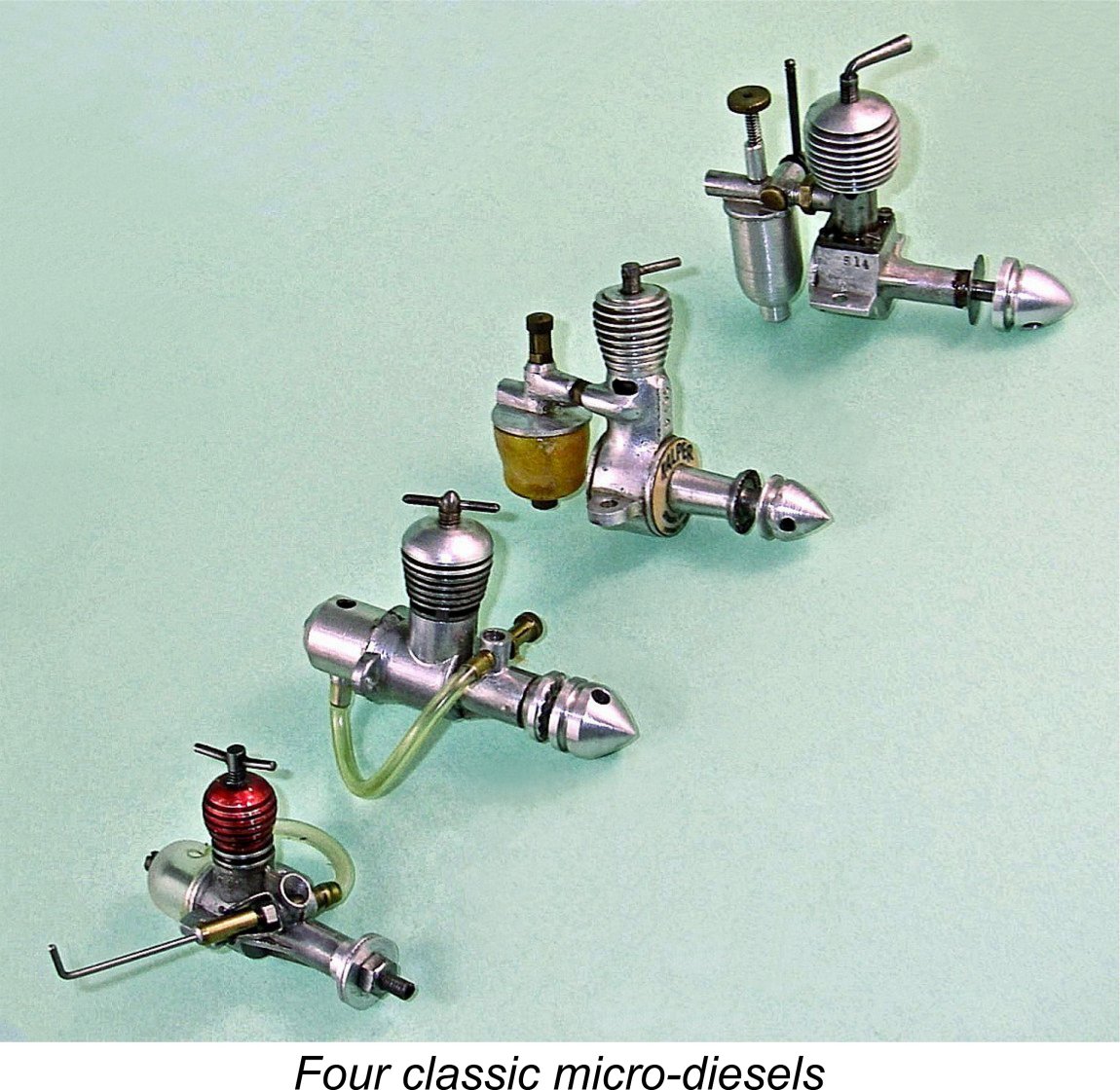 There’s an undeniable fascination attached to working mechanisms of all kinds which are created to be as small as possible while still performing the same functions as their full-sized relatives. For those of us who take an interest in model engines, this is particularly true.
 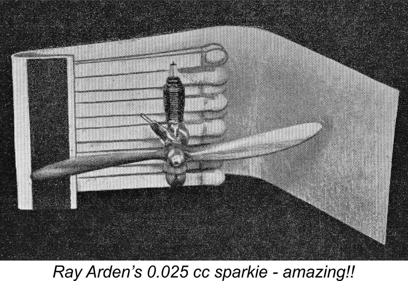 being generally viewed by commercial manufacturers of spark ignition engines as the practical lower limit for actual use in the field. However, a few mega-talented model engineers produced experimental one-off working sparkies at far smaller displacements.
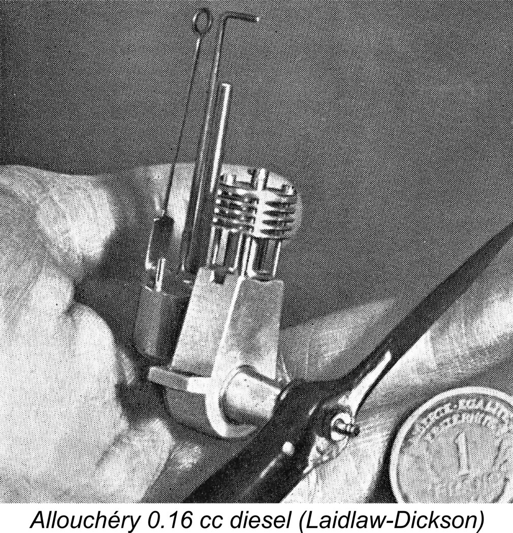 Although it was evidently not the “first ever” sub-miniature diesel, the first such unit to come to widespread prominence was the lovely little Allouchéry “Éclair” (Lightning) sideport diesel of 0.16 cc displacement. The 1 franc coin in the accompanying photograph has a diameter of 23 mm.
  Harry Fjellström
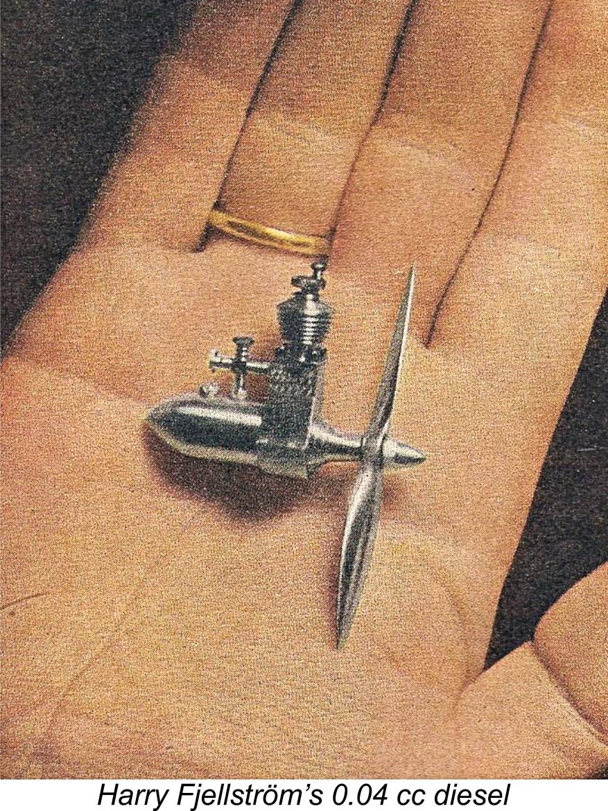 Thus encouraged, Harry now took what was to prove to be his final step towards the sub-miniaturization of the model diesel. The resulting engine was completed during the latter part of 1946 and must surely stand as one of the most remarkable model engineering productions of the early post-war period. As before, it was based very closely on the original Rogstadius drawings, although it incorporated a few modifications of Harry's own devising. However, the truly astonishing thing about it was its tiny size. The bore and stroke were 3.15 mm and 5.2 mm respectively for a displacement of only 0.040 cc! The engine weighed a mere 9.5 gm ready to run. Like all of Harry’s other productions, this tiny unit ran very well indeed, turning its hand-made aluminium alloy airscrew at over 5,000 rpm.
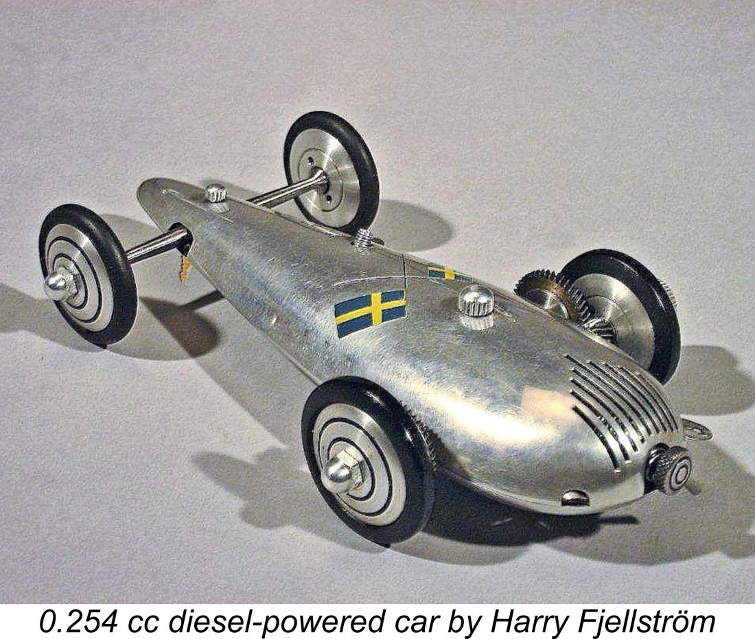 Harry was approached by others having an interest in seeing his little marvels enter series production, but he declined all such overtures. His view was that the required levels of precision were such that the engines could not be produced in quantity at anything approaching a rational price.
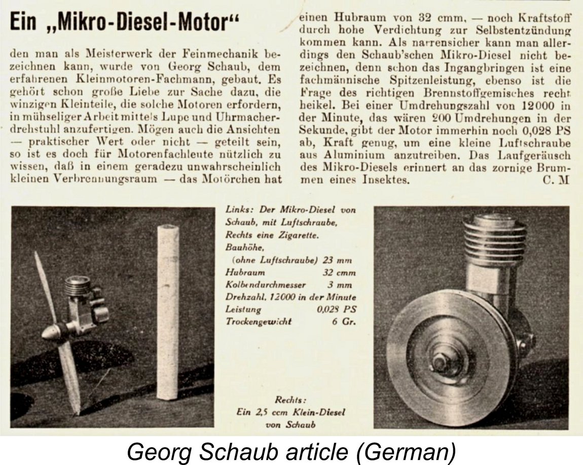
 One of England's more notable model engineers both before and after WW2 was an individual named
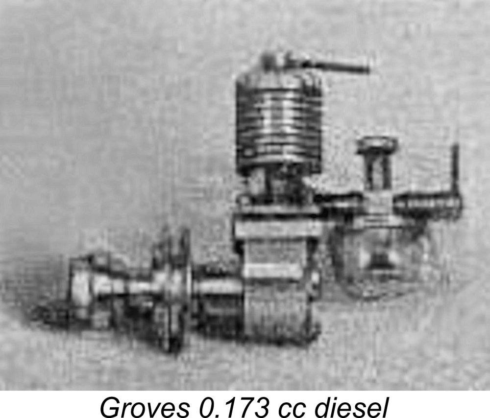
 During the conflict of WW2, model engine design and manufacture in Britain had unavoidably ground to a complete halt as other priorities engaged the attention of the nation. For this reason, British designers had been unable to direct much attention towards the further exploration of the model compression ignition concept which had been developed in Europe during the late 1930’s and the war years.
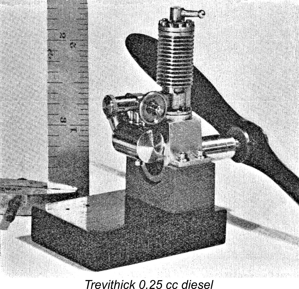
 By late 1947 Kemp had undoubtedly become aware of Trevithick’s successful experiments and had recognized the existence of a commercial market niche for a really small model diesel which could serve as a substitute for rubber power in lightweight models. He may also have been aware of Harry Fjellström’s successful efforts. Either way, by this time the practicality of making fully functional model diesel engines at very small displacements had been amply demonstrated.
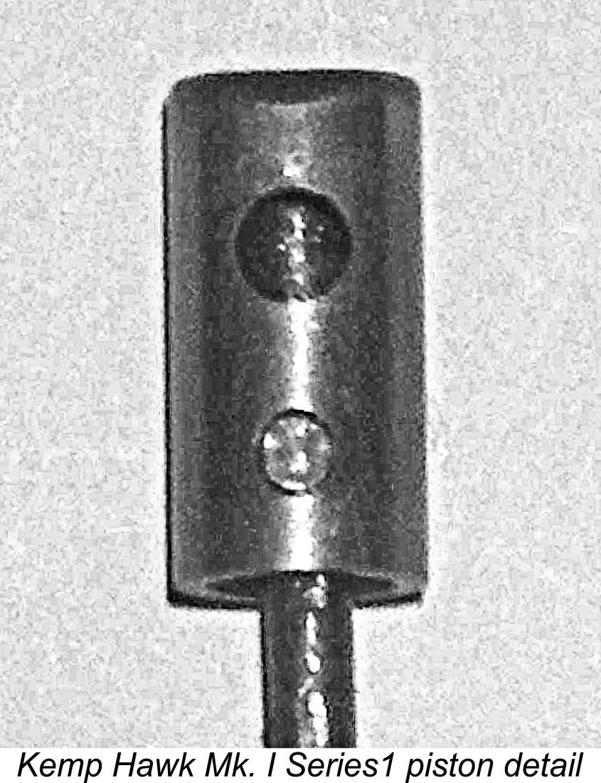
 After some 600 or so examples of the Series 1 variant had been produced, the design was revised somewhat. I would guess that the driving force behind this move was a perceived need for more power.
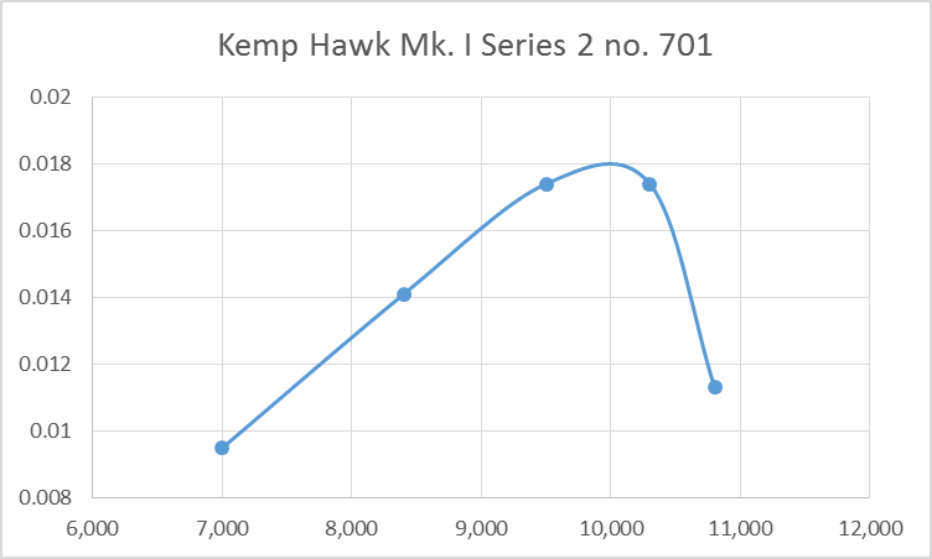
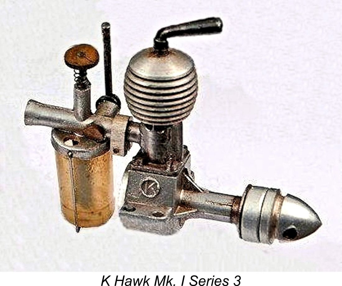 After taking over the design from Harry Kemp, Steward continued production of the sideport Hawk for a time, making a few changes of his own along the way. These changes resulted in the "K" Hawk Mk. I Series 3 model. The basic mechanical layout was unaltered, but the fuel supply system was significantly amended with a revised venturi design and a plastic tank in place of the former metal component. An additional strengthening web was added to the main bearing housing. In addition, the beam mounting lugs now featured two holes apiece instead of the former one. Finally, the "K in a circle" trade-mark was now prominently displayed on both sides of the case. Performance was essentially unaffected by these changes.
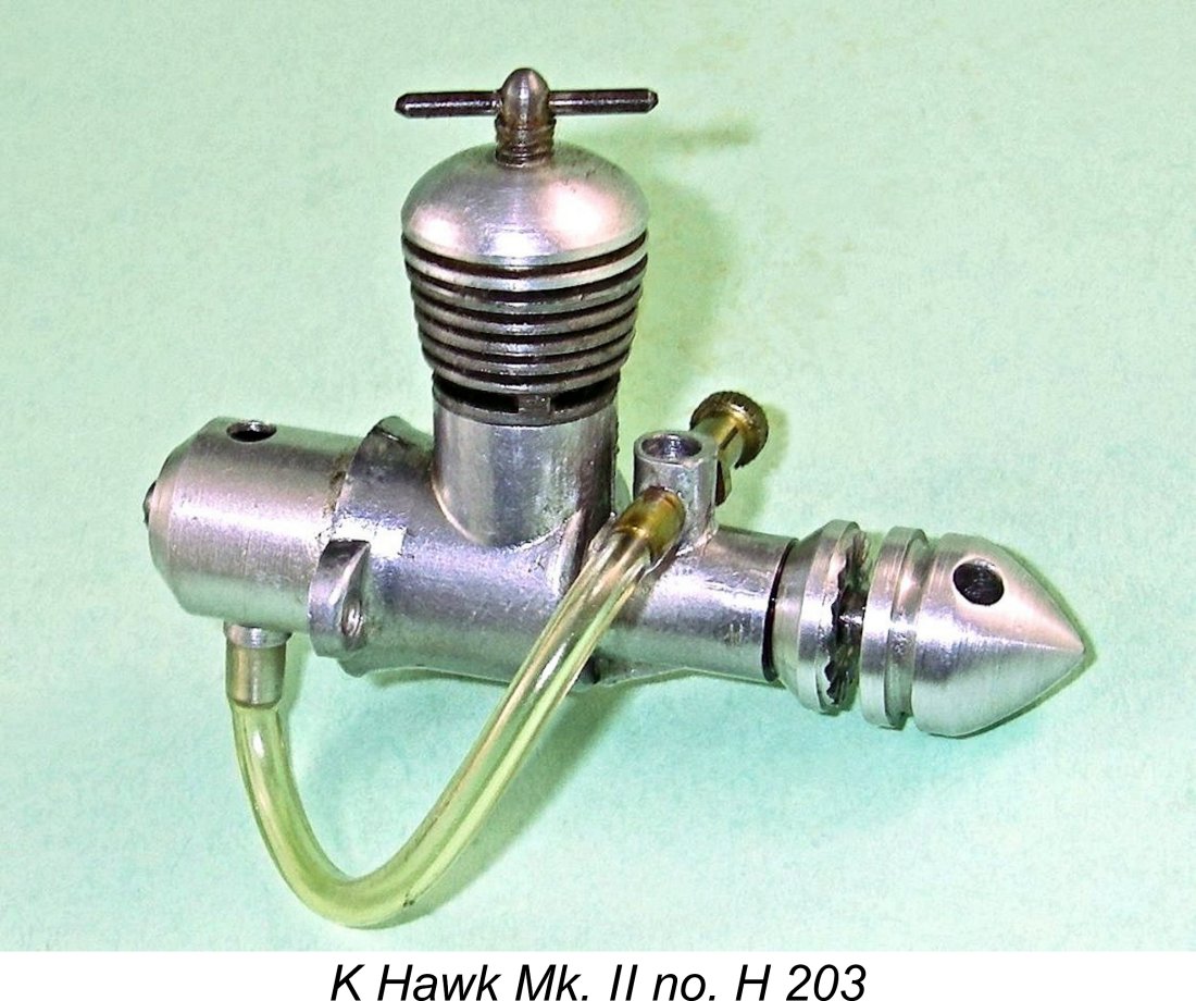 However, Steward was not yet done with sub-miniature diesels. In May 1949 the "K" Model Engineering Co. announced a completely revised model called the "K" Hawk Mk. II at an advertised price of £3 7s 6d (£3.37). This design was an all-new Len Steward original which owed absolutely nothing to the former sideport Hawk. It featured crankshaft front rotary valve (FRV) induction along with radial cylinder porting consisting of three sawn exhaust ports and three internal flute bypass/transfer passages between the exhausts. The cooling fins were turned integrally with the steel cylinder. The engine was arranged strictly for radial mounting.
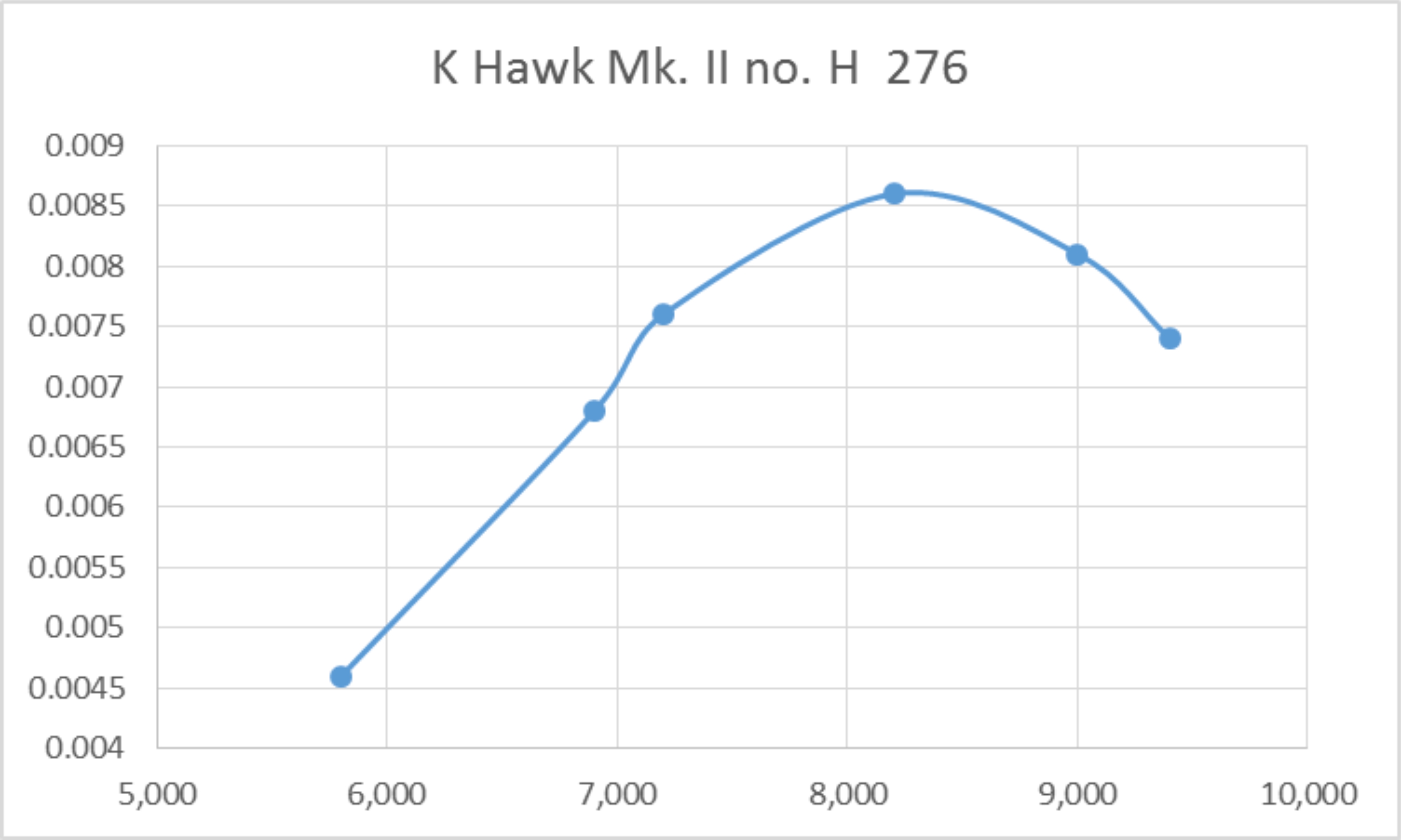
 generally did so if an example was available anywhere. The engine’s existence is irrefutably attested both by a series of advertising appearances and by its inclusion in Appendix II of Ron Warring’s early 1949 book “
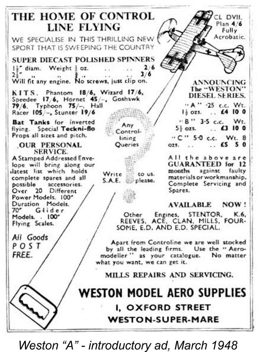
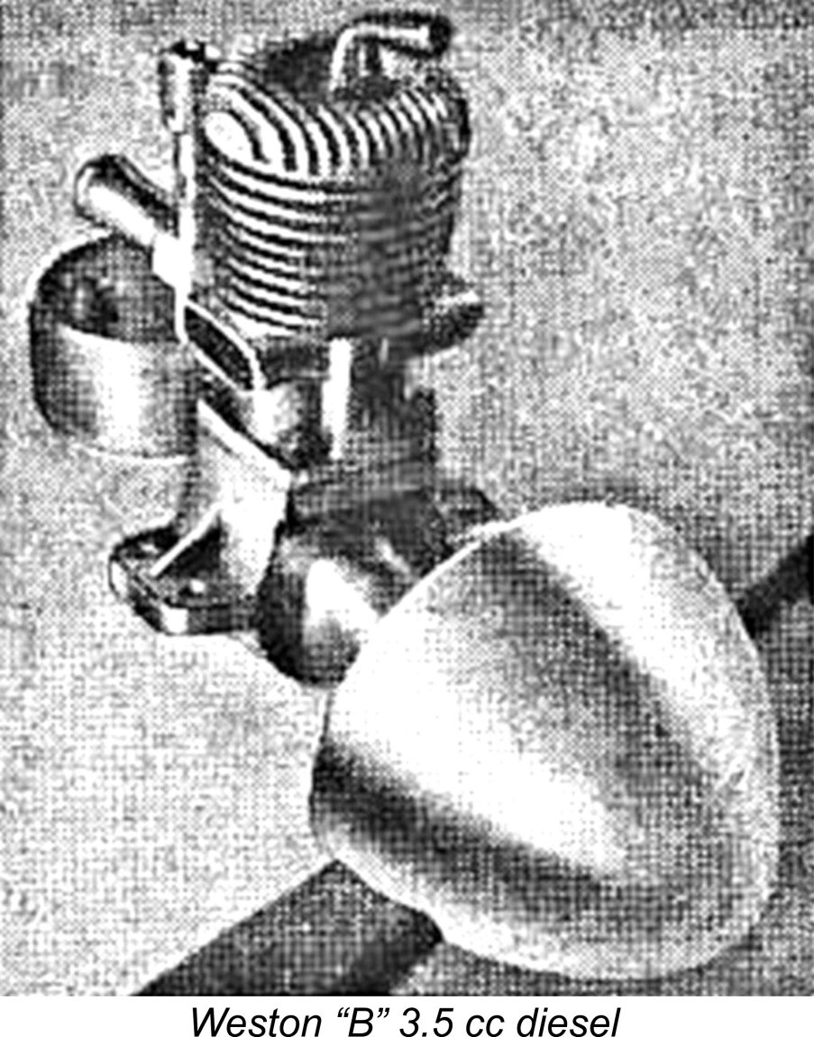 In the event, the only Weston diesel to make any kind of a mark was the 3.5 cc "B" model, of which a few examples reportedly survive today. Chris Coote was kind eough to contact Phil Darke, who was a member of the Weston Control Liners club during the late 1940's and early 1950's when it was led by Bill Evans. Phil recalled accompanying Bill to local Western Area contests at Lulsgate Bottom aerodrome (a former RAF fighter base which is now Bristol International Airport).
 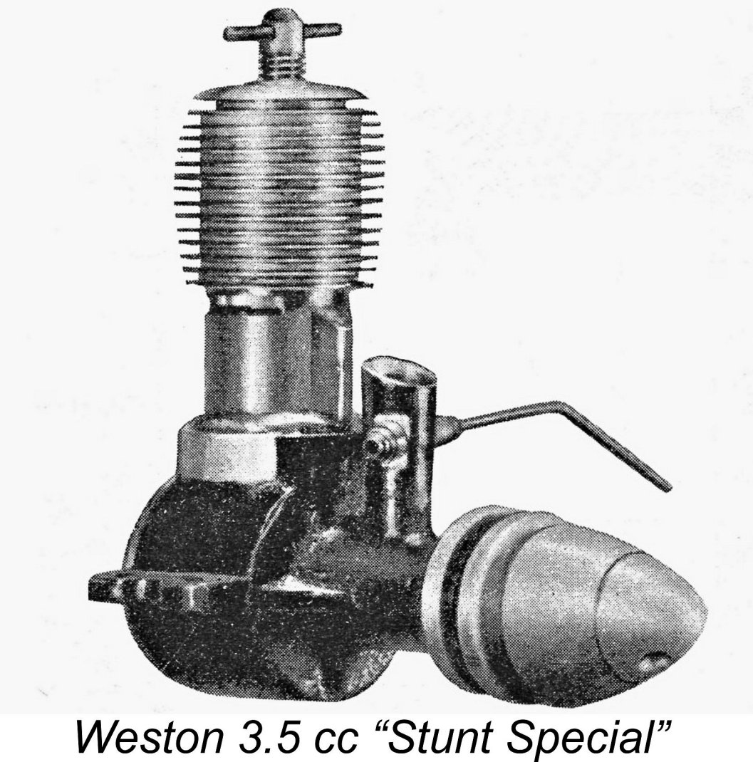 As of 1949 a significantly amended Mk. II FRV version of the 3.5 cc model called the Weston "Stunt Special" was being touted by the company, with no further mention of the Weston “A”. The Stunt Special was actually the subject of a
 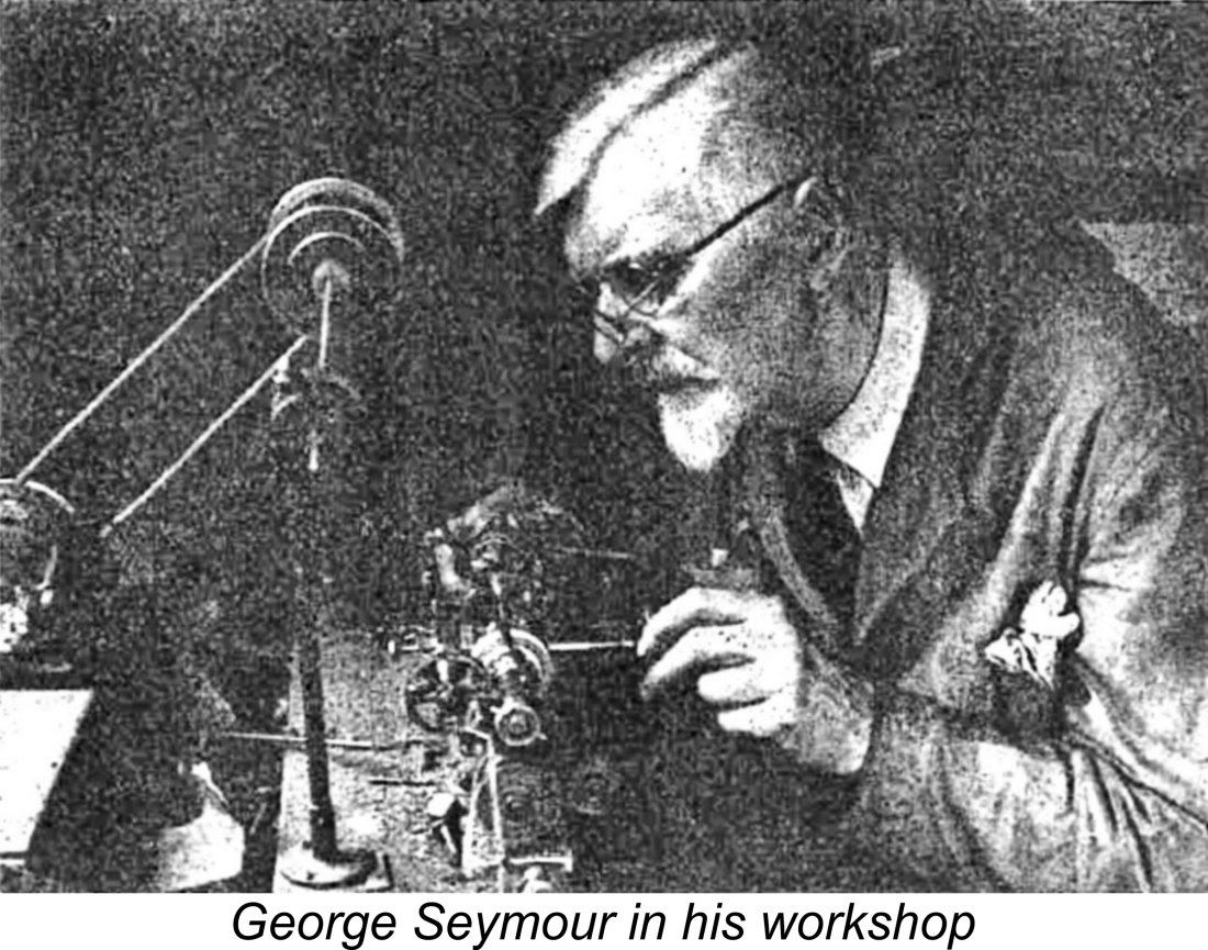 George Seymour (1884-1951) was a well-known and highly respected member of the model engineering community in the south coast area of England. In 1937 he had established a small precision engineering business called Seymour, Hylda & Co. The company operated from Seymour's residential address in Portslade, a western suburb of Brighton in Sussex.
 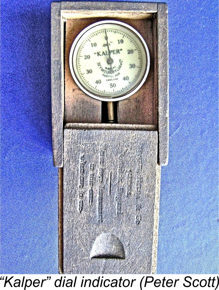 The company’s full name was Seymour, Hylda & Co., Engineers’ Instrument Makers. Its main business prior to 1947 seems to have been the manufacture of small precision instruments for use by model engineers and the like. One of its best-known products was the “Kalper” miniature dial test indicator which had appeared by 1939 and was very popular among the model engineering community. The origin of the name “Kalper” is unknown and likely to remain so. My thanks once again to Peter Scott for the provision of the attached image.
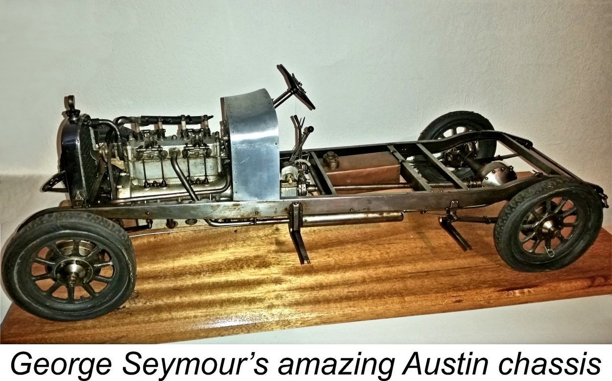 George Seymour was an unusually talented and painstaking model engineer. One of his most famous achievements was a superb working scale model of an Austin 12 car chassis, complete with operational scale-model four-cylinder engine and a fully functional gearbox. This remarkable creation earned Seymour a Silver Medal at the 1947 “Model Engineer” Exhibition. What, one may ask, did it take to win a Gold?!? Thanks to Miles Patience for providing the accompanying image.
 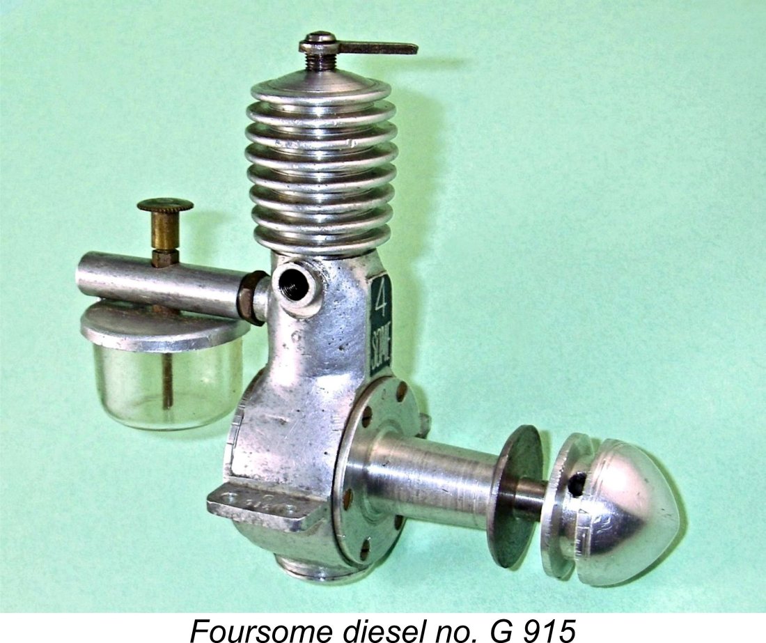 According to his obituary which appeared in the June 7
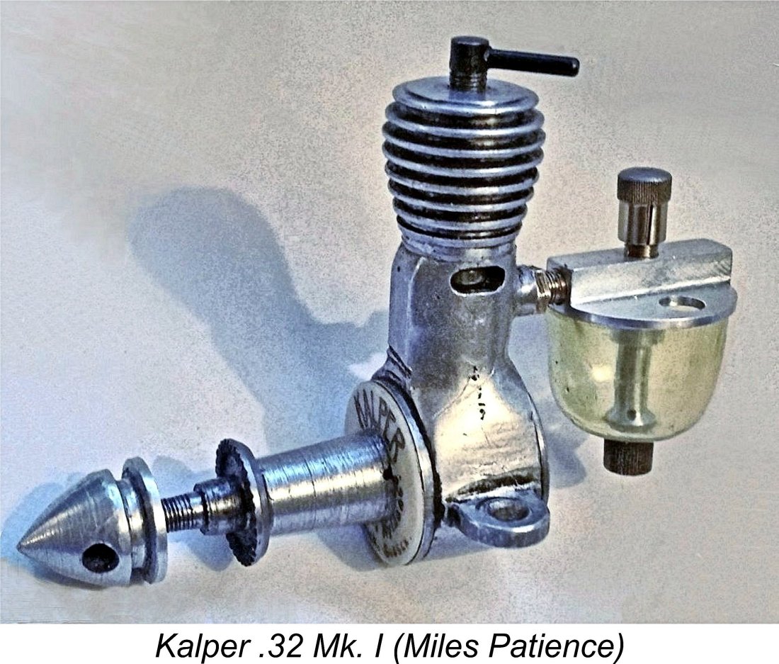 The next engine to emerge from George Seymour’s drawing board in mid 1948 was very directly connected with him! This was the
 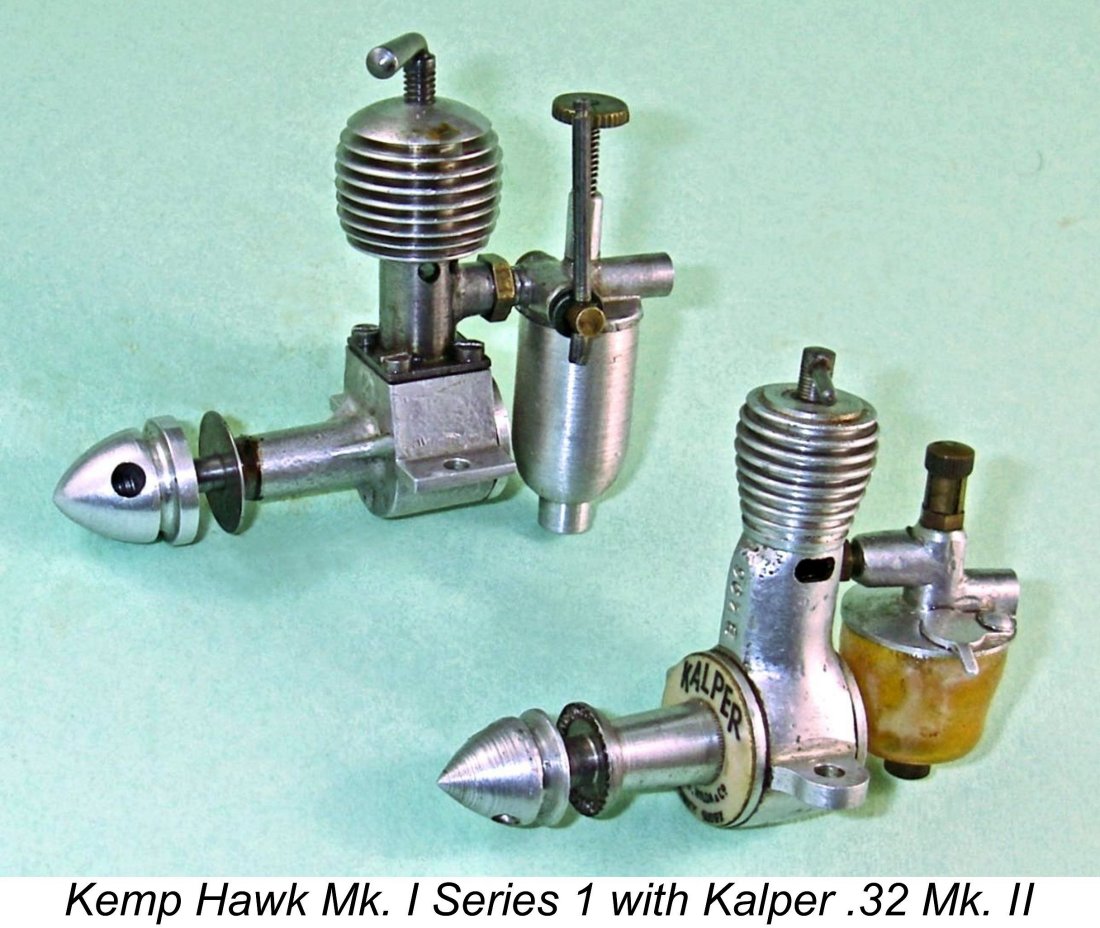 One of the most remarkable attributes of the Kalper .32 is its tiny size for its displacement. Despite its very long stroke, it is an amzingly compact engine. As the attached image will show, it's actually no larger than the 0.193 cc Kemp Hawk Mk. I Series 1, which has a significantly smaller displacement.
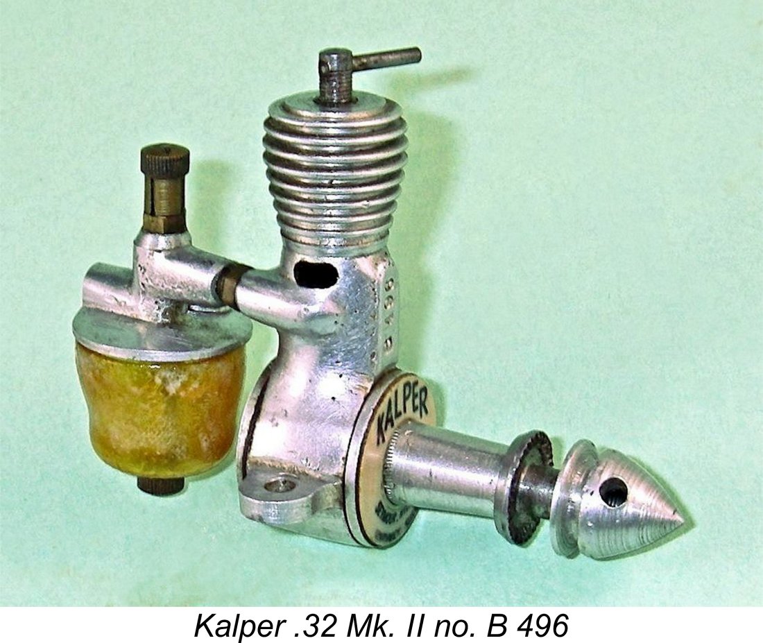
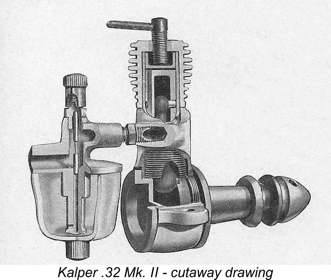
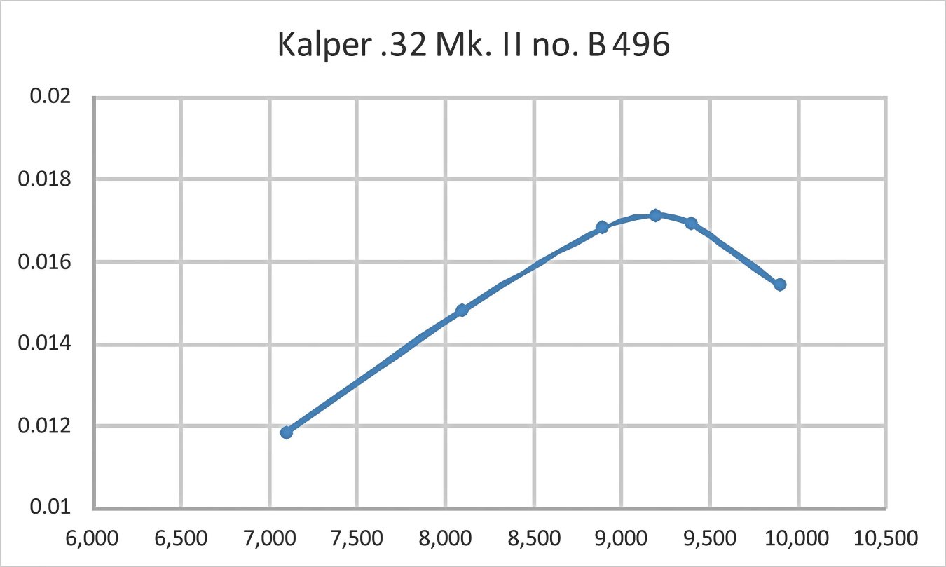
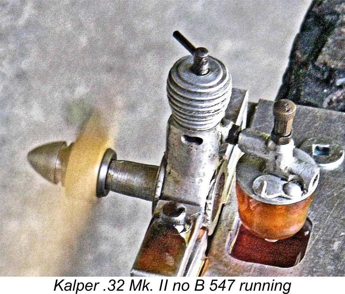 The little Kalper seems to have been quite highly regarded among the British sport and scale free flight community - deservedly so in my opinion. My previously illustrated example no. B 496 was another of Laurie Ellis's purchases, being obtained from Arthur Mullett in early 1950. Laurie used it quite a bit in small free flight models, but it remains in excellent condition, as does my other example no. B 547.
 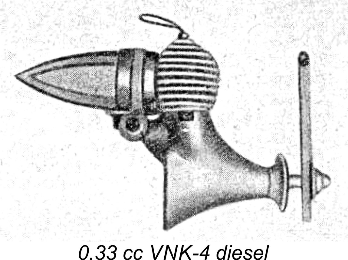 In 1937, before the war had even begun, the Russian authorities had established a model development facility called (in English) the Central Aircraft Modelling Laboratory (CAML) in Moscow. Staffed by the most experienced available aeromodelling specialists, this facility was destined to oversee the development of many of the Russian model engine designs which were to appear during the following three decades.
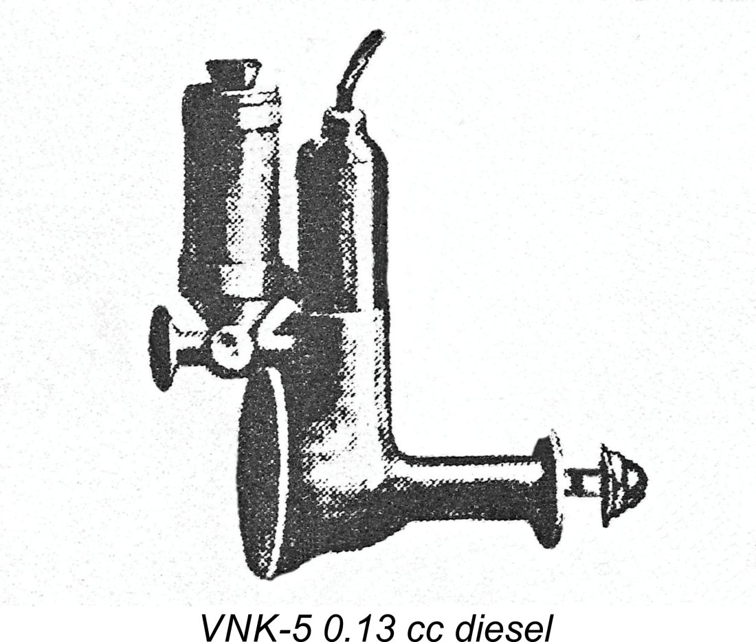 Their fellow model engine designer
 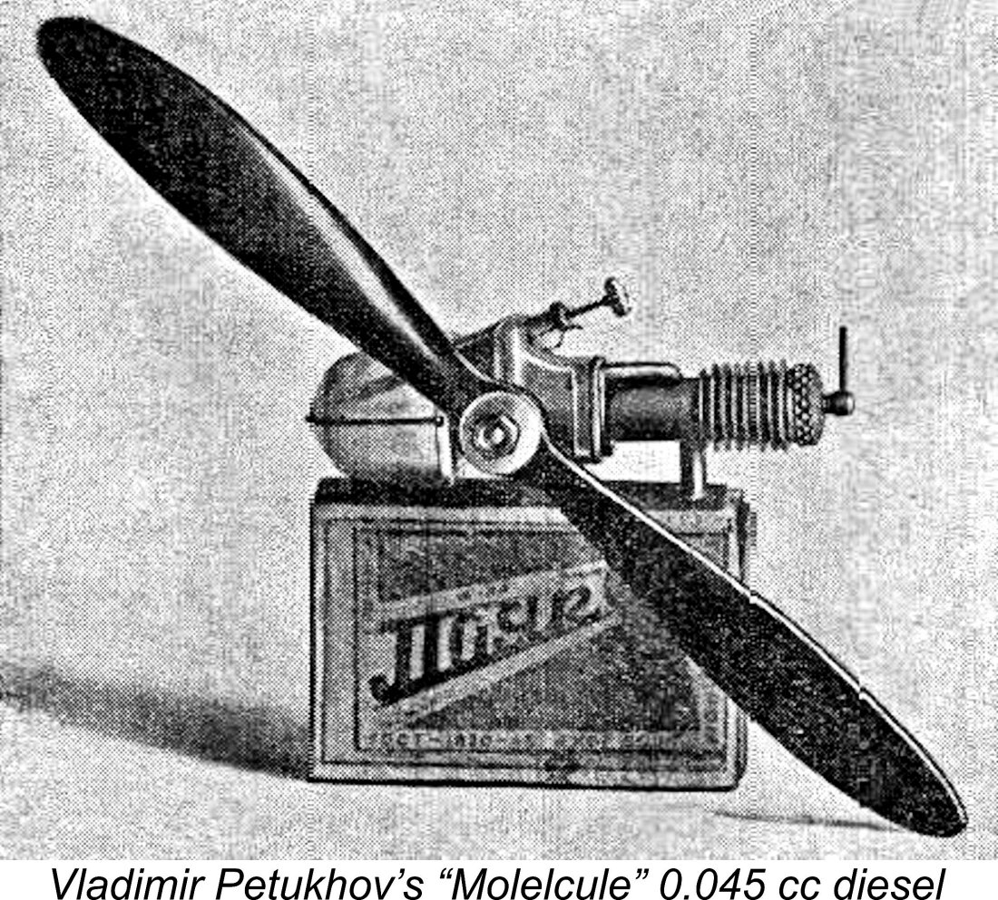 Petukhov’s competitive instincts seem to have been greatly stimulated by Bashkin’s success. It’s also possible that he had heard about Harry Fjellström’s remarkable 0.04 cc diesel discussed earlier. Anything that a Swede could do, a Russian could do just as well!!
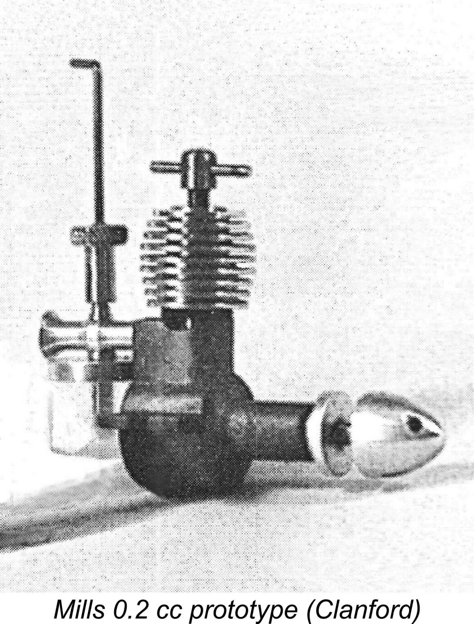 As readers of my separate article on
 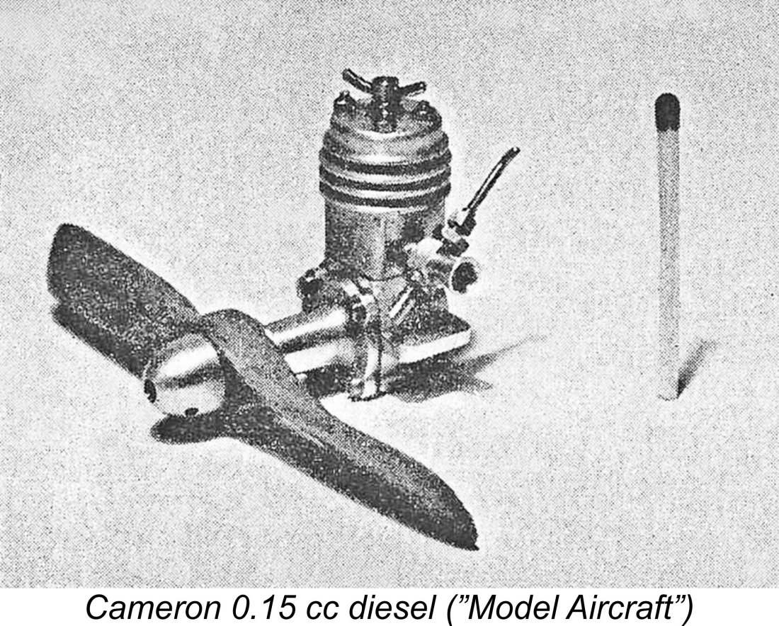 The Cameron 0.15 cc diesel was apparently a one-off which which never saw series production. We only know about Cameron's little gem thanks to its having been included in Peter Chinn's regular column in the February 1953 issue of "Model Aircraft". In that article, Chinn provided a number of details of this little creation, along with the image which is reproduced here. It was a sideport diesel having a somewhat unusual side intake featuring a surface jet fuel supply system. Bore and stroke were 3/16 in. (4.76 mm) and 5/16in. (7.94 mm) respectively for a displacement of 0.145 cc.
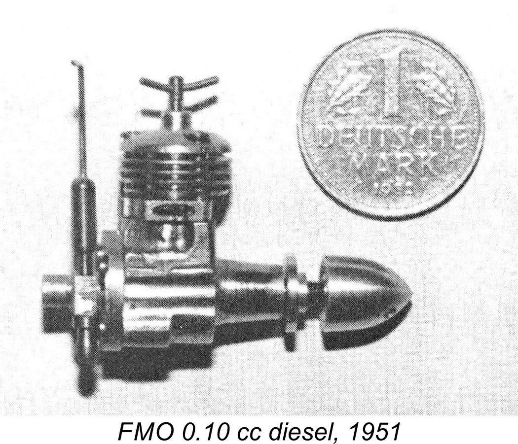 Hermann Fricke was a German watchmaker and toolmaker who developed an interest in the construction of unusual model engines. Beginning in 1951, when he was around 27 years old, Frick constructed a series of highly individualistic diesel engines, including six single-cylinder units, thirteen opposed twins, three in-line twins and one three-cylinder radial model. Fricke did all of the work himself, including making all of the dies and tooling as well as doing all of the machining. He was still active in the 1990's, producing another opposed twin and two micro radial designs. His engines were assigned the FMO trade-mark, standing for Fricke Motors.
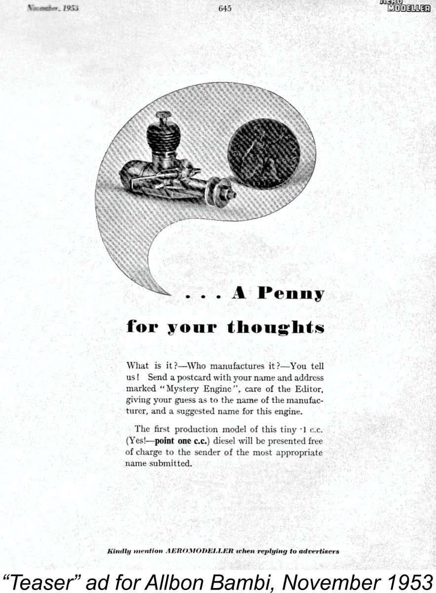
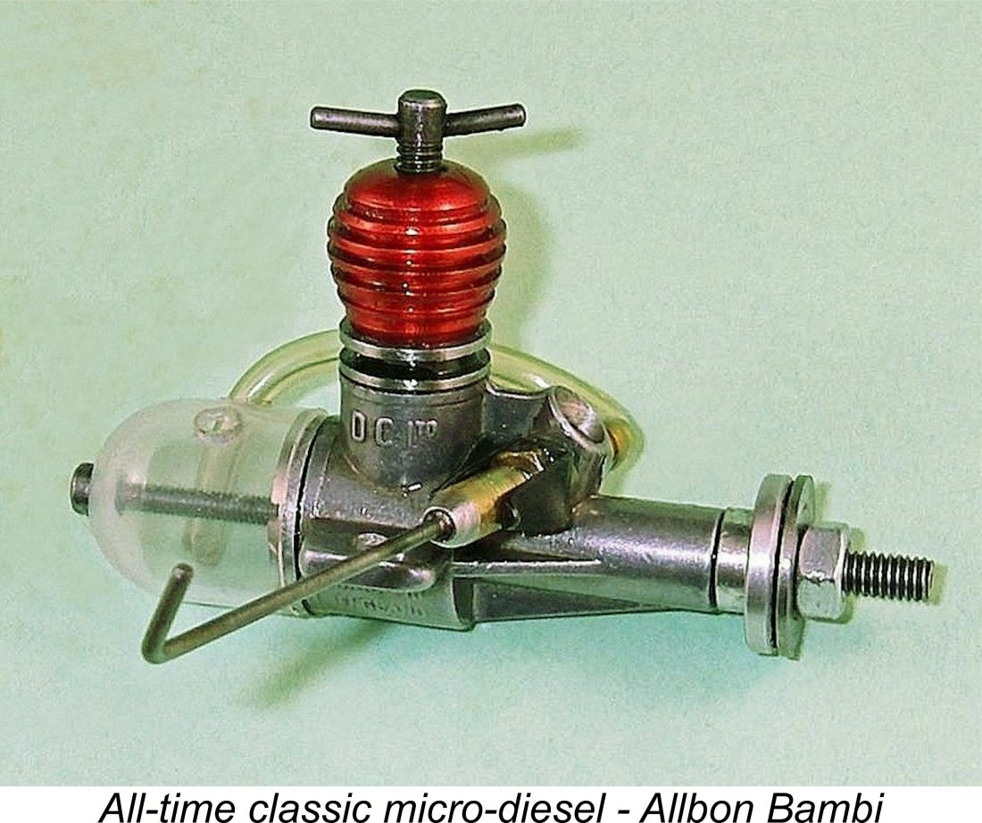
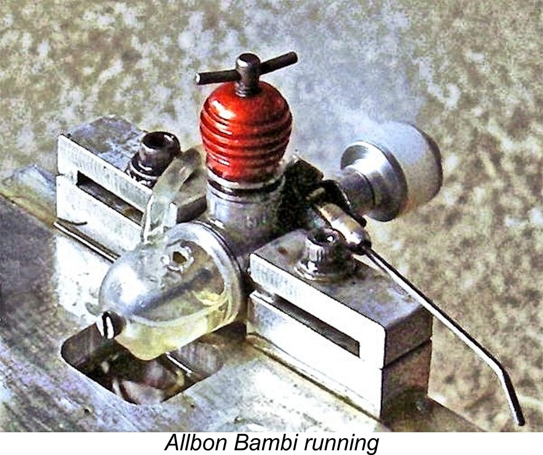 My own testing of a fine example of the Bambi which has been expertly rebored by my talented mate Dave Jones of Hervey Bay, Queensland, Australia has confirmed that the Bambi is indeed a perfectly useable little engine. Once the right compression and needle valve settings have been established, the engine starts quite readily. Injection of a single drop of fuel into the intake works very well in lieu of a port prime, and it’s best to “hit” the prop over compression in team-race style to achieve quick results (first checking to make sure that you’re not in or close to a hydraulic lock!). If you do this, the Bambi invariably starts in very short order and is very easy to adjust for best performance, albeit displaying a certain sensitivity to the needle setting. Peter Chinn actually commented upon this latter characteristic.
 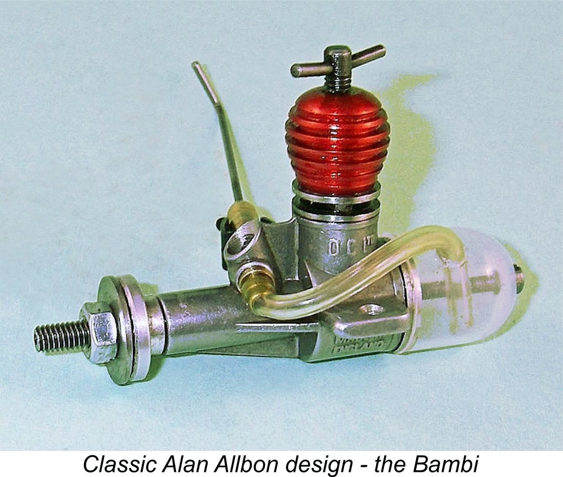 A Cox 4½x2 works very well indeed with the Bambi as a flight prop, turning at around 10,000 rpm on the ground - about 0.0066 BHP at that speed. This is quite consistent with Warring’s test figures. A Cox 4½x2 cut down and trimmed to 4x2 runs at around 11,400 rpm on the bench - about 0.0076 BHP at that speed. I'd guess that my test engine probably develops around 0.0078 BHP @ 12,000 rpm - fractionally over the 50 BHP/litre mark.
 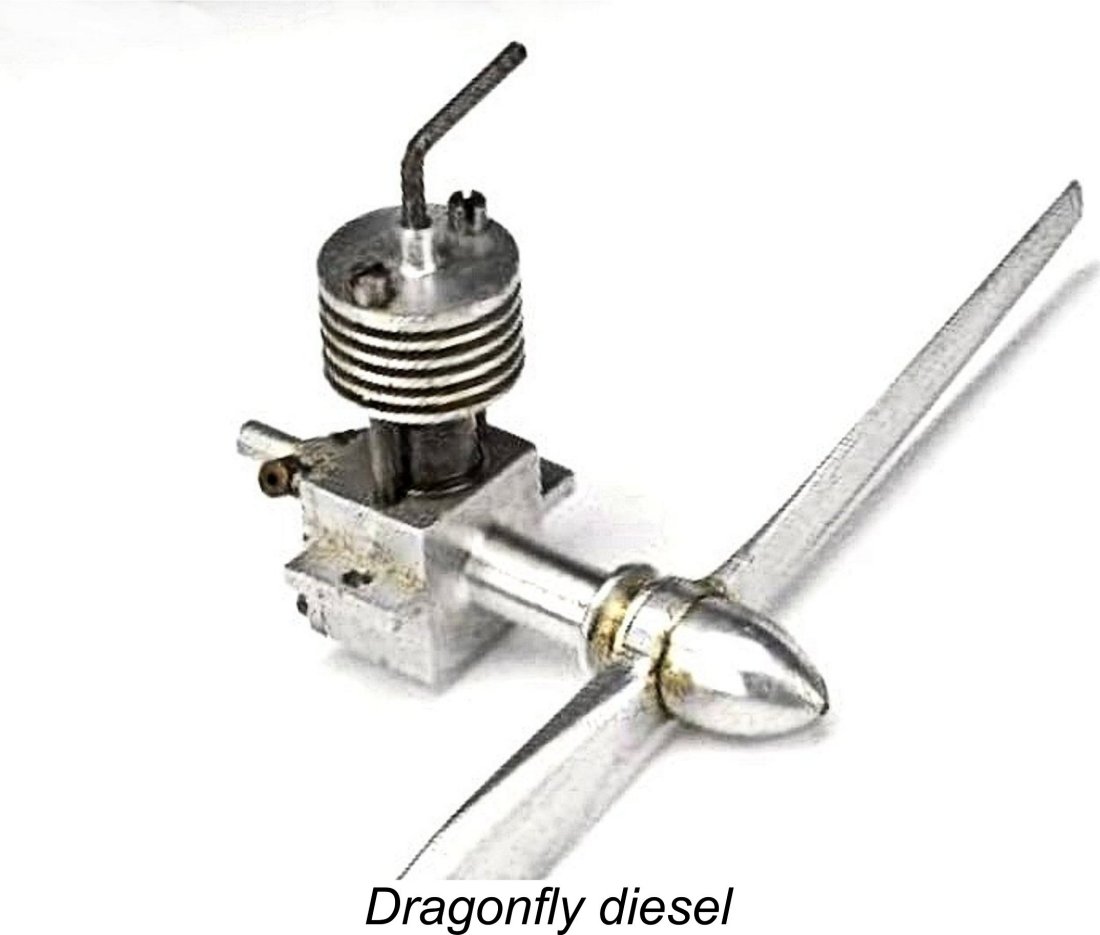 For our next entry, we’ll look at a little motor from an unknown maker which was apparently marketed exclusively by Henry J. Nicholls through his famous retail outlet at 308 Holloway Road in London. This was the
 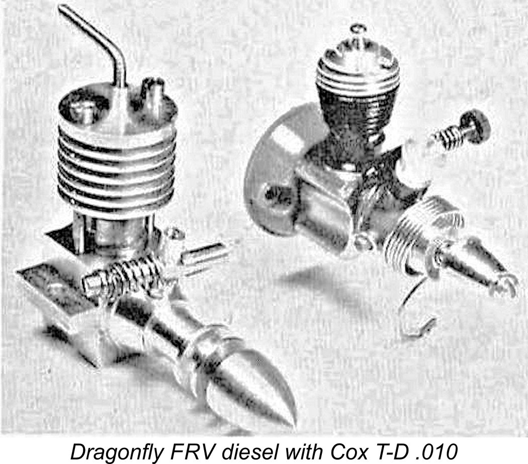 of the FRV Dragonfly with the Cox Tee Dee .010 appeared in the May 1961 issue of the same magazine. However, the majority of the units that were sold were RRV models. That May 1961 image represents the final appearance of the Drangonfly in the modelling media as far as I'm presently aware.
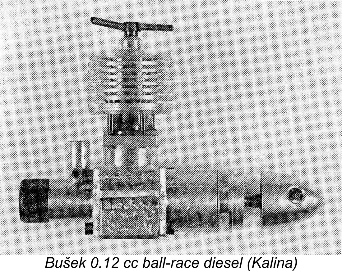
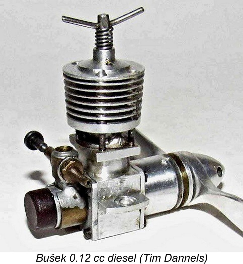
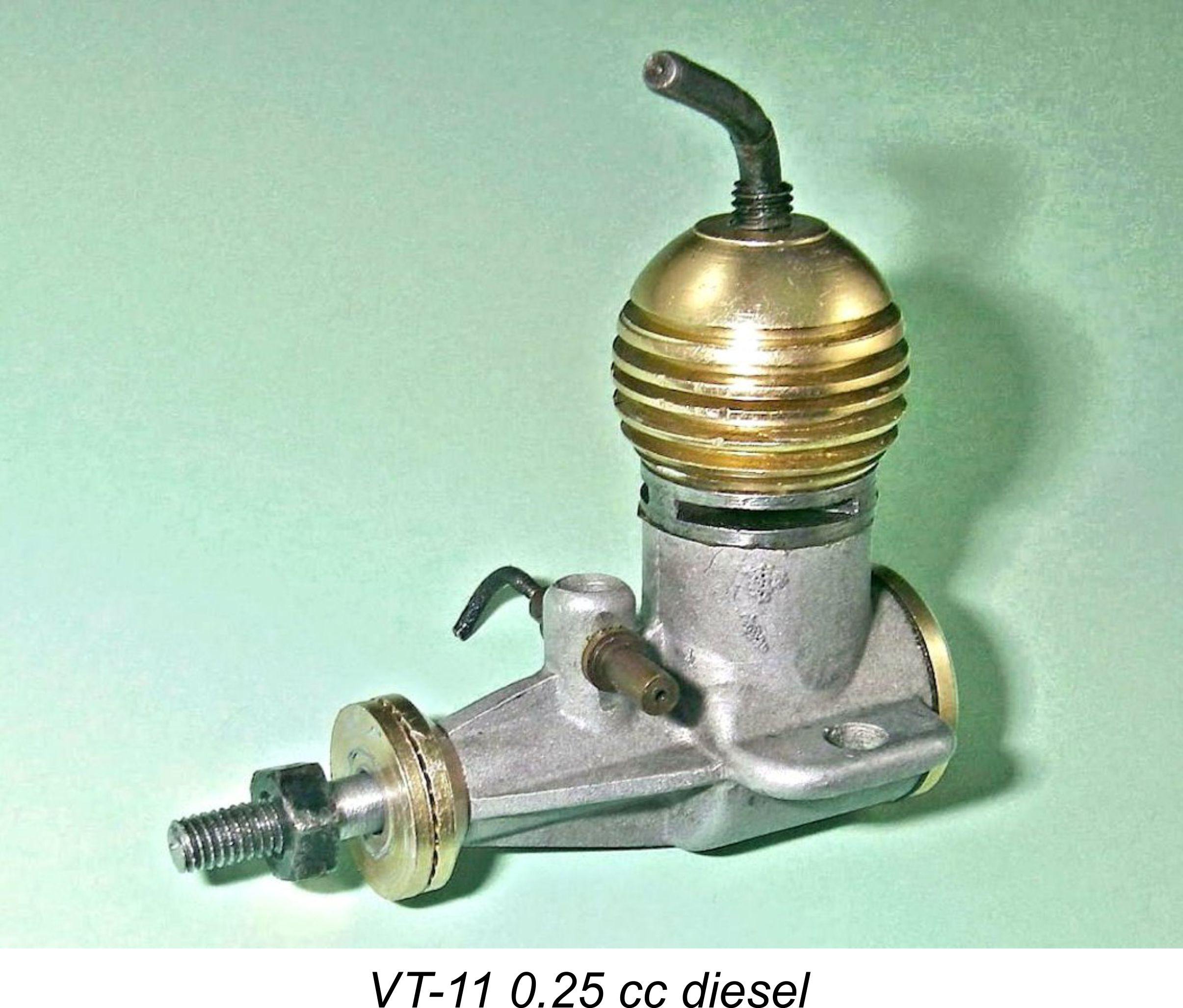 1958 saw the appearance of the first commercially-produced micro-diesel to emerge in the Soviet sphere of influence. This was the 0.25 cc VT-11 diesel from Budapest in Hungary. This cute little engine first came to the attention of modellers in Britain and elsewhere through its inclusion in the “Motor Mart” feature in the February 1959 issue of “Aeromodeller” magazine.
 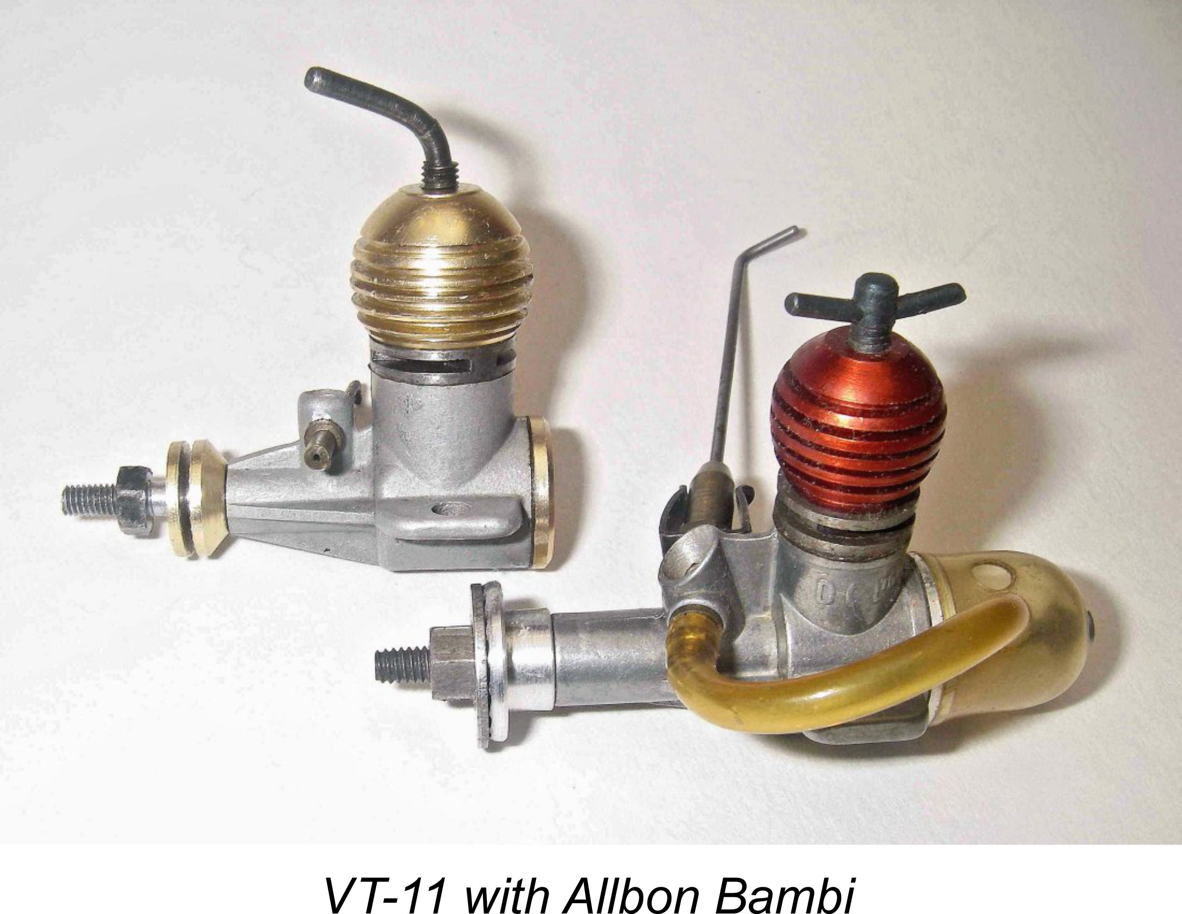 This very neat and compact little engine had over-square bore and stroke measurements of 7 mm and 6.2 mm respectively for a true displacement of 0.239 cc. Weight was a measly 18 gm (0.63 ounces). In terms of its design and construction it was very much a typical member of the Vella Brothers diesel family, albeit with a few simplifications in deference to its tiny size. The brothers' usual good standard of manufacture was in evidence in my example at least - the minute forged alloy con rod is particularly noteworthy. The cooling jacket, backplate, prop driver and prop washer were all anodized gold.
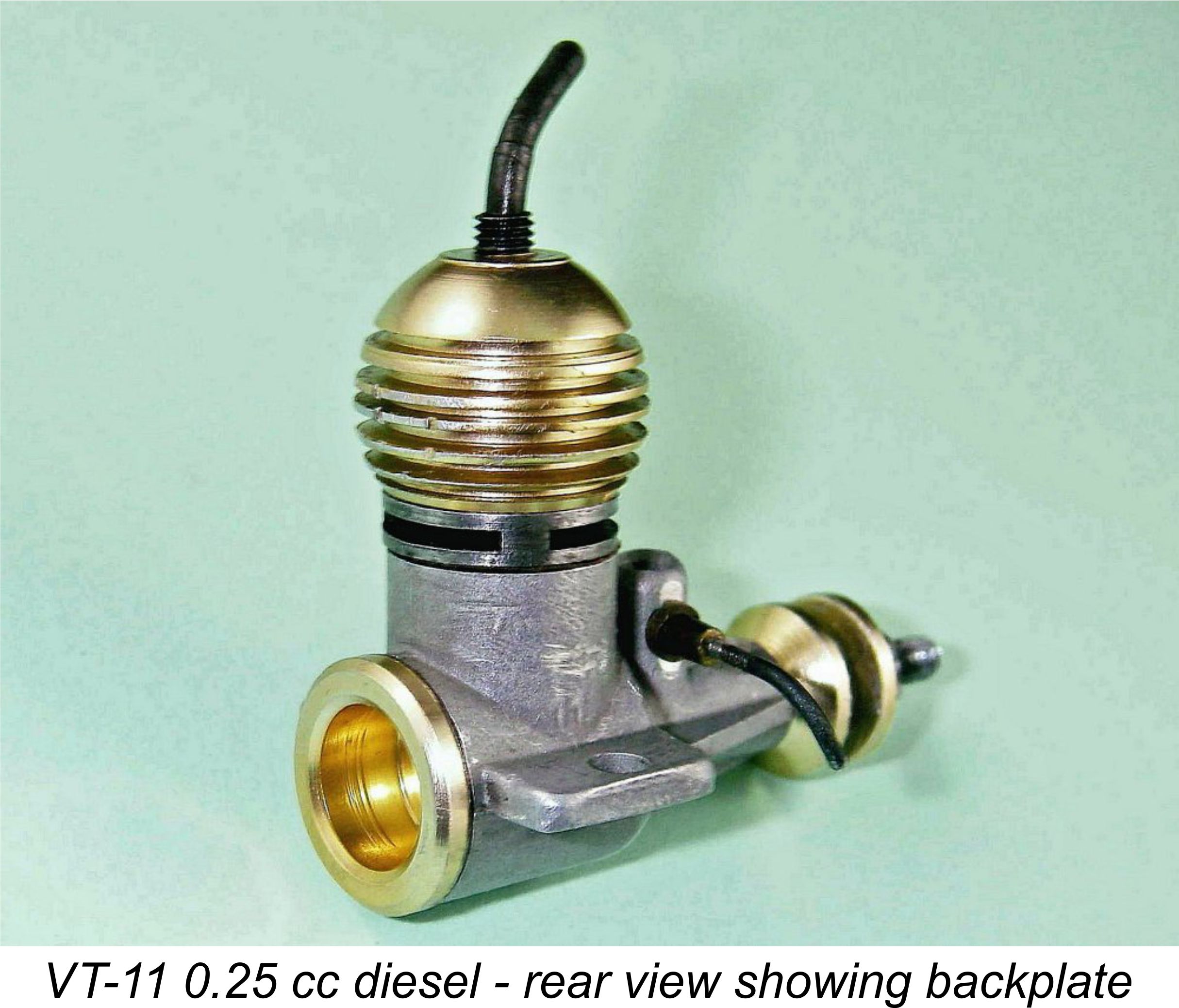
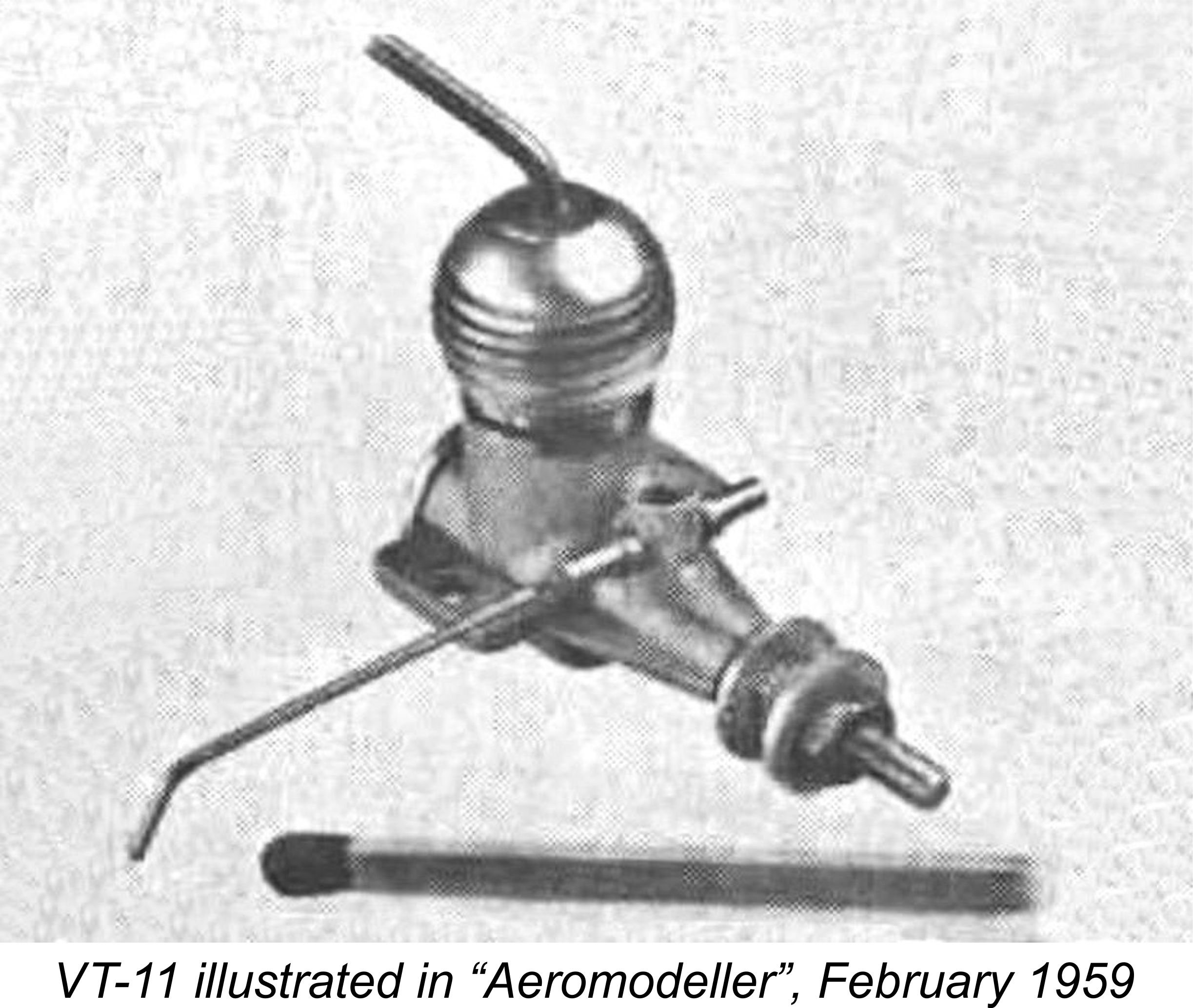
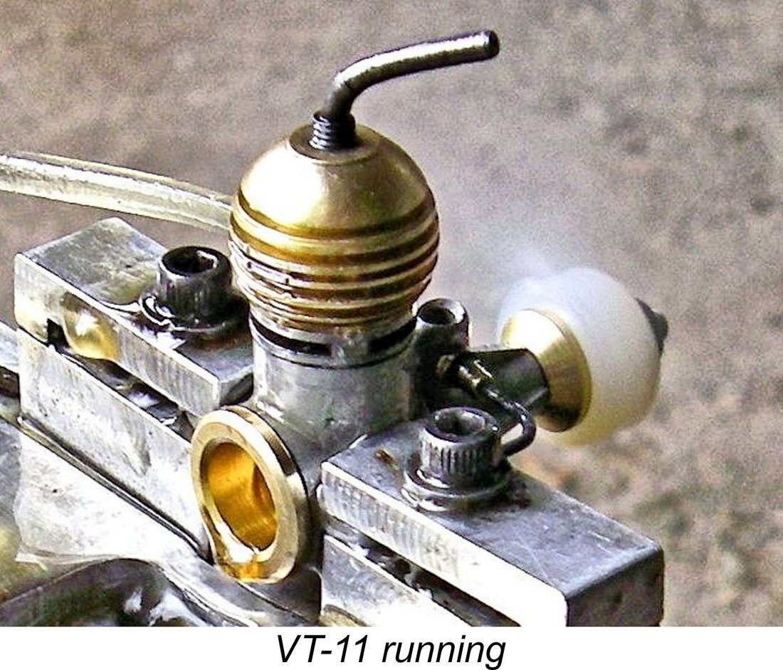
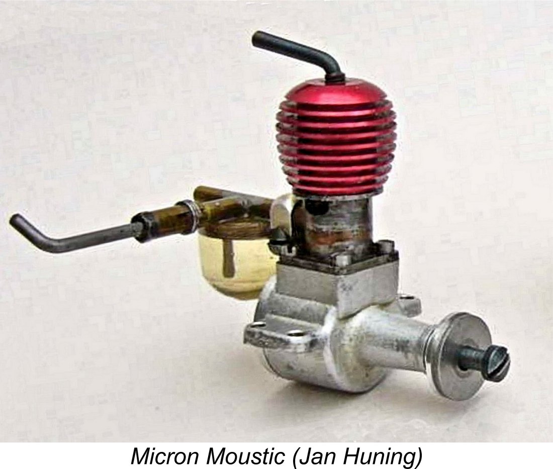 For the next entry, I have to abandon the previous protocol of listing engines under their designers’ name, because the name of the actual designer of the next sub-miniature model diesel to appear is somewhat obscure. The Micron company had been established way back in 1941 by André Gladieux of Paris, who had produced an impressive series of highly-regarded model diesels in a wide range of displacements. However, in 1951 Gladieux had sold the Micron company, which had subsequently merged with the rival Maraget company to establish the Micron-Météore marque. Despite this merger, some models continued to be marketed as Micron products.
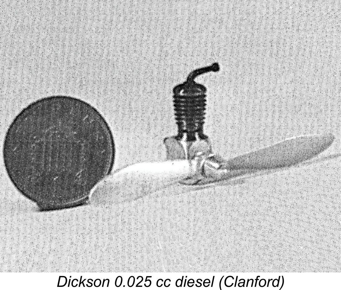
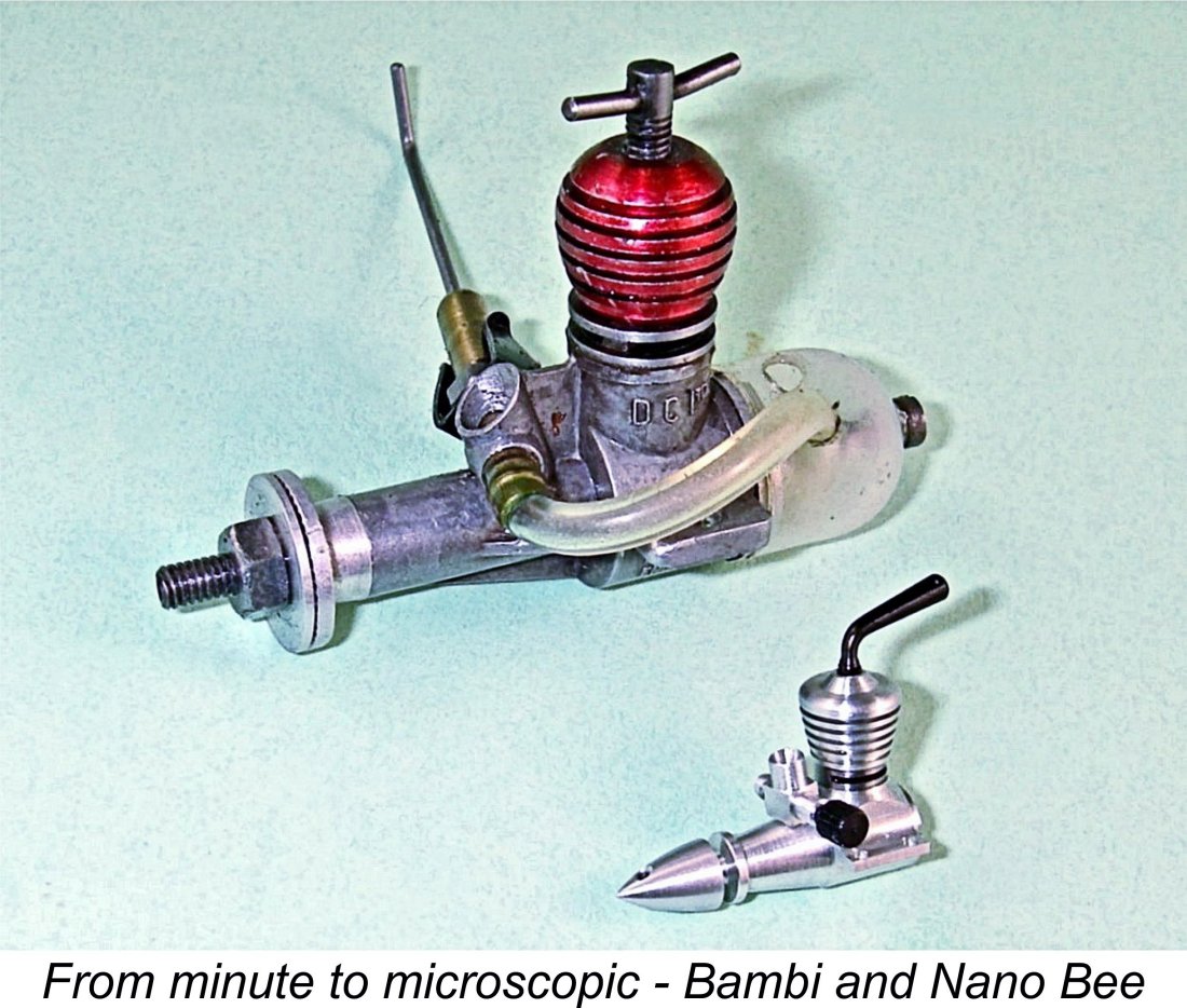 One later engine that I feel needs to be mentioned here in closing is the world’s “smallest ever”, because it sets the bar against which all the others must be measured. This is
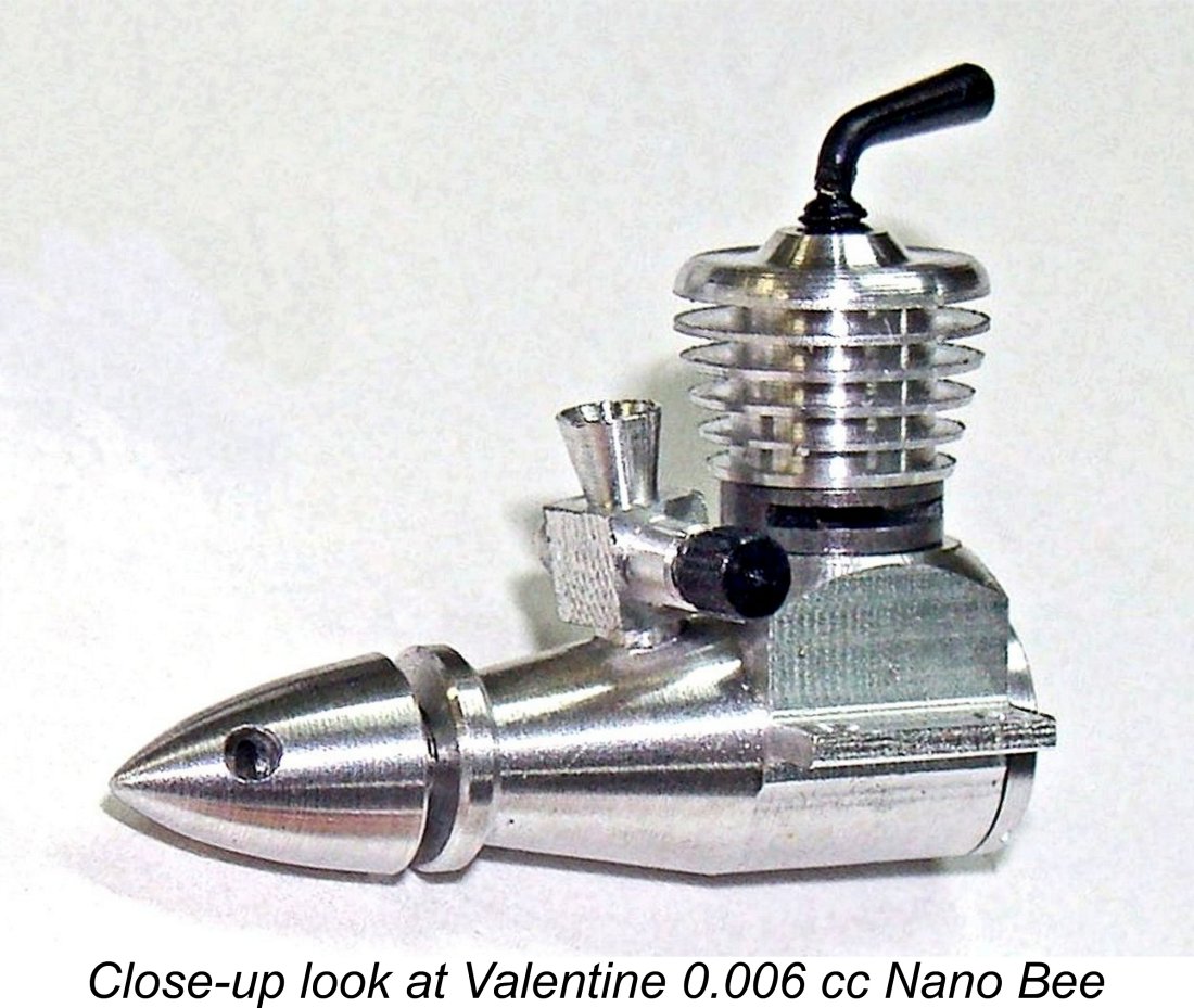
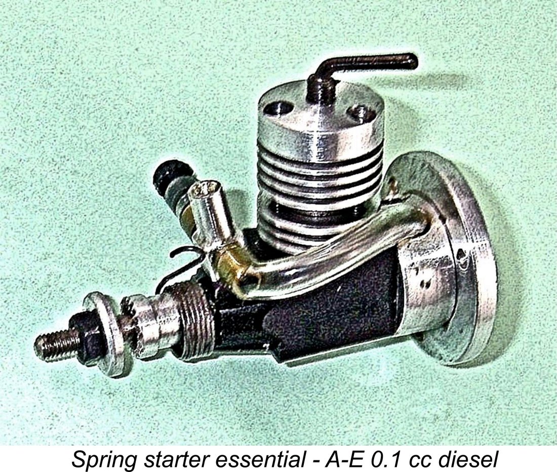
| |