
|
|
The 1 cc Kemp and K Diesels
In an earlier article to be found on this website, I evaluated the first attributed product of the new company, the 4.4 cc Kemp K4 diesel of early 1947. I say “first attributed” because there’s a slim and completely unproven possibility that Harold Kemp’s first model engine design was in fact the beautiful but fragile 6.38 cc Keil K6 spark ignition engine of 1946. A close connection between Kemp and Eddie Keil is attested by the fact that Keil was an early distributor of the Kemp engines. That said, the identity of the designer and manufacturer of the K6 has never been authoritatively confirmed. It must also be admitted that the K6 shows little evidence of Harold Kemp's later design and manufacturing styles.
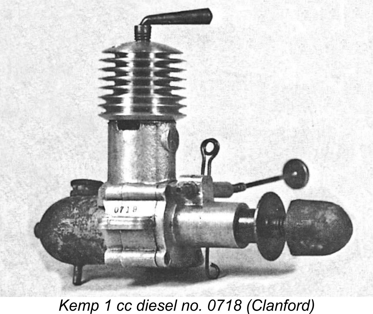
The K4 was soon joined by the 1 cc crankshaft front rotary valve (FRV) model which was the main subject of the initial version of the present article. This model seems to have appeared in around April 1947, a few months after the K4. This article's initial focus on the original Kemp 1 cc model was prompted to a certain extent by the need to correct some misinformation that has got out there. On page 35 of his very useful and entertaining but occasionally misleading “Collector’s Guide to Model Aero Engines”, the late O. F. W. “Peter” Fisher referred to the existence of “the rare K 1.9”, which The engine which appears in Fisher’s incorrectly-captioned illustration is undoubtedly an example of the 1 cc model which is the subject of the present article. It bore the serial number 762, which fits well with the known sequence. Another reason to take an interest in the 1947 Kemp 1 cc diesel is the rather odd fact that it was replaced in March 1948 by the Kemp (later K) Eagle 1 cc model, which was a sideport engine. This reversed the usual trend, which generally saw manufacturers of sideport engines making the move to rotary valve designs rather than the reverse. AMCO, Allbon, Davies-Charlton and E.D. all come immediately to mind. The circumstances surrounding Harold Kemp’s strange "reverse" design progression with his 1 cc models merit investigation. After the take-over of Kemp Engines by Len Steward's K Model Engineering Company in mid 1948, a further 1 cc design called the K Eagle Mk. II made its appearance before the end of that year. This was once more an FRV design, albeit now featuring updraft induction. It sold for a remarkably low price, but only remained on offer for some 4 or 5 months. It proved to the the final 1 cc diesel in the Kemp/K series. I won’t go any further into the background to the appearance of the original Kemp 1 cc diesel, since I’ve already covered the full history of the Kemp venture in other articles, including the one about the K4 diesel mentioned earlier. In addition to that article, I’ve also written about the Kemp Hawk, the K Vulture and the K 2 cc models in other articles which may still be accessed either here or on the late Ron Chernich’s “Model Engine News” (MEN) website. The complete story of Kemp Engines and its successor company, the K Model Engineering Co., may be found in those articles. However, full bench tests of the two 1 cc designs which followed that original Kemp 1 cc model were not included in those earlier texts. My purpose in writing this comprehensively revised article is to complete the cycle by bringing test results for all three Kemp and K 1 cc models together in a single reference. I'll review each model in turn in the order in which they appeared. But first, a little context will be helpful for any readers who are new to the Kemp and K engines. Context The concept of utilizing compression ignition in miniature aero engines originated in pre-WW2 Europe. Although it became well established on the Continent during the war years, the British focus on the conduct of the war resulted in the principle not becoming widely known in Britain until the conclusion of the conflict. As a result, early post-war British developers of model diesels were playing catch-up behind a significant number of Continental designers, many of whom already had four or five years of experience as of 1945.
The first British diesels to reach the market in any numbers were the Mills 1.3, initially from Sheffield and later manufactured in Woking, and the Owat 5 cc fixed compression diesel from Bradford. These two models appeared more or less simultaneously in July 1946. They were followed later in the year by the B.M.P. 3.5 cc model from Bournemouth, the Clansman 5 cc diesel from Glasgow, Scotland and the Majesco 2.2 cc diesel from Parkstone in Dorset. E.D. joined the party in early 1947 with their 2 cc Mk. II sideport model, as did Harold Kemp with his previously-mentioned 4.4 cc Kemp K4 diesel. The FROG 100 diesel did not actually reach the market until late 1947, although prototypes had appeared at the Model Engineer Exhibition of December 1946. The AMCO .87 diesel made its debut in August 1947, with the 5 cc Davies-Charlton Wildcat Mk. I, the ETA 5 and the 2 cc Aerol Gremlin all appearing at about the same time. The original Kemp 1 cc diesel was thus released into a British marketplace which was just picking itself back up off the ground following WW2 and was very much in expansion mode at the time. Despite their relatively high prices in the context of the cash-starved early post-WW2 British economy, model engines were in such high demand that any engine which would start and run reasonably well most of the time and stay together while doing so was pretty much guaranteed a sale. Although Harold Kemp’s first engine, the 4.4 cc K4 sideport model, was evidently selling quite well, reference to the list previously presented here indicates that it was one of the larger diesels of the early 1947 period – only the Owat and Clansman 5 cc models were larger at the time. There was clearly a strong potential market for The Kemp 1 cc offering was preceded into the British small-diesel marketplace by the B.M.P. 0.9 cc diesel from Bournemouth. However, this sparsely-advertised unit did not make much of a mark on the national scene, evidently being marketed locally for the most part and falling by the wayside quite quickly. It is a mega-rare engine today. Kemp's main opposition came initially from the excellent Mills 1.3, which had quickly come to dominate the small-displacement diesel market despite its rather steep asking price of £5 5s 6d (£5.27). Neither the AMCO .87 nor the FROG 100 diesel reached the market until somewhat later in 1947. The mid 1947 Clan 0.9 cc diesel from Scotland never really made significant inroads into the British market south of the Border. Accordingly, at the time of its release the Kemp 1 cc diesel effectively had no domestic competitors in its displacement category. Partially for this reason, Kemp felt able to charge a price of £5 even for the 1 cc model, thus undercutting the Mills 1.3 by a small amount. This was still a very steep price indeed at a time when a man earning £8 a week before taxes would have been considered relatively well off. However, the novelty appeal of such small engines encouraged people to save up and buy them regardless, even at such a price. Kemp was evidently able to sell all that he could manufacture. Now that we’ve seen the Kemp 1 cc diesel launched onto the market, let’s have a look at the engine itself. Kemp 1 cc Diesel – Description
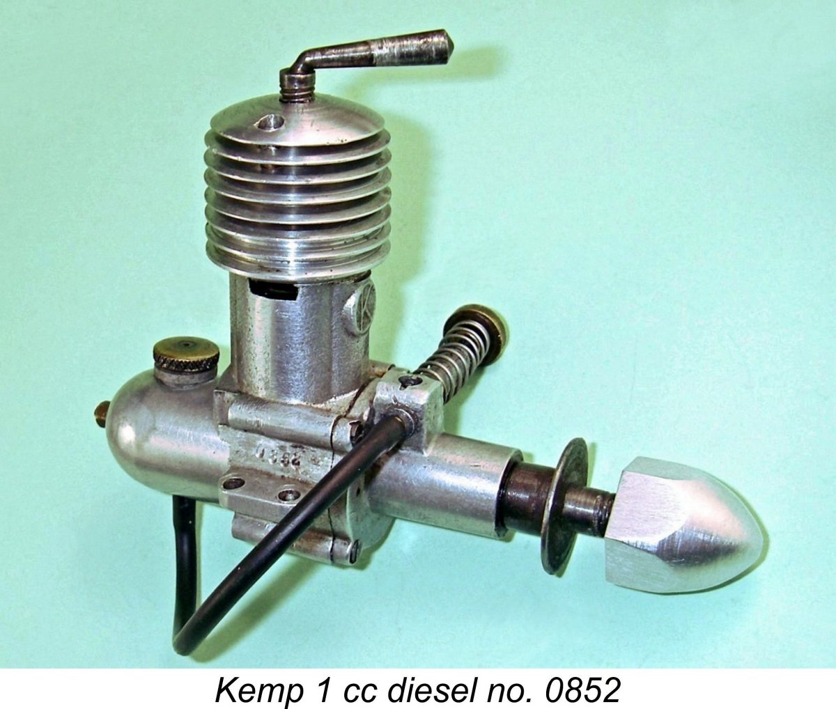
The manufacturers were clearly not too worried about exactly achieving the engine’s nominal 1 cc displacement – after all, they were not facing any competition displacement limitations. All-up weight as illustrated with fuel tank and spinner was a fairly healthy 110 gm (3.88 ounces). The engine was built up around a sturdy main casting which incorporated the crankcase, beam mounting lugs, bypass passages, exhaust ducts and backplate as a single unit. The upper portion of the casting above the exhaust ducts was externally threaded to accommodate the internally-threaded screw-on cooling jacket. The early examples of this engine used cooling jackets made from magnesium alloy, while later examples like that illustrated here featured aluminium alloy components. The steel cylinder was provided with two rectangular exhaust ports, one on each side, with two transfer ports located between them fore and aft. The transfer ports were supplied by bypass ducts fore and aft which were formed in the main casting, while the exhausts discharged through openings formed in the upper casting at the appropriate locations. The transfers overlapped the exhausts to a significant extent.
The steel piston featured an aluminium alloy carrier for the conrod small end. This was swaged in place by means of a location hole in the piston crown. Since I haven’t dismantled my example, I can’t comment on the rod material. If Harold Kemp ran true to form, the rod was probably steel. There is no sub-piston induction. The main bearing housing was a separate bolt-on component which was attached to the crankcase with four small countersunk machine screws. The steel prop driver had a plain surface with no serrations, presumably to allow for prop slippage in the event of a crash. The hexagonal spinner nuts on most examples are made from magnesium alloy, although my example was missing this component as received, hence having a replica made from aluminium alloy. It’s possible that some of the later examples were so equipped when new, but I can’t confirm this.
The needle valve assembly is of most unusual configuration. The intake venturi structure at the top of the main bearing is laterally drilled through at a nominal diameter of 3/16 (0.1875) in. The “spraybar” is a substantial aluminium alloy tubular component of the same diameter which is a press fit in this transverse hole. It is cross-drilled 0.125 in. dia. to match the intake diameter so that when it is installed and correctly positioned the intake and the cross-drilled hole in the “spraybar” are in alignment.
The entire assembly thus relies on press fits to remain in correct alignment. The use of a press fit is important in that one has to remove the “spraybar” to gain access to the upper front housing retaining screws should servicing or tightening become necessary. The downside is that it wouldn’t take too many removal and replacement cycles to wear the fit to a state of excessive looseness. My example had reached that stage as received, forcing me to use a dab of JB Weld to hold it for running purposes. If servicing became necessary, the JB Weld joint could easily be broken. That said, a bolt-up assembly would be far more serviceable. This isn’t the end of the complexities either! Needle tension was arranged in a manner which is unique in my personal experience. A small vertical slot was cut into the “spraybar” at the rear to face the upper A hole for the spring installation is provided on each side of the mounting plate, allowing the needle valve assembly to be fitted from either side. These holes are clearly visible in the previously-attached front view. All of this complexity must have added considerably to the cost of producing the engine. In addition, the friction of the hairpin spring against the needle would do the thread at that point no favours at all. Frankly, one wonders why this arrangement was felt to be worth the trouble! My example has long ago lost its original hairpin spring, now employing a conventional coil spring for needle tension. This works perfectly.
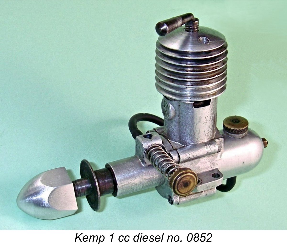
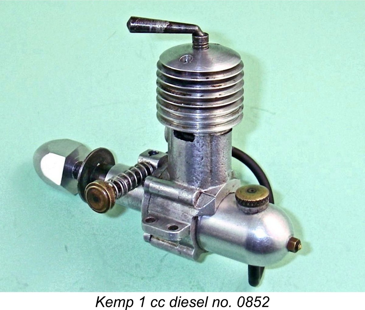
At the rear, the nicely made fuel tank was retained by a brass stud and nut which engaged with a tapped central hole in the integral backplate. The earlier tanks were made of magnesium alloy, while the later examples were of aluminium alloy. The brass filler cap was of the snap-in variety, having a segmented spigot which compresses to allow the cap to be fitted into its retaining ring. A neat brass fuel supply spigot at the bottom completes the component. Like all of Harold Kemp's products, the quality of construction of my example of this engine is beyond reproach. It may look a little unimpressive on the outside, but inside where it counts there's nothing at all about which to complain. All fits remain absolutely first class despite the considerable use which this example has clearly received. Now, having described the engine in sufficient detail, it’s time to find out how it runs! The Kemp 1 cc Diesel on Test My illustrated example of the original Kemp 1 cc model bears the serial number 0852, which incidentally is the highest serial number of my personal acquaintance for one of these engines. It has clearly seen considerable use, but remains in perfect mechanical condition in all respects. Despite the changes to the needle valve control, the needle itself appears to be original. Consequently, those control changes would have no bearing upon the results obtained.
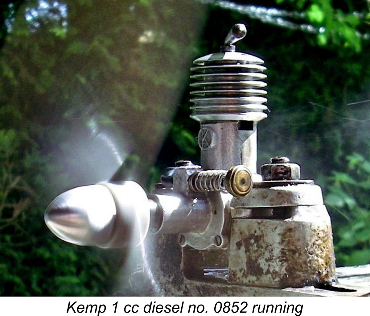
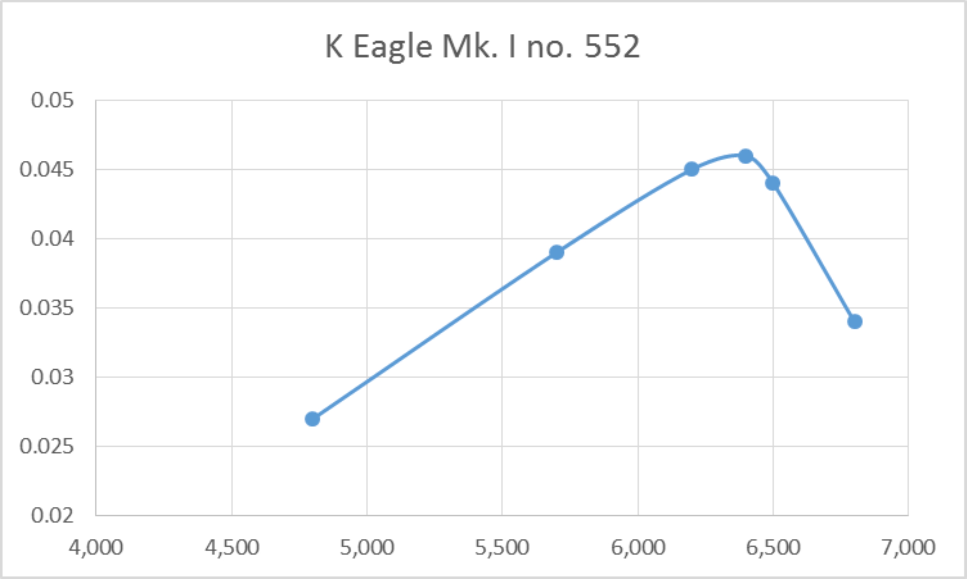
I began with an APC 8x6, which I felt would probably be the largest load that this engine would comfortably accommodate. This proved to be a good guess! The initial start turned out to be a bit of a chore – a lot of flicking with essentially no results. No doubt the presence of a considerable amount of storage oil contributed to this. Once the engine eventually began to come to life, I quickly learned that it was unusually sensitive to the amount of fuel in the cylinder - either too much fuel or too little, and it wouldn’t even fire. The amount of fuel required wasn’t large, but it had to be somewhere near right. The important thing turned out to be to avoid getting too much fuel into the crankcase during starting. If that happened, the engine would bog down and either oscillate or stop altogether. I found the best approach to be a single choked flick to fill the fuel line followed by a “dry” prime with the exhaust port closed. This generally produced a start in very short order. Even so, I would not classify this engine as an easy starter – while it's straightforward enough once you have the required approach down pat, getting to that point does take a bit of knowing along with some experience. Once running, things improved a lot. The engine was extremely responsive to the controls without either the compression or needle setting being unduly critical. Both controls held their settings perfectly. Running was quite smooth, although there was the occasional misfire which couldn’t be completely eliminated. Perhaps this was related to the marginal suction predicted by Maris Dislers’ calculator, as reported earlier. I have to say that the results achieved fell somewhat short of expectations. The following prop/rpm figures were recorded.
These figures imply a peak output of around 0.028 BHP @ 6,200 rpm, with an unusually sharp drop-off thereafter. The engine appeared to be extremely reluctant to operate above 6,500 rpm. By no means a stellar performance, although we must remember that this unit was designed during the previously-noted period when British designers were just cutting their teeth in terms of diesel design. Moreover, the Kemp 1 cc diesel was one of the first models of that displacement to enter production in Britain, if not the first. It’s always the pioneers who make the mistakes from which they and others learn! On the plus side, the engine showed itself to be a very well-made and sturdy unit which should give many hours of good service. With an 8x4 airscrew fitted, it would have had plenty of power to fly a free-flight sport model, although a control line application might be asking a little too much of it. I’m sure that a good number of these engines gave full satisfaction to their owners once the trick of starting them was mastered! The Next Step - the Kemp (later K) Eagle Mk. I
Despite its relatively high price, it would appear that Harold Kemp had succeeded in making and selling a fair number of these models up to early 1948. The lowest serial number of which I'm aware is 030, while the highest such number is found on my own engine no. 0852. This implies that the numbering sequence started at 001 and that perhaps as many as 900 examples were made in total - around 90 units per month. Not a bad record for a small 3½ man company that was also producing the Kemp K4 and (as of late 1947) the 0.2 cc Kemp Hawk. However, by early 1948 it was obvious that if Kemp was to remain in the 1 cc market, a new model having a better performance coupled with a lower price and less weight would have to be developed. Such a replacement design duly appeared in March 1948 in the form of the Mk. I version of the Kemp Eagle, which continued the company's "bird of prey" nomenclature which had begun in late 1947 with the 0.2 cc Hawk. The company's newly-adopted "K in a circle" trademark was also featured on the crankcase casting. The new model was priced at a somewhat more competitive but still relatively high £3 18s 6d. (£3.92). it also weighed in at a far lighter 63 gm (2.22 ounces). Thus it achieved at least two of its design objectives right off the shelf. The performance criterion will be tested in a following section of this article.
This was a rare instance in which a manufacturer who had previously been employing FRV induction switched back to the old tried and tested sideport system. In this case, however, it must be recalled that the original FRV 1 cc design had not proved to be a stellar performer. Harold Kemp decided to try what could be done with a radically redesigned engine using sideport induction allied to the emerging “high performance” diesel technology of 360 degree radial porting. At the time of writing, this was the only example of which I was aware of an engine of this period which combined these two features. Kemp also switched to short-stroke internal geometry when planning this model. The Eagle featured bore and stroke measurements of 0.437 in. (11.10 mm) and 0.400 in. (10.16 mm) respectively for a displacement of 0.98 cc. The idea here was presumably to keep the overall height down - the long-stroke sideport designs of the day tended to be taller than ideal for mounting purposes, particularly when cowling was involved. The design certainly achieved this objective, although the rather cumbersome oversized fuel tank spoiled the effect to some degree.
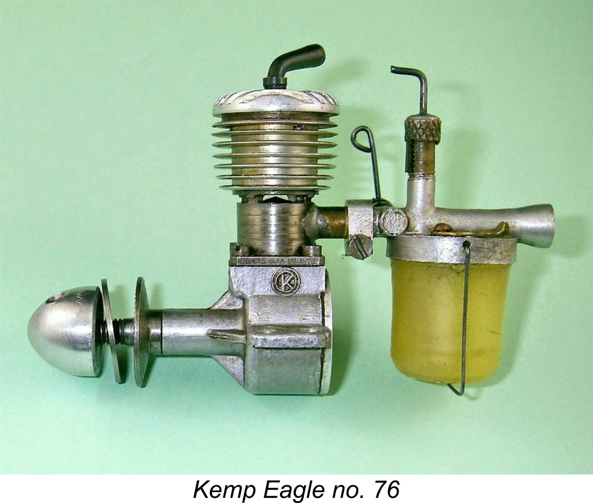
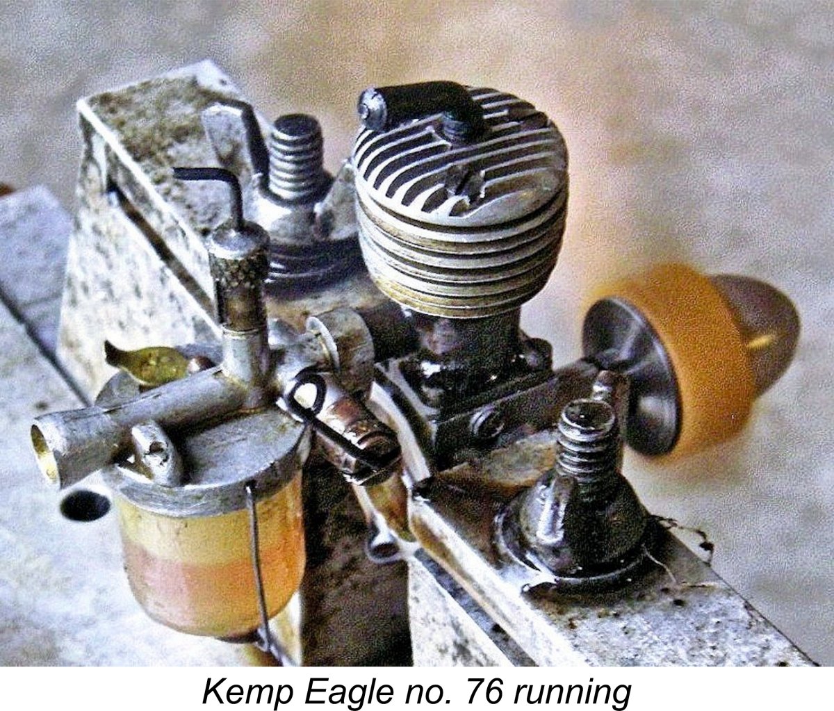
The Eagle also broke with British design tradition by using a hardened steel piston in conjunction with a ball and socket arrangement for the little end of the hardened steel con-rod. The use of this material for a piston operating in a hardened steel cylinder placed a premium upon manufacturing fits, since a steel-in-steel combination has a far greater tendency to tighten up when hot than the more common iron-and-steel setup. Moreover, an engine built to this material specification would take forever to free up if assembled too tightly. My own engine number 76 suffers to a degree from this issue, being perhaps a little more closely fitted than ideal. Although it starts and runs just fine, it does tend to run "tight" and sag if pushed hard on a lean mixture. My other example number 522 is perfectly fitted.
Internally, the little Eagle contained a couple of surprises of the "......why on earth did he do that!" variety. The accompanying component view kindly provided by Eric Offen should help to clarify some of these points.
The next major oddity is the method of assembling the upper cylinder components. The upper cylinder liner was externally threaded to accept a screw-on cooling jacket which seated on a location flange just above the exhaust ports. On the early examples this was followed by a steel ring which was secured to the cylinder liner by being internally threaded like the cooling jacket. This steel ring had to be well secured to the liner because it's the threaded holes in this component alone which hold the cylinder head in place - the threads for the head retaining screws do not extend into the cooling jacket itself on these early examples.The ring screwed onto the same threads as the jacket and acted in effect as a lock-nut to keep the jacket from unscrewing. I've never cared to disturb my near-mint early example number 76 to find out. Once this assembly was complete and tightened down really hard, the three holes for the cylinder head attachment were evidently drilled and tapped in their correct locations to keep the finned cylinder head in a fore-and-aft orientation. The fact that this was done with the ring in place is seemingly proved by the fact that the holes for the tapped threads extend into the material of the cooling jacket, although the screws themselves do not do so. The lock-nut effect would keep the jacket from becoming loose and upsetting the head alignment. A nice touch was the inclusion in the head of a threaded insert for the single-armed steel compression screw.
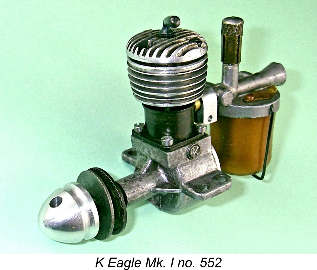
On the later versions as exemplified by illustrated engine number 552, the uppermost groove was machined out to a far lesser depth in order to create sufficient thickness for a reasonable thread length within the jacket itself, together with the use of longer assembly screws. The steel ring now served as a spacer rather than as the sole means of retaining the head. Its retention was only necessary in order to preserve the engine's overall geometry and perhaps to continue to serve its "lock nut" function. The drilling and tapping of the holes in the jacket for the head retention screws was presumably carried out as before after tightening. This arrangement appears at the right in the above illustration.
Another oddity is the seemingly excessive size of the mounting holes in the beam mount lugs. I once thought that my own two examples had both been drilled out, but other surviving examples consistently exhibit the same feature. They surely can't all have been drilled out, so I now assume that the holes were drilled to this size during manufacture. Presumably the idea was to leave some latitude for the owner to vary the side-thrust during the model trimming procedure. Either that, or Harold Kemp anticipated the use of extremely sturdy mounting bolts for these engines! Looking now at the fuel supply arrangements, the tank and needle valve assemblies were completely conventional for the period in question apart from the size of the tank, which appeared quite excessive for an engine of this displacement. The brass inlet boss at the rear of the cylinder accommodated the delivery end of the venturi, which plugged into it. The boss was split, allowing the venturi to be secured in any desired orientation using a split collar.
The venturi, cut-off housing, needle mounting and tank top were cast as a single component. The needle valve was of the surface jet type, a very common arrangement at the time. The cut-off incorporated into the system was relatively complex but quite effective, being of the spring loaded plunger type which completely blocked the venturi tube at its delivery end when activated. A necessary feature, since the little engine seems able to run forever on the contents of its massive tank! Once again, one wonders why the tank was so large - it looks ill-proportioned, positively dominating the rest of the engine.
My engine number 76 seems to prove that the numbering sequence was re-started at engine number 1 when the sideport Eagle replaced the original FRV Kemp 1 cc model. Production of the Mk. I Eagle evidently continued for a time after the K Model Engineering Co. Ltd. took over the business in mid 1948, since the engine continued to be featured in the early advertisements placed by the new company. The highest presently-reported serial number for the sideport Eagle is the late Paul Rossiter's engine number 852, indicating that perhaps 900 or so examples may have been produced in total over a period of some 6 or 7 months. Fair enough - so the new design was lighter than its predecessor, also selling for a lower price. However, the asking price was still quite substantial for an engine of this displacement. Did it have the improved performance which alone could justify such a price? Let’s find out! The Kemp (later K) Eagle Mk. I on Test I had already conducted a test of K Eagle Mk. I no. 76 some years ago in connection with my previous article on MEN. The data remained available for reference in the present instance. I had also kept full notes of the engine’s behaviour. Those notes show that I found the little Eagle to be a very easy starter provided a port prime was administered as a preliminary. Once running, the engine performed very steadily without missing a beat. The tank appeared to be rather oversized for the engine, and indeed it provided a very long run - free flight users would have to make other arrangements or monitor the fuel level in the tank at launch very carefully.
I’ve refined my power absorption coefficients somewhat since the original test and have added a few more props to my calibrated set. This being the case, I repeated the earlier test, this time using sister engine no. 552. As noted above, this example feels slightly better fitted than no. 76. The fuel used was a 35/35/30 mix of ether, kerosene and castor oil. Set up in the test stand, the engine proved to be just as easy to start as its previously-tested companion no. 76. It liked a couple of choked flicks followed by a small prime, after which starting was almost immediate with very little flicking. It showed itself to be very responsive to the controls, hence being very easy to set for best performance. Once set, it ran very well indeed. I'd actually rate it as a more user-friendly engine than its Kemp 1 cc predecessor. A few checks on the cutout function showed that this device worked perfectly every time. "Aeromodeller" tester Lawrence Sparey had endless trouble getting cut-outs to work properly, but even he should have been able to get this one to function! I selected my range of test props using the data obtained earlier for engine no. 76 as a guide. The following data were recorded on test.
As can be seen, the Eagle Mk. I evidently developed around 0.046 BHP @ 6,400 rpm, pretty much as reported previously for engine no. 76. In typical sideport fashion, the power drops off sharply once the peak is passed. There would be nothing to be gained by operating this engine in the air at speeds over 6,500 rpm. A 9x5 would appear to be a very good match for the engine. These figures represent a very substantial improvement in performance over the former Kemp 1 cc FRV model. The peaking speed is very little changed, but torque development is clearly much improved. In addition, I would objectively rate the Eagle's general handling characteristics as superior. I see it as a definite step forward despite the seemingly regressive move from FRV back to sideport induction. This notable improvement in performance was undoubtedly due to Harold Kemp’s very clever application of 360 degree radial porting to a sideport design coupled with the switch to short-stroke internal geometry. Even so, the Eagle was quickly rendered uncompetitive both in price and performance terms by such 1 cc competitors as the FROG 100 Mk. II and the E.D. Bee, to say nothing of the Mills .75. It was inevitable that work would eventually be put in hand to develop a further upgraded replacement. The Final Model - the K Eagle Mk. II
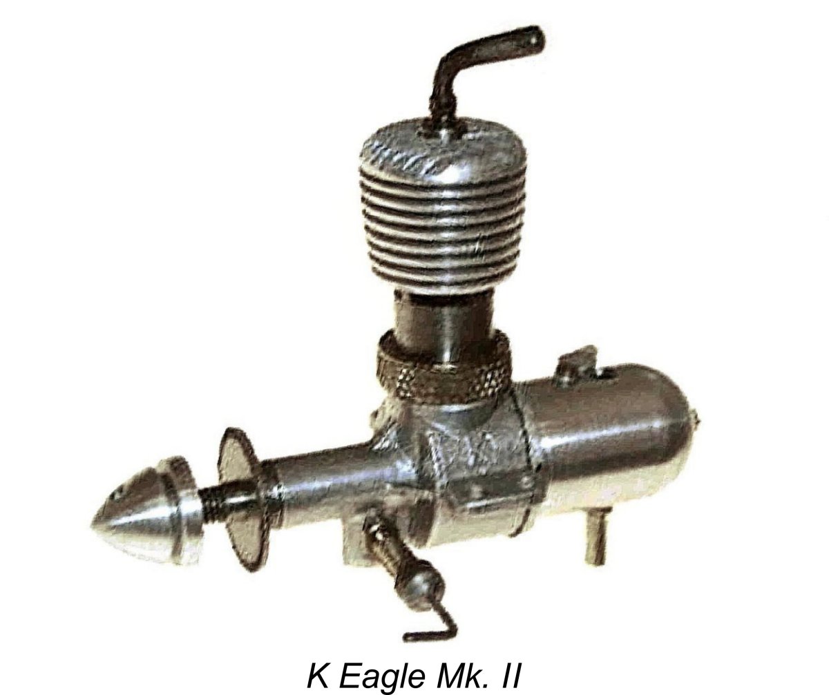
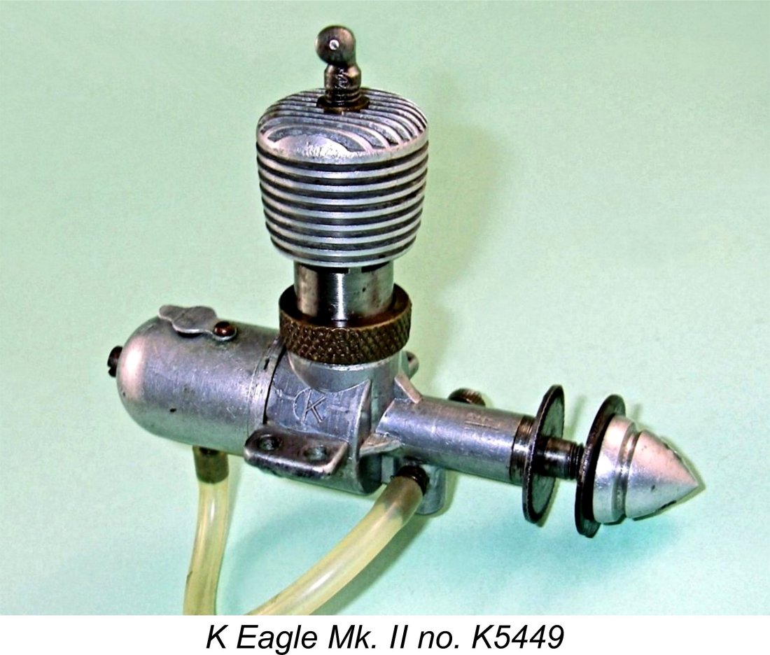
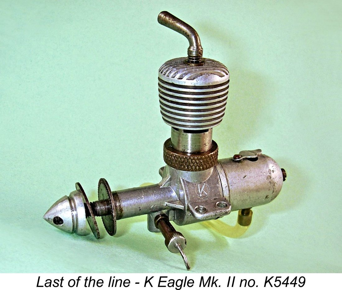
Steward’s first FRV design was the 5 cc K Vulture, about which I’ve written in detail elsewhere. However, it didn’t take him long thereafter to come up with an FRV replacement for the sideport Eagle Mk. I. By October 1948 production of the Eagle Mk. I had evidently ceased, with remaining stocks of that model being sold off at a greatly reduced price of only £1 17s 6d (£1.87 today). During this period Steward redesigned the Eagle from the ground up, resulting in the introduction of the FRV Eagle Mk. II in December 1948 in both ready-to-run and kit forms. This engine shared virtually no components with its predecessor, being essentially a completely new design to occupy the 1 cc slot in the K range, re-using the Eagle name solely for brand-name continuity. It featured updraft FRV induction, a screw-on turned aluminium cooling jacket and an aluminium alloy back tank.
Bore and stroke of the new model were unchanged from the Mk. I version at 0.4373 in. (11.11. mm) and 0.3975 in. (10.10 mm) for a calculated displacement of 0.979 cc (0.598 cuin.). The engine weighed 67 gm (2.36 ounces) complete with tank and fuel tubing. The revised model sold right from the outset at the rather startlingly low price of only £1 17s 6d (£1.87 today), thus undercutting all of the contemporary opposition by a considerable margin. This was actually the same price as that which had been applied to the Mk. I Eagle during the clearance of stocks of that model from October 1948 onwards. The Mk. II kit was even cheaper at only £1 7s 6d (£1.37). This kit included all major components fully machined and ready to assemble, including a factory-fitted piston/cylinder/contra piston set. The only custom fitting required from the constructor was the lapping of the crankshaft journal to fit the main bearing - the rest was simple assembly.
This being the case, it’s quite possible that the low price of the Eagle Mk. II right out of the starting gate represented an attempt to woo customers back to the range with a more dependable model which sold for more or less its manufacturing cost. In effect, its sale at the cited price may have been a customer relations gesture rather than being based on any rational return on investment. The introduction of this new design coincided with a change in marketing policy, with the K Model Engineering Co now offering a factory-direct sales service. This too may be a reflection of emerging The serial number sequence for the Mk II version of the Eagle appears to have been re-started at engine number 5001 with a K prefix added to distinguish it from other contemporary K models. My illustrated test example bears the serial number K5449, implying that at least 500 or so examples may have been manufactured. Nonetheless, this variant is extremely rare today, since it was only in production for some 5 months at most, likely at a fairly modest level. Its final appearance in a K Model Engineering Co advertisement came in April of 1949, albeit by that time in kit form only. It's not known how many examples were sold in kit form, but those that were presumably didn't receive serial numbers. OK, so the Eagle Mk. II represented a further price reduction in the K 1 cc series, also maintaining a very reasonable weight for its displacement. Next question - how did it do in the performance department? Let's find out the noisy way! The K Eagle Mk. II on Test My example of the K Eagle Mk. II bears the serial number K5449. It was formerly owned by my late and much-missed friend Paul Rossiter. Apart from having had its needle valve shortened by a previous owner, it remains in excellent original condition.
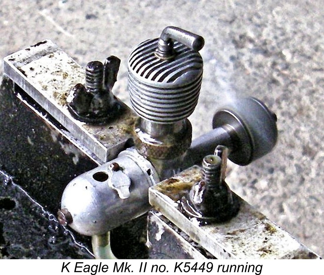
I elected to use the engine’s own back tank for this test. It proved to hold enough fuel for at least a 2-minute run, allowing plenty of time to optimize the settings and take speed readings on each prop. Anticipating somewhat higher speeds than with the Mk. I version, I used my standard nitrated classic diesel fuel containing 40% kerosene, 30% ether, 30% castor oil and 1.5% ignition improver added to the overall mix. I will admit for the record that the first start proved to be rather more challenging than I had expected. The problem was that the engine exhibited rather poor fuel draw on starting, even though the tank elevation was such that gravity feed was assured. In order to get it to pick up dependably on a firing burst, the needle had to be withdrawn by half a turn or more. Once running, it could be re-set to its best running position more or less immediately. It turned out that a prime was pretty much essential for starting. Any fuel drawn into the updraft intake simply dripped out onto the ground! It was best to ensure that the fuel line was full and then prime the exhaust ports. I also found by experience that the engine liked to be started with the compression setting reduced by up to a quarter turn.
One running, it was necessary to pick up the compression setting from the initial firing burst. After getting the compression to where it needed to be, all that was required was to adjust the needle. This proved to be quite straightforward since needle response was well defined without being ultra-sensitive. If leaned out past the sweet spot, a crackling misfire would develop, but the engine would slow down very little if at all. All that was then required was to richen the mixture slightly until the crackle just disappeared. Thereafter, the engine would run the tank out as smoothly as one could desire. There was no tendency to sag at any time, indicating a perfect piston/cylinder fit. I started the test using an 8x4 APC airscrew, which was one of the faster props used in the previous test of the Eagle Mk. I. As noted earlier, I was expecting the Eagle Mk. II to develop its peak power at a higher speed than the Mk. I, with lower torque development at the bottom end. That’s exactly what I got. The Mk. II could only manage 5,900 rpm on this prop, which the Mk. I had turned at 6,800 rpm. What was going on?!? It turned out that the answer to this question lay in the Mk. II's very different torque characteristics. Low end torque was markedly inferior to that of the Mk. I, but torque was far better sustained as speeds rose. Consequently, on the 8x4 prop the Mk. I had already passed its peak and was on the way down the higher-speed end of its power curve, while the output of the Mk. II was very much still on the way up with rising speed. It was obvious that the trick with the Mk. II would be to go for progressively lighter loads to allow it to reach what was evidently a substantially higher peaking speed. This proved to be exactly the right way to proceed. The following data were recorded.
As can be seen, the Eagle Mk. II turned out to develop a peak output of around 0.046 BHP @ 9,300 rpm. Exactly the same output as the Mk. I, but delivered at a far higher peaking speed. This would certainly improve the engine’s chances of hauling a control line model around at a somewhat higher airspeed - one could use a lower-pitch prop and still achieve better airspeed. A 7x5 prop would probably suit it nicely for control line, with a fast 8x3 for free flight. Unfortunately, for all its worthy qualities the K Eagle Mk. II only survived in the marketplace for some 5 months. As previously mentioned, serial number data suggests that no more than 500 or so examples were produced during that period. The engine is relatively seldom encountered today.
Whatever the reason, the withdrawal of the K Eagle Mk. II in May of 1949 marked the end of the K Model Engineering Company's efforts to establish a foothold in the 1 cc market category. Sadly, the consumer relations troubles which had begun with the Mk. I Vulture did not resolve themselves in time to allow the company to reclaim its position in the marketplace, the result being that production of all models had most likely ceased as of early 1950. The company continued to advertise throughout 1950, although this almost certainly represented an attempt to recover capital by liquidating existing New Old Stock. The final advertisement of them all appeared in the November 1950 issue of "Aeromodeller". A sad end to a venture which had started with so much optimism and promise back in 1946 and had produced a number of noteworthy model engine designs along the way. The end of the K Model Engineering Co. was very far from the end of Len Steward's involvement with model engines. He went on to work with his close friend Dennis Allen, first with the Aeronautical Electronic & Engineering Co. during the period of their manufacture of the AMCO 3.5 engines and then with the development and manufacture of Allen's own Allen-Mercury (A-M) range. He was still active in the late 1960's, offering a highly-regarded reboring service on his own account. Summary and Conclusion
The original Kemp 1 cc diesel was a very worthy effort by a fledgling designer/manufacturer who was still very much “learning the ropes” at the time of its introduction. Being among the first British entries into the 1 cc field, the engine undoubtedly attracted considerable buyer attention and doubtless served many of its users well. However, for the same reason it also fell somewhat short in the design department. It’s greatly to Harry Kemp’s credit that he recognized the limitations of this model as quickly as he did and moved so creatively to come up with a suitable replacement in the shape of the Mk. I Eagle with its unique combination of sideport induction allied to radial porting and short-stroke working geometry. This was an excellent design which was continued for a time by the successor K Model Engineering Co. before being replaced in turn by a completely revised Eagle Mk. II model which reflected the new company's emerging policy of producing FRV diesels featuring their distinctive "dog collar" cylinder assembly. There is a certain consistency in the production figures noted above. It seems that production of the Kemp and K 1 cc models remained fairly steady at around 100 units per month throughout the company's involvement with that displacement category. Other models were produced at substantially higher rates, especially after the K Model Engineering Co. took over. This makes it appear probable that their involvement with the 1 cc category was perhaps the company's least successful business line in commercial terms. Regardless, I hope that you’ve enjoyed this look at another series of pioneering products from what was to become Britain’s world-leading model diesel manufacturing industry during the “classic” era! It was from engines such as these that Britain’s model engine designers learned their most important lessons ….… and learned well! __________________________ Article © Adrian C. Duncan, Coquitlam, British Columbia, Canada First published September 2018 Tests of Eagle Mk. I and Eagle Mk. II added August 2020.
|
||
 This article began life in September 2018 as the first-ever published test of an almost-forgotten British 1 cc diesel from the post-WW2 pioneering era of well over 70 years ago now – the original 1947 Kemp 1 cc model from Gravesend in Kent, England. This neat little unit was among the first products of the
 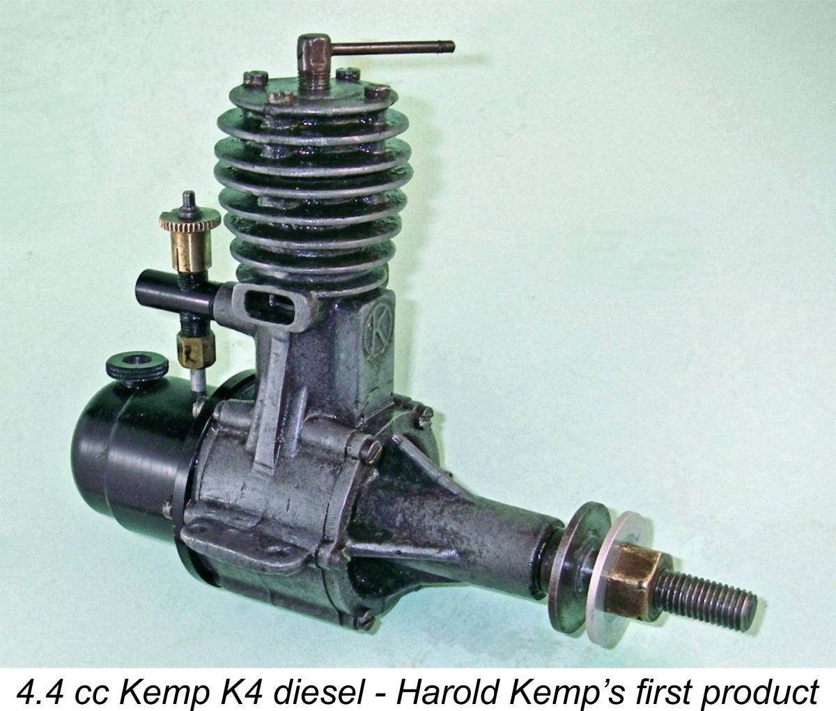 Whether or not Kemp designed and perhaps manufactured the K6, there’s no doubt at all that the first model engine to be marketed under his own name was the
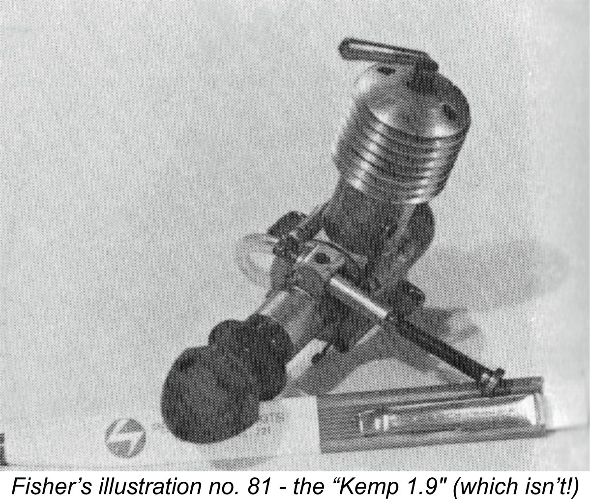
 It took some time for British constructors to get to the point at which they were ready to release their first commercial designs. The first commercially-advertised British diesel was the
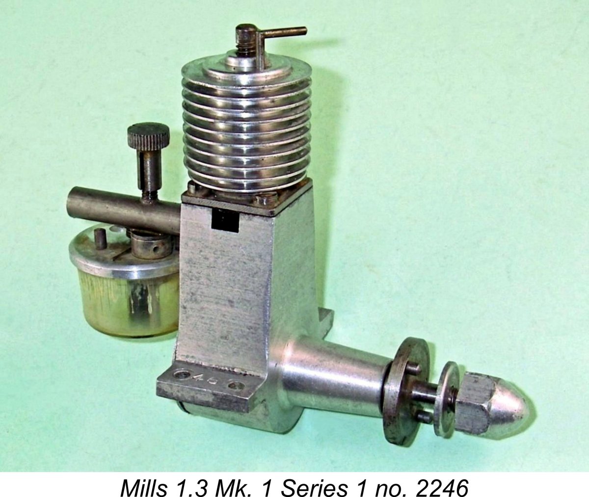
 The 1947 Kemp 1 cc diesel was a basically conventional crankshaft front rotary valve (FRV) long-stroke diesel. It was produced during the era in which British precision engineers preferred to work in fractions of an inch rather than their decimal equivalents. This is really odd considering the fact that these same individuals invariably expressed their engines' displacements in cc! Regardless, the nominal bore and stroke dimensions of the little Kemp were
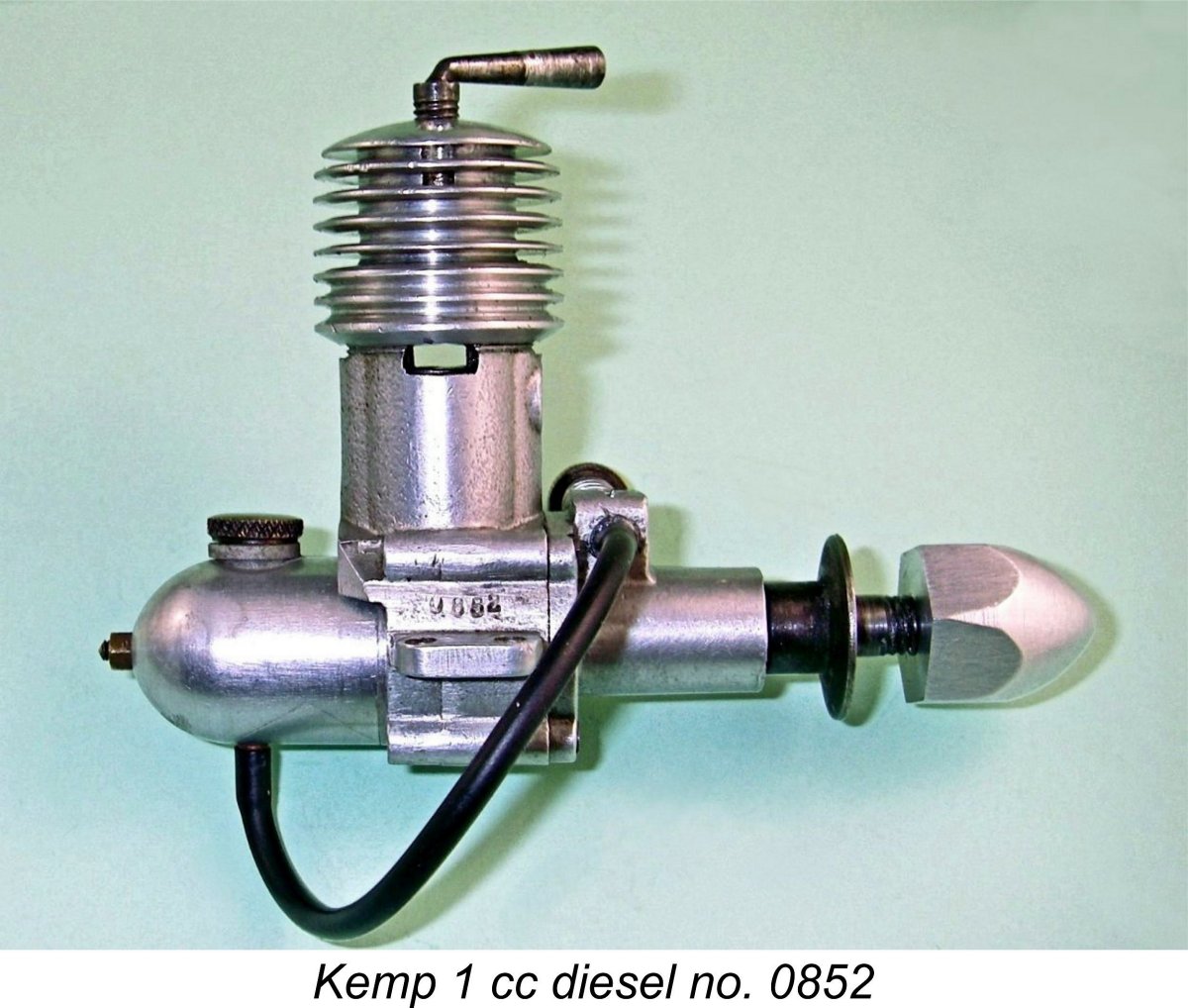 The lower cylinder was a drop-in fit in the upper crankcase casting. The cylinder was vertically located by a flange machined onto its outer surface a little way above the exhaust ports. This bore upon the upper surface of the crankcase casting, the joint being sealed with a paper gasket. The screw-on cooling jacket was provided with an internal shelf which bore upon the upper surface of the cylinder flange, securing it in place. This was a good arrangement in that it eliminated any assembly stresses which might cause distortion of the cylinder bore. The same system was later used by Mills Brothers in their
 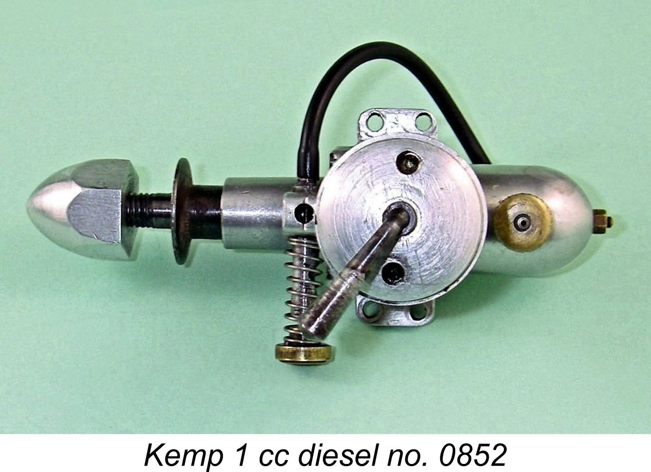 A notable feature of the front housing is the seemingly minute size of the intake. This has an internal diameter of only 0.125 in. (3.175 mm). A surface jet needle valve system is employed, meaning that the only component traversing the venturi throat is the tapered end of the needle. Estimating the average diameter of that tapered section in running position as around 1 mm, reference to Maris Dislers’ invaluable
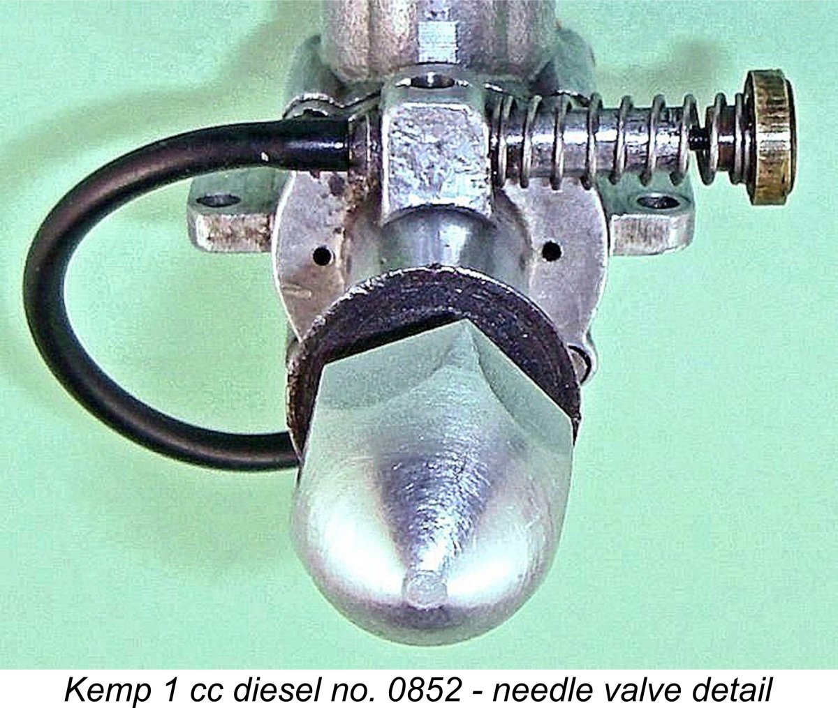
 I elected to use the standard back tank for all the test runs. I actually like testing engines which have their own built-in tanks – there’s a satisfying sense of self-contained compactness in operating in this manner.
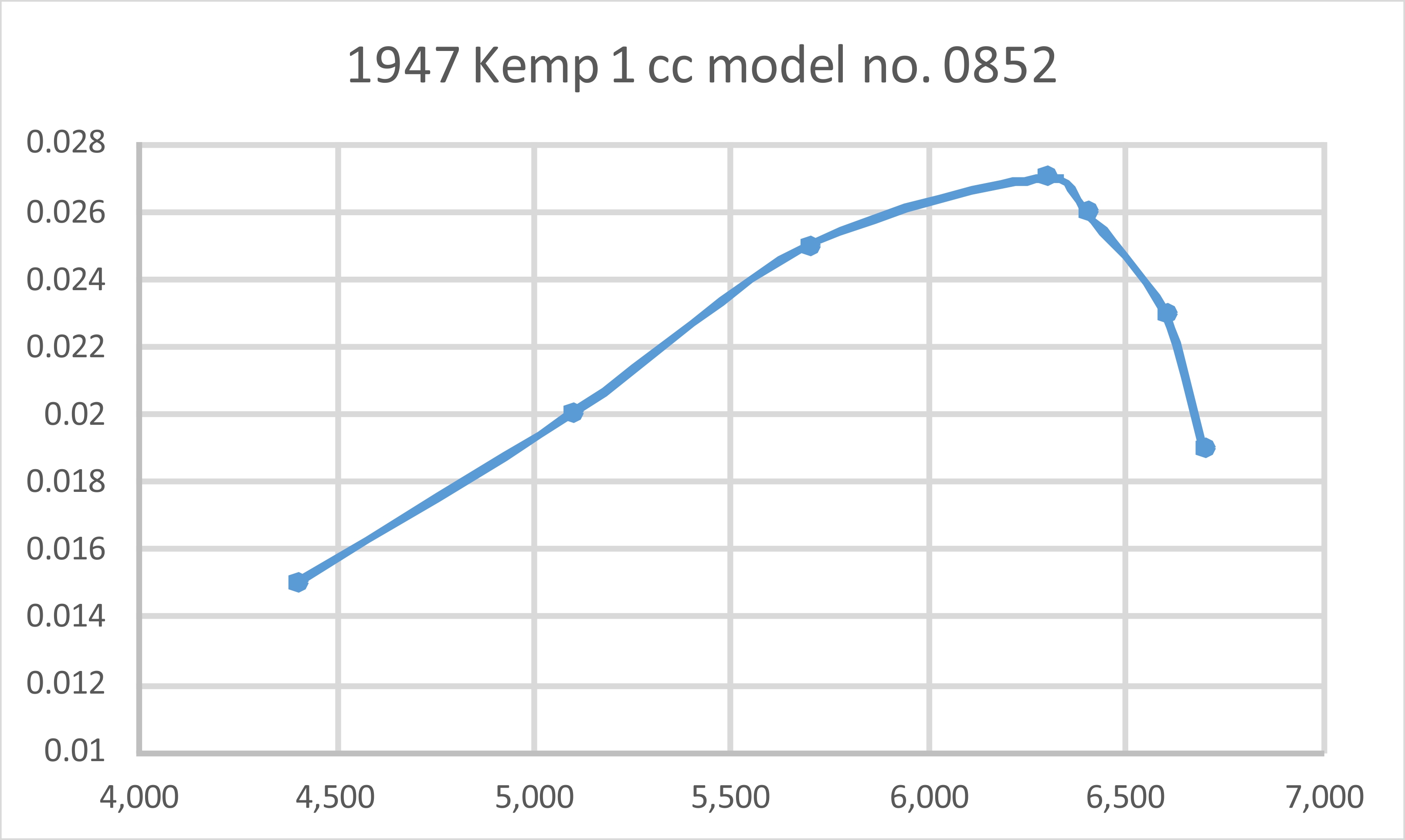
 The Eagle was highly unusual among sideport designs in using four radially-disposed exhaust ports in combination with six transfer flutes cut internally into the lower cylinder wall and terminating just below the exhausts. These transfer flutes were arranged in an arc to either side of the rear-facing induction port - a scheme very similar to that later used in the home-constructed
 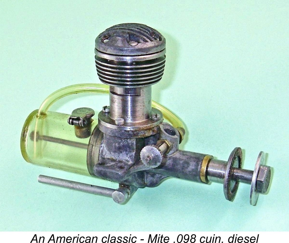 The use of a ball-and-socket small end bearing was by no means new - it had previously appeared in several American designs such as the
 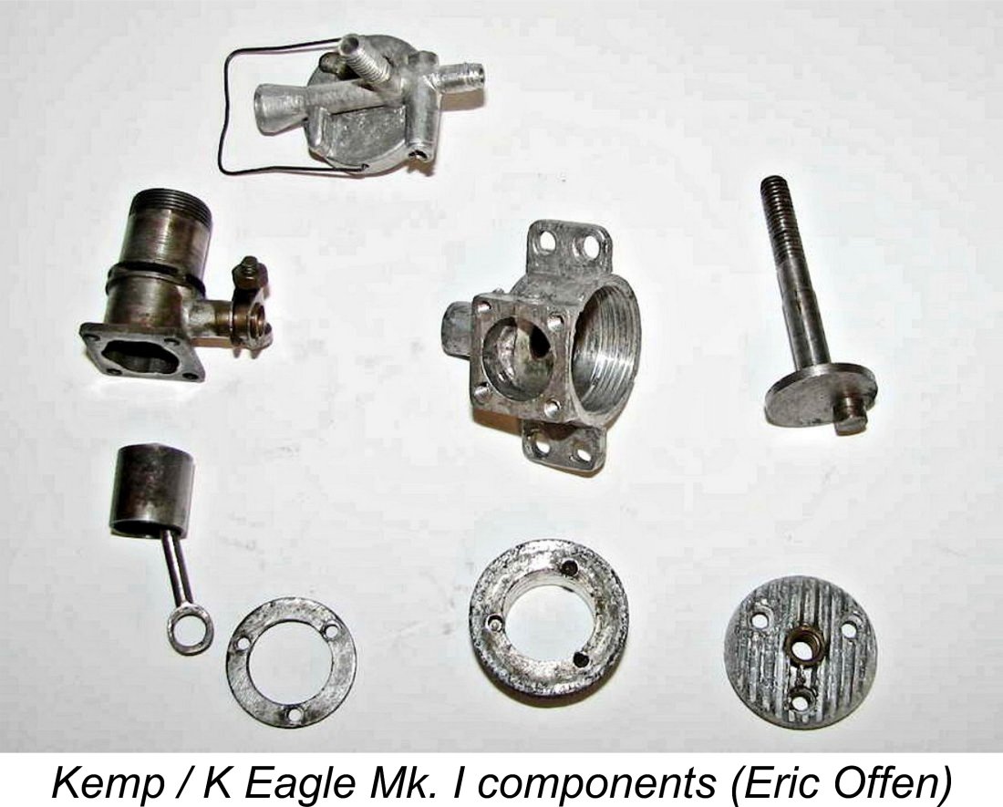 The steel piston and con-rod with ball and socket little end connection have already been mentioned. Next was the truly heroic crankpin diameter and associated con-rod big-end. The use of a hardened steel con-rod resulted in the creation of a "hard on hard" big end bearing. This is never a great idea, although it is perhaps acceptable on a low revving, well lubricated small diesel -
 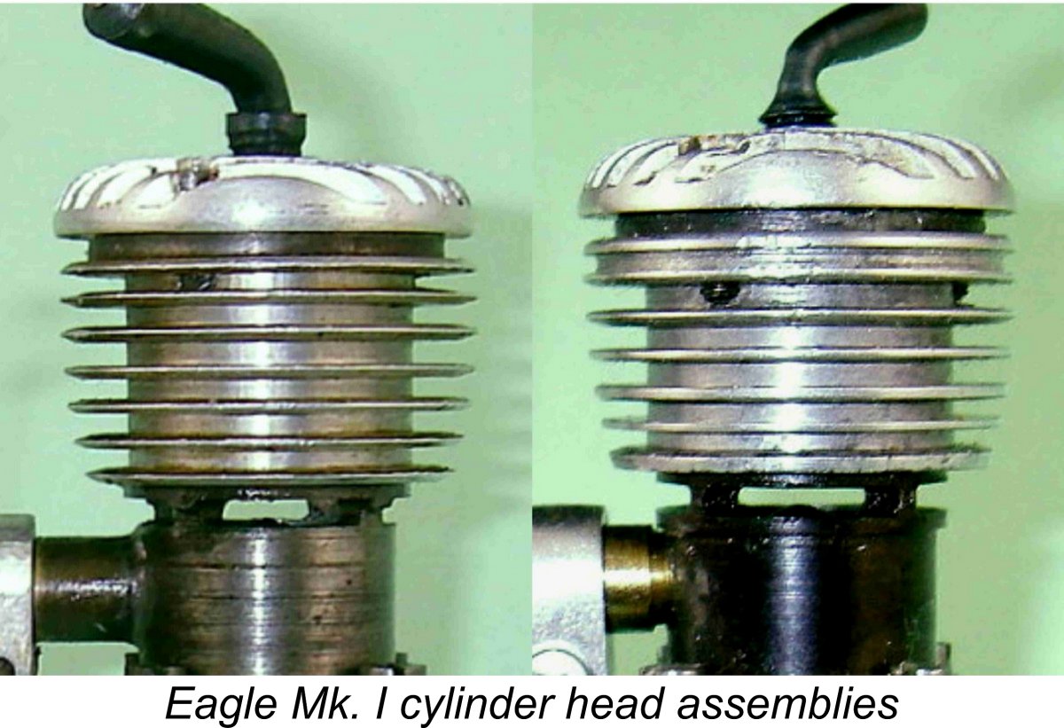 As mentioned above, the early examples relied solely upon the threads formed in the steel ring to retain the head, very short screws being employed. The six cooling grooves below the steel ring were accordingly machined out to full depth since the jacket did not have to accommodate any assembly threads for the head screws. Illustrated engine number 76 features this arrangement, which appears at the left in the accompanying illustration.
 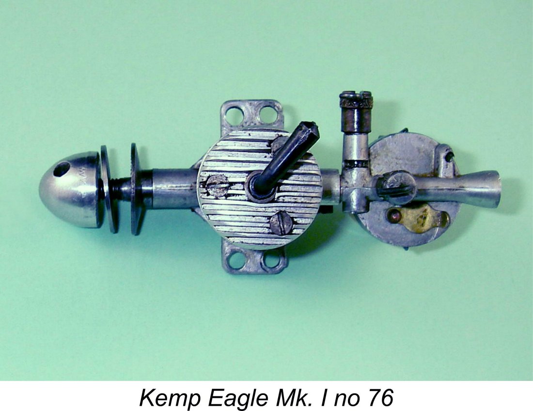 Why was this complicated assembly adopted? All that I can think of is that the original intent was to eliminate the need to rely upon tapped holes in the alloy cooling jacket for the head screws. The steel ring clearly offered a far better medium for the creation of those tapped holes. Why then did they switch to holes tapped within the cooling jacket for the later models? Beats me.........
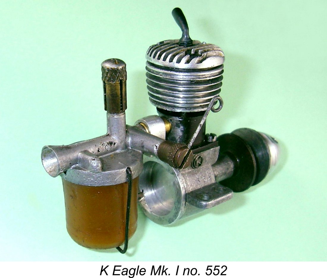
 In most respects, the new model followed the design pattern established by the Mk. I version of the 5 cc K Vu
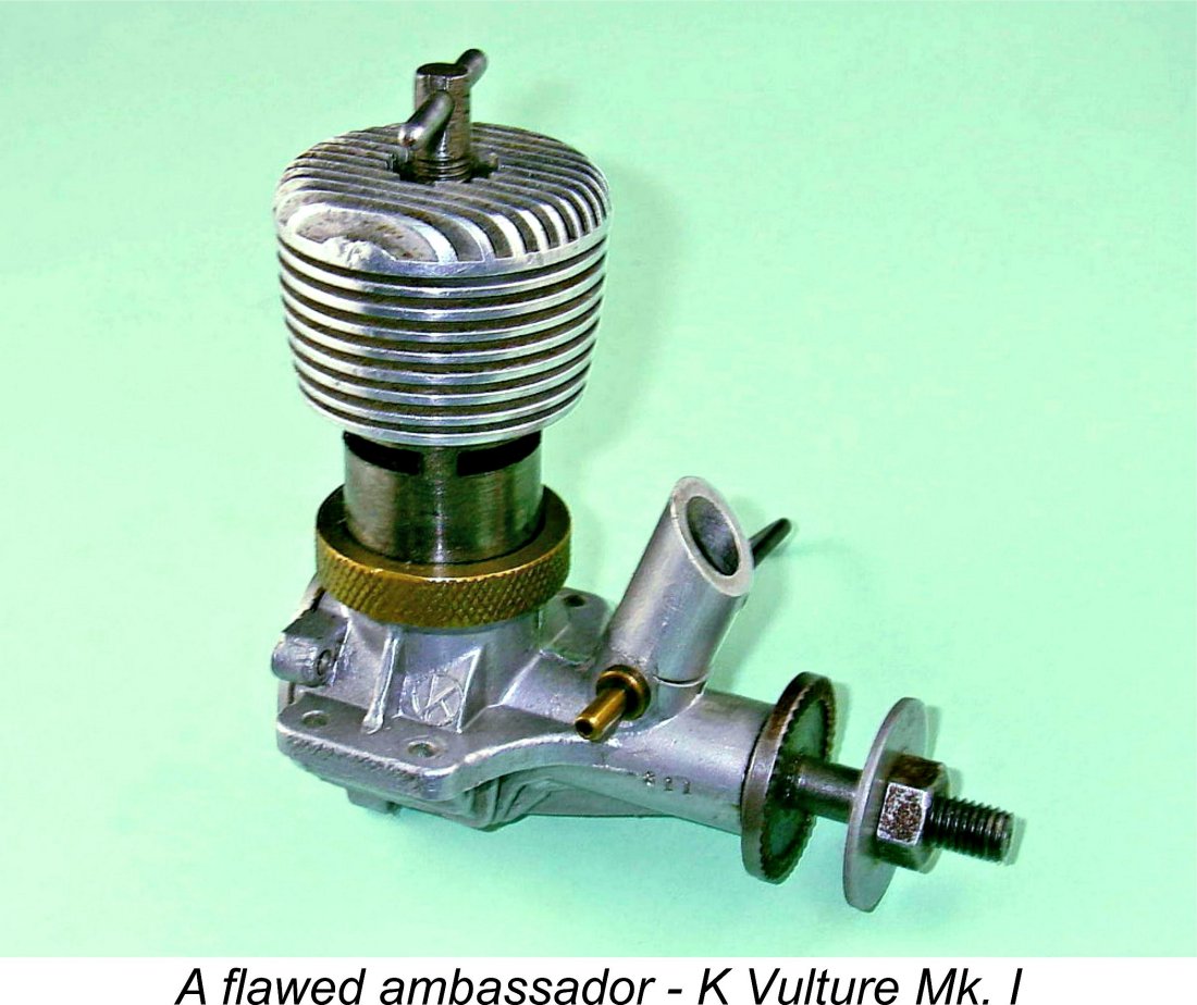 The possibility exists that the low introductory price of the Eagle Mk. II was driven as much by economic expediency as anything else - the original intent may have been to sell the engine at a somewhat more rational price. When the Eagle Mk. II appeared, the 5 cc
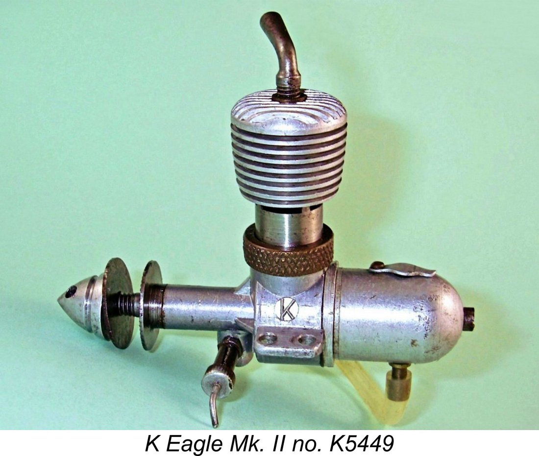
 Set up in the test stand, the engine felt really good. Compression was outstanding, while the main bearing was perfectly fitted. There was a little tightness at top dead centre, but nothing really to worry about. The ball-and-socket conrod small end bearing exhibited some detectable play, but this is an almost invariable feature of the K engines. It doesn’t affect running at all since the pressure on the bearing is always downwards in a low-speed diesel like this one.
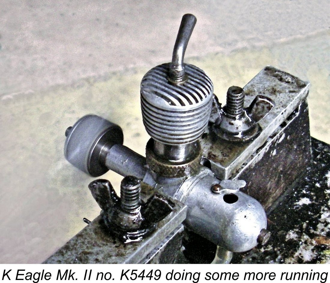 Once these requirements were recognized, I found the engine perfectly straightforward to start. However, the need to change control settings for starting makes this less than an ideal beginner’s engine. Simple enough for an old hand like me, but a rookie diesel user might have some difficulty. I'd objectively rate this engine's handling as slightly inferior to that of its Eagle Mk. I predecessor.
 The K Eagle Mk. II was most likely driven off the market by a combination of factors. One was undoubtedly the presence in the contemporary marketplace of competing and more widely-available 1 cc models offering equal or superior levels of performance at very little extra cost - the
 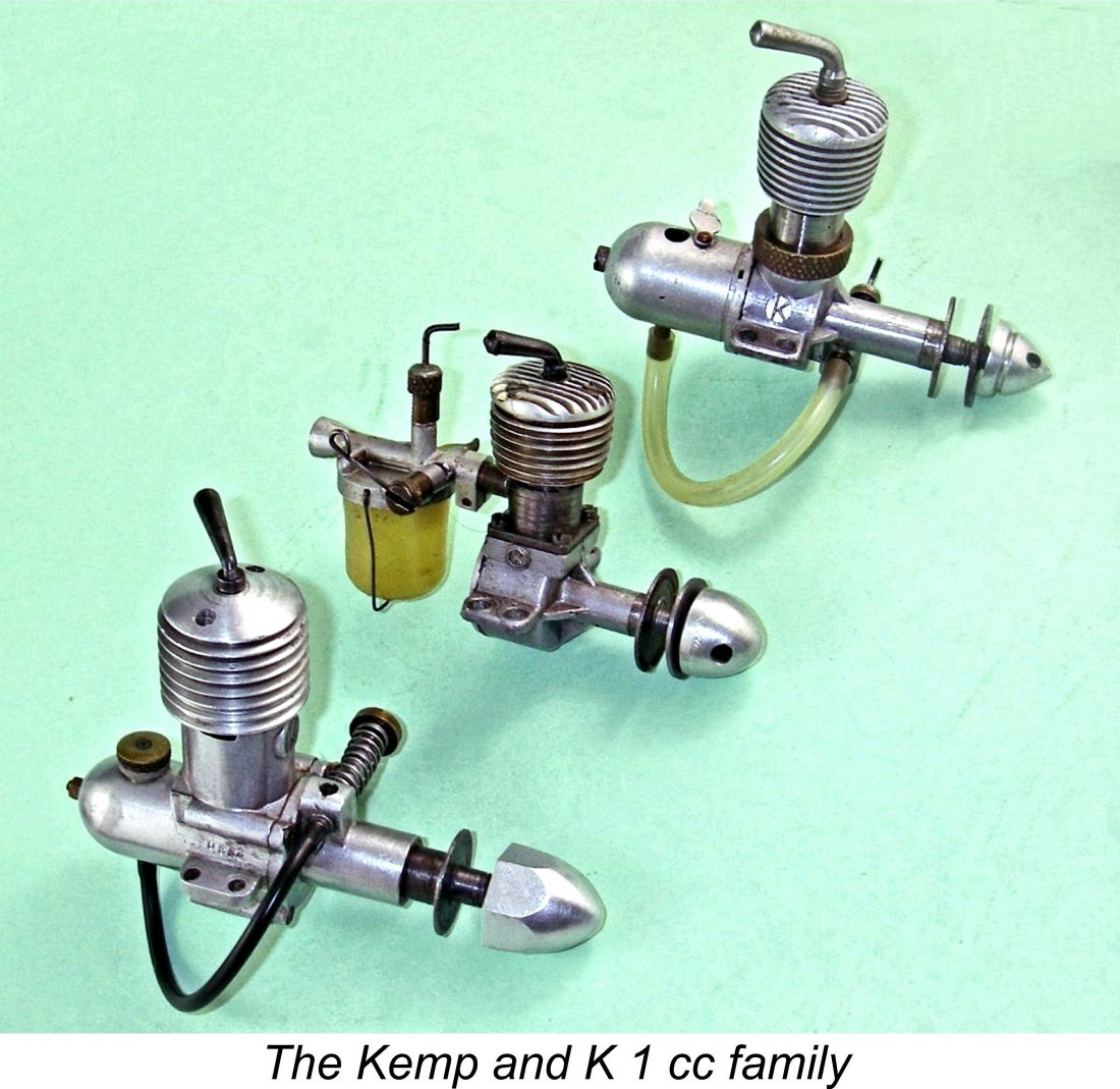 The series of 1 cc diesels produced by Kemp Engines and its successor company, the K Model Engineering Co., are rather unusual in displaying radical design changes with each new model. Single-displacement model engine design series from most manufacturers display steady improvement of a basic design, while each new model in the Kemp and K 1 cc series represented a total re-design which owed little or nothing to its predecessor.
 | |