
|
|
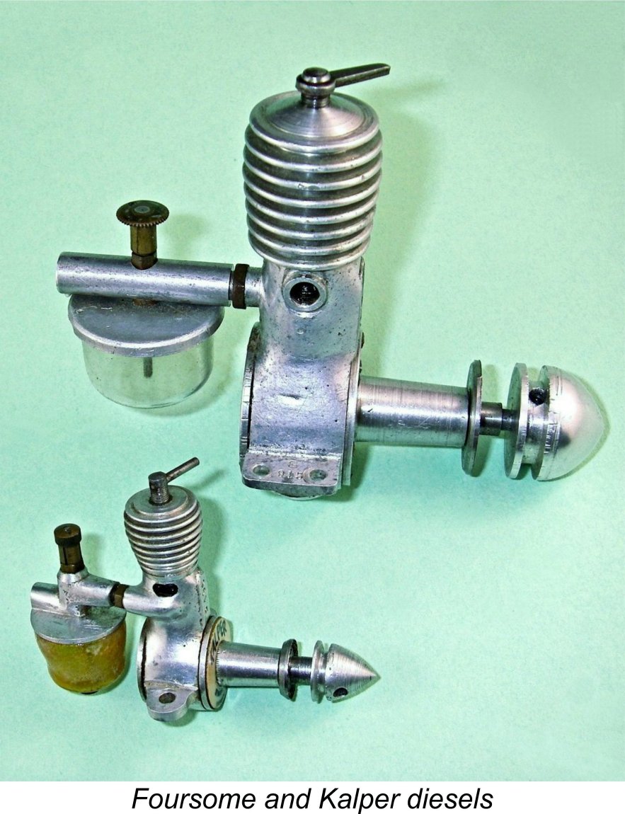
The Foursome and Kalper Diesels
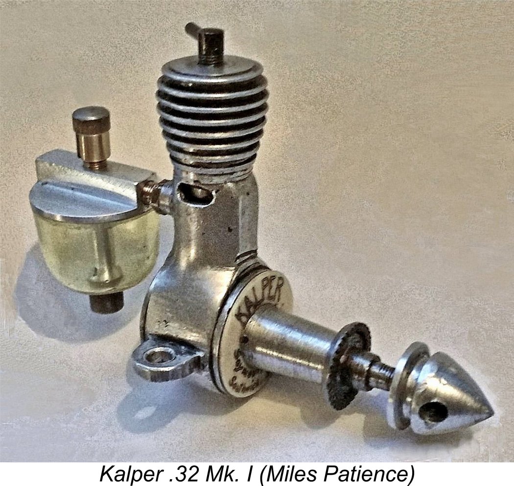
One look at the Foursome and Kalper .32 Mk. I is sufficient to suggest that they share a common design heritage. Closer inspection amply confirms the probable correctness of this view. It turns out that the link between the two models is a gentleman by the name of George Seymour, a resident of Southwick in Sussex. Located on the south coast of Sussex, Southwick is in effect a suburb of Brighton, lying a few miles to the west of the town centre. Most serious aficionados of early British model diesel engines have heard of the Kalper .32. Indeed, the engine was included in my own earlier article on the subject of the classic micro-diesels of the early post-WW2 period. However, the Foursome seems to be somewhat less well-known. In either case, relatively few people could rattle off the name of the manufacturer! In an earlier article dating back to July 2008 (when I was young!) which is still to be found on the late Ron Chernich’s now-frozen but still invaluable “Model Engine News” (MEN) website, I set down what was then known about these two engines. Since the publication of that earlier article, a considerable amount of additional information has emerged, greatly clarifying the history of these two units. In addition, I’ve now conducted full bench tests of both models. The additional information now available is more than sufficient to warrant the preparation of a comprehensively updated article. However, since MEN is now frozen as it was when Ron sadly left us in early 2014, I have no choice other than to present it on my own website. Before setting about this task, I must thank a number of individuals for making this update possible. My good friend Miles Patience has undertaken a considerable amount of research into the background of these two engines, while Peter Scott has provided a number of additional details. All of this has greatly enhanced my understanding of the story. Jan Huning performed an invaluable service by supplying detailed information on the construction of the Kalper .32. Eric Offen did likewise with the Foursome model. In addition, I’m greatly indebted as always to Maris Dislers for trolling his magazine collection for advertisements relating to the engines to be discussed here. Finally, Steve Hainsworth and Chris Murphy of New Zealand contributed images, serial numbers and test data. Without the help of these fellow enthusiasts, I couldn’t have written about these engines with any authority. It’s perhaps best to begin this comprehensively revised article by reviewing what we now know about the man who seems to have been their designer and (in my view) probable manufacturer - George Seymour. George Seymour, Master Modeller
During the 1930’s, Seymour became a well-known and highly respected member of the model engineering community in the south coast area of England. In 1937 he evidently decided to attempt to earn his living through his hobby, establishing a small precision engineering business called Seymour, Hylda & Co. The origin of the name Hylda seems very likely to have been a gender-neutralized reference to the name of Seymour’s wife Hilda, who also appears to have been an engineer given the inclusion of her name on a patent taken out by the company for a spring-loaded die. There were precedents - Jack Colyer used his wife’s initials as the first two letters of his Majesco trade name, for example.
The company’s main business prior to 1947 seems to have been the An intriguing aside whch may be interjected at this point is the existence of a number of alcoholic beverages of Spanish origin bearing the Kalper trade-name. Peter Scott provided images of the labels of such diverse offerings as blended whisky, gin and coffee-flavoured Orujo liquor all prominently displaying the Kalper name, while I have found other references by trolling the Internet. Very interesting, but I can't see how there could be any connection with George Seymour apart from the very vague possibility that some Kalper offering was his favourite tipple!
Seymour was one of a number of contemporary individuals who found himself greatly attracted to the challenge of creating small compression ignition engines. During 1947 he began to develop his own designs for such units. It’s pretty clear that from the outset commercial production was seen as the goal at which to aim.
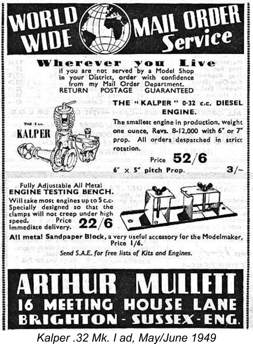
Arthur Mullett was an extremely interesting character with an unusual background. Fortuitously enough, his business was covered as the first installment of a new series entitled "Your Model Shop" which appeared in "Aeromodeller" magazine. This series focused upon a series of then-prominent model shops in Britain. The inaugural installment featuring Arthur Mullett appeared in the magazine's August 1951 issue. From this very informative article, which is reproduced below at the left, we learn that Arthur Mullett spent most of the two decades between the two World Wars working in the music business as a professional To supplement his income, Mullett also operated a musical instrument business in Brighton. In 1937 he added model aircraft supplies to his sales portfolio. This began as a sideline, but by 1939 it had become Mullett's main business activity. However, the onset of WW2 later during that year put the development of Mullett's business on hold. At the outbreak of the war, Mullett entered military service, setting his business interests aside for the duration. Following his demobilization in 1945, Mullett resumed his business activities, trading from premises at 16 Meeting House Lane in Brighton, where the business was to remain until 1962. Initially he returned to his musical roots, functioning once again as a musical instrument dealer, including overhaul and repair services for such instruments, while waiting for the model trade to regain momentum following the hiatus of WW2. This didn't take long! In 1947 Mullett judged that the domestic supply and demand picture for model goods had improved to the point where the British model trade had regained its economic viability. In consequence, he resumed his involvement with the model supply business at that point. By 1949 this side of the business appears to have taken over completely once more, with worldwide mail order becoming one of Mullett's main business strategies. Mullett’s late 1947 involvement with the marketing of the Foursome appears to have been one of his earliest post-WW2 ventures into the model goods distribution business. Interestingly enough, the advertisements attributed this engine to an entity named Foursome Products having its "head office" at the same address as Arthur Mullett’s shop - the name of Seymour, Hylda & Co. was never mentioned at any time in connection with the Foursome. However, it seems highly unlikely that the engines were actually manufactured at Mullett's retail premises. It is these facts which open the door to a degree of speculation regarding the manufacturer’s identity. While it’s true that the identity of the actual maker remains unconfirmed by separate evidence, there seems to me to be little doubt that the previously-mentioned "Model Engineer" obituary was correct in naming him as the designer. I can find absolutely no evidence to suggest otherwise. I also personally consider it to be far more likely than not that Seymour manufactured the Foursome - given his demonstrated talents, why would he design an engine for someone else to manufacture?!? The very clear “instrument-maker” stamp on the engine’s construction (see below) seems to me to be completely consistent with Seymour’s hands-on involvement.
At the time in the late 1970's when he passed these engines on to me, Laurie told me that he had purchased both of them over the counter at Arthur Mullett’s shop in 1949 and 1950 respectively (only some 28-29 years previously at the time). He saw no evidence of engine manufacture taking place at Mullett's retail premises on Meeting House Lane - rather, he claimed to have been told at first hand both by Arthur Mullett staff and others that both engines came from the same local manufacturer, Seymour, Hylda & Co. No advertising that Maris Dislers has been able to track down confirms this in the case of the Foursome, but none directly contradicts it either. I always found Laurie's recollections to be very accurate when they could be checked - at the time he was still only in his early sixties and his memories remained crystal-clear, as indeed they did lifelong. Issue settled, it would seem! However, there is one straw in the wind that might upset this apple cart. Many years ago now, an acquaintance of Miles Patience named Tony Grantham found 5 incomplete Foursome engines in various states of completion at the premises of an engineering company in Poynings, a small village lying some 5 miles north-west of Brighton. This location appears in the top portion of the previously-appended area map. The engineering company had changed hands some time before Tony’s visit, but had not then moved, although it did so later. It had been going since before the war, when it made wire products for Woolworths. During the war years, it produced munitions. After the war, it was listed as a “metal workshop”. There’s absolutely no direct evidence that the Foursome engines were manufactured by this Poynings company apart from the purely circumstantial fact that the chances of finding 5 incomplete surviving examples anywhere but at the manufacturer’s location do not appear to be high. That said, there are other possible explanations. For example, it could well be that George Seymour's son was involved with that firm and had brought those engines with him, intending to complete them himself using company equipment but never actually getting around to it. It's also quite possible that some employee of the Poynings company acquired the components from George Seymour's surviving wife and/or son. We'll probably never know exactly how these components ended up at Poynings ........................... There’s at least one more possible red herring to complicate this story. Eric Offen apparently recalled being told years ago by someone or other that the Foursome was made by a company located on Dyke Road in Brighton. Once again, there’s absolutely no supporting evidence whatsoever. Clearly, all these scenarios can't be right - take yer pick, mate! Since we’re dealing here with straws in the wind, we might as well get them all out in the open! There is one other line of inquiry which might possibly yield some further information if it could still be followed up after all the intervening years. In his late 1946 book “Model Diesels”, D. J. Laidlaw-Dickson mentioned that a Brighton firm known as Myers & Young of 46 Stanley Street, Queen's Park, Brighton, had announced plans to enter the model diesel engine field, although these plans had not then matured to the point where any of their products could be described. History tells us that Myers & Young never subsequently appeared on the record as model engine manufacturers at any time. It thus appears possible that Seymour, Hylda & Co. may have taken over Myers & Young's diesel development program. However, this is pure speculation which is included simply as a possible subject for further investigation. I personally believe it to be far more likely than not that Laurie Ellis’s recollections were accurate and that both the Foursome and Kalper were made by Seymour, Hylda & Co. in Southwick. The “Model Engineer” obituary openly credits the Foursome to George Seymour, and there's absolutely no separate evidence to contradict this attribution. The advertising trail does the same for the Kalper. Both the clear design relationship and the general style of workmanship strongly support this common origin. That said, I can’t claim the matter as proved beyond doubt, so we’ll just have to leave it there as a subject for further research if anyone cares to make the effort. Regardless of the true answer to the manufacturing question, let’s have a look at this most unusual engine. The Foursome Diesel - Description
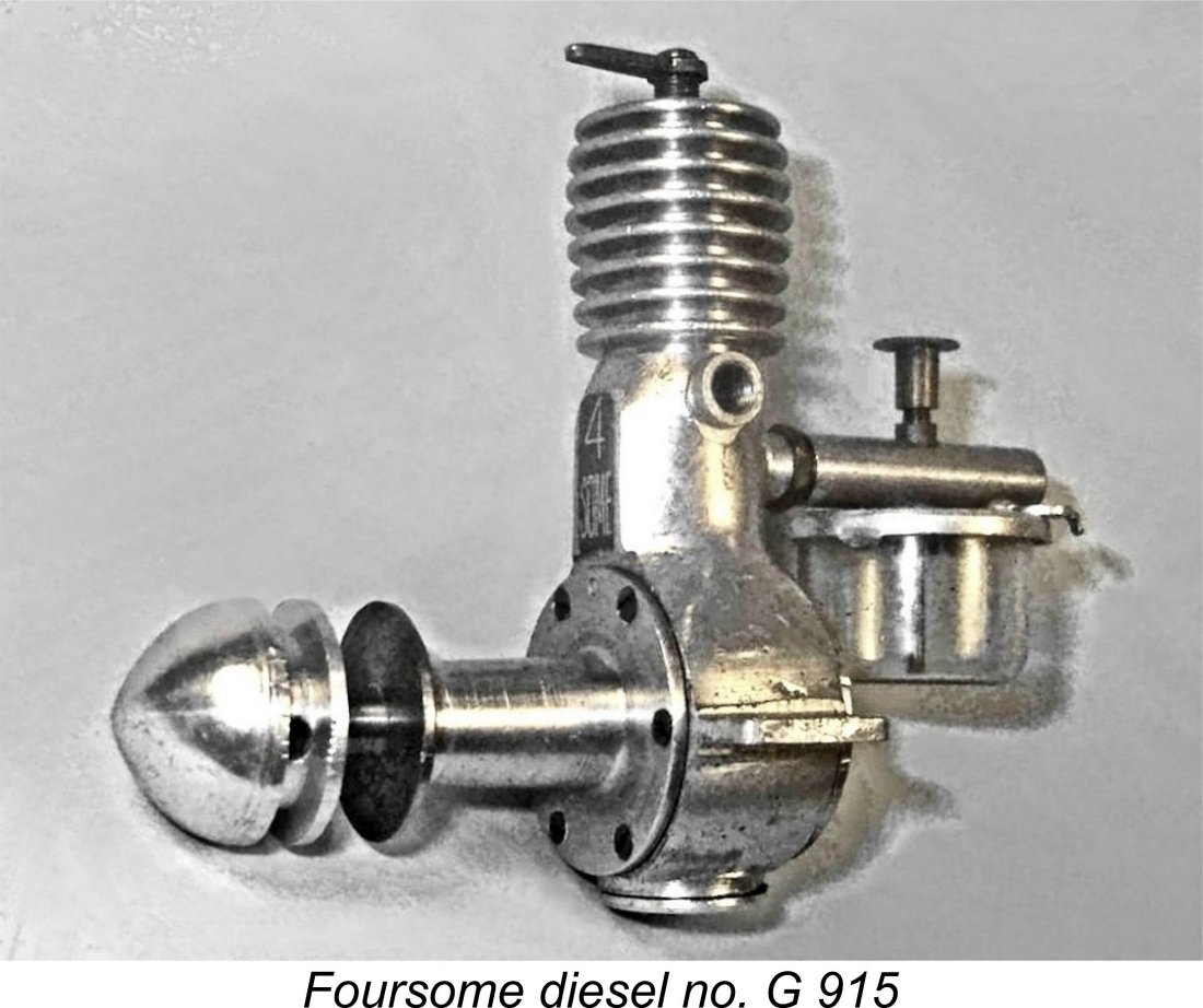
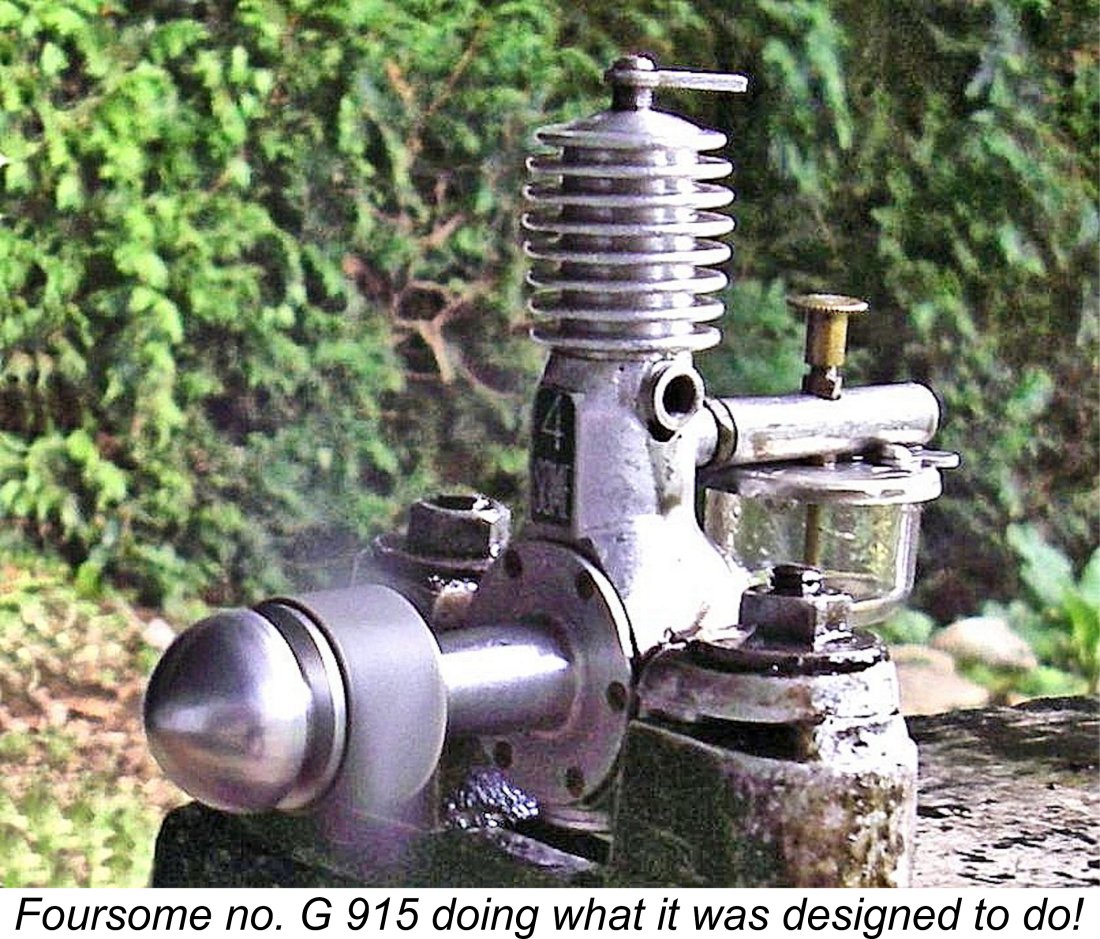
This is unfortunate, because a close examination of my example of the Foursome immediately presents us with a seemingly significant anomaly centred upon the engine’s displacement. It was always advertised as a 1.2 cc engine, a designation which it has carried down through the years. However, I’ve measured and re-measured my example many times over and keep coming up with the same figures. My engine has a bore of a nominal 13/32 in. (0.4062 in./10.318 mm) and a nominal stroke of 23/32 in. (0.7187 in./18.256 mm). This works out to a nominal displacement of 1.526 cc (0.0931 cuin.) as opposed to the 1.2 cc applied to the engine in the advertisements. The somewhat alarming stroke/bore ratio of 1.77 to 1 is the highest that I’ve ever encountered in a model I/C engine by some margin. It’s an open question whether most of the engines were in fact 1.2 cc units as advertised, with some later examples being increased to 1.53 cc in a market-driven search for more power. The extremely high stroke/bore ratio of my engine suggests that the extra displacement may have been realized through a stroke increase - the 1.77 to 1 ratio does appear rather excessive. A stroke reduction of only 1/8 in. to 19/32 in. (0.5937 in./15.081 mm) would yield a displacement of 1.26 cc with a somewhat less radical but still unusually high stroke/bore ratio of 1.46 to 1. Only the collection of bore and stroke data from a far wider sample could resolve this matter. If any reader is able to assist in this manner, please get in touch! As mentioned earlier, my illustrated 1.53 cc example of the Foursome, no. G 915, was purchased from Arthur Mullett by Laurie Ellis in 1949. Laurie had bought it new over the counter, making it appear highly unlikely that this is some kind of one-off “factory special” intended to test the effect of increasing the displacement. It weighs in at 125 gm (4.41 ounces) complete with tank - a not unreasonable figure. Laurie recalled using this example for a while, finding that it started easily and ran well enough but vibrated excessively and couldn’t compete in performance terms with the Mills 1.3. I’ll be testing these impressions in a subsequent section of this article. For whatever reason(s), the Foursome was evidently produced in relatively small numbers, hence being a very rare engine today.
The Foursome sports what must be the most unusual cylinder retention method of all time! The cylinder liner is inserted upwards through a large threaded hole in the base of the crankcase which is sealed with a screw-in plug after assembly. The main casting terminates just above the exhaust ducts, allowing the externally threaded top section of the liner to protrude above the top of the main casting. A screw-on cooling jacket is installed on the finely-threaded section of the upper liner. This acts as a nut, drawing the liner up into the case until a flange at the bottom of the liner makes contact with a seat turned around the bottom of the vertical cylinder installation bore. Eric Offen's attached image should make this arrangement clear. The lower front of the liner has a flat milled onto it which serves as part of the bypass passage. It was also likely used to retain the cylinder in the correct radial orientation while the head was being tightened. Some kind of interaction with the front housing is indicated here, because that housing is clearly stamped externally with a number 0 at the top, evidently implying that it had to be fitted in this orientation for the assembly to work. I've never removed the front housing in order to check, since this would invlove disturbing the very fine brass assembly screws.
The similarities are far too great to be coincidental, thus providing strong circumstantial evidence that the two engines were indeed products of the same designer/manufacturer. The proportions of the piston, placement of the gudgeon (wrist) pin, style of the bypass passage, very fine cylinder threads and use of the cooling fins as a "lock nut" for the cylinder liner are persuasively indicative of this, as is the general style of workmanship. The long pistons may be due to the influence of Lawrence Sparey, whose early writings advocated this as a way of maintaining the excellent compression seal required by a diesel - the benefits of a tapered bore had yet to be fully appreciated. The shared low wrist pin location is another strong family similarity, although that feature is actually dictated by geometry as placing it any higher with such long strokes would cause the rod to contact the interior piston wall at its point of maximum angular deflection (when the axis points of crankshaft, crankpin and wrist pin form a right angle triangle).
A number of the earlier examples were fitted with spring-loaded cut-outs. Engine nos. F 43 and F 90 both feature such a fitting. Thanks to Steve Hainsworth for providing the attached image of the cut-out fitted to his engine no. F 43. That on no. F 90 is identical apart from being made of brass. The cut-out appears to have been dropped on later examples. The needle valve is notable both for its very fine instrument maker’s thread and for its rather unusual construction. The component featured on my example actually consists of three components soldered together. The finely-tapered needle itself is installed in a cylindrical split thimble having a shoulder machined into the edge of its top face. A separate centrally-drilled stamped brass disc having a serrated edge locates on this shoulder and is soldered in place to serve very effectively as a finger grip. A classy touch is the inclusion of a neat little arrow stamped into the surface of the disc to indicate the needle setting. The Foursome on Test Although my ex-Laurie Ellis example no. G 915 has undoubtedly done a fair bit of running, all fits remain perfect. In particular, compression remains excellent, while there’s no detectable play in the rod bearings. Overall, the engine is extremely well made where it counts. I had run it myself many years previously following its acquisition from Laurie but had never flown it or recorded any performance data. Time to remedy the latter omission! Since the Foursome was never the subject of a published test, I was breaking new ground here!
Once running, the engine performed very steadily and was easy to adjust. The very fine thread and taper of the needle valve were much appreciated when setting the mixture. Both controls held their settings perfectly at all times. Running was very smooth, but there was a slight tendency to sag a little as the motor warmed up. Since this example is very well run in and completely free, this must be a design characteristic rather than a tightness issue. It probably relates to the engine's use of a near-parallel bore - high-temperature sag is a not-uncommon symptom with such assemblies. On the 10x4 prop, vibration levels remained within acceptable limits. However, as the speed climbed towards the mid 7,500 rpm mark, vibration became increasingly noticeable. In a test stand this was not much of an issue, but I could envision this engine being a bit of an airframe-shaker in actual service. Former user Laurie Ellis had commented on this characteristic when he passed this example on to me. The following data were obtained on test.
The above data imply a peak output of around 0.083 BHP @ 7,400 rpm for my 1.53 cc example. This essentially matched the performance recorded by Lawrence H. Sparey in his published test of the Mills 1.3 Mk. II Series I which appeared in the July 1948 issue of "Aeromodeller". Sparey reported an output for the Mills of 0.078 BHP @ 7,250 rpm. However, latter-day testing by myself and others suggests that Sparey's example may have been a somewhat sub-standard performer. Faced with a substantially cheaper and more readily available competitor delivering a directly comparable performance, the Foursome really stood no chance in the marketplace. Still, it’s a solidly-built engine having some highly unusual design characteristics as well as being extremely well made where it counts. It also starts and handles very nicely indeed. It would have been a very good “first diesel” and a perfectly satisfactory power-plant provided one was prepared to keep the revs down and accept a relatively modest level of performance. The Foursome - Advertising and Production History Thanks to the documentary research efforts of Maris Dislers, we have a pretty complete record of the advertising history of the Foursome. The engine was first advertised in the December 1947 issue of "Aeromodeller", just in time for the Christmas rush of that year. The advertisement was placed by Arthur Mullett using the Foursome Products identity mentioned earlier. The listed price was a fairly healthy £5 5s 0d (£5.25), which almost exactly matched the prevailing price of the competing Mk. I Series 2 Mills 1.3. Allowing for editorial lead time, the implication is that the Foursome must have first appeared in October 1947 or thereabouts.
However, the mid 1947 appearance of the FROG 100 at only £3 even had already triggered a steady downward trend in model engine prices in Britain. By early 1948 E.D. was selling both the 2 cc E.D. Mk. II and E.D. Comp Special diesels at £4 4s 0d (£4.20) and £4 17s 6d (£4.87) respectively. Only a considerable advantage in quality and performance terms could have justified the price of the Foursome under these market conditions. Unfortunately, while its quality was undoubtedly very high where it counted, the Foursome was undeniably lacking in the performance department. It could give an E.D. Mk. II a good run for its money but was left for dead both by the Comp Special and the Mk. II Mills 1.3. The arrival of the FROG 180 in June 1948, closely followed by the Elfin 1.8 in July 1948, underscored the Foursome’s performance and price disadvantages. By June 1948 Arthur Mullett was advertising the engine at a slightly reduced price of £5 exactly. Even this was clearly not enough - some examples obviously remained unsold for many months thereafter. Although the advertising ceased, it seems that the odd engine continued to be sold over the counter at Arthur Mullett’s shop - Laurie Ellis bought the example which I now own from Mullett in early 1949. After disappearing from the advertising for over a year, the Foursome unexpectedly made a brief out-of-the-blue re-appearance in Mullett’s advertisements for August and September 1949 at a price of £4 12s 6d (£4.63). However, these were clearly New Old Stock examples which Mullett was then trying to liquidate. This was probably the price at which Laurie Ellis bought the example which I now own. Reviewing the above chronology, it’s apparent that production of the Foursome must have commenced in around October 1947. The engine was launched with some advertising fanfare in December of that year, but sales appear to have faltered quite quickly thereafter. It’s quite likely that production only continued until mid 1948, after which further offerings represented attempts to sell off stocks already in existence. The majority of the engines appear to have borne serial numbers. Engine number F 43 has been reported by Steve Hainsworth, while the late Kjell Lindqvist reported engine number F 90. Miles Patience reports the confirmed existence of examples bearing the numbers F 118 and F 136. These numbers seem to imply that this particular sequence started at F 1 and that at least 136 examples bearing F prefixed serial numbers were constructed. There was also a serial number sequence having a G letter prefix. My own illustrated example carries the number G 915. Just to further complicate things, at least one example has also turned up bearing no serial number at all! It’s really hard to discern any logical pattern in these numbers. I can only say that it seems highly unlikely that 915 examples of the engine were made - they would surely be far more common today if that had been the case. The significance of the F and G prefixes is presently unclear. My own best guess is that the F-prefixed examples were actually 1.2 cc units as advertised, while the G series designated a batch of 1.53 cc examples. Only the receipt of further information on bore and stroke dimensions could resolve this possibility. By mid 1948, the attention of both Arthur Mullett and George Seymour had been diverted away from the Foursome towards the development of an entirely new product - the Kalper .32 cc diesel. We’ll now turn our own attention to that model, which was aimed at a totally different market niche. The Kalper .32 cc Diesel
By mid 1948 engines in the 0.75 cc and larger displacements were becoming quite commonly available, leading to the development of considerable competition among manufacturers. This as much as anything else is probably what forced the Foursome off the market. By contrast, there was very little competition in what we might term the “micro-diesel” category of engines under 0.35 cc. Noting this, George Seymour turned his attention away from the faltering Foursome towards the development of a little 0.32 cc sideport diesel which was destined to become famous as the Kalper .32. The design goal appears to have been to create a sideport diesel engine of more or less the same physical size as the Kemp Hawk with which it would be competing, but developing considerably more power. As we shall see, Seymour succeeded completely in meeting this goal. The initial rendition of his fine little engine seems to have appeared in July 1948 or thereabouts. It might be supposed that the intent behind the introduction of such small engines was to open up a new field in aeromodelling, but the underlying concept actually seems to have been the simple replacement of rubber motors and their progressively-declining outputs during flight with a small I/C engine with its steady and controllable output during the easily-timed run. Such engines were initially seen primarily as replacements for rubber power in the same types of model.
The first model of the Kalper .32 was basically very similar to the earlier Foursome model. Like its Foursome predecessor, it was a very long-stroke engine, having nominal bore and stroke dimensions of 0.250 in. (6.35 mm) and 0.406 in. (10.31 mm) for a design displacement of 0.327 cc (0.0199 cuin.) and a stroke/bore ratio of a massive 1.62:1. This is among the highest stroke/bore ratios of my personal experience, being exceeded only by the larger Foursome model from the same source. Seymour evidently liked long strokes!
The original Kalper variant (which I will refer to henceforth as the Mk. I) featured a conventional rear-mounted intake venturi, exactly like the Foursome. Its construction was somewhat simplified, with a screw-in front housing being employed in place of the Foursome’s multiple-screw attachment. An interesting feature of this front housing was the fact that it used a left-hand thread, presumably to discourage unwanted unscrewing during operation in the normal direction. The crankcase was bored and threaded clean through, forcing the use of a left-hand thread for the backplate as well. However, in most respects the Kalper .32 Mk. I was simply a scaled-down Foursome. Its manufacturers were identified from the outset as Seymour, Hylda & Co. of Southwick, Sussex. A rather classy feature of the Kalper was the plastic disc which was affixed to the front of the crankcase and displayed the maker’s name and location - very much an "instrument maker's " touch. One key departure from the design of the Foursome was the cylinder installation. The bypass was augmented as before by the inclusion of a flat on the outer front cylinder wall, but the base flange which had located the Foursome cylinder vertically was absent in the Kalper. Instead, the cylinder liner screwed into the internally-threaded crankcase installation bore from the top on very fine 60 tpi threads cut externally onto the lower cylinder wall. This was continued until the ports were at the correct height and radial orientation, after which the head was screwed down onto the protruding externally-threaded top of the liner, thus acting as a "lock nut" to keep the liner in position. The liner would have to be held in place during this operation to keep the ports correctly aligned - maybe by poking a toothpick or similar non-marring rod through the exhaust. On the plus side, the port timing could be varied to a degree depending on how far one screwed the cylinder in before locking. Unusual to say the least!
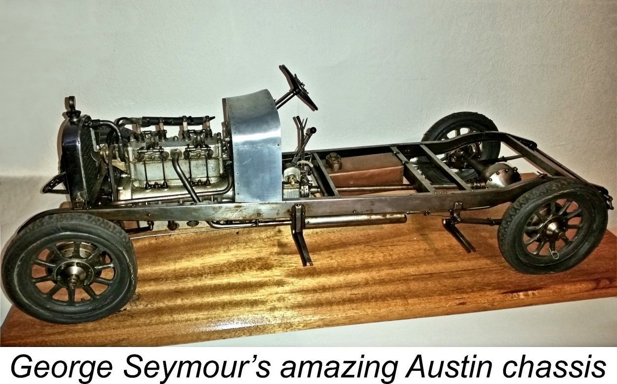
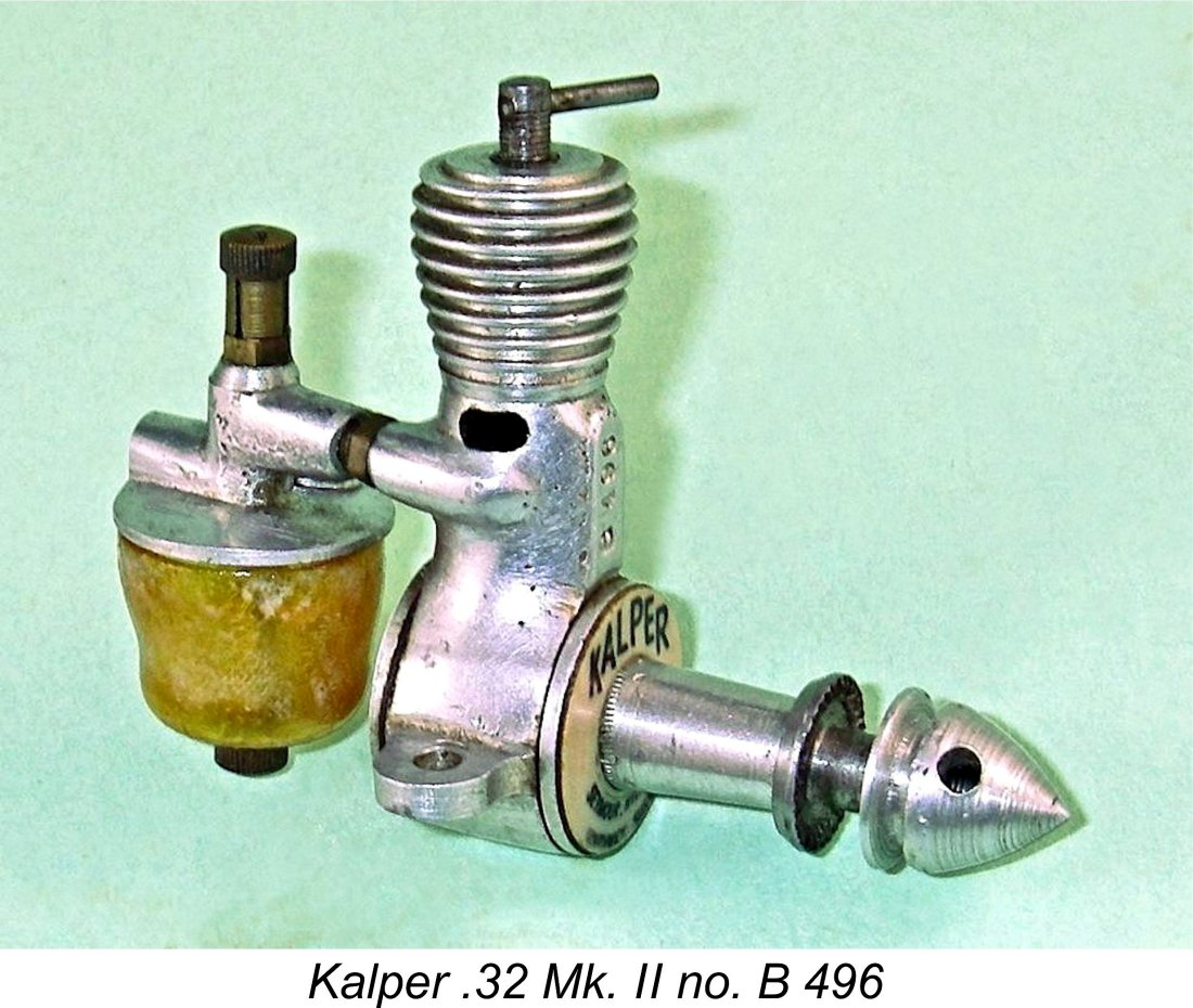
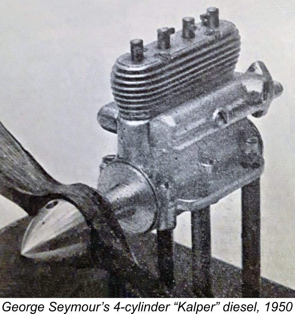
Like the Foursome, the Kalper .32 was initially distributed solely by Arthur Mullett. The engine appears to have become quite popular in fairly short order, since Mullett did not feel it to be necessary to advertise the engine during its first six months or so on the market - evidently over-the-counter sales by word of mouth absorbed the full production. This marketplace acceptance encouraged George Seymour to develop a revised version of the engine which I will refer to as the Mk. II variant. The advertising record (see below) indicates that this revised version appeared in June or July 1949. Interestingly enough, it appears to The second variant differed from the original version in having the induction port relocated from the rear of the cylinder to the side, thus avoiding any fouling problems with the gudgeon pin while also potentially allowing an increase in the size of the port. The design also featured a most unusual “dog-leg” intake tract which allowed the fuel jet to be aligned concentrically with the upward portion of the intake rather than being oriented transversely in the usual way - the accompanying sectioned view from the "Model Aircraft" test report (see below) should make this clear. However, the design was otherwise little changed apart from a slight alteration to the script style on the plastic name-disc. The purpose of the “dog leg” is open to debate, although Maris Dislers has come up with what appears to me to be a completely logical explanation. His idea is based upon the fact that very small engines are notoriously easy to flood by finger-choking. The vertical dog-leg All examples of this second variant which have come to my attention have borne serial numbers. Jan Huning’s example bore the number B 177. I own engine nos. B 496 and B 547, while Steve Hainsworth reports owning engine number B 559. Reader Peter Wallis reported owning engine no. B 592. The example tested by Peter Chinn (see below) bore the number B 538. The implication here is that the B series started at B 1 and that at least 592 examples were produced. Given the engine’s approximately 20 month production life, this is entirely possible, even for a small artisan workshop. It would be tempting to conclude that the Mk. I engines carried A-prefix numbers while the Mk. II examples It's worth mentioning at this point that during the production life of the Kalper .32, George Seymour flexed his model engineering muscles and produced a single example of a remarkable 1.3 cc in-line four-cylinder derivative of the Kalper. This amazing little unit was featured in the pages of "Model Engineer" magazine in September 1950 together with the attached photograph. It had been entered in the 1950 "Model Engineer" exhibition, at which Seymour won a Bronze medal for his scale-model bicycle complete with scale chain, of which he made every individual link himself! Seymour's little four-cylinder masterpiece was stated to have been the smallest multi-cylinder I/C engine featured at the 1950 exhibition. Although it was clearly rather impractical as a model powerplant, it serves as a glowing testament to Seymour's amazing model engineering capabilities. Why on earth didn't it win a medal ....?!? Regardless, it must have sounded pretty impressive when running! Wonder where it is today ............. The Kalper .32 on Test The original Mk. I version of the Kalper was the subject of a test by Lawrence H. Sparey which appeared in the November 1948 issue of “Aeromodeller” magazine. It is the publication date of this test report which pretty much confims the July 1948 introductory date of the engine. Any later date would not have afforded Sparey sufficient time to obtain the engine, complete the test and submit his report in compliance with the late September editorial deadline for the November issue (which actually hit the news-stands in mid October). Sparey characterised the engine as displaying what he described as “a marked absence of “fussiness” in the controls”, evidently finding its starting and running qualities to be very good. He measured a peak output of 0.0099 BHP @ 10,250 rpm, which he considered to be “about what might be expected from an engine of this tiny size”.
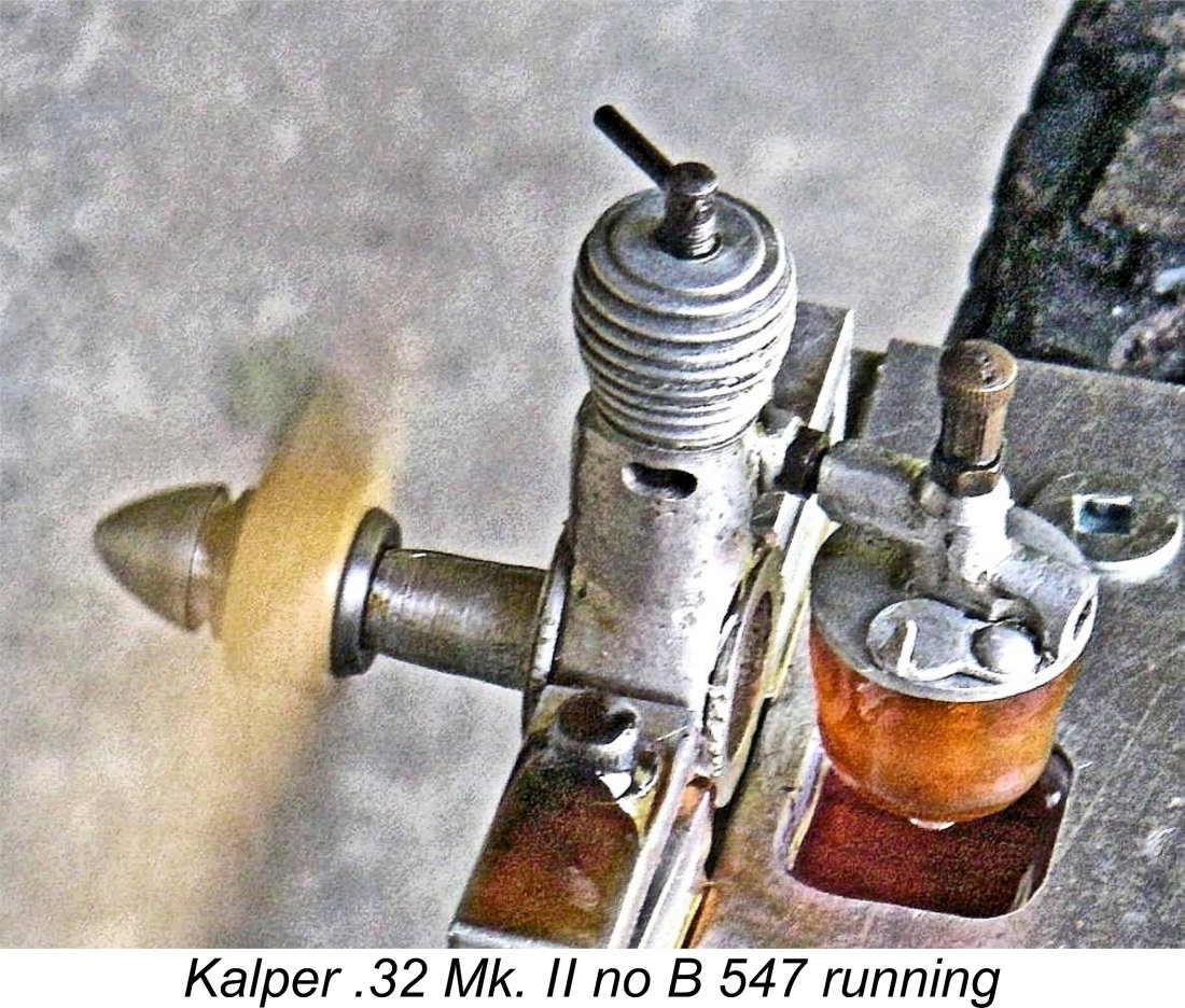
I've run tests on several examples of the Kalper .32 Mk. II in my own possession, finding the little beauty to be a pure delight to run. It starts very easily using standard methods - you forget just how small an engine it really is. Control response is outstanding - in particular, the very fine thread and shallow taper on the needle valve render the engine completely free from the typical "micro-diesel" sensitivity to the needle setting. The slightly better of the two examples of the Kalper .32 Mk. II in my possession yielded the following data on test.
The above data suggest a peak output for this example of around 0.0171 BHP @ 9,200 rpm. These figures are completely consistent with Chinn's findings, particularly bearing in mind that differences in performance between different examples of the same production engine tend to become more exaggerated with decreasing displacements. My tested ex-Laurie Ellis example has been well used, hence probably being better run-in than Chinn's test unit. An informative video showing one of these little gems running may be found here. The Kalper .32 - Production and Marketing History
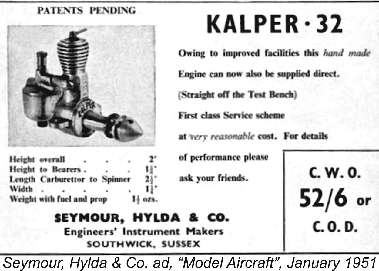
The initial advertisement used the Mk. I drawing which had been featured in the “Aeromodeller” test report, presumably with the permission of the magazine. The Mullett advertisement for June 1949 used the same drawing. The advertised price from the outset was a remarkably low £2 12s 6d (£2.63). Dream on ............ a matching 6x5 airscrew was also offered at a price of 3 shillings (£0.15). Given the intricate nature of the design and the fine workmanship required, it’s very difficult to see how the engine could be offered at this price with a reasonable financial return to the manufacturer. A very low manufacturer's overhead is implied. Such a price could only make economic sense to a manufacturer working at home in rent-free premises and using fully paid-for equipment. Mullett’s advertisement for July 1949 omitted the drawing, confining itself to the inclusion of the Kalper in the list of engines available through the shop. This may From this point onwards, the distribution of the Kalper clearly became more widespread. The engine began to appear in the advertisements of model dealers other than either Arthur Mullett or South Coast Models. Perhaps this was the reason for the apparent split - Mullett may have wished to retain exclusive marketing rights, while Seymour may have wanted to broaden his geographic sales outreach. Perhaps he had his eye upon the possibility of increased production but needed an expanded marketing base to justify this. The most historically significant advertisement was that placed by the wholesale distributor Cartwright’s Model Supplies Ltd. of Elystan Street, London in the September 1949 issue of “Aeromodeller”. This was the first advertisement to feature the Mk. II version of the engine with the ”dog-leg” intake and side location of the induction port. Once again allowing for editorial lead time, this appears to date the appearance of that version of the Kalper to around June or July of 1949. Interestingly enough, Cartwright’s were referred to in the The engine also appeared in advertisements placed by the retail outlets Bud Morgan, Gregory’s, John Lester and Roland Scott, indicating quite widespread geographic distribution. In addition, Seymour, Hylda & Co. began to place advertisements in their own right. As of September 1950 they were stating that the engine could be purchased directly from them at the Southwick address.
The final advertisement that Maris Dislers was able to find was a half-page placement by Seymour, Hylda & Co. in the March 1951 issue of “Model Aircraft”. It was at about this time that George Seymour contracted an illness of some kind which led very quickly to his untimely demise at age 67. This unhappy event seems to have put an immediate end to production of the Kalper. There’s little doubt in my mind that the Kalper was missed by at least some members of the modelling fraternity. It seems to have been quite highly regarded among those British sport and scale free flight enthusiasts who favoured small models - deservedly so in my opinion. In the absence of any clear understanding of the serial numbering system, it’s impossible to develop a credible estimate of the number of engines produced. Al that can be said is that the Mk. I version is far less commonly encountered today than the Mk. II model, and even the latter variant is quite rare. The engines appear to have been individually hand-crafted to a large extent, just as claimed in the advertising. This being the case, it’s unlikely that production figures were particularly high. Unfortunately, we’ll have to leave it there for now pending the uncovering of more information. The Kalper .32 Replicas
The late Arne Hende arranged for the production of a series of replicas of the Mk. I version of the engine. If Arne ran true to form, it’s likely that a batch of 100 examples was made to Arne’s usual high standard. I don't have one of these replicas myself, but my friend and colleague Chris Murphy of New Zealand has engine number 030 of this series, upon which he posted some comments on a widely-read forum. Chris commented that the Hende replica was a good runner, as well as being very well made in keeping with Arne Hende's usual standards. He found that it would turn a Cox 6x3 black nylon prop at around 7,000 rpm (roughly 0.0096 BHP at that speed).
Chris's endorsement notwithstanding, the Mk. II Kalper replica seems to have been one of VA’s less successful efforts if Maris Dislers’ experience is anything to go by. Inspired by our exchanges during the preparation of this article, Maris dug out his own VA replica to give it a go. His litany of problems would drive many of us to drink! First, he found that the piston/liner fit was too loose. Fortuitously enough, he just happened to have a spare set handy - lucky! This cured that problem, but then he found that the engine was a bit of a challenge to start and wouldn’t needle consistently. He took some measurements and made some calculations, finding that the vertical section of the intake surrounding the fuel jet was sized so that the theoretical minimum operating speed for effective suction was all of 13,000 rpm! No chance ………. Maris made a rough ‘n ready restrictor from a folded piece of aluminium alloy sheet and inserted this into the vertical section of the “dog-leg” intake. The engine now started easily with just two finger chokes and ran “sort of OK” but with relatively little power and an ongoing inconsistency, with the fuel mixture hunting from rich to lean. A switch to a different fuel produced very rich running, during which the cylinder blew out of the case! AAAARRRGGGHHH!?#! Inspection showed that the very fine case thread did not appear to be stripped, but was evidently too sloppy a fit. With a very fine thread (7.8 x 0.4 mm according to Maris) almost no “slop” can be tolerated due to the minimal thread depth. Evidently VA got this wrong. Maris found that the head installation thread was also on the sloppy side. The only possible fix appears to be an electroless nickel plating treatment of the cylinder thread to take up some of the slop. Having found some of VA’s other work to be of quite acceptable quality, and noting Chris Murphy's apparent success, I reckon that it’s possible that Maris got a bad one. Even so, I’m glad to have my two originals! Dismantling
Of course, circumstances can arise which make it imperative to dismantle the engine - a broken wrist pin or some similar catastrophe, or just a need for a rebore. If you really do have to take this drastic step, remember those ultra-fine instrument maker’s threads and treat them with great respect. When reassembling, do not overtighten the cooling jacket - finger-tight when warm is quite sufficient. Also be mindful of the fact that the crankcase is threaded clean through with a left-hand thread, so both the front main bearing housing and backplate unscrew in the left-hand direction - opposite to normal. Thankfully, MEN reader Jan Huning was kind enough to provide a detailed description of the Kalper’s construction. If dismantling is contemplated, prior reference should be made to this invaluable document, which remains available on MEN. An Interesting Factory Replacement
Peter wrote to the manufacturers (who were still in business) to request a replacement. As the attached image shows, what he received was nothing like the original assembly based on a casting. Instead, the replacement intake was a straight component machined from brass barstock with no Z-bend. The tank was completely different, while the needle valve was a far more substantial component than the original. The replacement intake certainly looks considerably more sturdy than the original. However, it would be a little unusual for a manufacturer to supply a non-standard replacement without some very persuasive reason. I suspect that Peter's experience was not an isolated incident - it seems likely that experience had shown that the design was prone to such fractures. Either the supply of spare castings had dried up, or the manufacturers had decided to supply stronger replcements for those that did fail. Regardless of the reason, it's possible that other examples featuring similar intakes may show up. At least we now have an explanation for the existence of any such engines! My thanks to Peter Wallis for making me aware of this interesting modification. Summary and Conclusion It should surely be obvious from what has been presented above that the Foursome and Kalper engines share a common design heritage - the structural similarities are far too striking to be coincidental. If we believe the attribution in the “Model Engineer” obituary (and we have no evidentiary reason not to do so), the two engines were both designed by George Seymour.
The 1.2 cc designation which has always been applied to the Foursome remains a matter for debate. There’s no question at all that my example of the engine is a 1.53 cc unit - I’ve checked and re-checked my measurements too many times and on separate occasions for this to be in doubt. Whether they were all like this or whether my engine was one of a modified series having a larger displacement and a different serial numbering sequence, presumably in a market-driven search for more power, remains open to discussion. The Foursome seems to have had a short production life of only some 8 months or so. The Kalper did somewhat better than this - the first model seems to have been in limited production for some 10 months, while the Mk. II version remained in production for 20 months from mid 1949 until George Seymour’s untimely death in early 1951. It was almost certainly that sad event that brought production to an end. Both engines share a number of features which are pretty much unique in British model diesel design practise. The method of installing the cylinders has no parallel of which I’m aware, while the very fine “instrument maker’s” threads used in both models are highly indicative of a background in that field. The engines are also built to very high toolroom standards, particularly where it really counts. Taken all in all, these are two of the more individualistic and hence interesting British sideport diesels of the early post-WW2 era. Both are fine-handling and smooth-running engines which were sufficiently well-built to wear extremely well. They don’t appear on the present-day market very often, and when they do they tend to command quite high prices. Still, if you ever get a chance to handle one or see it in action, don’t hesitate - you’ll enjoy the experience!! _____________________________ Article © Adrian C. Duncan, Coquitlam, British Columbia, Canada First published on MEN July 2008 Revised edition first published on this website November 2021
|
||
 If you ever succumbed to the urge to head down south of London, England to the Channel Coast at Brighton to experience the famous
 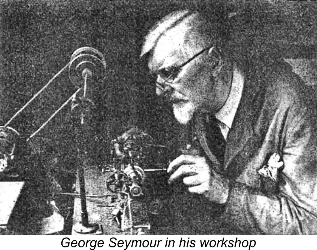 George C. Seymour was born in 1884 in Portslade, a western suburb of Brighton in Sussex. The family residence was located at 17 Carlton Terrace in Portslade. George Seymour assumed ownership of this property in the late 1920’s, presumably through inheritance. Today the location has been redeveloped for commercial purposes.
 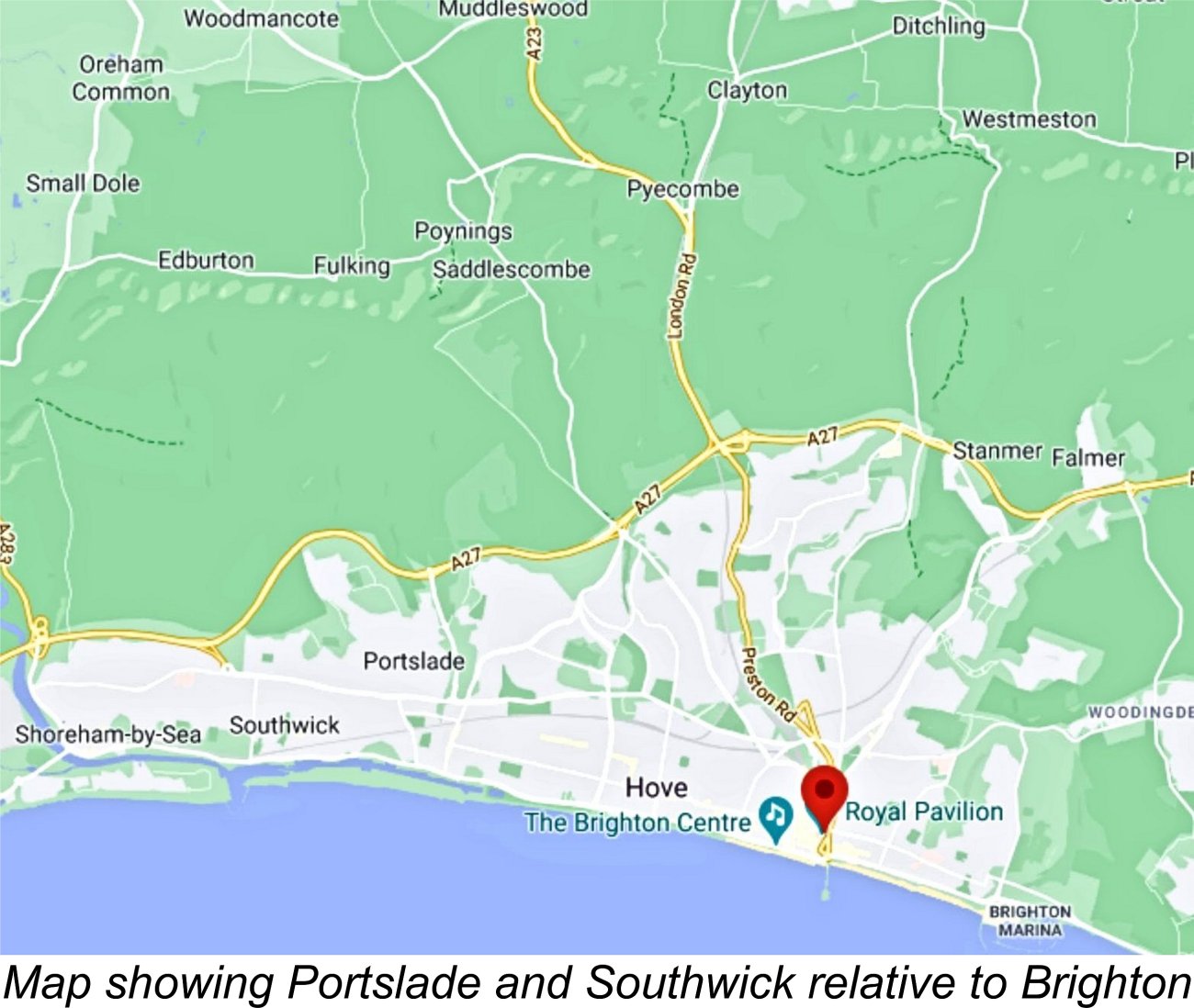 The company’s full name was Seymour, Hylda & Co., Engineers’ Instrument Makers. This company appears to have remained a one-man (or family) “cottage industry” operation throughout - both Seymour's wife and his son may have been involved. The company's pre-war premises were cited as Seymour’s residential address at 17 Carlton Terrace in Portslade. However, by 1947 Seymour had relocated to a 1920’s bungalow called “Kusaie” on Kingston Lane in nearby Southwick. As far as Miles Patience could determine, this house still existed in 2020!
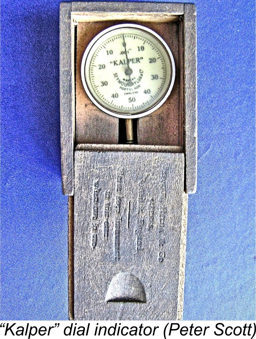
 According to his obituary which appeared in the June 7
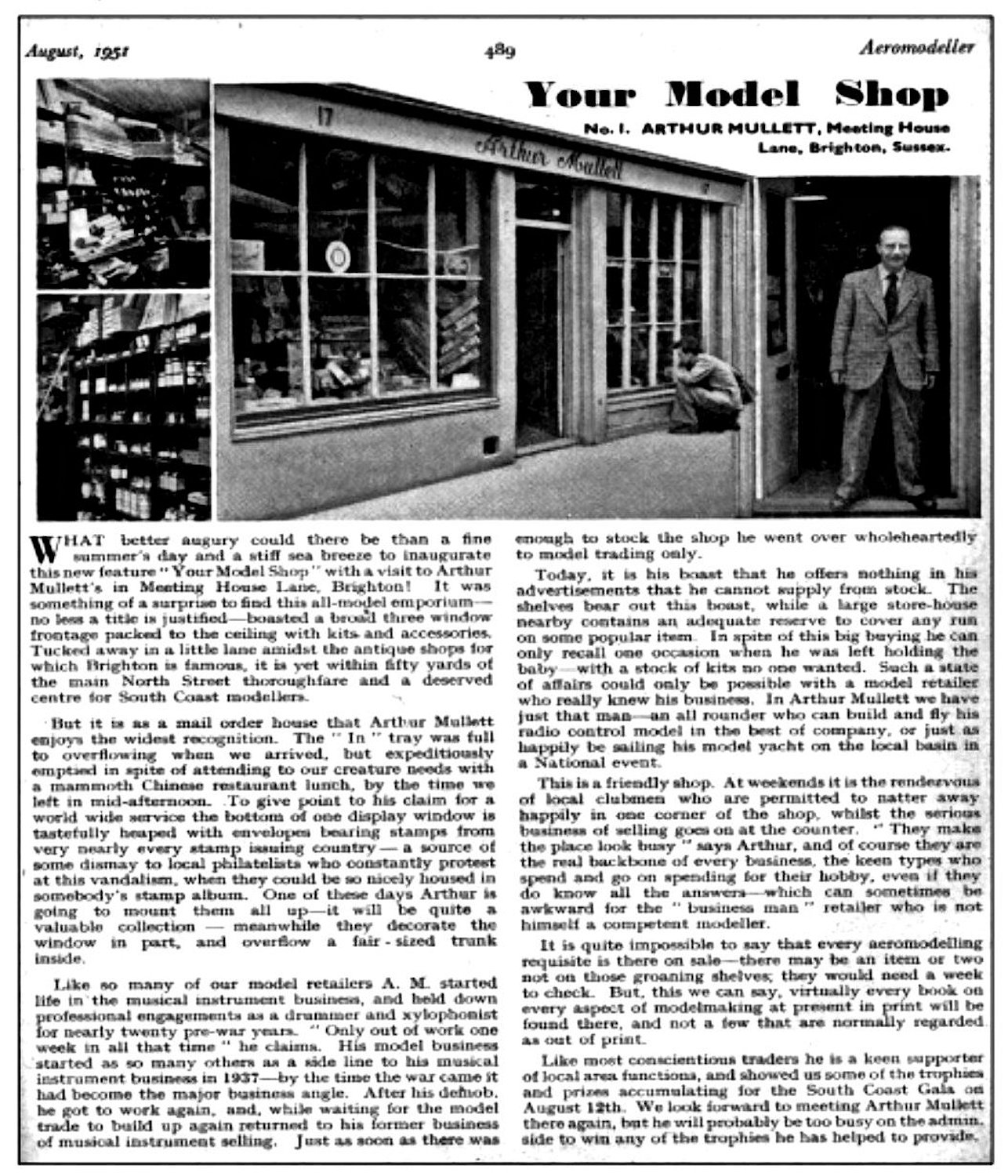
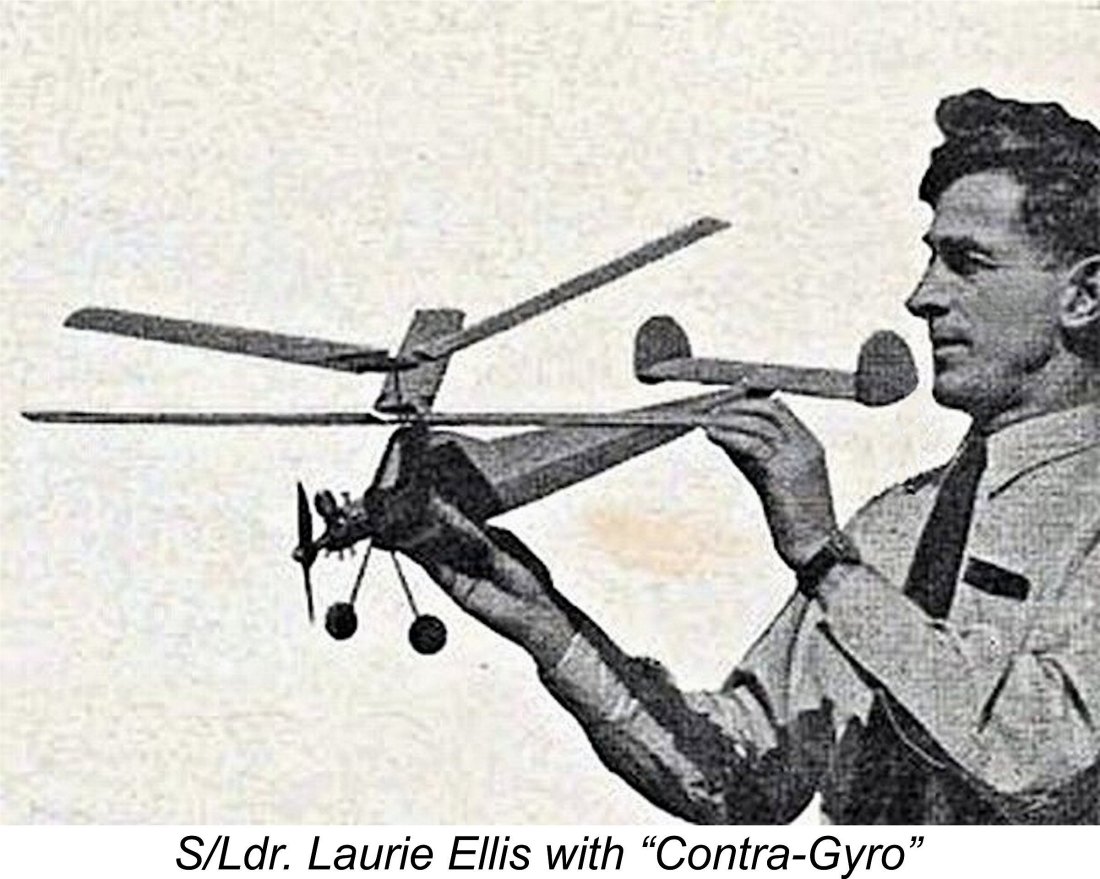 Some direct support for this view comes from the very clear and carefully recorded recollections of my late Canadian friend, Squadron Leader Laurie Ellis, RCAF, from whom I obtained both my example of the Foursome and one of my Kalper .32 Mk. II units way back in the late 1970’s. After service in Coastal Command during WW2, Laurie remained in the RCAF for some years thereafter, continuing to be stationed in England and becoming a well-known published model designer (anyone else remember the
 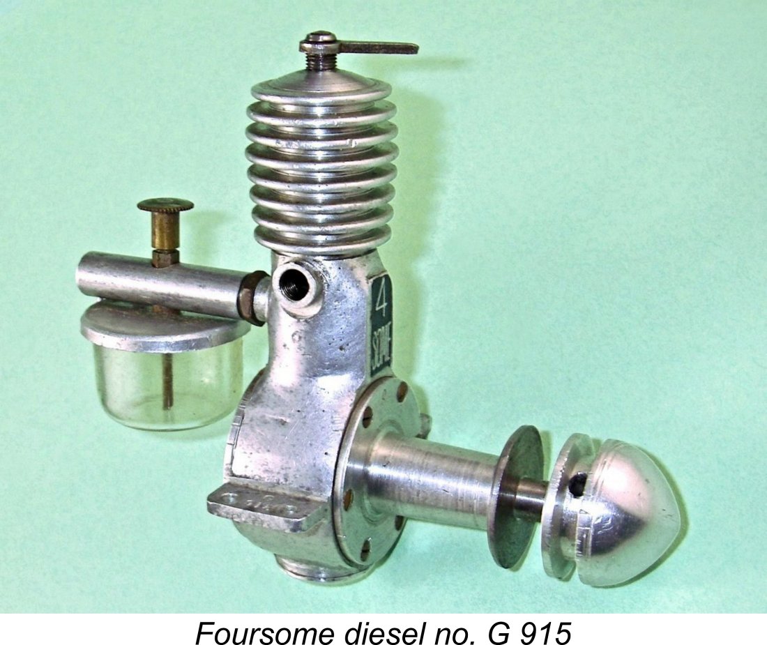 The Foursome was included in the data table which constituted Appendix II of Ron Warring's early 1949 book "
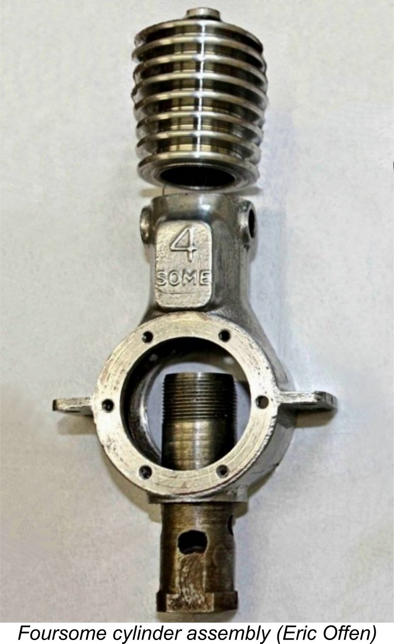 Generally speaking, the Foursome is a perfectly conventional sideport diesel engine of its era. However, its construction presents us with some highly unusual features, perhaps reflecting its designer’s instrument-making background. For one thing, the front cover is held on by 6 elegant but rather fragile-looking brass countersunk screws, very reminiscent of instrument-making practise. In addition, all threads used are unusually fine, once again reflecting an instrument-making heritage.
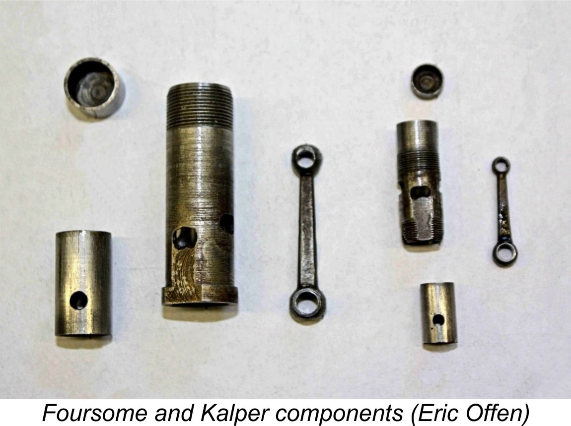 The internal structure of the Foursome was a bit of a mystery until Eric Offen provided a few photographs taken while he had one of these engines apart for restoration. I'm extremely grateful to Eric for his kindness in making these images available. Eric provided the photograph at the left which shows the Foursome and (later) Kalper cylinders, pistons and nicely machined steel rods, side by side.
 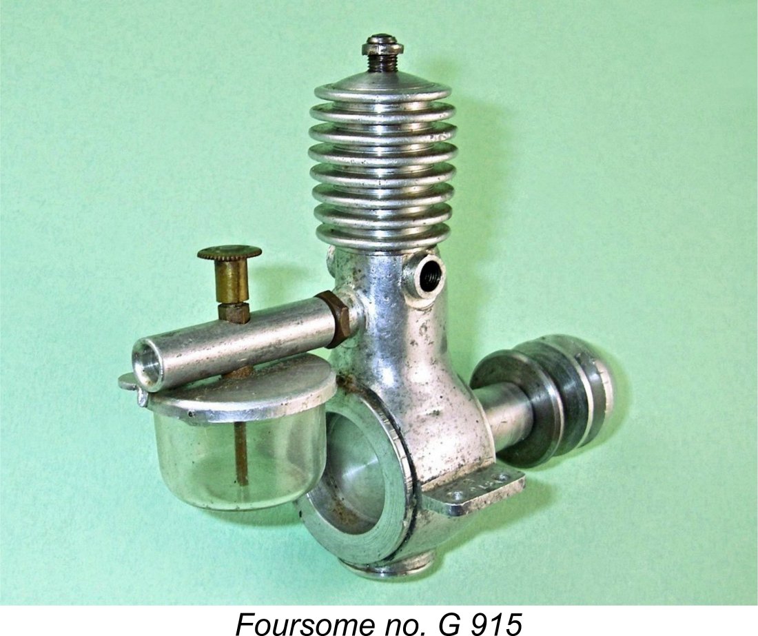 The Foursome’s twin exhaust stubs are faced and internally tapped, indicating that some kind of threaded extension stacks could be installed if desired. The "4 SOME" designation is cast in relief onto the front of the casting on the bypass "bulge" and is highlighted by the use of an area of green enamel paint surrounding the identification. Former owner Laurie Ellis assured me that the engine was supplied in that state. He also recalled that some of them were painted red, but I can't confirm that. By contrast, the incorrectly-dated example shown on page 73 of
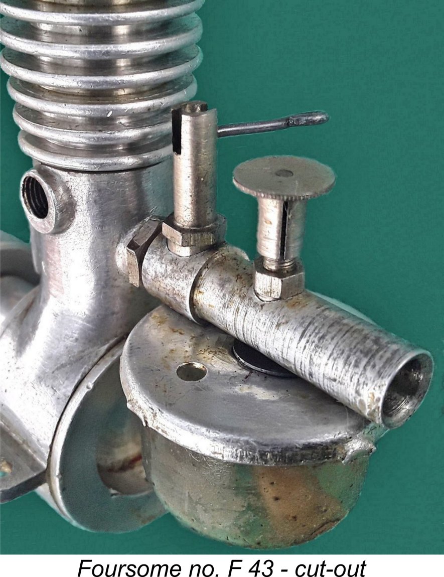
 I began with a Taipan 10x4 prop to give myself plenty of flywheel. As it turned out, I needn’t have worried! The Foursome started very easily indeed on all props tested - almost like a Mills, in fact. A couple of choked flicks were all that it required as a preliminary.
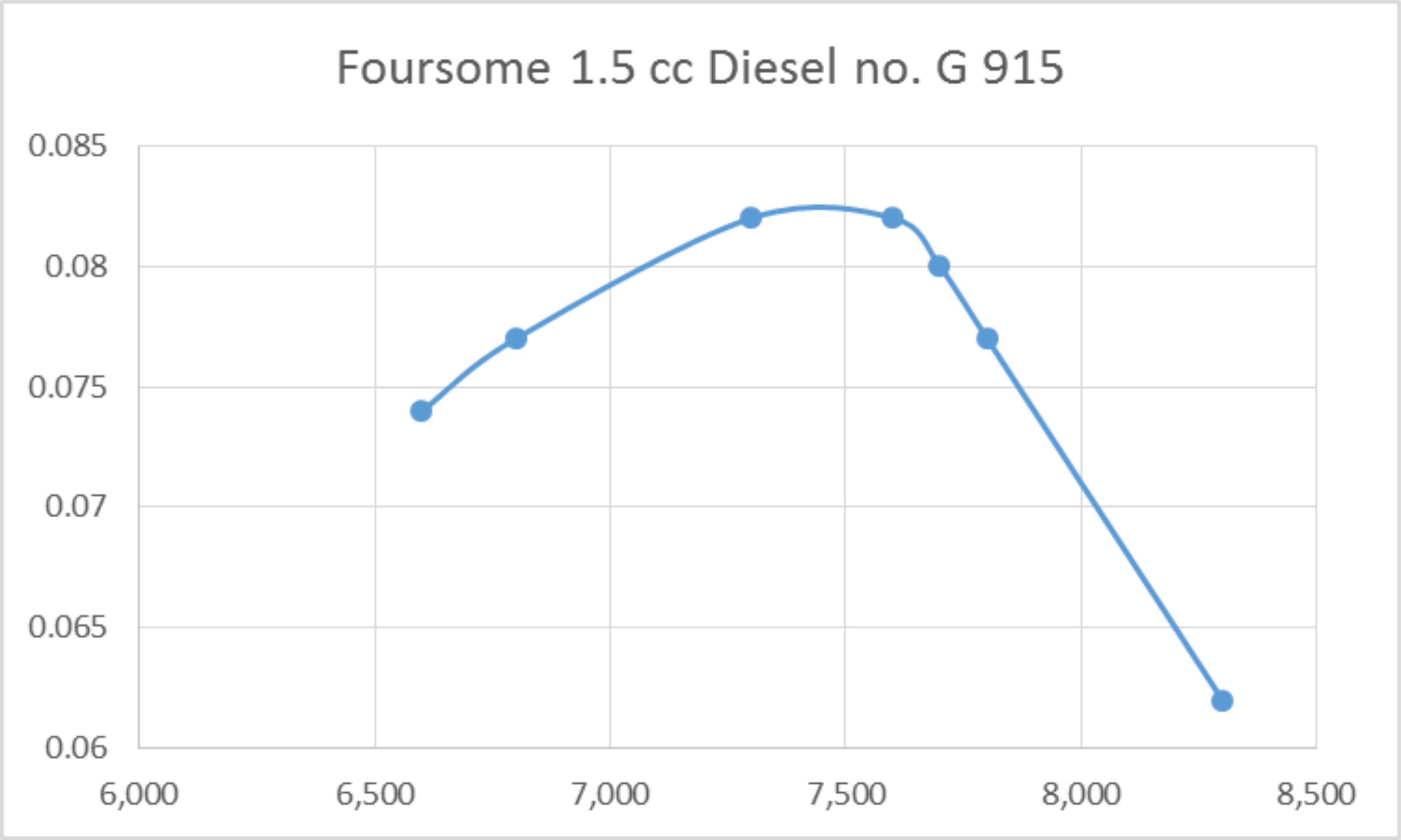
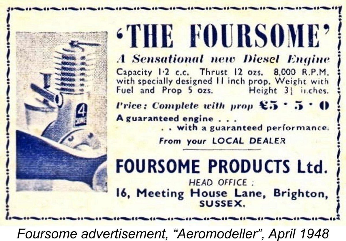 The same advertisement appeared in the January, February, April and May 1948 issues of the magazine at the same price. The engine was also featured in Henry J. Nicholl's advertisement in the February 1948 issue of "Aeromodeller". It's noteworthy that the example illustrated in these advertisements did not feature the cut-out - perhaps it was an optional accessory.
 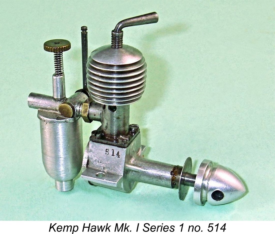 The January 1948 introduction of the
 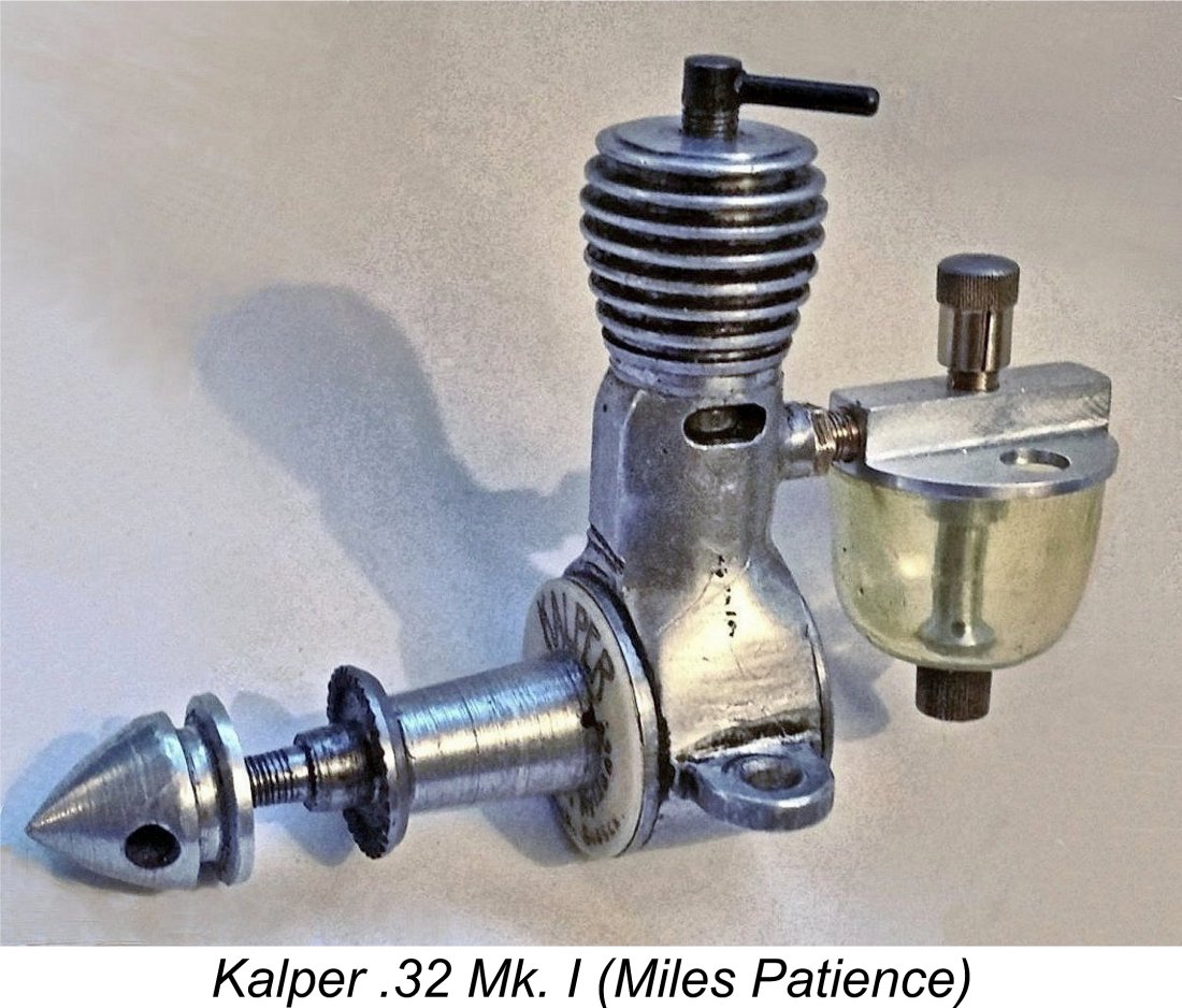 While there seems to be some residual uncertainty regarding the identity of the Foursome’s manufacturer (although I personally consider it to be far more likely than not that it was George Seymour’s company), there’s none at all with respect to the Kalper. That model was definitely stated from the outset to have been manufactured by Seymour, Hylda & Co. “Kalper” was of course Seymour's own trade name which he had used since before WW2.
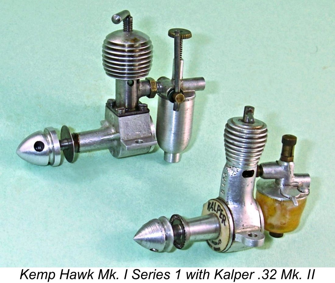
 Most of the engines seem to have borne serial numbers in keeping with George Seymour’s usual practise, but the illustrated example owned by Miles Patience is not numbered at all. The only confirmed serial numbers for the Mk. I Kalper that I have come up with so far are A 767 and A 790, the latter example being illustrated by Mike Clanford in his
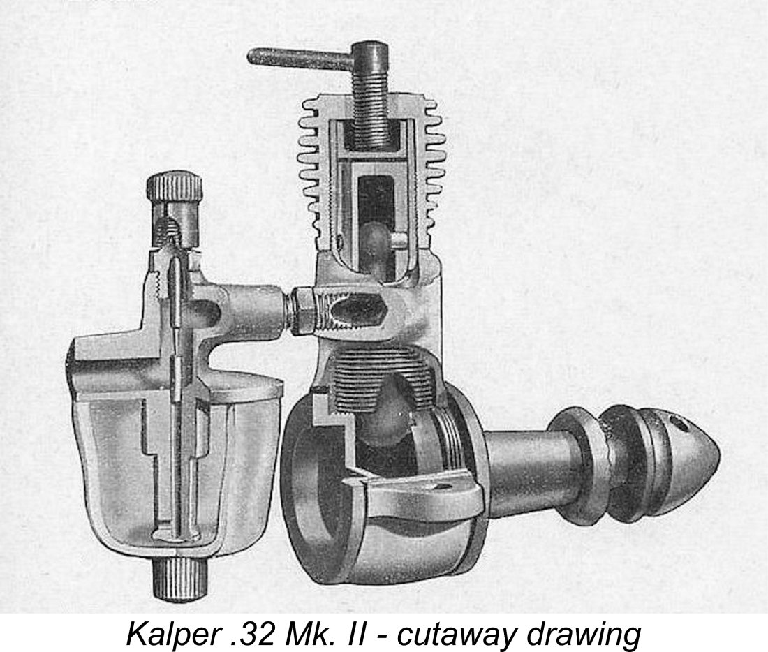
 The second Mk. II variant was also the subject of a
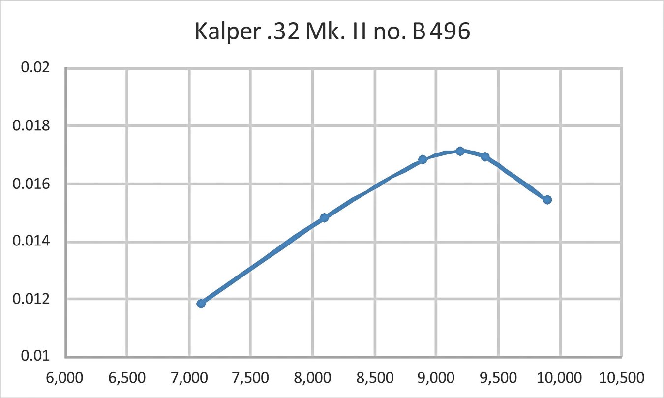
 The little Kalper was clearly in existence as of the second half of 1948 - the date of Sparey’s test confirms as much. However, the first national advertisement for the engine that Maris Dislers could find was a placement by Arthur Mullett in the May 1949 issue of “Aeromodeller”. Presumably up to that point over-the-counter or mail-order sales through Mullett by word of mouth had absorbed the full production of the engine.
 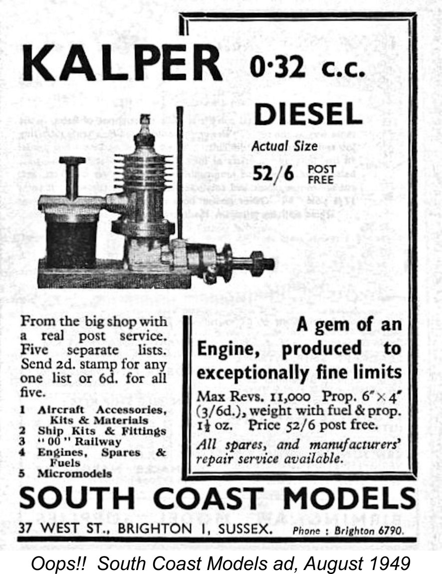 imply that there had been a cooling-off in the relationship between Mullett and Seymour, because in August 1949 we find the engine being prominently featured by a rival Brighton model shop, South Coast Models of 37 West Street. A fascinating feature of this advertisement was an evident faux pas which resulted in the captioned "actual size" image of the engine showing an
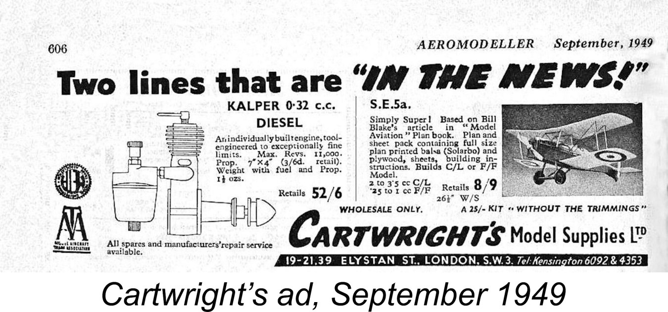
 This may imply that by that point in time demand from the dealers was declining as customer demand also dwindled. Maris Dislers has speculated that the novelty appeal of the really small diesels may by then have run its course, at least for the time being. Such a situation would also be fostered by the fact that neither the model plan publishers nor the kit manufacturers had supported the micro-diesel movement with new designs for such engines. If you bought a Kalper, you were on your own as far as coming up with a suitable model was concerned.
 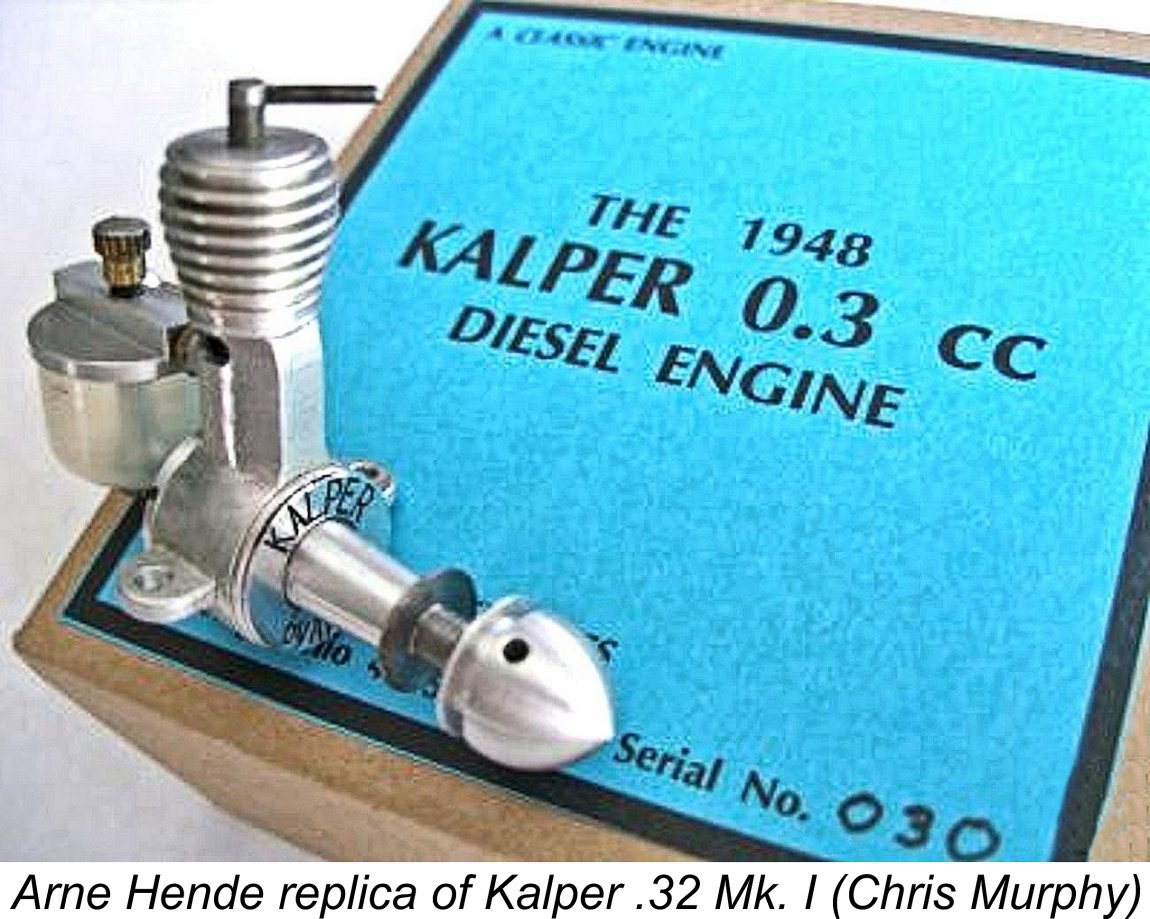 Engines of the rarity and interest of the Kalper have seldom escaped the attention of the replicator. The little Kalper was certainly no exception to this rule. Both the Mk. I and Mk. II versions of the engine have been replicated for the collector market.
 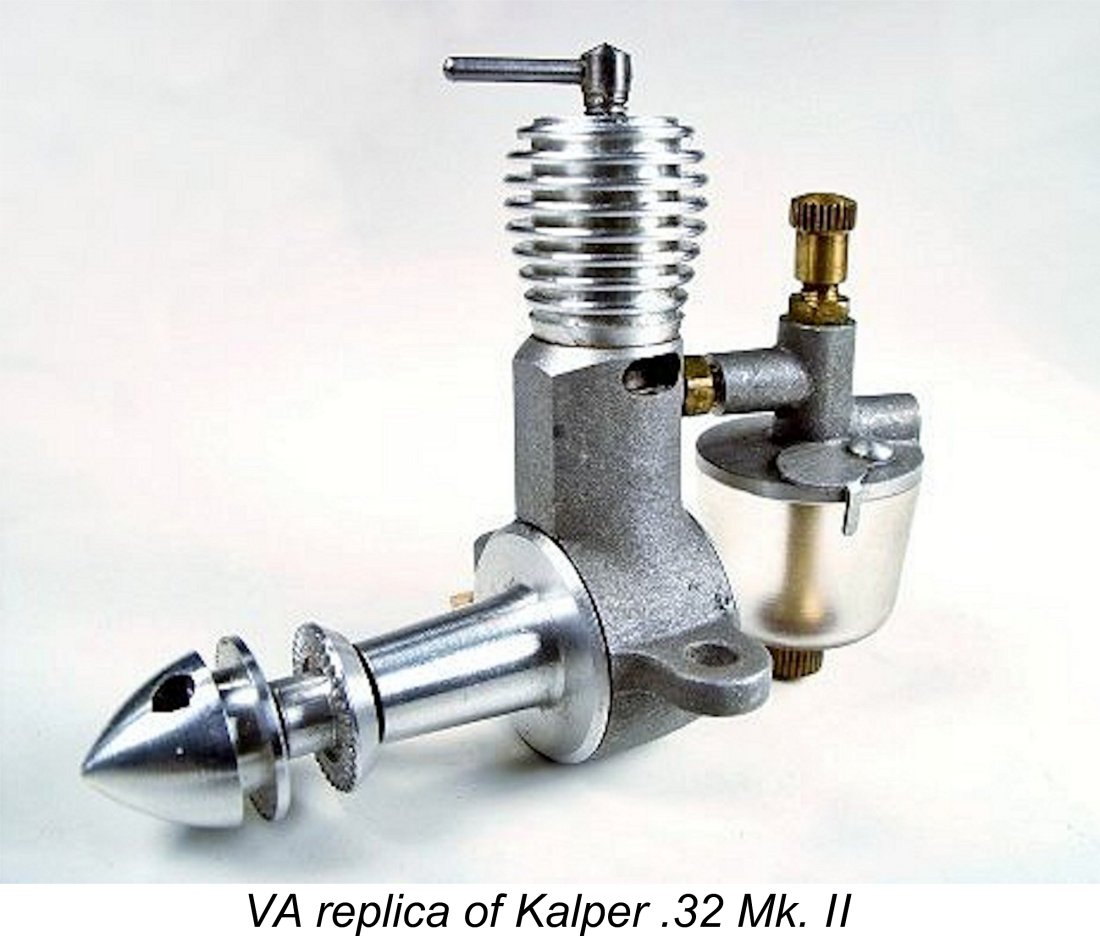 The replica of the Mk. II variant which was produced in Russia by VA seems to be somewhat better known. Chris Murphy also has one of these replicas. He commented that while it was not as nicely made as the Arne Hende replica of the Mk. I Kalper, it ran very well and was some 1000 rpm faster on the same Cox 6x3 prop - around 0.014 BHP @ 8,000 rpm, whch is very consistent with my own findings for the original. This performance differential supports the previously-cited possibility that there were some porting differences between the Mk. I and Mk. II models which led to the latter model out-performing its predecessor.
 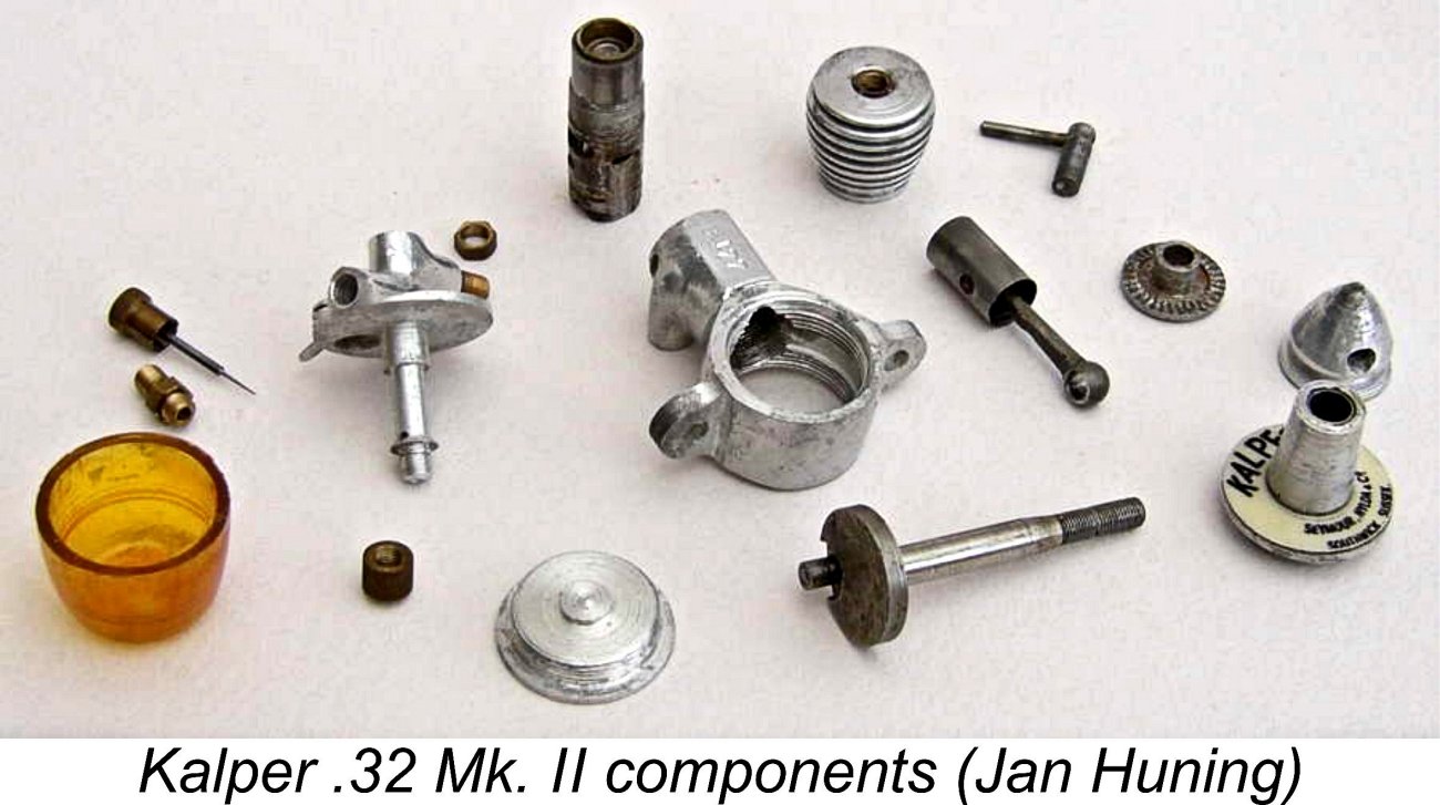 Having recounted Maris’s woes with the VA replica, I feel that I should say something here about dismantling these engines. This is pretty easy - don’t even think about it!! If you have an example that is well screwed together and runs dependably, be very thankful - leave it well alone and just enjoy running it! Those ultra-fine 60 tpi threads simply won’t take too much repeated loosening and tightening - why subject them to such stresses unnecessarily?!?
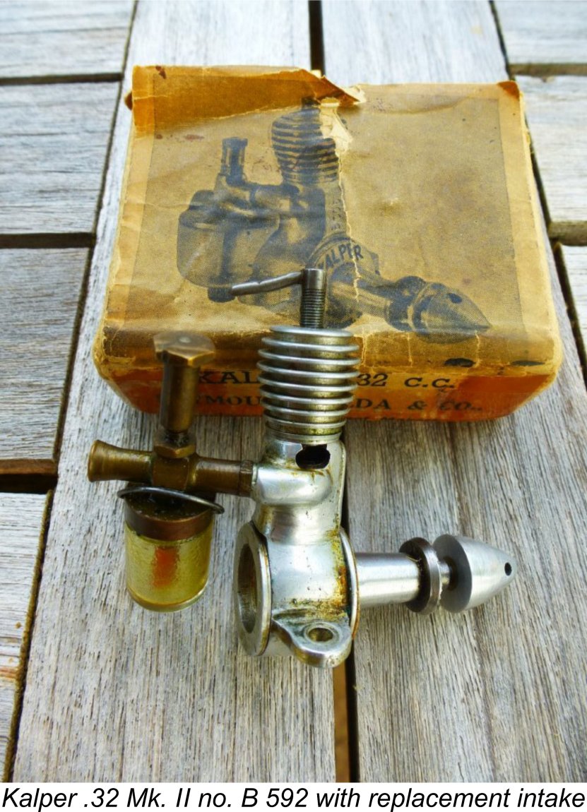 Following the initial appearance of this article on this website, I was contacted by reader Peter Wallis, who advised that he had owned Kalper .32 Mk. II no. B 592 for the previous 73 years, having bought it new from Roland Scott in 1950. It had served him very well indeed, but at some point early on suffered the misfortune of having the intake casting develop a fracture around the thread.
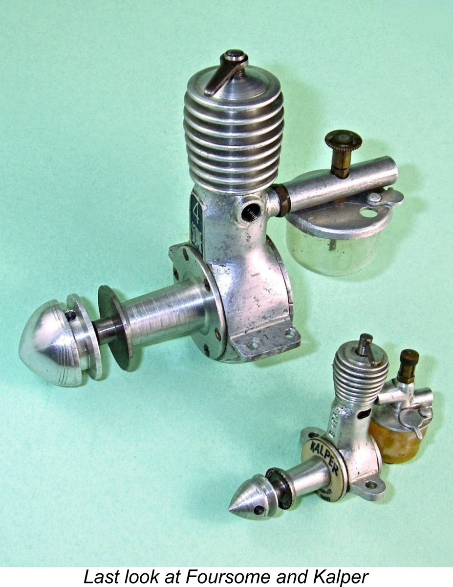
| |