
|
|
The Super Tigre G.30 Diesel Revisited
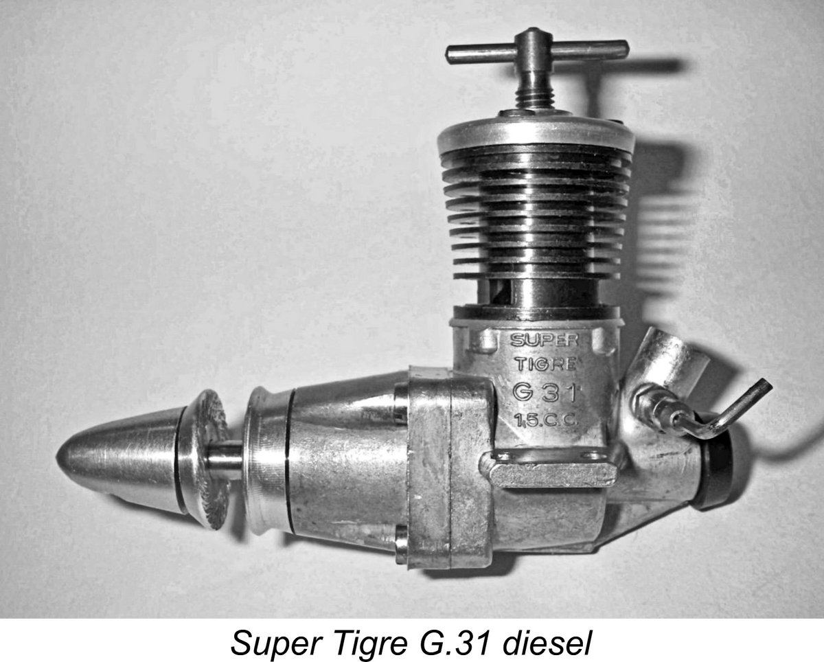
The G.30 was apparently developed to counter the incipient appearance of the rival Italian Barbini B.40 TR (Testa Rossa) crankshaft front rotary valve (FRV) diesel which made its debut in late 1956. The G.30's cylinder porting was actually a reflection of that employed in its Barbini rival (or vice versa), although the bypass passages in the Super Tigre were considerably larger. I've included the B.40 TR in my in-depth article on the Barbini range to be found elsewhere on this website.
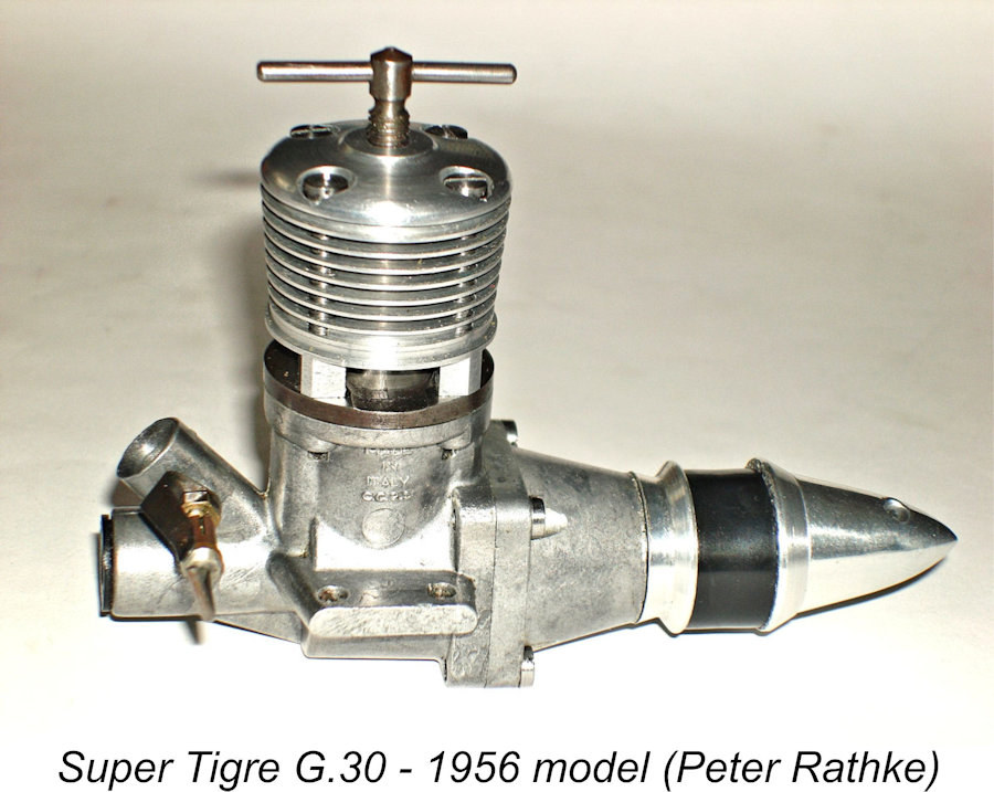
The truth appears to be that the G.30 actually did precede the G.31 in design terms, making a relatively low-profile debut in limited numbers in Italy during 1956, at which time it featured a plain un-anodized cooling jacket. Presumably these engines were viewed as test prototypes which were released without fanfare to certain Italian modellers in order to assess their competitiveness in the field. The design of the G.30 thus preceded that of the G.31, just as the numbers would suggest.
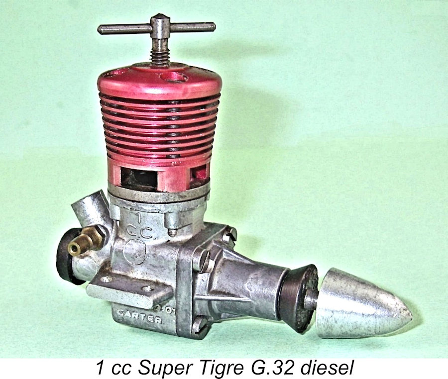
It actually appears likely that the 1956 G.30 test units had proved to be satisfactory. However, the release of the G.30 in production form was delayed while Garofali developed the design of the 1 cc G.32, which was in essence a scaled-down version of the 2.5 cc G.30. The two clearly-related models could thus be released more or less concurrently. The more familiar variant of the G.30 which finally appeared in October 1957 seems to have been externally identical to the 1956 model apart from the application of a red anodized finish to the cooling jacket. Of course, there may well have been internal modifications on the basis of experience gained with the 1956 units.
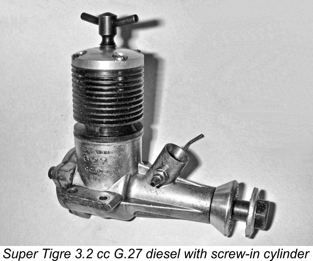
However, Chinn’s comment has never made much sense - there’s absolutely no underlying logic. The G.31 actually seems to embody a design progression or at least a side-step away from that of the G.30. While undeniably reflecting the G.30's crankshaft and drum valve arrangements, it reverts to a screw-in cylinder like the earlier Super Tigre diesel models but does away with the external bypass arrangements of the G.30 and its diesel predecessors in favour of two internally-milled bypass/transfer flutes exactly like those used in the contemporary Cox designs from America. It looks like an experiment to see if the G.30's cylinder construction could perhaps be simplified. This concept does not appear to have persuaded Garofali of its merits, because the G.31 was to prove to be the only Super Tigre diesel to be so equipped. The confusion over precedence evidently arose because Chinn was unaware of the fact that the G.30 had in fact materialized in Italy below the international radar during 1956, thus preceding the G.31 in design terms just as the numbering would suggest. Now, before I get to the testing of the G.30, a basic description appears to be in order. The Super Tigre G.30 Diesel - Description
Bore and stroke of the G.30 were the standard Continental 15 mm and 14 mm respectively for a displacement of 2.474 cc (0.1509 cuin.). The engine weighed in at a checked 179 gm (6.3 ounces) - a bit heavier than average for a competition diesel of this displacement, but not an unreasonable figure provided that the weight was put to good use. A lighter plain bearing “Sport” version of the G.30 was also produced in relatively small numbers, but it doesn’t seem to have been a sales success - examples are extremely rare today, at least outside Italy.
The blind-bored interior of the drum was open to the crankcase, with the induction port controlling entry into the interior of the drum from the base of the downdraft intake venturi. In effect this was a conventional crankshaft front rotary valve (FRV) arrangement relocated to the rear of the engine. There was a relatively short period of sub-piston induction to help things along – about 30 degrees in total, extending 15 degrees either side of top dead centre. So why use a drum valve at all? Why not just stick with FRV induction, thus avoiding the additional complexity, weight, length, friction and viscous drag of the rear drum? In fact, there are some very sound engineering reasons for adopting the drum valve design. Because the drum does not have to transmit the engine’s torque or absorb any reciprocating loadings, it experiences far lower stress levels than the shaft of a conventional FRV design. In addition, its outside diameter is not constrained by the inner diameter of the ball-races used to support the main crankshaft. Consequently, the designer is free to take far greater liberties in terms of drum diameter, internal gas passage diameter, induction port size and induction timing. Garofali took full advantage of this - the internal gas passage in the G.30's drum valve has a diameter of 7 mm, far larger than could have been safely accomodated by the engine's 8 mm diameter crankshaft and actually larger than the diameter of any contemporary FRV diesel. The drum has an outside diameter of 9.5 mm. Moreover, because the main crankshaft now plays no part in controlling the engine’s induction cycle, it can be left free from any induction port or gas passage, thus greatly enhancing its strength and fatigue resistance. The attached component view extracted from Peter Chinn's March 1958 test of the G.30 should help to make its construction clear to the reader. In purely functional terms, the cylinder porting of the G.30 was basically the same as that featured in Garofali’s earlier diesel designs from the G.23 of 1953 through to the G.29 of 1956. All of these previous models incorporated screw-in cylinders having two very large upwardly-angled transfer ports located between twin exhaust apertures, giving a very free-breathing form of reverse-flow scavenging. Basically this was the same system employed in the Cox and Holland engines from the USA.
This was in fact a direct copy of the bypass system used by Charles Brebeck of the USA in connection with his OK Cub models. Brebeck claimed patent protection for this system, but a review of the cited US Patent (no. 2179683) confirms that its application is sketchy at best. In any case, the difference between the transfer porting arrangements in the Super Tigre and OK designs would have been sufficient to forestall any charges of patent infringement, even if Brebeck’s US patent had any legal force in Italy. Unlike the earlier Super Tigre diesel models (and the subsequent G.31), the G.30 cylinder was not a screw-in component. Instead, it was retained through the use of a slip-on light alloy cooling jacket which was secured with four long machine screws. These screws passed through holes in the cylinder installation flange to engage with tapped holes in the upper crankcase casting. This arrangement ensured a fore-and-aft location for the upwardly-angled transfer ports to line up with the bypass passages, with the twin exhaust ports discharging one to each side.
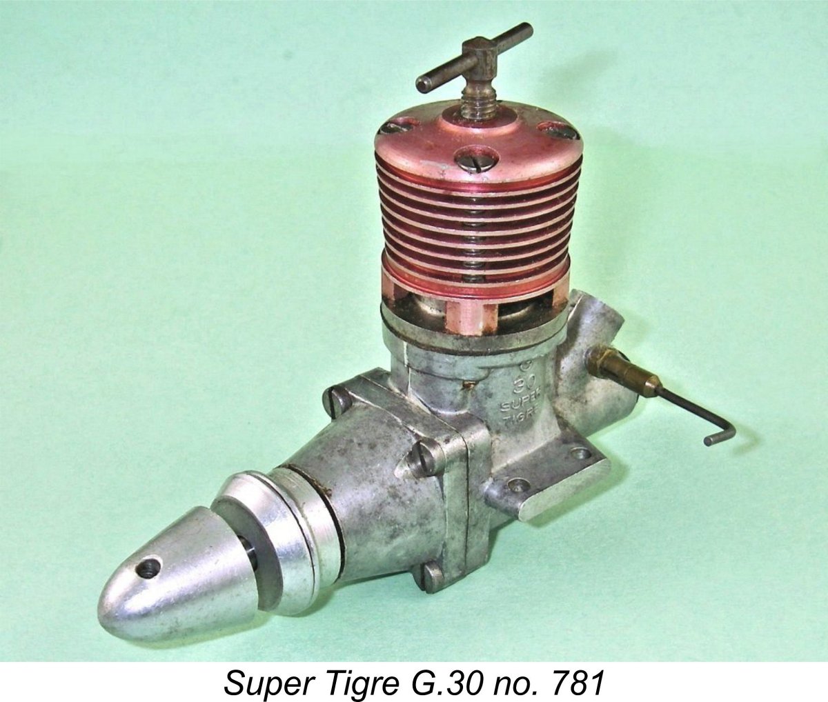
The obvious application of the G.30 was in FAI team racing, for which reason the undersides of the mounting lugs were very precisely machined parallel to ensure a perfectly secure mounting. The engine found its way into the noses of a number of FAI team race models in the late 1950’s, particularly in its native Italy, where it reportedly gave a good account of itself. However, it proved unable to oust the all-conquering Oliver Tiger from the top of the International results sheets, probably due to its higher fuel consumption. Despite this, it remained available until early 1960, after which it was replaced by the very successful G.20/15-D “Jubilee” diesel which was also included in my earlier Super Tigre article. Despite its seeming weight handicap, the G.30 did also see service in the free flight category. R. Guilloteau of France used the engine at the 1958 World Free Flight Championship meeting held at Cranfield in England. This event was unbelievably closely contested - no fewer that 41 of the 54 entrants scored at least 800 out of a possible 900 points. Among them was Guilloteau, who scored a very creditable 841 points using his Super Tigre G.30 diesel powerplant. However, this was only good enough for 36th place at this event! Before we dismiss this effort, it's important to note that Guilloteau scored maximum points (3 minutes - 180 seconds) in 4 of his 5 flights. It was only a problematic 2 min. 1 sec. 4th flight that kept him off the leaderboard. A very creditable effort indeed, and one which attests well to the performance of the G.30 in this event. Like most Super Tigre engines, the 1956 version of the G.30 did not bear a serial number. However, the 1957 red-head variant was one of the few Super Tigre models to which serial numbers were applied (the 1957 G.20 V glow-plug unit was another). My tested example bears the serial number 781, while that illustrated by Jim Dunkin in his invaluable “Reference Book of .15 ci / 2.5 cc Model Airplane Engines” bore the number 179. This implies that the numbering started at 001 and that at least 781 examples were made. Mine appears to be a relatively late example. Just to confuse this issue, I have a second complete and original red-headed example of the G.30 which formerly belonged to the late Mats Böhlin of Sweden. This example does not display a serial number. There appear to be three possibilities - one, some of the early models did receive red-anodized heads; two, this unit has an un-numbered spare-part crankcase; or three, some of the 1957 red-head examples did not receive serial numbers. At this distance in time, there's no way of knowing. Performance Questions Raised by Peter Chinn’s Original Test
However, reading between the lines, it would appear that the engine’s performance on test fell somewhat short of meeting Chinn’s expectations. He measured a peak output of 0.285 BHP at the unusually high speed (for a 1957 diesel) of 16,000 rpm. While he characterized this as being “a very good maximum figure”, he diplomatically refrained from pointing out that a number of other 2.5 cc competition diesels had comfortably exceeded this figure by early 1958. Chinn did his best for the manufacturer by citing the factory performance claim of 0.31 BHP @ 18,000 RPM, stating his doubtless sincere belief that such a figure might be achievable with “a good example working under favourable conditions”. Normally when I have a set of Peter Chinn’s generally dependable performance figures available, I see little point in conducting a re-test of the engine in question. However, in the case of the G.30, I was not comfortable in leaving things there. Looking objectively at the engine, there certainly seems to be a lot more performance potential in the design! Chinn himself seems to have agreed with this assessment - he was apparently somewhat taken aback by the lower-than-anticipated level of performance which he measured for the G.30. Could he have somehow got hold of a sub-standard example?
Laurie had purchased this particular G.30 new in the late 1950’s, being attracted by its out-of-the-rut design. Given the fact that he was an active team race competitor at that time, he almost certainly planned to use this example of the G.30 in a team racer, probably an example of his newly-designed and equally out-of-the-rut delta-winged Skyhawk of There is clear evidence to suggest that Laurie was quite serious in pursuing the best possible performance from the engine. Consideration of the G.30's steeply angled intake tract should convince the reader that the intersection of the round induction tract with the upper surface of the drum valve bearing necessarily produces a register opening in the upper bearing surface at the interface with the drum which is an extended elliptical shape. It would obviously be desirable to have the induction port in the drum valve present an elongated shape which overlaps that of the register opening in the bearing, thus eliminating the potential presence of a discontinuity in the induction tract. This being the case, an obvious weak point in the design of the Super Tigre G.30-D was the use of a simple round drilled hole to serve as the drum valve's induction port. Although it was drilled or milled at an angle, it still didn’t come close to conforming to the elongated shape of the matching register opening in the bearing surface. This mismatch created a significant discontinuity in the gas flow path into the crankcase. I must confess to feeling some surprise that a designer of the calibre of Jaures Garofali missed this point. Perhaps he was relying on his competition-minded customers to fine-tune this system.............
The result was a very large unobstructed interface area with extremely rapid opening and closing of the valve. It must surely be clear that this fairly simple modification could have a very positive effect upon the engine’s induction and hence its performance. This must be borne in mind when considering my own test results to be presented below. Peter Chinn mentioned the presence of small cutaways at the front and rear of the piston crown to aid in the direction of incoming gas upwards into the upper cylinder. These would of course have the negative effect of creating two peripheral pockets of “dead” mixture when the piston was at top dead centre around the ignition point – not a good feature. It’s noteworthy that my possibly later example (no. 781) does not have these pockets, the piston crown taking the form of a truncated cone. The truncation in combination with the conical underside of the contra piston would have the effect of creating a degree of squish effect in the combustion chamber near top dead centre. Perhaps this represents a design change after the first few hundred examples had been made?!? Be that as it may, the point here is that my engine differs from that tested by Chinn in several respects which could have a positive effect upon the performance of my example. The intake diameter of my engine is a generous 6.5 mm, with a 3 mm spraybar traversing the venturi. I have no idea how these figures compare with Chinn’s example, since he did not provide these dimensions in his test report. All that I can say is that they appear to be perfectly reasonable. Maris Dislers' invaluable choke area calculator gives an effective choke area of 14.399 mm2, with a minimum effective operating speed on suction fuel feed of just under 12,000 rpm in a contest application. Since the engine appears to peak in the vicinity of 16,000 rpm (as claimed by the manufacturer), that doesn't represent an issue if the engine is to be used in competition. An Earlier Test
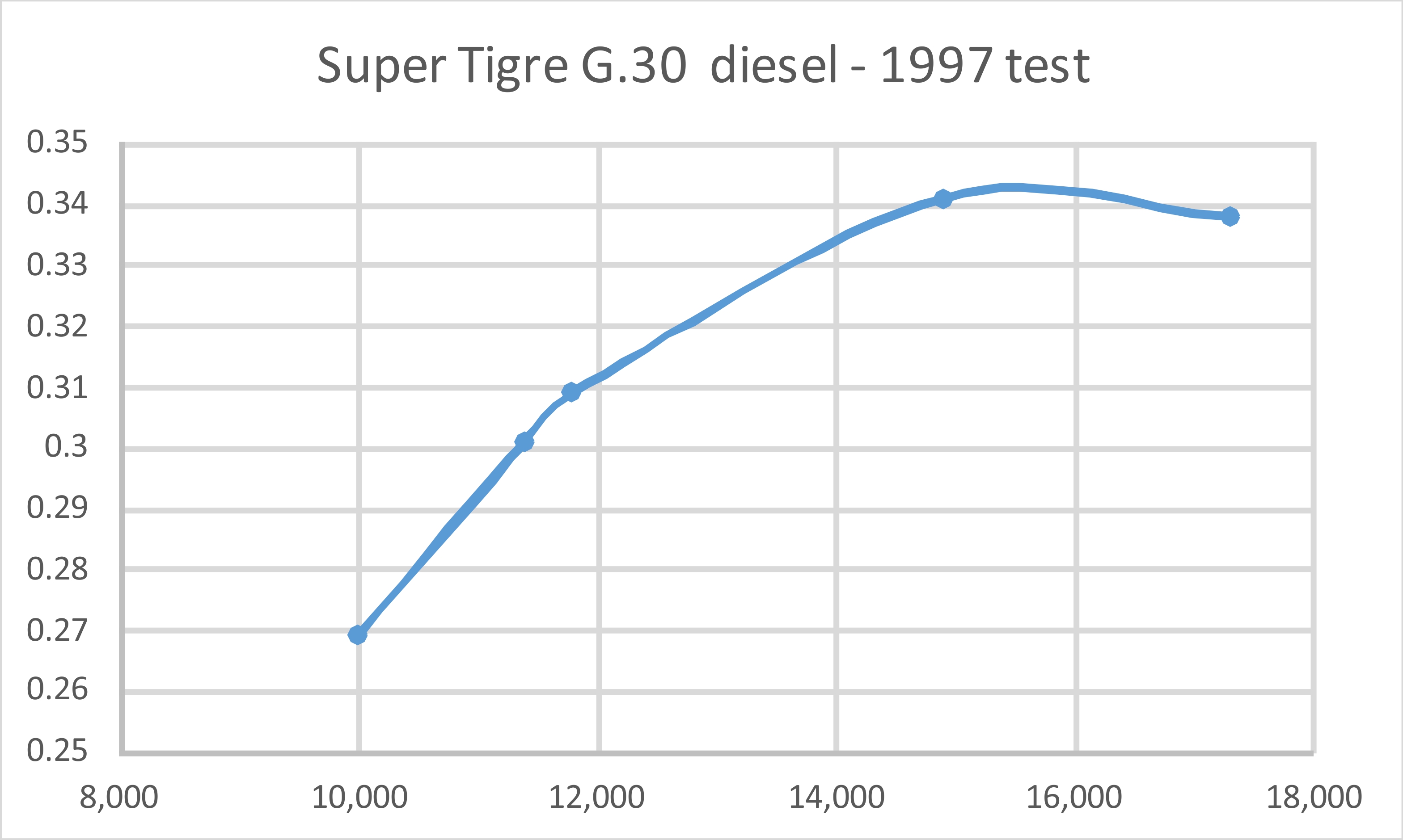
I was very mindful of the fact that the rpm figures which I recorded back then were obtained using my old Heathkit Thumbtach analog device – I hadn’t yet graduated to the digital devices which I’ve used since about 1999. Hence there’s no doubt at all that these readings could well be a little off, although my still-functional Thumbtach continues to give figures which are very close to those measured using a modern digital device. I was also using an old set of Taipan props which I had lying around at the time. My calibration figures for Taipan props may or may not be precisely applicable to those particular airscrews. Finally, I failed to record the fuel composition used for these tests. It was probably a mixture of 40-30-28-2 parts of kerosene, ether, castor oil and ignition improver which I generally used at that time for testing (and still do on many occasions). Regardless of these potential shortcomings, I did record the measured speeds for a number of props, as follows:
It’s clear that I was missing a few props between the 8x6 and 8x4, since there’s a glaring gap in the data between those speeds. The same comment applies to the large gap between the 8x4 and 7x4 props. Even so, the data appears to be internally consistent, with the implied peak evidently lying somewhere between 14,900 RPM (when output was still on its way up) and 17,300 RPM (when it was presumably on the way down). A figure of around 0.347 BHP @ 16,100 RPM seems to be a reasonable guestimate. This is a very creditable finding which may not be absolutely accurate but which is unlikely to be all that far out. Note that the implied peaking speed matches Chinn’s results, but my tested example appears to have developed considerably greater torque. Despite their stated limitations, the above figures seem to make it abundantly clear that my example runs far more strongly than the one tested by Peter Chinn. Indeed, it’s noteworthy that the implied power output represents a significantly higher level of performance than that claimed by the manufacturer. This may well be the result of the former owner’s well thought-out modification to the drum valve. Whatever the truth, these old figures cannot be claimed as necessarily representative. To settle the matter once and for all, it was clearly necessary to run a complete present-day re-test of the engine using my current suite of calibrated test airscrews along with a digital tachometer. The Super Tigre G.30 on Present-Day Test For this test I brewed up a fresh batch of the same blend that I probably used for the earlier test. This consisted of 40% kerosene, 30% ether, 28% castor oil and 2% ignition improver. Past experience with many test engines has demonstrated that this brew runs very well while at the same time being very kind to the engines’ wearing surfaces. No doubt a blend with less oil and more kerosene would deliver a little more power, but I didn’t want to push this rather rare engine unduly or subject it to additional wear.
I soon found that starting wasn't this engine's strong point. Choking alone didn't get enough fuel up into the combustion chamber - the engine required a prime to start. This was almost certainly due to the very large size of the bypass passages and transfer ports, which would result in very low transfer gas velocities at flick-over speeds. However, once a prime was administered, a start was quickly achieved. Before anyone condemns the engine as a non-starter in team race applications, it's important to remember that team race motors are almost invariably mounted in the inverted position. With such a mounting, gravity would ensure that fuel reached the combustion chamber without priming. I'd be prepared to bet that this engine would be a very good prime-less starter when inverted - just what you need in a team race engine. Once running, I quickly found that the contra piston in this example was fitted just a little too tightly - getting it to run back to reduce compression during warm-up took a few "quick chokes" (a dab of the finger over the intake to momentarily richen the mixture). Oddly enough, things settled down nicely once the engine was fully up to temperature, allowing easy adjustment on the run. Response to both controls was very positive, allowing optimum settings to be established very easily for each run. Both controls held their settings dependably. Once set, the engine ran completely smoothly at all speeds tested, also exhibiting very low levels of vibration. As a result of these excellent running characteristics, this test became a real pleasure (although perhaps not for the neighbours!). The following data were obtained:
The two WB props are cut-down APC airscrews created to fill gaps in the range of power absorption coefficients represented by my standard test set.
It's interesting to note that Laurie Ellis's tuning operations didn't extend the engine's peaking speed - rather, the modified engine develops more torque over the same range of speeds. Consequently, the peaking speed is actually down a little from Chinn's figures, but the peak power is considerably greater. With an engine having this purpose, I'll take torque over speed any day! A standard team race prop back in the late 1950's would probably have been a 7x8 or 7x9. On the basis of this test the engine would probably do a pretty fair job of turning team race props of either size. For general-purpose control line applications, a "fast" 8x6 would likely be quite suitable, while an 8x4 would work very well for free flight. All in all, a stellar performance from an engine of real quality! Just for fun, I also tried my other example of the G.30 - the unnumbered and seemingly unmodified example formerly owned by Mats Böhlin. This example started and ran every bit as well as its tuned companion, but was some 400-500 rpm down on props in the vicinity of the peak. It appears that Laurie Ellis's tuning efforts were quite effective! Conclusion
There appear to have been only two chinks in the G.30’s armour. First, it was a little heavier than most of its then-current competitors. Secondly, it seems to have had a somewhat higher rate of fuel consumption than others such as the Oliver Tiger. The first of these issues might have told against it in free flight service, but that was not its primary intended application anyway. The higher fuel consumption was probably its most significant handicap for its primary intended application in team racing. Even so, the G.30 represented a bold, innovative and largely successful attempt by Jaures Garofali to create a 2.5 cc competition diesel of real merit and distinction. If you ever get the chance, this is an engine which is well worth experiencing!! ___________________ Article © Adrian C. Duncan, Coquitlam, British Columbia, Canada First published September 2023
|
||

 The fact that the smaller G.31 somehow arrived on the worldwide market well in advance of its big brother led
 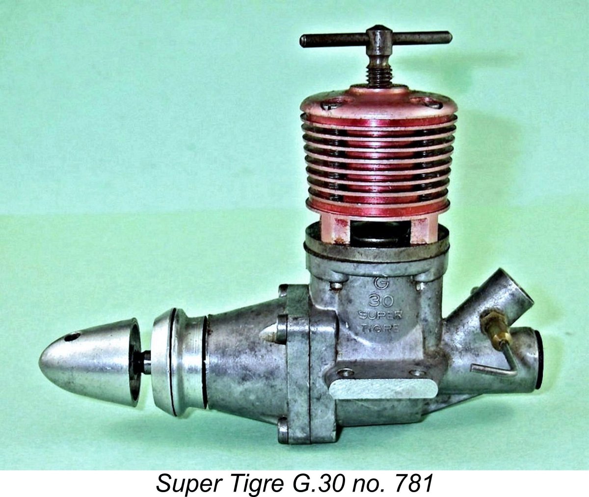 The Super Tigre G.30 diesel was a relatively advanced design featuring a twin ball-race crankshaft, well-developed cylinder porting and a rear drum rotary valve. It was notable as being the first ball-race diesel to be released under the Super Tigre banner since the diesel version of the 4.82 cc G.19 which had been the very first Super Tigre by that brand name back in 1949.
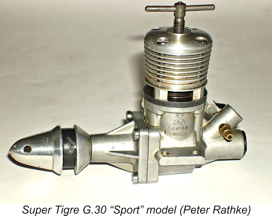 A drum valve of generally similar design to that used on both the G.30 and G.31 diesels had first been utilized by Garofali in his very powerful 10 cc
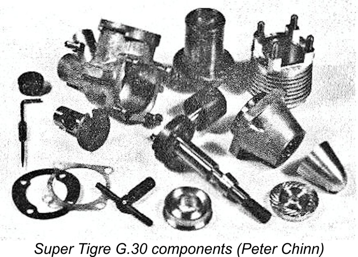
 The transfer ports passed through the cylinder wall to align with very large external bypass passages formed in the crankcase at the fore and aft locations. To avoid fouling these ports, the gudgeon (wrist) pin was retained by a pair of tiny circlips located at the outer ends of the pin’s installation holes in the piston bosses. If you acquire an example of this engine, it's well worth checking to ensure that these clips are in place, otherwise serious damage can result from any attempt to run the unit.
  As was so often the case, the ever-informative
 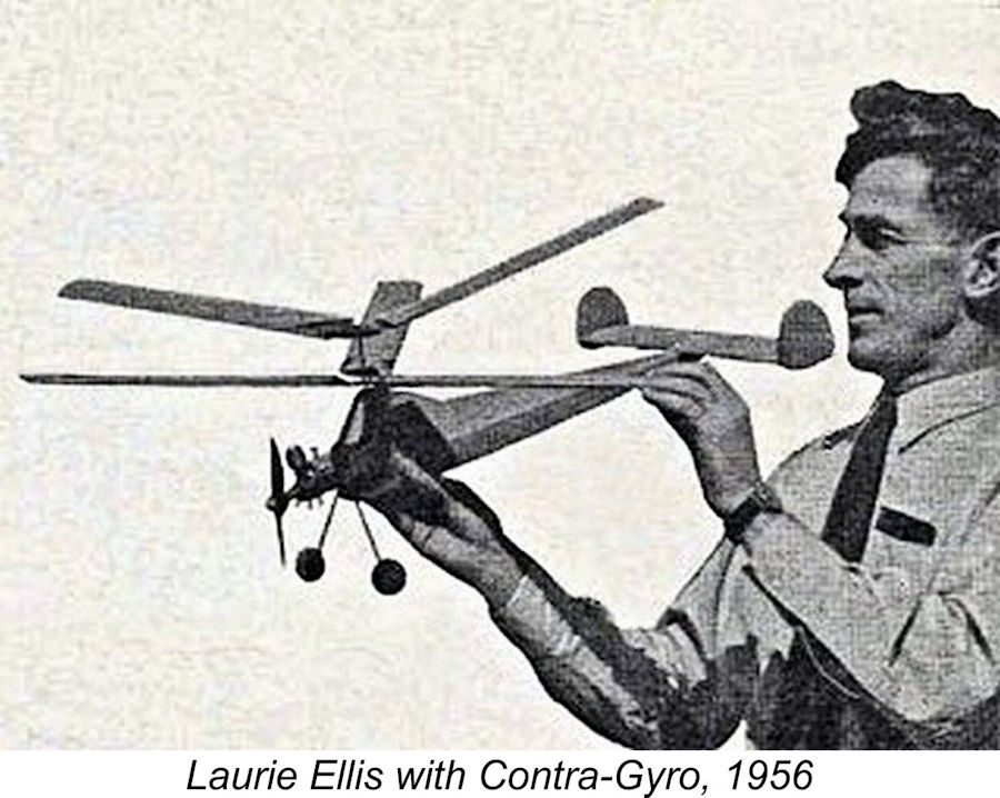 I’m only the second owner of my own example of the engine (s/n 781) in its 65 year lifetime. The engine was obtained decades ago from its original owner, my late Canadian friend RCAF Squadron Leader Laurie Ellis, D.F.C. Laurie was a very well-known modeller both in Britain and Canada in the 1950's and early 1960's with a sizeable number of published designs to his credit (anyone else remember the Vultan, Javelan, Skyhawk and Contra-Gyro among numerous others?!?). After returning to Canada in the mid 1950's from long-term overseas service in Britain both during and following WW2, he operated the Academy Model Supply Co. business in Toronto for a number of years.
 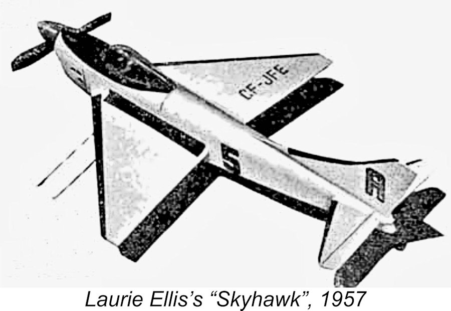 1957. Laurie used his trusty Mk. III Oliver Tiger in the original model, evidently never trying a switch to the G.30. The absence of witness marks on the lugs suggests that the engine was never actually mounted in a model of any sort, although it had clearly done quite a bit of bench running.
 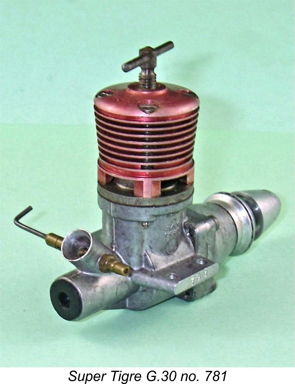 If so, Laurie Ellis didn't disappoint him! Laurie was an accomplished engine tuner who undoubtedly saw what was going on. In response, he (or someone working to his direction) had taken steps to re-configure the drum valve’s induction port to give it an elongated fore-and-aft shape which slightly overlapped that of the matching register opening at the base of the intake. This was accomplished by extending the port in an axial direction, creating a slightly extended port of "race track" shape which matched the elliptical shape of the crankcase register opening far better. The induction timing was left unaltered. Laurie did the same thing to his G.31 and G.32 engines which I also acquired from him at the same time.
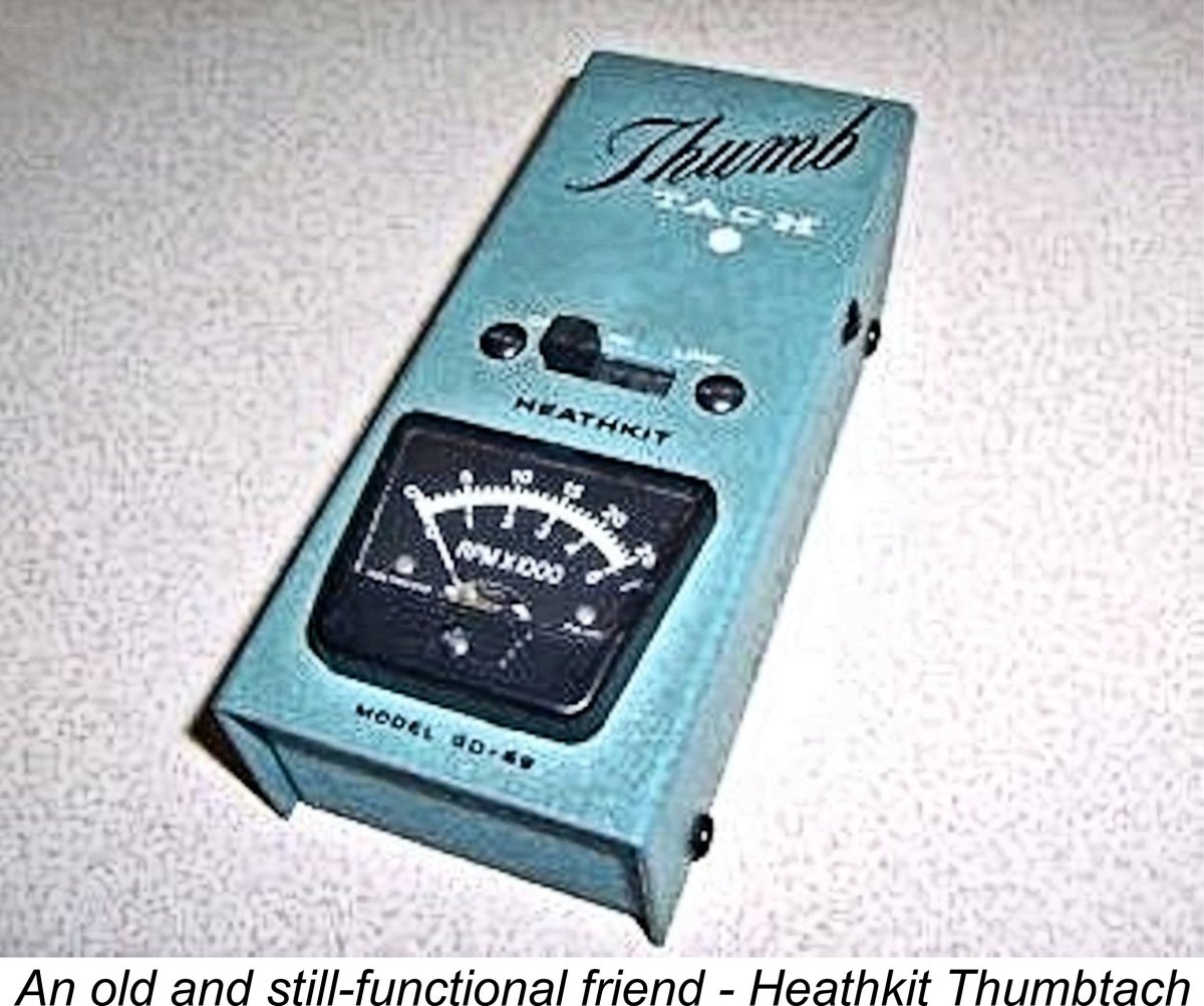
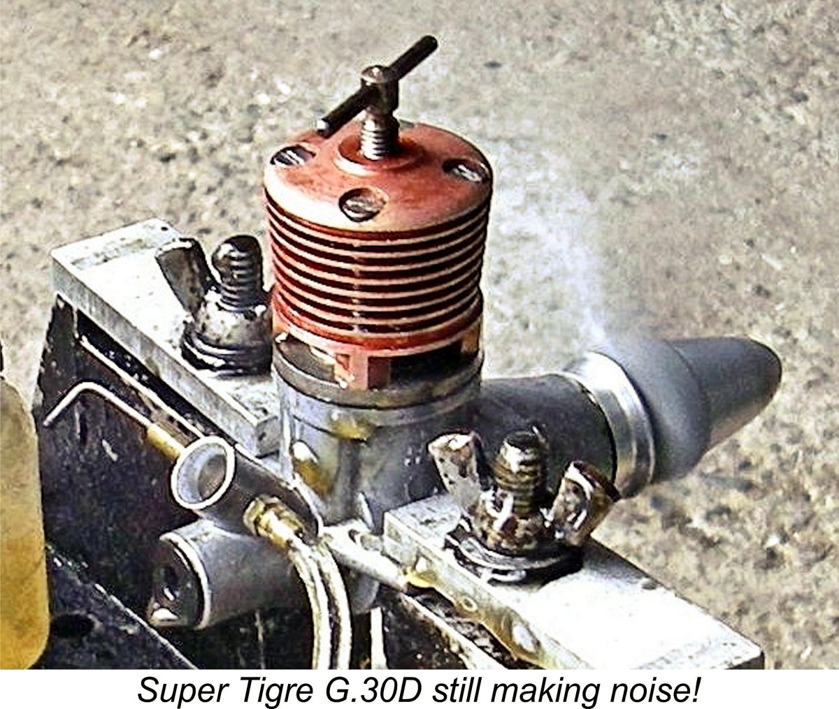
 Mounted in the test stand, the Super Tigre felt absolutely superb - no sign of the dreaded stiction around top dead centre, but a perfect compression seal. The rod bearings displayed no detectable play either, while the ball races felt silky-smooth. The engine was clearly all ready to go!
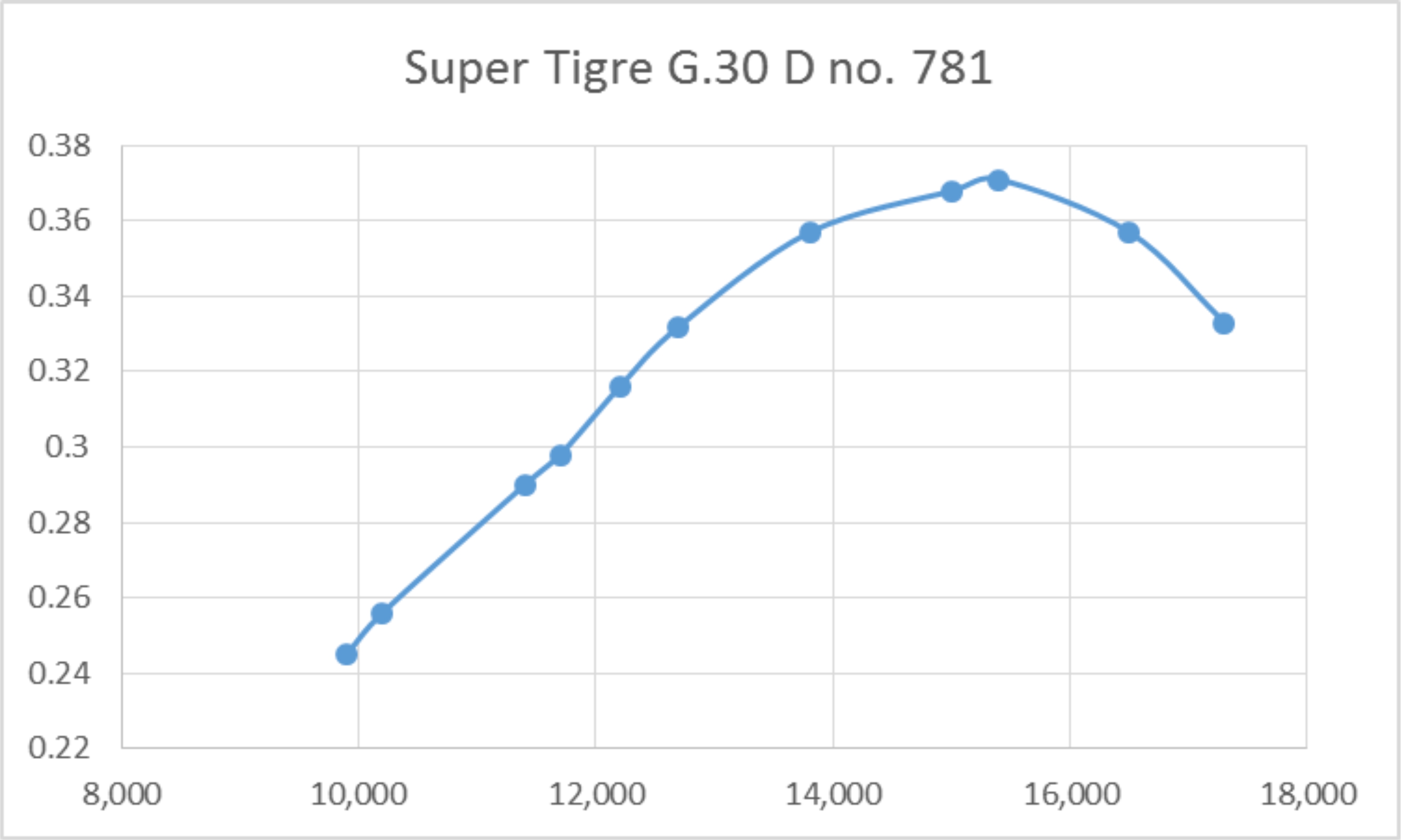
 As the above figures show, the G.30 appears to have run even better on this occasion than it did back in 1997! The above figures don't flatter the engine in any way - I'd be happy to repeat them for any skepic who comes calling! The implied output is a most impressive 0.372 BHP @ 15,400 rpm. Very few if any contemporary series-production 2.5 cc diesels could match or even approach these figures. The only classic 2.5 cc diesel which has achieved a higher output during one of my tests is the much-modified
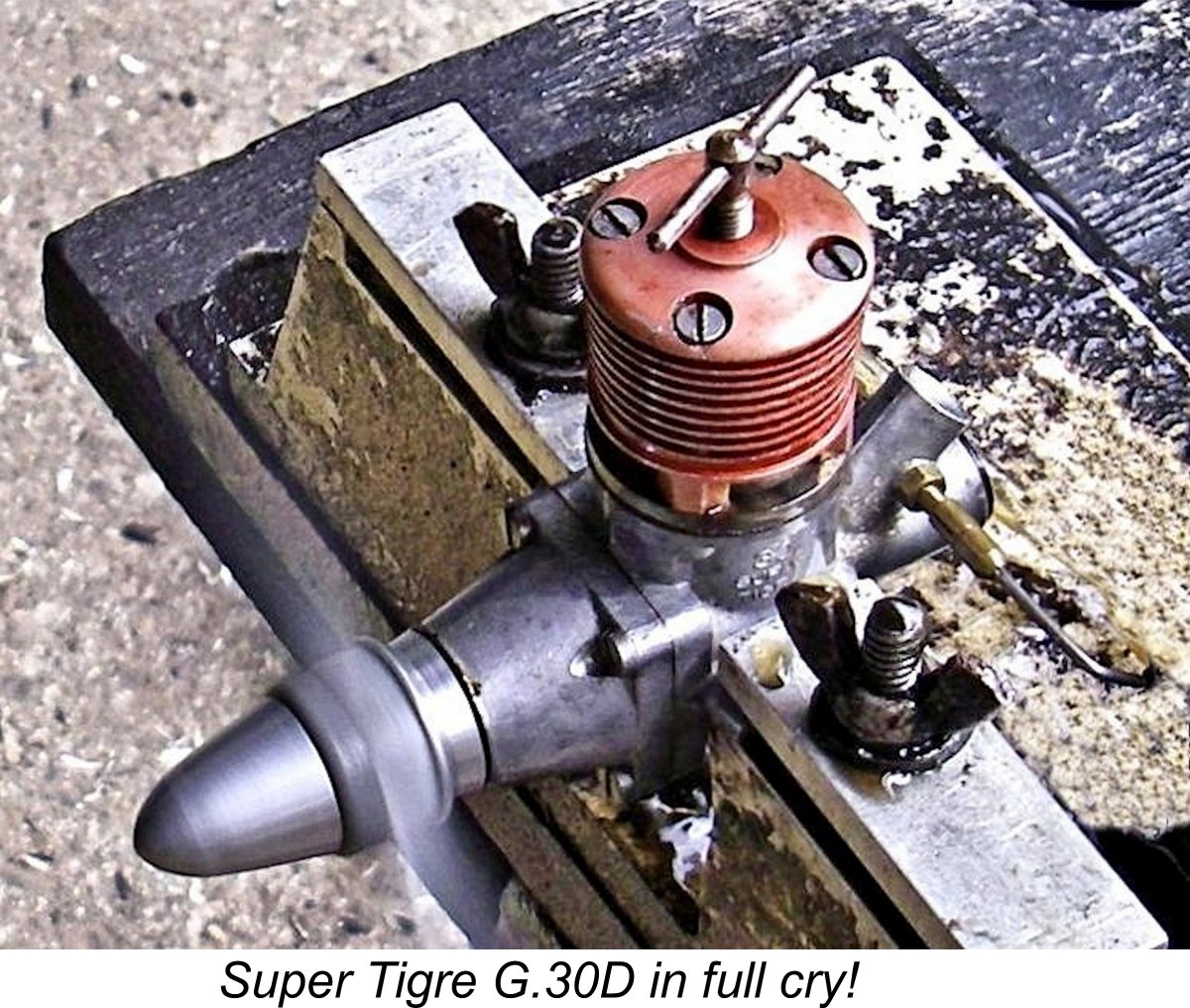
 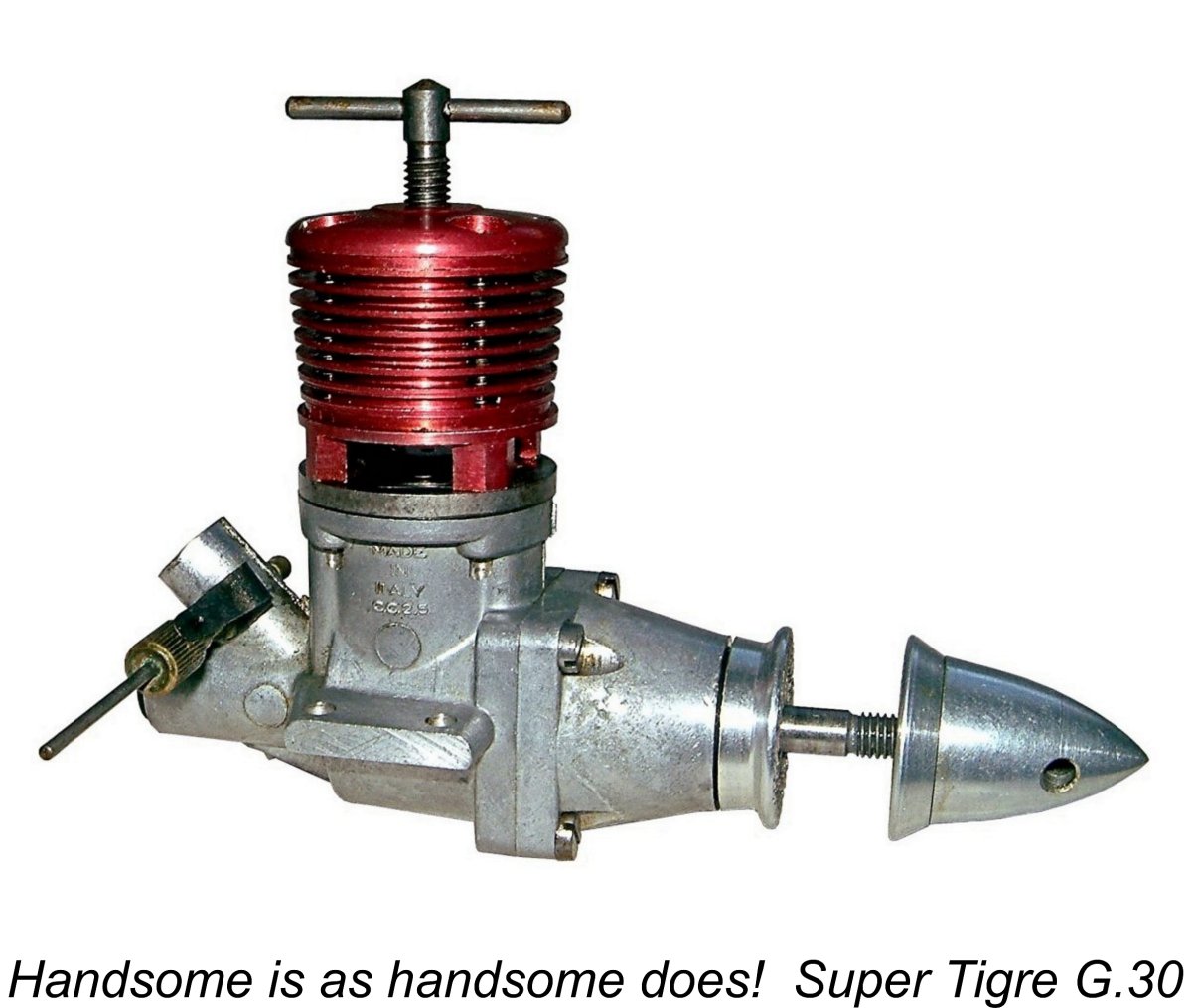 Well, there you have it! There can be little doubt that a well-prepared example of the Super Tigre G.30 diesel was indeed a “world class” model power unit as categorized by Peter Chinn. By 1957 standards it was unquestionably at or very near the top of the performance heap, especially when competently prepared. It was also an extremely well-made and fine-handling unit which was undoubtedly able to give long and faithful service to any owner.
 | |