
|
|
Swedish Rarities - the Pinotti GP Engines
Among the many interesting inclusions in the text was a comprehensive international survey of then-current commercial model diesel engines. Considering the early date of this publication, only a little over a year after the conclusion of WW2, the number of such engines included in this survey was actually quite remarkable, reflecting very rapid growth in the early post-war development, manufacture and marketing of these products. This being the case, it may seem strange to many readers to learn that only four of the 50 (!!) models included in this survey originated in Britain! Although Britain was later to become a world leader in model diesel development and manufacture, the exigencies of the recently-concluded war had left that country lagging far behind those European nations in which model diesel experimenters had had the opportunity to gain a head start as a result of their homelands remaining neutral; spending much of the war in a state of occupation; or being eliminated from the conflict prior to the conclusion of the war elsewhere by the rising tide of Allied military success. One of the countries which had managed both to maintain a state of neutrality throughout the war and to escape military occupation by one of the belligerents was Sweden. Consequently, modelling activity in that country was continuous throughout the war years, including some early investigations into the model diesel concept. A very limited amount of information regarding wartime model diesel development in Sweden had somehow filtered through to Laidlaw-Dickson, who included a very brief commentary on then-known model diesels of Swedish origin. However, this section was very brief indeed - the only two Swedish maker’s names which had come to the attention of Laidlaw-Dickson as of mid 1946 were those of Rogstadius and Pinotti.
Thanks to some splendid and (as it turned out) timely work by my valued Swedish friend and colleague Lars Gustafsson, it was possible to arrange for a 2009 interview with Ivan Rogstadius (since deceased), a summary of which may be found here on Ron Chernich’s “Model Engine News” (MEN) web-site. As a result of this contact, the Rogstadius story was fully documented as of 2009, and not a moment too soon. However, the same could not be said for Pinotti, that mysterious Swede with an Italian name! All that Laidlaw-Dickson had been able to tell his readers in late 1946 was that Pinotti was “an Italian who emigrated to Sweden” and that his engines followed the general pattern of the Dyno in design terms. They were reportedly identified by the trade-name CP. A few basic technical details (which subsequently proved to be generally accurate) were provided in the Appendices along with the manufacturer's recommended fuel mixture, but that was about it. There the matter rested until the March 2010 appearance of Ulf Carlén’s outstanding English-language book "Swedish Model Engine Encyclopedia". This excellent and highly recommended work included a complete section on the engines manufactured by one Giancarlo Pinotti – clearly the individual mentioned by Laidlaw-Dickson. Little information was provided on Pinotti himself, but the engines that he produced between 1938 and 1950 were covered in some detail. I freely acknowledge having made frequent reference to this work while developing the present article, with my very sincere thanks to Ulf for making the information readily available. This seemed to complete the documentation of the pioneering Swedish model diesels mentioned by Laidlaw-Dickson in his 1946 book, at least in the English language. However, as events proved, this was by no means the end of my own involvement with the Pinotti engines! There’s always more to be learned – the trick is to recognize and sieze any opportunity to add to one's knowledge.
Although it's sometimes not possible, my preference has always been to structure my historical articles around the examination of at least one actual example of a given maker’s work. Here was another opportunity to do just that! I authorized Lars to bid on my behalf, which he did most competently. Others had obviously recognized the engine and appreciated its significance and rarity, resulting in stiff competition for its acquisition. However, Lars was able to acquire it for me in the end. In doing so, he also acquired the two Mills replicas which went with the Pinotti. I restored those engines to excellent condition for re-sale following succesful tests, thus sweetening the deal somewhat.
As a result of Kjell's kindness and skill, my new acquisition was soon I'm also greatly indebted to well-known Swedish collector Sten Persson, who kindly sent along some very informative images as well as providing information to Kjell regarding replica parts. While all this was going on, Lars Gustafsson had not been idle. Following further interactions with Ulf Carlén, whose co-operation in this regard is also greatly appreciated, he was able to provide me with English translations of a number of key Swedish-language As if this wasn't enough, Lars also took the trouble to track down Michael Pinotti, the grandson of Giancarlo Pinotti. Michael was very supportive of our efforts to recognize the achievements of his grandfather, whose memory he clearly held in great affection. Not only did Michael provide us with all the assistance in his power, but he also encouraged other Pinotti descendants, including Michael's brother Janne, sister Eva and Italian cousin Vittorio, to share their recollections. Most of the personal information about Carlo and Mario Pinotti was supplied by these individuals. I'm very grateful to Michael and the other Pinotti family members for their kindness in this regard. Thanks to the assistance of all of the individuals named above, I eventually found myself in a position to share the full details of the Pinotti story with my English-speaking readers throughout the world. In undertaking this task, I wish to make it clear that I could have accomplished none of it without the help of Lars, Kjell, Ulf, Michael, Janne, Eva, Vittorio, Sten and of course Ulla. This article is their work as much as mine - I merely held the pen! Thanks, folks!! Now, on with our tale............. The Pinotti Story – the Pre-War Years
The basic genealogical information resulting from Ulla Gustafsson’s much-appreciated efforts included the fact that Giancarlo Marino Pinotti was born in Italy on January 23rd, 1900. His grand-daughter Eva Pinotti-Lindqvist has confirmed that his actual birthplace was Pizzighettone, a small town of some 7,000 present-day inhabitants which is located in the central Po River valley in the Northern Italian province of Lombardy near Cremona. We have few details regarding Pinotti's family background and early life in Italy beyond the bare facts that he was trained as an electrical engineer and that he also became a skilled musician along the way. The latter preoccupation is scarcely surprising given the rich musical heritage of the Cremona area. Michael Pinotti tells us that Giancarlo played piano, violin and baritone saxophone. He also became a skilled violin-maker, thus following in the footsteps of such celebrated Cremona artisans as Giuseppe Guarneri, Antonio Stradavari and Nicola Amati. Janne Pinotti recalls having been told that the genesis of Giancarlo Pinotti's relocation to Sweden arose directly from his musical associations. Apparently Giancarlo and a number of his musical friends soon found that they could make more money playing music together than they could following the professions for which they had been trained! One day while they were playing on the Italian Riviera, a visitor from Sweden heard them and asked if they would be willing to come to Sweden to play at his hotel and restaurant in Gothenborg. He offered them a cash advance along with the necessary tickets. They accepted this offer, travelling to Sweden in 1926 in a journey which ended up taking two weeks. Pinotti soon met his future wife Ella Viola, who was a native of Gothenburg. Michael Pinotti has shared a vignette regarding this period which in my opinion sheds a great deal of very positive light upon the strength of character of both Giancarlo Pinotti and Ella Viola. It seems that this was a case of true love at first sight, since Ella was immediately stricken with a very strong affection for the dashing and multi-talented Italian immigrant who had swept her off her feet. Her feelings were very strongly reciprocated. However, when she told her parents that she had met an Italian to whom she was very much attracted, they forbade her to see him again! Ella responded to this parental edict in the traditional manner by running away from home with her Italian swain! Clearly, true love would not be denied! Michael Pinotti's sister Eva recalls being told that the couple immediately got married in Sweden, after which they returned to Italy, where they settled in Milan. They were married there for a second time in a Catholic church in 1927. The couple wasted no time in starting a family - their son Gianmario (of whom we shall hear a great deal more in this story) was born in Milan on April 17th, 1928. As matters turned out, Ella was not comfortable living in Italy. In all likelihood, this had much to do with the increasingly intrusive and militaristic Fascist regime led by Benito Mussolini which was eventually to drag Italy into a major armed conflict (WW2) which most of its citizens did not want. Be that as it may, the couple returned to Sweden in 1930. They were to spend the rest of their long married life together in that country.
Malmö was a major industrial centre with one of the world’s largest shipyards, the Kockums shipyard, being located there along with a range of textile and mechanical manufacturing industries. By the time of which we are speaking, Malmö had grown into Sweden’s third-largest city behind Gothenburg and Stockholm, with a population of well over 100,000 individuals. It's perhaps possible that Pinotti entertained ideas of re-entering the electrical engineering profession to support his family. This would explain his choice of the industrial centre of Malmö as a place to live. However, his musical career continued to blossom, to the point where he effectively set aside any ideas of returning to electrical engineering (if he ever had any such ideas!) in favor of remaining a professional musician. Initially he played in prominent classical orchestras, touring Sweden in this capacity for some years. However, this did not last, presumably in part as a result of the Great Depression, the effects of which, although relatively mild in Sweden by comparison with many other countries, were unevenly distributed across the country, with some areas being hit very hard. In the end, Pinotti found himself once again reduced (as he saw it) to becoming a ”restaurant musician”. Since he had rather lost touch with his original profession of electrical engineering, he was forced to support himself and his family in this manner. Thanks to the joint kindness of Ulf Carlén and Lars Gustafsson, I have an English translation of a most informative article about Pinotti from an un-named and un-dated newspaper which throws a great deal of light upon this period of Pinotti’s life. The context of the article makes it clear that it dates from the late 1930’s, probably 1939. The text was re-published (in Swedish, naturally!) in issue 2 of the magazine ”Oldtimer” for 2011. Big thanks to Lars Gustafsson for the translation!
Of greater relevance to our central theme of model engines is the fact that Pinotti had a fully-equipped machine shop in his basement, which was reported to be ”crowded with lathes and other delicate precision tools and equipment”. At the time when the article was written (most likely 1939), he had already commenced the construction of model engines using this equipment. A machine for the manufacture of spark ignition coils reportedly occupied a corner of the kitchen! Apparently Ella Pinotti used this equipment to wind the coils, thus contributing materially to the family venture. The writer of the article questioned Pinotti regarding the seemingly strange mixture of interests (music, art, cooking and precision engineering) which occupied the bulk of his time. Pinotti's response was that in fact there was nothing at all strange about a musician and artist working in the precision engineering field, especially not someone from Italy where a natural aptitude for both art and technology were often combined. As a musician and actor myself with strong mechanical leanings, a machine shop in my own basement and models hanging on the walls, I’m in complete sympathy with Pinotti on this one! One interesting fact which emerged from this article was the fact that by this time Pinotti was referring to himself as Carlo Pinotti rather than Giancarlo. According to his grandson Michael, he did so for the rest of his life. Presumably he felt that Giancarlo was simply too much of a mouthful for most people to deal with! The Swedish records turned up during Ulla Gustafsson’s research invariably refer to him as Carlo. By the same token, his son Gianmario (Michael Pinotti's father) was always known from this point onwards as just plain Mario. That said, there is ample evidence in the form of the trade name attached to his commercial model engines that Pinotti remained very proud of his Italian heritage and of his true given name. The initials GP were applied to the engines almost from the outset, clearly standing for Giancarlo (and for that matter Gianmario) Pinotti. Despite this, there’s no doubt that Carlo and Mario are the names by which both father and son normally referred to themselves and are accordingly best remembered. I will refer to them in this manner for the balance of this article. The Early Pinotti Engines
Pinotti’s self-acknowledged response to this unhappy state of affairs was to escape by immersing himself in one of his other interests, namely model engineering. Although he himself referred to this as a “hobby”, there’s no doubt at all that he approached it in a completely professional manner. He had begun by setting up the basement machine shop to which reference has already been made. Apart from his model engineering activities, there seems to be little doubt that Pinotti was also a keen model aircraft enthusiast. It was presumably this interest that led him to focus his attention upon the design and At this point, it's important for context to recognize the fact that Pinotti appears to have been the first Swedish resident to enter the field of commercial model engine manufacture. A close review of the contents of Ulf Carlén’s invaluable "Swedish Model Engine Encyclopedia" confirms that as of 1938 no other Swedish manufacturer had yet begun to produce model engines on a commercial basis. A few examples of engines from elsewhere, including the odd Brown and Ohlsson from America, had somehow found their way to Sweden, forming the basis for an emerging Swedish power modelling scene. A few engines were doubtless also constructed in Sweden on a one-off basis for the personal use of their creators. However, Pinotti seems to have been the first Swedish manufacturer to engage in the commercial series production of model engines, albeit on a very small scale. Once Pinotti had developed and tested a model engine design which he felt merited commercial exploitation, he looked around for an outlet through which the engines that he produced could be sold. His initial idea seems to have been to export his engines back to his native Italy, to which end he apparently entered into discussions with an Italian model goods company. In support of this ambition, the early examples of the engines made by Pinotti were designated as “Avio Minima” (Miniature Aviation) designs, although they nonetheless bore the GP (or in some instances JP) initials to identify their maker. His first engine, the Avio Minima JP 7.5 cc model, began to appear in very small numbers in 1938.
Pinotti was soon successful in finding a suitable outlet in the shape of the newly-established hobby shop at Storgatan 25 in Malmö run by Sven E. Truedsson (1919 - 1991), a famous free-flight exponent of the day and later founder of the well-known SEMO model kit company. Truedsson and his SEMO trade-mark logo are seen at the right. Soon after this development, the Avio Minima name faded into the background, the engines subsequently being identified simply by the manufacturer’s initials GP, or in the case of a few examples by the initials JP. The association of the JP initials with a few of these engines seems to beg an explanation of some sort. These initials appear to have been attached predominantly to earlier examples of the engines manufactured by Pinotti. This seeming anomaly might perhaps be best explained if we consider the strong possibility that some of Giancarlo's Swedish friends may have shortened his name to Gian, rendering it not unnaturally in its Swedish form of Jan or Janne. Pinotti may have gone along with this at least for a while, hence those early JP initials. However, if this was the case it didn't last - Pinotti clearly wished to acknowledge his true Italian name along with his Italian heritage, switching back at an early stage to his baptismal initials of GP. As far as I'm aware, the JP initials were never attached to any of the diesel models which began to appear in 1943. Although then not yet a teenager, Carlo Pinotti’s son Mario was already assisting his father in the manufacture of the GP (or JP) engines. Mario was later to recall that he and his father could only produce one complete engine per week at best. His mother Ella manufactured the ignition coils using the machine in the family kitchen.
In any event, the quality of the engines' internal construction more than makes up for any lack of "eye appeal"! These units were manufactured to very high standards of precision indeed, each one being virtually an individually hand-built tool-room product. During the early period of production, Pinotti went so far as to number every individual major component of each engine that he produced - an almost unprecendented level of attention to individual detail! He appears to have abandoned this practise at a later date - my own examples (of which more below) are un-numbered.
Like almost all pre-war spark ignition engines, the plug was a standard 3/8 -24 item, which was to be retained in all variants of this motor. An open-frame timer of conventional form was employed. On this early variant, the timer was mounted in a transverse orientation, in contrast to the less vulnerable axial orientation seen on later versions of the engine. The cylinder with its integral cooling fins was machined from a rather heavy iron casting which was attached to the crankcase using four bolts which passed through a location flange at the cylinder base to engage with tapped holes in a corresponding location flange cast into the upper crankcase. This material selection The initials JP or GP are cast in relief onto the bypass covers which seal the otherwise-open GHQ-style bypass passages. Those passages are supplied through a port cut in the lower piston skirt. Hopefully the attached image of a bypass with the cover removed at Bottom Dead Centre (BDC) will make this arrangement clear. The "deluxe" version of the engine as illustrated above weighs a reported 290 gm (10.23 ounces) minus accessories. Sincere thanks are due to Ulf Carlén for making these details available to us in his excellent and highly recommended book to which reference was made earlier. Thanks entirely to some more splendid and much-appreciated assistance from Lars Gustafsson, I was able to obtain a fine example of one of This example embodies a very different construction approach from that of the "deluxe" model illustrated earlier. In place of the bolt-on cast iron cylinder with integral cooling fins, it features a light alloy cylinder jacket which screws into a socket formed in the upper part of the main crankcase casting. A drop-in cylinder liner is employed together with a screw-in alloy cylinder head in place of the bolt-on item seen on the "deluxe" model. Achievement of the correct alignment of the cooling jacket and head fins must have required the use of appropriate shimming - an exacting assembly task. That said, the arrangement made possible the achievement of a remarkable reduction in weight - this variant weighs in at only 210 gm (7.41 ounces), almost 3 full ounces less than the "deluxe" example illustrated earlier, and a very reasonable weight for a 7.5 cc engine. The lightweight construction was carried over to other components as well. The crankshaft journal diameter is only 8 mm with a 6 mm diameter internal gas passage. The resulting 1 mm thick walls appear at first sight to be rather minimal for the task at hand. However, Lars Gustafsson did some engineering calculations to compare the torque absorption capacity of an 8 mm diameter solid shaft with that of the same shaft with a 6 mm diameter hole down its central axis. The difference in strength turns out to be far less than one might assume - the fact that the remaining shaft material is distributed The orientation of the open-frame timer too is different from that of the "deluxe" model. The timer is generally of similar design, but is now aligned with the engine's main axis rather than being positioned in a transverse orientation. It must be said that the timer is far less vulnerable to crash damage in this revised orientation. All of the other presently-confirmed variants of the engine use this latter arrangement. The dwell period of the timer (points closed) on my example is relatively short - only around 35 degrees. High speeds were clearly not anticipated! On the plus side, the electrical drain on the batteries would be quite low. It's impossible to authoritatively determine which of the two variants described above came first. The application of the JP initials to both examples suggests a relatively early date, but this is not certain - we could be looking at nothing more than the using-up of a left-over JP bypass cover on a later engine. If I were a betting man, I'd back the heavier "deluxe" model to have been the earlier. This perception is not currently supported by any direct evidence - rather, it is based upon my own perception that a move towards a lighter weight makes far better design sense than the reverse given the consequent achievement of an improved power-to-weight ratio. In addition, it seems to me to be highly unlikely that Pinotti would have gone from a relatively crash-proof axial timer orientation to a far more vulnerable transverse arrangement. However, the most persuasive piece of indirect evidence is the fact that the 1943 prototypes of the later GP 1.5 cc diesel (of which more below in its place) featured a very similar style of construction to that seen in the "lightweight" JP 7.5 model. It's true that the screw-in assembly with its related shimming requirements My example of this variant of the engine is so well made and in such nice condition that I felt quite confident in giving it a few test runs. I had no intention of putting it through the rigours of a full test - why risk wear or damage with an engine of this rarity? Instead, I set it up in the test stand with a 12x6 Top Flite wood prop fitted, just to experience its handling and running qualities. Past experience with other sparkies of similar vintage suggested that this would probably be a very suitable prop for use on a model powered by a late 1930's engine of this displacement. Supplied with sparks from one of my ever-dependable Larry Davidson SSIGNCO ignition support systems and using my usual vintage sparkie fuel mix of 75/25 Coleman Camp fuel and S.A.E. 60 mineral oil (AeroShell 120), the engine proved itself to be a dependable first-flick starter following a small prime with a full fuel line. A real treat to handle, in fact! Response to the controls was very well defined, allowing the best settings to be established with no difficulty. The JP 7.5 turned the Top Flite 12x6 wood prop quite happily at a steady 5,700 RPM, implying an output at that speed of around 0.16 BHP, give or take. Running was very smooth, although there was a detectable amount of vibration. At the tested speed, the timer still appeared to be functioning well despite the very short dwell period. Although I didn't try any lighter loads to search for a power peak, past experience with sparkies of similar vintage and displacement running on white gas suggests that the peak is unlikely to lie much over 6,000 - 6,500 RPM. The 12x6 Top Flite would probably be a very suitable flight prop for this engine, speeding up into the mid 6,000 RPM bracket in flight.
As a result, the engine is encountered in multiple variants, all of which have a common functional design. One of the examples illustrated by Ulf Carlén features a cast iron cylinder with integral cooling fins which is attached to the crankcase using only two bolts as opposed to the four employed in the "deluxe" model illustrated earlier. This appears to represent a "missing link" between the "deluxe" four-bolt model and the lightweight version, since it also features the screw-in alloy cylinder head and axially-oriented timer of the lightweight variant. To further complicate matters, the ever-diligent Lars Gustafsson tracked down another Even more interestingly, the material of this casting is some form of malleable cast iron! This explains the engine's considerably higher weight of 353 gm (12.45 ounces) with plug - all of 143 gm (5.04 ounces) more than the lightweight variant. The only concession towards weight reduction is the use of a screw-in alloy cylinder head as seen in the lightweight version. The bore is formed directly in the main casting itself. This last example of the engine was in far less pristine condition than its companion in my collection, requiring some fairly extensive restoration work before it would be ready for photography or testing. I was extremely fortunate in being able to call once again upon the extraordinary model engineering talents of Kjell Lindqvist, who very kindly undertook the necessary repairs, restoring the engine to full originality. How often do you find a friend like that .....?!?
The iron-case GP 7.5 managed 5,600 RPM on the 12x6 test prop. While this is 100 RPM down on the JP 7.5 model tested previously, I see this as being of no consequence - for all practical intents and purposes, the two engines performed at a more or less identical level, at least on this prop. The big difference would be the power-to-weight ratio, in which category the iron-case model's extra 5 ounces of weight for essentially the same power would leave it at a significant disadvantage. Its main advantage would be that its heavier structure would do a better job of absorbing vibration. If I had to guess, I'd say that the GP identification applied to this model implies that it was probably a sidebar experiment constructed at some indeterminant point in time after 1940 when Pinotti was still amusing himself by trying a number of different design approaches. In design terms, it appears to stand somewhat to the side of the main design sequence, hence potentially having been made at any point in the sequence. Clearly Pinotti was continually exploring the further potential of his basic design. It's possible that this version of the engine was intended for tether car use, in which service the weight would have been less of an issue. It may also have been a limited-edition experiment. All of these variants required different crankcase castings. Reportedly, Pinotti produced his own castings on an "as required" basis, making it very easy indeed for him to introduce minor changes at any time. Apart from the crankcases, timers, cylinders and cylinder heads, a review of the images attached to this article will confirm that the exhaust stack casting also changed in detail over time. It's actually possible that relatively few of these units were built to any "standard" pattern. This being the case, it's extremely likely that there were other variants of the Pinotti 7.5 model of which we are presently unaware. However, as matters stand we seem to have confirmed the existence of four distinct variants for which a succession can be postulated on the basis of the design logic embodied in the different models. The basic design pathway seems to have begun with the development of the "deluxe" model, after which successive design variants appear to have been directed towards weight reduction and improved crash resistance. The one exception to the latter trend is the iron-cased variant described above. However, the underlying functional design appears to have been retained throughout in all variants. It may be useful to establish a tentative protocol by which these different variants may be identified, purely for discussion purposes. Strictly on a provisional basis, I'd like to propose the following sequence for consideration: Version 1 - the "deluxe" model with cast iron cylinder having integral fins, attached using four bolts, with bolt-on cylinder head, bolt-on exhaust stack and transversely-oriented timer; Version 2 - cast iron cylinder with integral fins now attached by only two bolts, with screw-in cylinder head, bolt-on exhaust stack and axially-oriented timer; Version 3 - place in sequence uncertain. Its position as no. 3 is entirely arbitrary - I just think it's unlikely to have been the final variant. Probably a limited edition experiment in fact. Revised and extremely heavy monobloc crankcase casting of malleable cast iron incorporating both the exhaust stack and cooling jacket in unit. Screw-in cylinder head, with the axial timer retained; Version 4 - the "lightweight" model with screw-in cylinder jacket and cylinder head along with a drop-in liner and reversion to a bolt-on exhaust stack. Axially oriented timer. Very likely became the final "standard" variant (if there ever was such a thing!).
For easy reference, these variants are illustrated together in the above montage. I fully accept the fact that this ordering is strictly provisional and hence wide open to challenge. If any reader is able to correct my interpretation on the basis of authoritative evidence or add to the number of know variants, please get in touch! All further input will be fully acknowledged. Early Marketing Initiatives I noted earlier that Pinotti's agreement with Sven E. Truedsson with respect to the marketing of his engines through Truedsson's newly-established hobby shop in Malmö was reached following a brief and seemingly unproductive initial flirtation with the Italian market. Despite the apparent failure of this initiative, it appears that Pinotti nontheless retained some good connections within that country. This may possibly have played a role in Sven Truedsson's subsequent establishment of both a business relationship and a long-term personal friendship with Jaures Garofali of Super Tigre. Truedsson and his SEMO company were eventually appointed as major Super Tigre distributors for the Scandinavian market, a relationship which lasted for many years. However, that came later. Returning to 1938, Truedsson co-operated fully and enthusiastically with the Pinottis in the marketing of their 7.5 cc models. He made available the previously-illustrated “deluxe” version of the engine which came complete with wooden mounting block, brass fuel tank, Pinotti ignition coil and hand-carved matching wooden airscrew. The latter components were hand-made by Truedsson himself. He later recalled that making these airscrews occupied his time in the shop when business was slack!
Interestingly enough, a close examination of this plan reveals that the GP 7.5 engine shown on the drawing appears to be yet another variant of that engine, as if we didn't have enough of In the present absence of an example to check, we naturally cannot be certain that this is an accurate representation of an actual variant, but it does raise the distinct possibility that such a variant did exist. The engine is specifically named as a GP unit on the plan. Many years later, a Swedish poster on the widely-read RC Groups modelling forum recalled a past conversation with Sven Truedsson in which he recalled a rather amusing incident involving the original GP-Special. Apparently Truedsson and some friends (very likely including Carlo Pinotti) were test-flying the GP-Special in the vicinity of Malmö when the model suddenly caught a thermal and took off Another person who subsequently helped to make the Pinotti engine better known was the well-known model flyer Gösta Hellström. In 1943 Hellström designed and built the He 198 model in which the original prototype of Ivan Rogstadius’s diesel had been tested. This was Sweden’s first-ever successful diesel-powered model aircraft, which amazingly still exists today at the famous Autoseum museum located at Simrishamn in southern Sweden. Of greater relevance to our main topic, Hellström also designed and built his SFT 2 model for use with the Pinotti GP 7.5 motor (as it was known by then). A close-up picture of the engine installation in this model appeared on the cover of the magazine “Modell-Teknik” in August 1944. Other well-known contemporary users of the GP 7.5 were Karl-Erik The minimal production rate which was the best that the Pinottis could manage had the obvious effect of limiting the total number produced to a very low figure. The number of surviving examples is undoubtedly consistent with this - all variants of the engine are extremely rare today. In this context, it would be very interesting to know how many of Pinotti's spark ignition engines do still exist. Whatever the number of survivors, it does not seem to be high. In issue 2 of ”Oldtimer” for 2010, it was reported that at that time C.B. von Kock still had an example which he had acquired during the early 1940’s, while “Oldtimer” associate Sören Edström had located another example not long previously. Sten Persson owns yet another example, added to which there are the two now in my own collection. Cruelly, Sven Truedsson had a number of his Pinotti engines stolen some years before his passing away in 1991, among them a GP 7.5 unit which may well have been the very one illustrated on the GP-Special plan mentioned earlier. Those engines likely still exist out there somewhere …………. According to Ulf Carlén, small-scale production of the GP 7.5 continued until 1943, when Pinotti's attention turned to diesels, as we shall soon see. At a production rate of only one engine per week at best, it is surely obvious that Carlo Pinotti was not making anywhere near enough money from model engine manufacture to support his family through this activity alone. Even with the earnings from his musical appearances at the Savoy Hotel, his income must have been rather marginal. It was likely this factor which prompted Pinotti to move with his family to Stockholm in the early 1940’s, settling at Åsögatan 81 in that city. His intention was evidently to re-establish himself in the engineering profession and perhaps to become involved with music at a higher level rather than continuing to scrape a living as a "restaurant musician" and part-time model engine manufacturer. It was following this move that the next scenes in the Pinotti model engine story were played out. The Diesel Era Arrives At the time of the Pinotti family’s move to Stockholm in the early 1940's, the model compression ignition engine had just been developed into a viable commercial form which was then beginning to appear on the market in various European countries. The basic concept had originated in Switzerland as early as December 17th, 1928, when the first patent for a model compression ignition engine was granted to one Ernst Thalheim. Over the years the technically-correct term “compression ignition engine” has been universally replaced with the technically-incorrect but undoubtedly more convenient term “diesel engine”. I for one do not intend to buck this long-established trend! In this context, it's worth taking a side-trip at this point to recall the pioneering efforts of Gustav Eisfeld in Germany. Beginning in 1937, a year prior to the commercial appearance of the pioneering Swiss ETHA diesels, Eisfeld began experimenting with true diesel engines suitable for model aircraft use. Before the end of 1937 he had a 15 cc model diesel operating successfully with an adjustable high-pressure fuel pump, a miniature fuel injector and a compression ratio of 22:1. By 1942 he had refined his design to the point where a 3.7 cc true diesel suitable for model aircraft was being successully tested. However, that was as far as it went - at this point the technical impracticability of manufacturing the required ultra-precise miniature injection equipment in quantity forced Eisfeld to return to the more familiar and far simpler carburettor-equipped arrangement in his production models. Even so, he had amply demonstrated the technical feasibility of constructing true diesels down to model scales.
Although heavy and cumbersome by later standards, the Etha engines were reportedly very well-made units which ran very nicely. This view is amply borne out by Maris Dislers' test of a fine replica of the 2.5 cc Etha 1 model which may be found elsewhere on this website. The technological success of the Etha engines naturally inspired others to have a go for themselves. The Dyno 2 cc model manufactured in Switzerland by Klemenz-Schenk was one of the earliest spin-off products, being developed in 1940 and making its market debut in 1941. It was a considerable step forward from the Etha designs, being both smaller and lighter as well as having a higher specific power output. As time went on, the Dyno became one of the most influential and widely-imitated early model diesel designs of them all.
We have previously recorded the fact that preliminary plans were drawn up during the winter of 1942/43, after which several engines were constructed by Ivan Rogstadius. An example was successfully test-flown in the summer of 1943, mounted in Gösta Hellström’s previously-mentioned He 198 design. After this very successful and well-publicized test, finalized plans and building instructions were published in the magazine. We have documented this story in the previously-referenced Rogstadius article to be found on MEN. Carlo Pinotti seems to have become aware of the arrival of model compression ignition technology in Sweden at a very early stage, quite possibly even prior to the involvement of Ivan Rogstadius. He was quick to recognize the potential of the so-called diesel engine, soon initiating his own experiments Plans for the Rogstadius engine were eventually published in “Teknik för Alla” in a two-part series in December 1943 and January 1944. However, well prior to that date Carlo Pinotti had already produced and tested a number of successful prototypes of his first commercial model diesel, the GP 1.5 cc model. Thus, although a very few examples of engines built from Ivan Rogstadius’s preliminary plans were undoubtedly in existence and in use prior to the appearance of Pinotti’s first commercial diesel, there seems to be little doubt that the Pinotti design was the first such model to enter It's true that the GP 1.5 may have been preceded by the RJ engines which were hand-made in very limited numbers by Rune Johansson beginning at some point in 1943. However, it would be stretching things somewhat to characterize the RJ engines as commercial products. According to Ulf Carlén, Johansson only managed to produce a total of some 20 engines between 1943 and 1946. 15 of these were apparently 2.5 cc models, while 5 were of 3.25 cc displacement. This surely places the RJ engines in the "labor of love" category as distinct from a commercial production.
The Pinotti model which entered production in early 1944 was designated the GP 1.5 by its designer. The GP designation was actually cast in relief onto the crankcase. This raises the question of how Laidlaw-Dickson somehow gained the idea that the engines were in fact designated as “CP” models, as noted in his late 1946 book to which reference was made at the outset. Certainly, no Pinotti engine has ever turned up bearing the initials CP to my knowledge.
Regardless, the GP 1.5 entered production in early 1944 following what appears to have been a fairly extensive testing program in 1942/43 during which a series of prototypes had been constructed. A number of these prototypes survive today, implying that more than just one or two of them were made. It's actually an open question whether or not those prototypes should be recognized as being in effect the "Mk. I" version of the Pinotti GP 1.5 cc diesel rather than being categorized as prototypes. Ulf Carlén’s previously-referenced book re-states the information provided earlier by Laidlaw-Dickson to the The initial 1943 prototypes had plain natural-finish two-piece crankcases featuring a screw-in assembly similar to that seen in the "lightweight" version of the earlier 7.59 cc spark ignition model. I suspect that it was this version which weighed 110 gm, as reported by Ulf Carlén. However, the production models featured one-piece crankcases, a change which was presumably motivated by a desire to eliminate the assembly challenge inherent in the prototype arrangement. This change could well explain the slight increase in weight. At least some of the production models had a bluish-green hammer enamel finish applied to their cast components. The Pinotti GP 1.5 cc Diesel Described It's amazing how seemingly unconnected events sometimes occur in a synergistic manner in which one occurrence supports another in the complete absence of any interactive planning! During the initial preparation of this article, when the attention of both myself and Lars Gustafsson was well and truly focused upon the Pinotti engines, a completely unexpected and unsolicited opportunity arose quite out of the blue to obtain an almost-complete example of this engine through an unadvertised private sale of which Lars became aware. Talk about good timing in the complete absence of any planning whatsoever!! The engine was not going cheap, but we were buying knowledge to be shared rather than merely acquiring an engine to rest unreported in a collection! The deal was duly accomplished, leaving me with a nice example of this extremely rare engine for evaluation and test.
The engine had undoubtedly had some previous use, hence bearing the usual marks of such use in various locations. It had been one of those examples which had bluish-green paint applied to its cast surfaces. However, some previous owner had attempted to re-finish the engine with a paint of a totally inappropriate colour. Large areas of this paint had been worn or dissolved away (as had the underlying finish), frankly leaving the engine looking a bit of a mess! Fortunately, enough of the original paint had become exposed that I was able to photograph one of the better-preserved sections in order to record the shade for the reference of others. The attached color panel reproduces this shade as closely as I'm able to do so.
Speaking of the fuel tank assembly, this is based upon a very neat gravity die-casting in light alloy which incorporates the "Avio Minima" name on the upper surface. However, the merest glance will suffice to show that it would have been quite impossible to die-cast this in unit with the intake tube. Pinotti got around this by casting the tank top with filler spigot and needle valve mount as a single unit without the intake tube, then carrying out the required machining operations before inserting the intake tube through a hole drilled transversely through the needle valve spigot and securing it in position using some form of low-temperature aluminium solder. The fillets of material resulting from this operation are clearly visible in the attached images. I initially questioned the process used, having some doubts as to the availability of low-temperature aluminium solder as of 1943. However, our friend and colleague Jerry Turnbaugh of Pasco, Washington, USA has confirmed that low-temperature zinc/tin aluminium solders such as those marketed as Alumaweld by the Johnson Manufacturing Co. date back to the nineteen-thirties in terms of their availability. There's little doubt that Pinotti would have had access to such a product. These materials typically begin to melt at temperatures of around 390 degrees Celcius, which would have been readily achievable without damage to the alloy components themselves.
Turning now to the engine's functional design, a number of features are apparent which indisputably place Carlo Pinotti among the more creative model diesel designers of the pioneering era. The steel cylinder liner drops into the upper crankcase casting, being retained there by an internally-threaded "dog collar" very similar to that used later by both the K Model Engineering Co. and Yulon in England. The protruding upper end of the cylinder is externally threaded to accommodate a screw-on cooling jacket. A conventional contra piston is lapped into the cylinder in the usual manner. There is no supplementary sub-piston induction.
Removal of the cylinder naturally required that the cooling jacket be unscrewed, followed by the removal of the retaining collar. Conservation of these old and rare engines is important! Therefore, rather than use the time-honoured "protected" set of pliers (as some previous owner had obviously done with this example), it's essential to use the proper tool. I made a socket which fitted closely over the collar. This socket had a tapped hole set radially in its circumference. The socket was placed over the collar, after which a threaded stud was screwed into the radial hole to engage with the single hole provided in the collar for this purpose. The collar was easily removed without damage using this tool (and just as easily replaced and tightened). Once the cylinder was out, my question regarding originality was immediately answered - the cylinder was undoubtedly assembled as designed. A steel pin was installed at the outer circumfence of the cylinder location socket at the top of the crankcase, with a matching groove cut into the outer diameter of the locating flange on the cylinder itself. The cylinder could thus be installed in only one specific annular alignment. No gasket was used between the cyinder OK, so the ports were aligned as intended by the designer. Why the apparent annular offset? A look at the placement of the two transfer ports supplies the answer. The exhaust ports and the induction port were intentionally placed at a slight angle to the transverse simply to create the space required to locate the two transfer ports significantly off the engine's axial centre line. The purpose of this alignment was clearly to place those ports in locations in which they would not foul the ends of the gudgeon (wrist) pin. Shades of Jan David-Andersen's original 1 cc diesel design from some ten years later, and another example of very clear and well-focused thinking upon Pinotti's part. A glance at the accompanying three-view montage of the cylinder porting should make The induction port seen at the right of the montage is of unusually large size. It is fed through a venturi having a bore of 4.1 mm, again a generous dimension when used as in this case with a very unrestrictive surface jet needle valve assembly. Despite the absence of any sub-piston induction, this very unrestricted design should provide an ample supply of fuel mixture to the crankcase in the speed range within which this engine might reasonably be expected to operate. The use of twin transfer ports in an opposed configuration is also quite advanced for an engine of this type and vintage, as is the use of a pair of internally-milled bypass passages of substantial cross-sectional area located in the interior crankcase walls fore and aft. Finally, the exhaust ports are also quite large. Pinotti was clearly concerned with ensuring that this engine could breathe easily! The transfer ports overlap the exhausts to a significant extent, as can be seen in the images. However, all of this ingenuity pales by comparison with the creative thought that went into the compression adjustment system! This arrangement combines the use of a conventional comp screw with the application of the moving head principle for final adjustment in the field. It's a bit difficult to describe concisely in words - I hope however that the attached images may help in this regard.
A highly unconventional feature is the removal of an annular section of the top portion of the liner to create a pair of steps on its upper edge. The cooling jacket has a hole vertically drilled and tapped through it at M2 on the same pitch circle diameter as this pair of steps. The purpose of these two features will soon become clear as we proceed. To assemble this system, one first threads the central comp screw through its hole and adds the lock nut without tightening it, leaving a good length protruding externally at this point. A small 2 mm screw is also started into the previously-noted hole of that size, but is not yet screwed in all the way. The compression lever is a separate light alloy component which threads into an extrusion cast into the cooling jacket at the top next to the 2 mm hole.
The final step is to use a screwdriver to turn the central comp screw down until it makes contact with the contra piston. The compression can now be altered in either of two ways - by leaving the cooling jacket alone and using the central comp screw with the lock-nut slackened off, or by tightening the lock nut and rotating the cooling jacket. The purpose of the internally-fitted coil spring is clearly to provide some tension to minimize any tendency for the cooling jacket to come loose and start to run back. This would be particularly useful during the starting procedure. The system is wonderfully smooth in operation. The way in which this system is intended to be used seems clear enough. To establish the appropriate starting setting, one would set the cooling jacket at its lowest setting (unscrewed to the stop) and then use the central comp screw (with the lock-nut slack) to adjust compression in order to achieve a start. One would probably then stop the engine, slacken off the comp screw a fraction to provide a little adjustment "headroom", set the The only comparable arrangement of which I'm presently aware is that used in the Delmo engines from Corbeil, France, although those engines applied the same general idea to the moving cylinder liner system of compression adjustment. In any event, the Delmo engines did not appear in commercial form until 1945, some two years after the first Pinotti diesels. It thus appears certain that this very ingenious design is a Pinotti original. The rest of the engine is a basically conventional sideport diesel of the pioneering era. The most notable feature is the use of a screw and circlip arrangement to prevent the bronze-bushed alloy con-rod big end from It's also worth noting that the crankshaft is hollow, presumably in the interests of minimizing the engine's weight. Finally, the engine may look a little rough on the outside, but internally everything is beautifully made and fitted. There is a little operational wear in the rod bearings, but that's to be expected in an engine which has seemingly had a fair bit of use. By now it should be clear that although functionally similar in principle to the Dyno, the Pinotti GP 1.5 cc diesel shows a considerably higher degree of original In Appendix II of his previously-referenced book, Laidlaw-Dickson recorded the maker's recommended fuel mixture. This apparently consisted of 15% ether, 65% petrol (gasoline), 5% paraffin oil and 15% castor oil. Speaking personally, I would not care to try the engine using this mixture today! However, this was during a period when WW2 was still ongoing and modellers used whatever they could get to make up their fuel mixtures. Ether in particular appears to have been in rather short supply at this time. Over in neighbouring Norway, Pinotti's fellow diesel pioneer Jan David-Andersen was using an etherless fuel during this period, presumably being forced to do so as a result of the unavailability of ether in German-occupied Norway. Of course, the issue of the "best" diesel fuel mixture was then still being hotly debated, as a perusal of Laidlaw-Dickson's table of the widely-varying formulations recommended by various manufacturers as of mid to late 1946 will make abundantly clear. Petrol featured as the base fuel in the majority of these mixtures - at the time in question, the function of any kerosene content was seen as merely being to dampen the mixture's explosive tendencies somewhat, thereby reducing its tendency to detonate during operation. How times change ............. Marketing of the GP 1.5 cc Diesel The GP 1.5 cc engines were manufactured by Carlo and Mario Pinotti (the latter then still in his teens) working together in the family machine shop at Åsögatan 81 in Stockholm. They were produced to very high engineering standards indeed, as we would expect from a man of Pinotti’s talents and integrity. However, this meant that each engine required a high level of individual attention – in effect, each one was an individually-produced piece of precision craftsmanship. The Pinottis also made the matching airscrews to go with this model, thus adding further to the required manufacturing time. As a result, production figures were very low indeed – Mario Pinotti later estimated that only some 25-30 examples were produced in total. Like its 7.5 cc spark-ignition predecessors, the engine is mega-rare today. The price of the GP 1.5 was initially set at 160 kr (approximately £8 back then), an enormous sum of money in the context of the 1944 Swedish economy. Although it was later reduced to 125 kr, the price still seems very high when compared to the 75 kr price quoted for the earlier GP 7.5 spark-ignition model in an advertisement which appeared in issue 2 of “Flygtidningen” magazine for 1941. The high price of the diesel model most likely reflects two factors – one, the relative novelty value of the new technology (of which this was briefly the sole ready-made commercial example available in Sweden); and two, the very high level of individual attention required for the construction of a model diesel to the standards set by Pinotti. Indeed, it was likely the public recognition of the quality of these engines together with their novelty and extreme scarcity that made such a high asking price possible.
Accordingly, Pinotti had no choice other than to pursue whatever sources of income were open to him. Among other things, he was forced back into the unpalatable (for him) role of being a “restaurant musician”, an activity which he had apparently been hoping to escape through the move from Malmö to Stockholm. According to an article which appeared in the publication “Hobbyboken 1944”, Pinotti was then playing at the Blanche restaurant in Stockholm. He also seems to have had a strong and characteristically Italian interest in Despite the relatively minor contribution to the family income from model engine manufacture, Pinotti nonetheless pursued it very seriously, both as a labor of love and presumably as a respite from the perceived drudgery of his “restaurant music” activities. An example of this was the 1944 emergence of a collaboration between Pinotti and the well-known draftsman and illustrator Björn Karlström (1921-2006), who was commissioned by the magazine “FLYG” in 1944 to design a model aircraft to serve as the basis for a major contest among its readership. Named the FLYG 44, this model (which remains well-known today among Swedish old-time modellers) was specifically designed around the Pinotti GP 1.5 diesel. Moreover, the first prize in the contest was to be a brand-new GP 1.5. You can’t buy this kind of publicity! The contest was won by Arne Widén, who duly received his GP 1.5 cc diesel from Carlo Pinotti. This brought him into contact with Carlo and Mario Pinotti, leading directly to the establishment of a long-term partnership between Arne Widén and Mario Pinotti with respect to the development of control-line model aircraft in Sweden. An article which appeared in "Hobbyboken" for 1949 described the progress which the two modellers had made up to that point. At that time, Widén was still using that original GP 1.5 cc diesel which he had won in 1944, and it had outlasted no fewer than ten models with no need for a rebore!
Karlström went even further than this! Recognizing the potential application of the GP 1.5 to models other than airplanes, in 1945 Karlström designed and drew up a tether car called the Jitterbug for the magazine “Teknik och Hobby”, featuring a GP 1.5 diesel as the powerplant.
Production of the GP 1.5 model seems to have continued for some years, albeit at a microscopic scale of manufacture. Presumably Pinotti completed additional examples only as and when his other more remunerative activities allowed him the time to do so. The engine’s reputation for quality and longevity remained unchanged throughout this period – any examples that Pinotti was able to produce found ready buyers despite their premium price. Moreover, the engine appears to have performed at a quite reasonable level by the standards of its day – in 1947 (or perhaps 1948) Mario Pinotti actually took a class win at Sweden’s first-ever competition for control-line speed models at a speed of 79 km/hr (49 mph) using one of these engines. So how well did the GP 1.5 perform? Let's find out .............. The Pinotti GP 1.5 on Test
As my regular readers will be well aware, it's my usual practise when testing a vintage model engine to include a test of another more familiar contemporary design for comparison purposes. This was one of the rare cases in which I was unable to do so, since I don't have another diesel model of comparable vintage and displacement to serve as a fair comparison. Hence this was necessarily a stand-alone test. That said, I felt that the very free-breathing design adopted by Pinotti should yield a quite respectable performance for a 1.5 cc engine of this type and very early date. Despite the engine's vintage, I foresaw the possibility that it would give the far later Once in the test stand, the GP 1.5 looked very much at home, all ready to go. Since I was expecting this to be a low-speed engine, I used a fuel with only a token octyl nitrate content and plenty of castor oil. I elected to begin with a Top Flite 9x6 nylon prop - a quite heavy unit with plenty of flywheel. I set the needle using my normal technique with an engine of this type. That is - with the tank full of fuel, put the piston at Top Dead Centre (TDC), then finger-choke the intake and turn the engine off TDC by hand. The resulting decrease in crankcase volume (assuming no sub-piston induction, as in this case) causes gas to be pushed back through the fuel pick-up, at least until the induction port closes. By observing the bubbles in the fuel tank, one can get a pretty good estimate of the state of the needle setting. A small emission of bubbles is generally all that's required. Long experience is a quite reliable guide here. Having followed the above procedure for the needle, I then set the compression by "feel", using the central compression screw at this stage with the lock-nut left loose. I anticipated that crankcase flooding would be a potential problem, as it often is with tall sideport diesels like this one. Accordingly, I elected to go with just a single choked flick to draw fuel into the venturi, followed by a small cylinder prime.
Still using the central comp screw with the lock-nut remaining loose, I adjusted the engine for best performance with this prop. Once this was done, running became absolutely smooth and mis-free, with no trace of sagging. Vibration levels were surprisingly low as well. The engine turned the rather parasitic 9x6 Top Flite nylon prop at a steady 5,000 rpm (c. 0.034 BHP) and seemed ready to do so all day if required. The exhaust was notably clear, with little smoke and no trace of the black colouration that indicates either less than optimal combustion conditions or rapid wear of some component. The exhaust aroma indicated that a fair amount of fuel mixture was bypassing the cylinder and exiting unburned through the exhaust ports, but that was only to be expected with an engine of this type and vintage. A few test re-starts on the same prop following complete cooling showed quite conclusively that the best approach to cold starting was the same single choked flick and small prime with which I had begun. Using finger choking alone, by the time one got enough fuel into the cylinder, the case was flooded. I suspect that the lower starting gas velocities resulting from the relatively large transfer ports may have contributed to this behaviour. After getting the starting procedure dialed in, I locked the comp screw to the cooling jacket, using the jacket for all subsequent compression adjustments. The system worked flawlessly - the smoothest "moving head" arrangement that I've ever tried! It was smooth as silk in operation while holding its settings perfectly at all times - the contra piston fit was beyond reproach. Response to both controls was extremely good, making the establishment of the best running settings very straightforward. Hot re-starts were immediate with just a single choked flick beforehand. Once the compression adjustment system was finally sorted, I switched to a slightly faster Taipan 9x6 prop. Starting remained immediate following the procedures which my initial trials had established - very easy indeed. This would have made a very good first diesel - just as well, because at the time when it was released it was every purchaser's first diesel!
It must be clear that the data from only four props is woefully insufficent for the development of a meaningful power curve. All that I can report is that the data imply an output of something like 0.064 BHP @ 7,000 rpm. I would expect that a "slow" 9x4 prop would be a very good match for the engine - it would turn such a prop at right around its peak in the air and would pull a model of meaningful size aloft with little trouble. Now before we all jump on the GP 1.5 for being a 1.5 cc diesel that only develops 0.064 BHP, let's remember two things. One, it develops that power at a relatively low speed, indicating bags of low-speed torque and "pulling power". It will swing a serious prop that will move a lot of air. Many more powerful diesels would not do any better on such props. And two, it's one of the first 1.5 cc diesels ever designed. For an initial effort dating in concept back to 1943, I'd rate this performance pretty highly! This perception is underscored by the engine's performance in relation to the original Mk. I version of the Mills 1.3, which first appeared some 21/2 years later in mid 1946. My own recent test of a complete and original example of that model yielded figures of 5,500 rpm for the 9x6 Taipan and 6,200 rpm for the 8x6 Taipan. The other props used on the Pinotti were not included in the Mills test, but nontheless it's apparent that the Pinotti 1.5 handily outperformed that particular example of the Mk. I Mills on the 8x6. It's true that the This comparison makes it readily apparent that the performance of the Pinotti GP 1.5 cc diesel was well up to par by the standards of its era. Indeed, it would be some years before it was bettered by any British design of comparable displacement. Throw in the engine's excellent handling characteristics, precise fitting and sturdy construction, and it's clear that Carlo Pinotti had a first-class product here! Ben fatto, Carlo amico mio! Some time after the original appearance of this article, I was fortunate enough to acquire a second example of this seemingly rare engine. Once again, I owe this entirely to the help of my valued Swedish friend Lars Gustafsson, who does a standout job of monitoring the Scandinavian model engine market on my behalf. Thanks, mate! My interest in this second example stemmed from the fact that it differed in detail from the previously-described unit already in my possession. As can be seen, it has a very different cooling jacket and needle This bears out my suspicion that with his extremely small production volume, Pinotti was easily able to incorporate minor changes from one example to the next. There's probably no such thing as a "standard" GP 1.5 model. This second example is in excellent and completely original condition apart from having sustained an impact which has bent the fuel filler spigot. The compression lever was also loose in its socket, but that was easily sorted using JB Weld. After a thorough cleaning, I set it up in the test stand, where it proved to be just as easy a starter as its companion tested earlier. It turned the Tornado 8x6 nylon prop at a dead smooth 7,000 rpm - 300 rpm faster than my other example. This is equivalent to an output of around 0.070 BHP at that speed. Clearly my earlier test results were if anything a little on the conservative side. Just as a matter of interest, an unidentified YouTube poster has put up a video of another incomplete example of one of these engines running. It way be viewed here. The Final GP Model Diesels
What we do know for sure is that during this period Pinotti expanded his commercial modelling interests beyond engine production. In the November 1948 issue of the magazine "Teknikens Värld", an advertisement was placed by the model dealer Sven Wentzel of Apelbergsgatan 48 in Stockholm promoting a novelty flying machine called "Pinotti's Helikopter-Modell", for which a patent were said to be pending. This was a simple stick-bodied device with twin rotors, one of which was attached to the body while the other was spindle-mounted and driven by a standard twisted rubber power source. Obviously, when the spindle-mounted rotor was released, the torque reaction drove the body-mounted rotor in the opposite direction. This simple device was said to be capable of being "flown by anyone". Apparently the only assembly required was the gluing in place of the body-mounted rotor blades. The advertisement claimed that the device could achieve "great heights". The kit sold for a princely 2.25 SEK. My sincere thanks go to Lars Gustafsson for bringing this aspect of Pinotti's activities to my attention!
One of the oldest-established model shops in Stockholm was named ESKADER, which had opened its doors in 1931. It’s unclear how this came about, but it appears that an agreement was reached with the manager of the ESKADER shop at the time, a certain Mr. Langhorst, that Carlo Pinotti would develop and manufacture a smaller and somewhat simplified model Interestingly enough, the ESKADER shop is still very much in business today (2015), 84 years after its establishment! It has expanded into a major hobby shop covering the full range of hobby and modelling activities, not merely aircraft. It sells both over the counter and through a very efficient web-based worldwide mail order system which is well worth checking out.
The design which resulted from the Pinotti/ESKADER collaboration was the GP 1001 model of 1 cc nominal While it bore the Pinotti trade-name GP cast in relief onto the left-hand side of the one-piece crankcase, the name ESKADER also appeared on many (but not all) examples, in this instance stamped onto the surface of the main bearing casting on the upper right-hand side. Peter Langhorst stated that this The cylinder mounting system of this engine is similar in principle to that of the early Mills .75 models as well as the larger In both designs, this arrangement has the very desirable effect of eliminating any hold-down stresses from the working portion of the cylinder above exhaust port level. The insertion- As received, my example did not have a gasket installed between the cylinder installation flange and the upper crankcase. After sorting a few very minor issues, I reassembled the engine without a gasket. It turned out that although there were no obvious warps or irregularities in the two finely-machined mating surfaces, they nontheless did not combine to created a perfect metal-to-metal seal at the top of the internal bypass passage. The result was somewhat leaky crankcase compression. I removed the cylinder once more to install a thin oiled paper gasket, after which crankcase compression was excellent. It thus appears likely that a gasket was in fact used in the original assembly.
A very sturdy steel con-rod having a bronze-bushed big end is employed along with a plain disc crankweb having no provision for counterbalance. Crankpin diameter is a generous 4 mm. Thanks to Kjell Lindqvist for providing these details - I was unable to confirm them myself since the backplate on my example was in there "for keeps" and I didn't want to risk damage to this very rare engine through the application of drastic methods of removal.
The cylinder of this variant of the GP 1001 is a real work of art – it must have consumed an inordinate amount of machining time, with many opportunities for things to go wrong! The fore-and-aft cooling fins on the head were machined into the same steel billet from which the main cylinder and its annular cooling fins were formed along with the bore itself. The main cooling fins were themselves of unusually thin dimensions. The fact that the cylinder was hardened following machining made these fins extremely brittle, readily explaining the broken fin on my example of the engine.
Another classy but complicating feature was the fact that the compression screw was itself a rather more complex item Otherwise, the GP 1001 was a completely conventional sideport diesel of its era, its main claim to special consideration being the very high standards to which it was manufactured. At a price of 67.5 kr (roughly £3.40), it represented excellent value for money considering the work involved in its manufacture to such high standards. The engines were still being produced by the father/son team of Carlo and Mario Pinotti, although Mario was shortly to step out on his own by joining the staff of Scandinavian Airlines System (SAS) as a mechanical engineer, soon thereafter obtaining his commercial pilot's license and entering upon a long career as a pilot with SAS.
As far as Mario Pinotti was later able to recall, around 100 examples of this model were manufactured in total before production was terminated, probably in the latter part of 1950 or perhaps early 1951. We also learn from Ulf Carlén's previously-referenced book that Mario recalled a few examples of a 1.5 cc version of this design having been made in addition. In Mario's recollection, some 25-30 examples of this latter model were produced. Ulf Carlén included an illustration of a somewhat modified engine which was claimed to be a 1.5 cc example, but it would appear that no actual measurements were taken to confirm this displacement. I will un-apologetically confess to being in the camp of those who approach historical matters such as this with great caution. For me, the existence of the 1.5 cc model required confirmation through the independent examination and measurement of at least one example. Thankfully, in the present instance such confirmation was available from no less a source than our valued friend and colleague Kjell Lindqvist, who advised that two such engines had shown up at his workshop for repair. He recalled that the stroke of these 1.5 cc models was 13 mm but did not record the bore dimensions. However, a stroke of 13 mm would require a bore of 12 mm to yield a displacement of 1.47 cc, making it appear likely that the bore was set at this figure. It would also appear that the same crankcase casting was used in both models, because Kjell recalled that the 2 mm longer stroke of the 1.5 cc models necessitated the provision of an internally-machined groove in the crankcases to accommodate the con-rod big end. In the present absence of an example to check, that's all that we can say about this seemingly mega-rare model at this time.
There are some indications that a few of the Pinotti engines reversed this trend by somehow finding their way to England. My late friend and colleague Paul Rossiter of Gravesend in Kent recalled having bought two GP 1001 units at Old Warden in the 1970's, subsequently selling them on as a pair to a New Zealand collector. Where are they now .......?!? However, the majority of the GP 1001 units appear to have remained in Sweden, where a handful of them are known to exist in various collections, with the odd example (like my recent acquisition) still showing up now and then from non-collector sources. When production ended, it appears that there were a few unused crankcase castings left over. Years later, two of these somehow came into the possession of Kjell Lindqvist, who borrowed an original engine to serve as a pattern and made two more complete engines using those cases. There may be a few more such cases still unaccounted for - if anyone finds one, please put it to good use, as Kjell did!
Janne Pinotti tells us that Carlo Pinotti's engineering talents were such that he could turn his hand to almost anything. As an example, in 1950 a Swedish investor bought a Swiss patent for the now-familiar Ziploc plastic bag. Carlo Pinotti was approached to help get manufacture started, designing and making the world's first-ever tooling for producing these bags. Think about that next time you open your sandwich bag ............. Amazingly enough (as with so many aspects of this remarkable story!), the garden-shed workshop in which the GP engines were made survived virtually unchanged in its original early 1940’s condition until the end of 1966, when it was finally emptied and all the machines and tools were cleared out. At that point, it had been a very long time indeed since the last model engine was manufactured there! It appears that Carlo Pinotti, then approaching 67 years old, had decided to retire to his original Swedish hometown of Malmö, since Ulla Gustafsson’s genealogical research found him recorded as living there after this time. Carlo Pinotti lived on until 1987. His beloved wife Ella died in that year on August 29th after a full sixty years of marriage following their initial elopement. It would appear that her passing came as a devastating blow for Carlo, since he himself died only eleven days later on September 9th, 1987. They weren’t parted for very long ……….
However, Mario retained a strong interest in model aircraft, participating in FAI control-line team racing among other activities. Perhaps his most prominent appearance in this event was at the 1964 Control Line World Championships, held that year at Buadörs Airport in Hungary. For this event, Mario teamed up with the legendary Swedish modeller Rolf Hagel, acting as the pilot for the Hagel/Pinotti team which represented Sweden in the contest. Swedish readers will need little introduction to Rolf Hagel (1935-2006), but for the benefit of the rest of you, here are a few facts about him. His main claim to fame was the fact that he was an almost unrivalled engine tuner. His expertise in this area was such that he was able to win the World Free Flight Power Championship in 1960, repeating that success in 1971. An indication of the performance which he was able to extract from his engines is the widely-expressed view among his peers that his free flight models were basically junk since he put little effort into them! Their Another testimonial to Hagel’s engine tuning expertise came from no less an authority than Super Tigre designer Jaures Garofali. Hagel also competed in the Control Line Speed category at Buadörs, unfortunately without being able to return an official time. However, he did allow his self-tuned Super Tigre engine to be bench-tested by Garofali against the works units used by the Italian team. According to Garofali, Hagel’s engine was no less than 2,000 rpm up on the best of the Italian works powerplants! In the team race event at Buadörs, the model used by the Hagel/Pinotti team was reportedly one of the fastest team racers of them all. However, the results achieved were disappointing – one sub-standard heat time followed by a broken fuselage in the second heat. After this disappointment, the two went their separate ways. Hagel returned to the free flight scene, repeating his World Championship win in 1971, as noted earlier. He also became very active in the field of tether car racing, achieving considerable success in that field also with four European Championships to his credit. He Mario Pinotti quit control-line flying altogether after the disappointment of 1964, switching instead to the far more relaxing sport of model R/C yacht racing. However, he couldn’t stay away from model aircraft forever, particularly since his son Janne displayed a keen interest in that field. Along with Janne, he became increasingly active in FAI pylon racing, often acting as mechanic for his son. The two entered the 2001 Swedish National Championships, an event in which Janne enjoyed considerable success with the help of his mechanic father. Mario entered too in his own right, but unfortunately crashed during a training flight, probably due to a radio failure. Be that as it may, Janne Pinotti represents the third generation of his family to participate in aeromodelling. Long may this family tradition continue! The GP 1001 on Test Thanks to the tremendous co-operation and assistance which I received from the individuals named in the preface of this article, I found myself with a mechanically-sound example of the GP 1001 on hand which was simply begging to be tested! I felt that to conduct and publish such a test would be the best way in which I could express my appreciation for the much-valued support of my efforts from my Swedish colleagues.
The same owner seems to have modified the exhaust ports very It is possible that these modifications might release a little more power at the top end. However, given the fact that this is inherently a low-speed design, I would frankly not expect a really worthwhile improvement to result from this work. I merely record the fact that it has been done in order to maintain the factual integrity of the test report to follow. As usual with my tests of classic model diesels, I wanted to give the GP 1001 a contemporary bench-mark against which it could be compared. One of the imported models which probably helped to seal the fate of the I selected the props used on the assumption that the GP 1001's general performance characteristics would probably be very similar to those of the familiar Mills models. This consideration led me to believe that an 8x4 prop might prove to be a very good match for the engine, so that’s what I started with. That decision having been made, out came the test stand, on went the prop, in went the fuel, and we were off and running – literally! The GP 1001 proved to be a very easy starter, not needing a prime at any time. Handling was pretty much like a Mills, in fact - no problems at all in achieving aquick start once the settings had been established. The contra The one fly in the ointment was the fact that some previous owner had fitted this example with a rather crude needle tensioning spring which was far too strong. The stress which this placed on the needle threads had resulted in premature wear, creating a slightly wobbly fit. This made the establishment of precise needle settings more of a chore than it should have been. However, once the best setting was found, the needle held that setting perfectly with the lighter replacement spring which I fitted. Moreover, the engine would start and run at the same needle setting, hence allowing me to leave the needle alone once I had it well dialed in. Running was very smooth and consistent once the settings were established. The one notable characteristic was the fact that the engine seemed somewhat unhappy running at speeds below 6,000 rpm, tending to sag as it warmed up. This may well have been due to the fact that I was using a nitrated fuel - a straight ether/kerosene/oil mix would likely work better at such speeds. Above 6,000 rpm, things improved greatly, allowing the engine to run the tank out very cleanly.
Then it was the turn of the E.D. Bee. As noted earlier, this example is one of the earliest ones to be manufactured following the engine's August 1948 introduction. It appears to have had little use, hence remaining in excellent original condition throughout. It started and ran flawlessly, reminding me once again of the reasons why the Bee was so highly regarded during its early years in production. It was certainly easier to set than the Pinotti, although that was mainly down to the Pinotti's rather wobbly needle. I have to say that the performances put up by the two engines were far closer than I had been expecting! I had anticipated that the two would be pretty close at the lower end of the speed range, but I thought that the Bee with its rotary disc valve would take a commanding lead as speeds rose. Not so, however! The Bee was actually a little down at the lower end of the range, although it had caught up by around 7,000 rpm and stayed slightly ahead the rest of the way. The figures in the following table tell the story:
The power curves derived from the above tables are as follows:
The GP 1001 appears to develop a peak output of some 0.045 BHP @ 7,300 rpm, while the Bee evidently does a little better than this at approximately 0.047 BHP @ 8,000 rpm. Nothing much to choose between them, however! Either engine would make an excellent beginner's diesel. It must be said however that the Bee appears to be the more robust design of the two, being well able to take the hard knocks that such engines tend to receive from beginners (such as myself in the old days!).
The figure for the Bee seems a little down on expectations when compared with published figures for that engine. However, it must be recalled that this is an early Mk. I Series 1 example which seems to have had relatively little running - the later Series 2 model with its extra transfer port and modified timing was undoubtedly a better performer. It must also be recalled that this was an era in which the performances of two different examples of the same engine could vary widely. Mine may simply be a "slow" example ........... Even so, the same props and fuel were used with both engines, making this a completely valid comparison. On that basis, I'd have to say - well done, Carlo Pinotti! It was clearly price and availability rather than performance or quality which forced him out of the model engine marketplace. Conclusion
Some readers may be wondering why I bothered to tell this story at all given the fact that it may appear to have little relevance for the majority of English-speaking readers, few of whom will ever so much as see a Pinotti engine. My initial response is that all stories relating to the pioneering era of model engine development are relevant, since they speak to the manner in which people from different countries and cultures approached a common challenge from their many and varied starting points. If we are to fully understand the early development of these marvellous little powerplants and the manner in which the resulting concepts eventually came to a confluence, we need to be exposed to as complete a range of pioneering experiences as possible. Secondly, not all of my readers are from the so-called English-speaking world! If this site is truly to cater to aworld readership, as I have always intended it to do, it has to transcend geographic and linguistic boundaries in its My final reason for publishing this story is simply to do justice to the memory of a fascinating individual who may now be clearly seen as one of the great pioneers of model engine design and manufacture, particularly in the diesel field. Although hitherto completely unrecognized as one of those pioneers, I hope I’ve managed to convince at least a few of you that the name Pinotti belongs with those of Thalheim, Eisfeld, Fargeas, Gladieux, David-Andersen, Rogstadius, Johansson, Sparey, Court, Eifflaender, Burford, Miles, Bedford and others in the roll-call of those who contributed so much to the development and promotion of the model diesel engine during the formative stages of its existence. It was their combined efforts, mostly unsung either then or now, that paved the way for the subsequent acceptance of the model diesel and its further development into the superb powerplants that remain available to us today. So long-overdue kudos to Carlo and Mario Pinotti for their hitherto-overlooked contribution to the model diesel cause! I’m proud to have been privileged to make their full story available for the first time to readers worldwide. Hope you found something of interest here! Next time I eat Italian, fish is on the menu ............! ___________________________ Article © Adrian C. Duncan, Coquitlam, BC, Canada First published June 2015 Updated November 2019 Second update May 2023 - tests of Pinotti 7.5 cc sparkies |
||||
 Oddly enough, the trail that led me to Sweden and the fascinating story which follows began in early post-war England! In the latter part of 1946 the contemporary publishers of “Aeromodeller” magazine, the Leicester-based Harborough Publishing Co. Ltd., released a ground-breaking little book very simply and descriptively entitled
 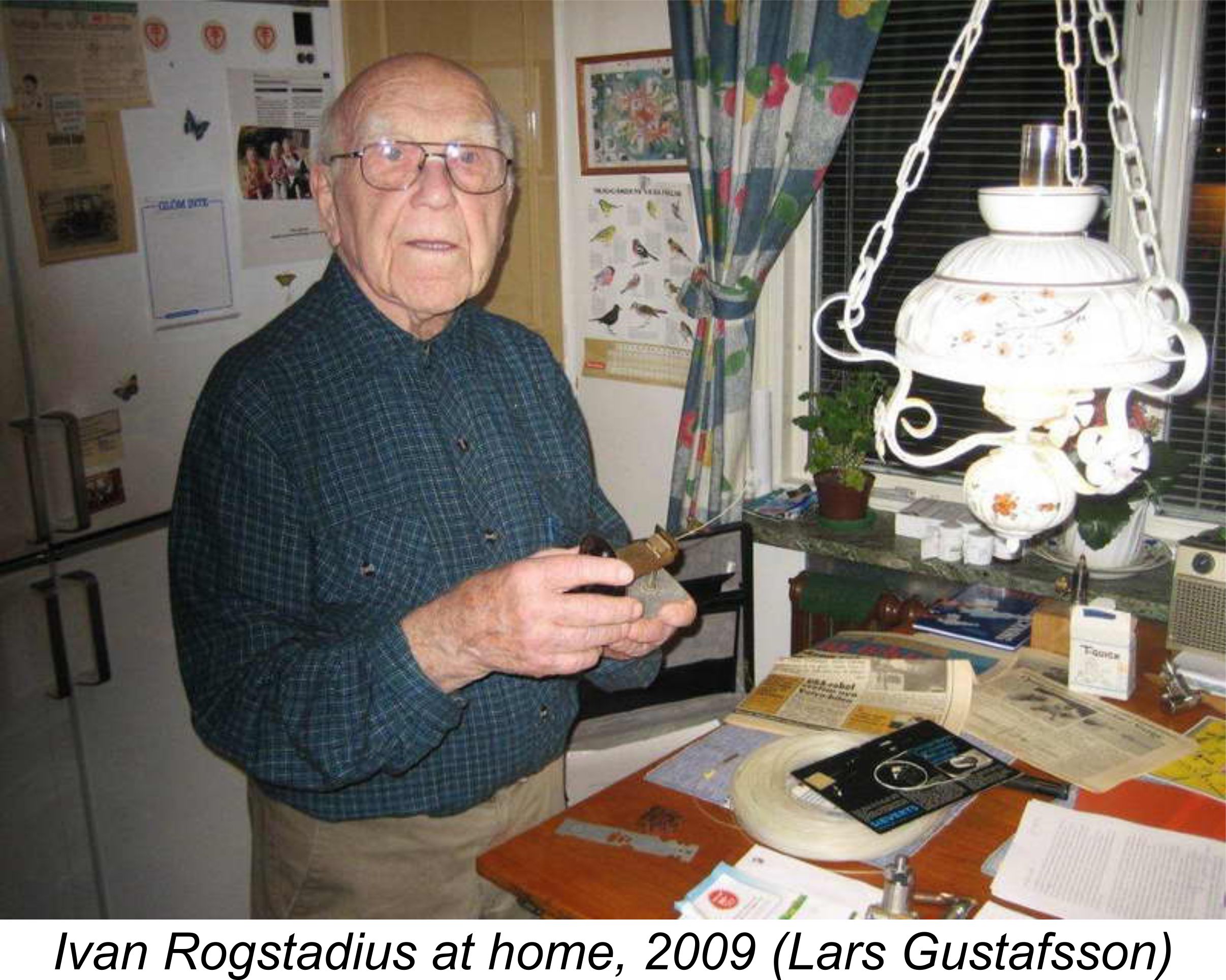 The name Rogstadius refers to Swedish model engineering pioneer Ivan Rogstadius. In the latter part of 1942, at the instigation of the Editor of “Teknik för Alla” magazine, Rogstadius had undertaken the development of a model diesel design specifically intended for home construction. This design was based very closely upon the iconic Swiss Dyno model of 1941. The design was completed during the winter of 1942/43, after which several engines were constructed by Rogstadius. Following successful flight testing in mid 1943, plans and construction details were published in the magazine beginning in December 1943, after which a fair number of examples were constructed by various individuals.
 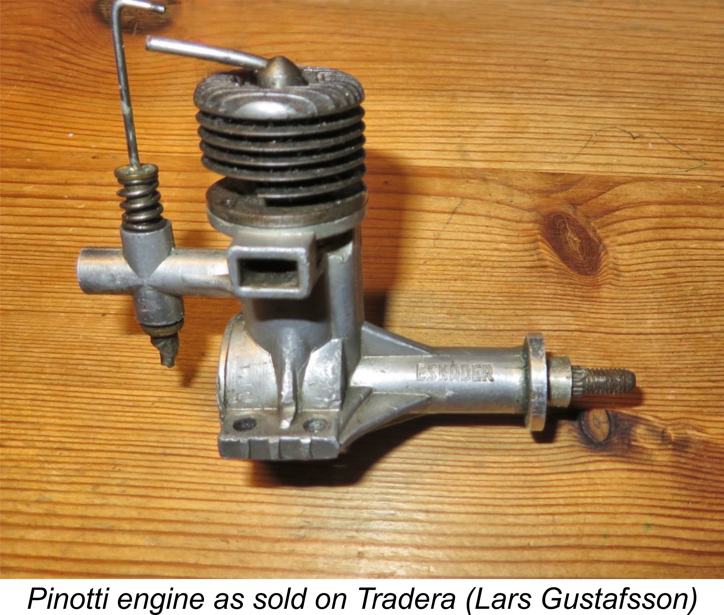 For me, opportunity came knocking in early 2015 when Lars Gustafsson came through once again by drawing my attention to a new listing on Tradera (the Swedish version of eBay). This listing included no fewer than three unidentified engines being sold as one lot. Two of these were obviously Indian-made Aurora replicas of the Mills .75 and 1.3 models, thus being of little interest to me personally. However, I immediately recognized the third engine as an actual example of one of the later Pinotti engines, the GP 1001 model of 1 cc displacement.
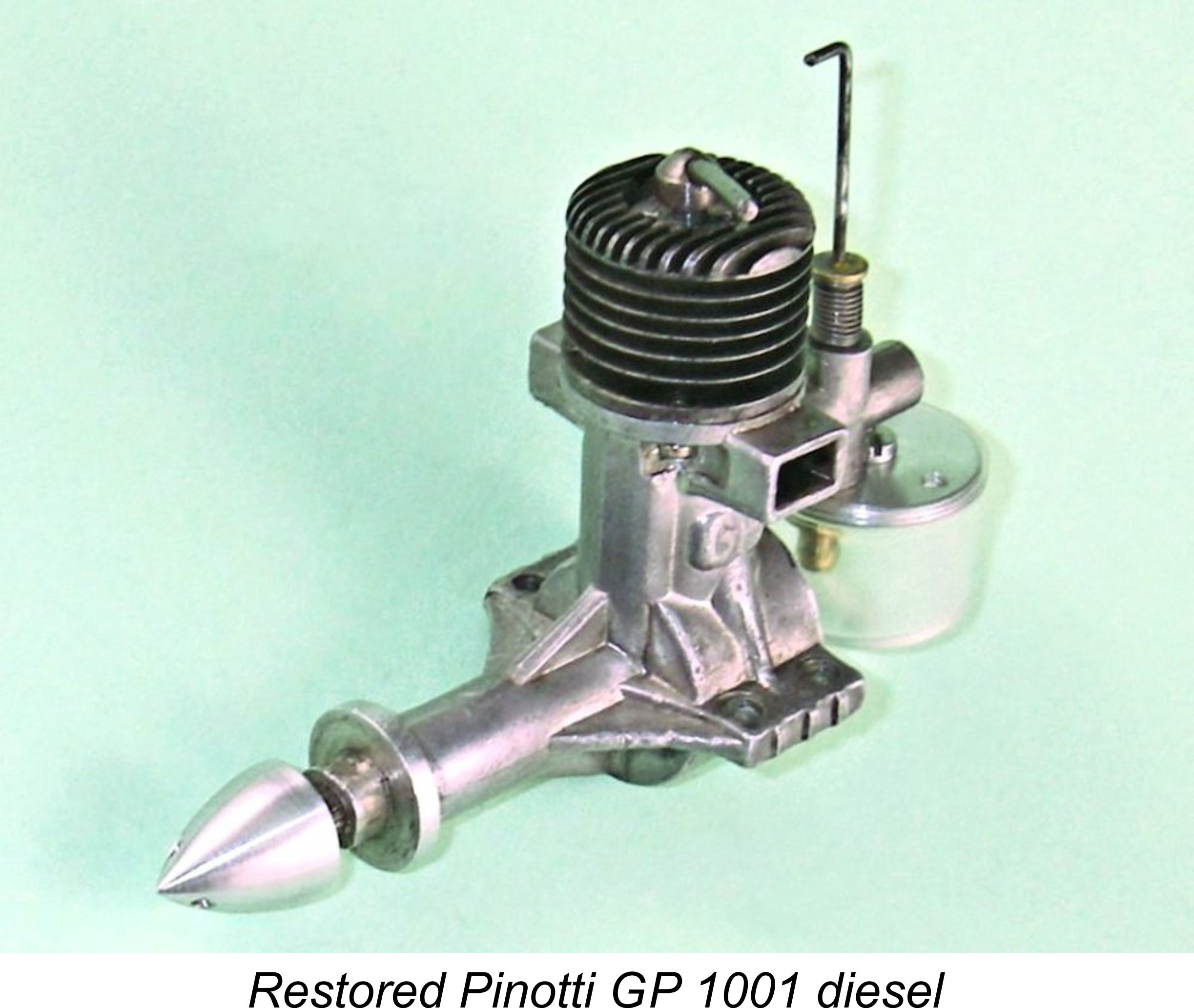 The Pinotti engine proved to be in very good mechanical condition despite having one broken cooling fin (which can easily be seen in the attached images). It was also missing its tank and spinner. Once again, Lars came to the rescue! He established contact with a very talented Swedish modeller, craftsman and model engine restorer, the late and much-missed Kjell Lindqvist (seen below in 2014 with one of his models). Kjell had recently re-created a pair of Pinotti diesels from original crankcases which he had somehow acquired. He had borrowed a complete original engine to use as a pattern, hence having full and accurate details of the missing components for my example. Imagine my delight and gratitude when Kjell agreed to assist in this project by supplying exact replicas of these components at a purely nominal charge!
 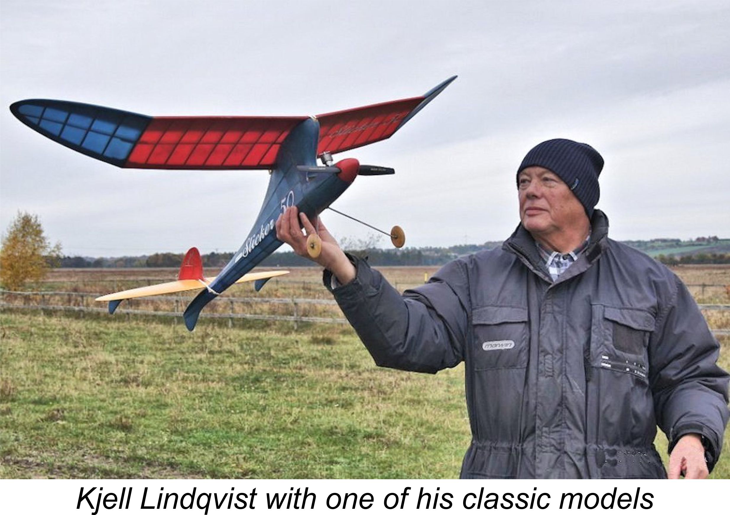 restored to the condition in which it appears in the attached images. Apart from the broken fin plus some of the usual marks of use, it’s now in EXC original condition throughout. It was hard for me to adequately express my appreciation to Kjell for his kindness in this regard. Moreover, his assistance didn’t stop there – he also provided some very useful images along with additional details about Pinotti himself.
 documents relating to the Pinotti story. The Pinotti research project soon became a Gustafsson family affair when Lars’s wife Ulla spent time reviewing Swedish genealogical records, revealing further details regarding the Pinotti family.
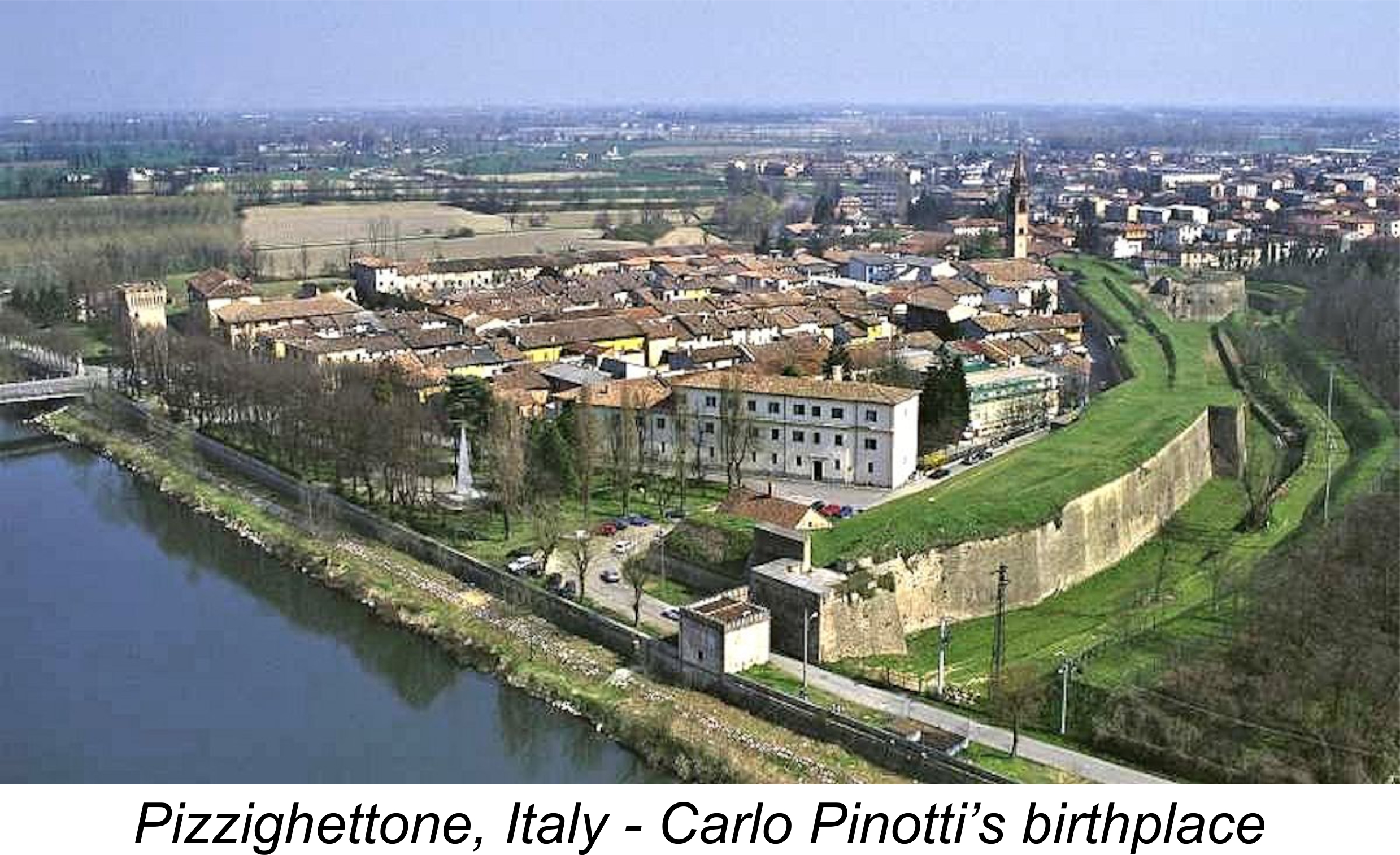 This section of the article will be almost exclusively biographical in nature. Those readers who are interested only in the Pinotti engines rather than in the man himself are encouraged to skip ahead to the following section. I can only comment that if you do so, you'll be missing out on an inspiring tale of perseverance, talent and dedication!
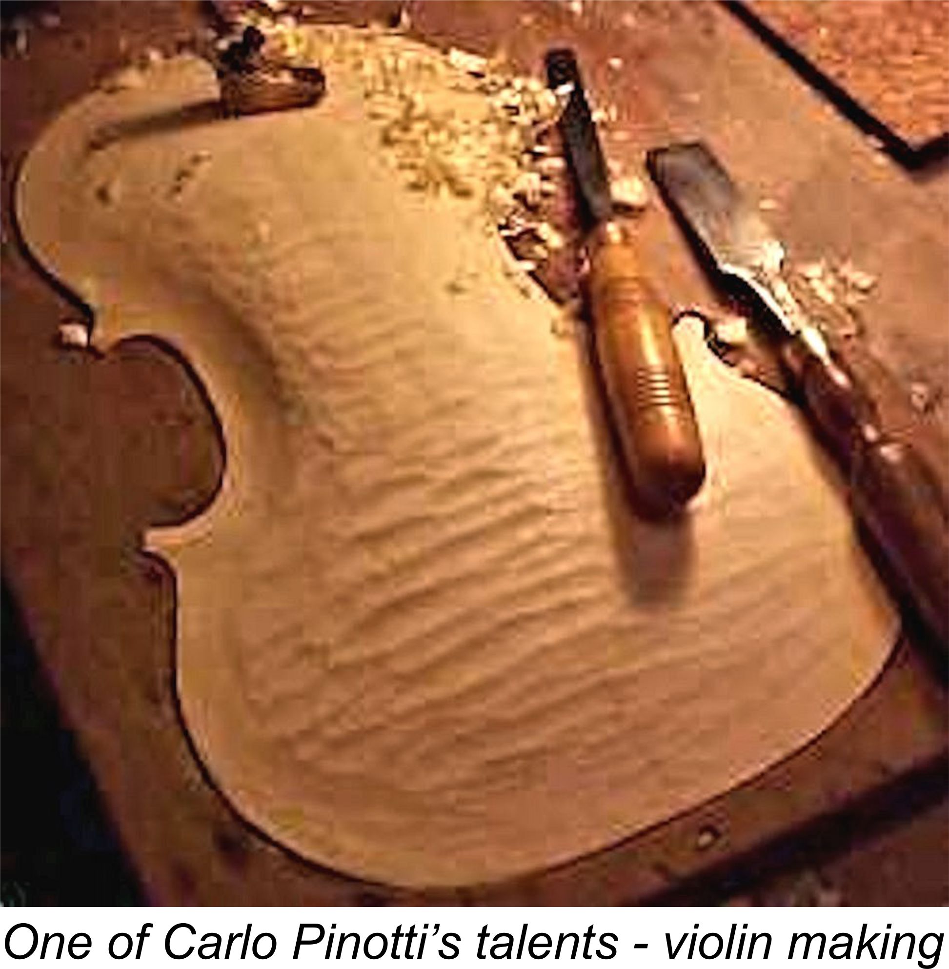 What makes this article very special is that it was based in part upon interviews with Pinotti himself at his home in Malmö, thus putting us in direct contact with our subject. We learn from this article that Pinotti’s talents extended well beyond his musical and engineering professions. He was also a talented musical instrument maker, artist and sculptor, having built several violins which were on display in his home, as were a number of fine oil paintings and sculptures which he had created himself. In addition, he had designed and built a projector for which he had obtained a Swedish patent. As if this wasn’t enough, he was also a talented cook, specializing in Italian fish dishes. A real throw-back to the Italian Renaissance!
 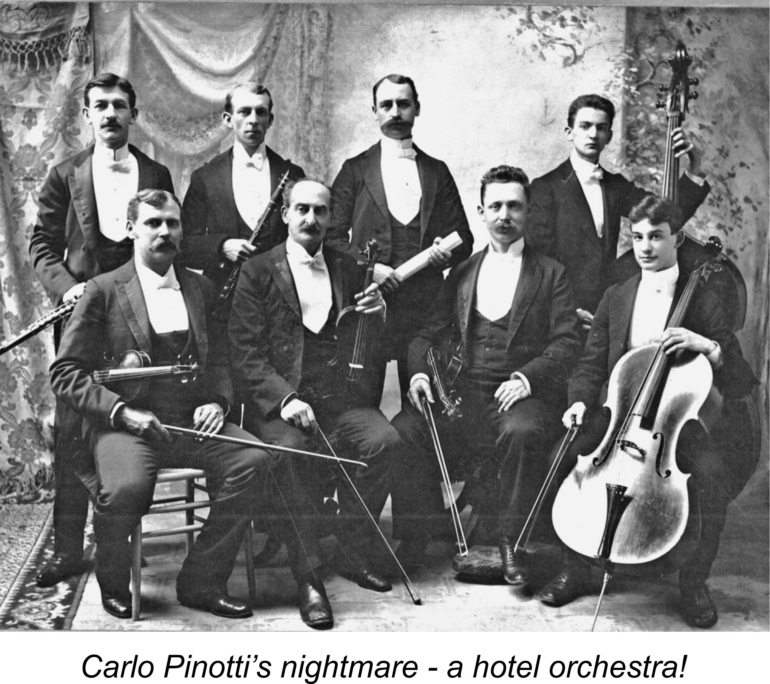 The previously-referenced article from issue 2 of ”Oldtimer” for 2011 provides some important evidence regarding Carlo Pinotti’s motivation for becoming involved with model engine manufacture. It seems that at the time when the original late 1930’s article was written, Pinotti was earning his living by playing in the evenings in the orchestra of the first class Hotel Savoy in Malmö. This was the job as a “restaurant musician” to which reference was made earlier. By his own account, Pinotti did not like this at all, considering himself to be trapped in a situation where he had to play “popular” music rather than the “high class” (classical) music which was his first love.
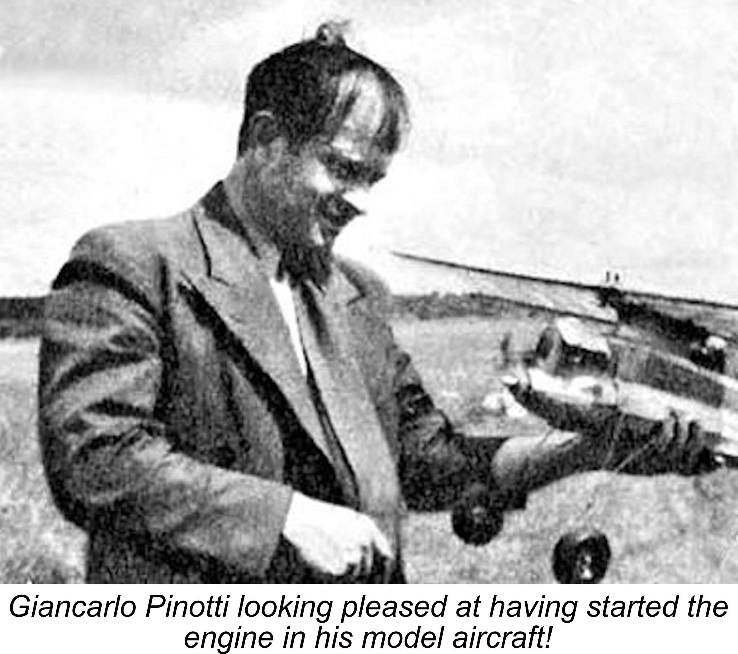
 As matters turned out, the planned export of engines to Italy never gained any momentum, most likely because Pinotti was unable to manufacture the engines in the kind of quantities typically expected by importers. This led him to the logical conclusion that the best alternative approach would be to find a local dealer who would sell the engines over the counter to Malmö-area modellers in whatever numbers Pinotti was able to manufacture.
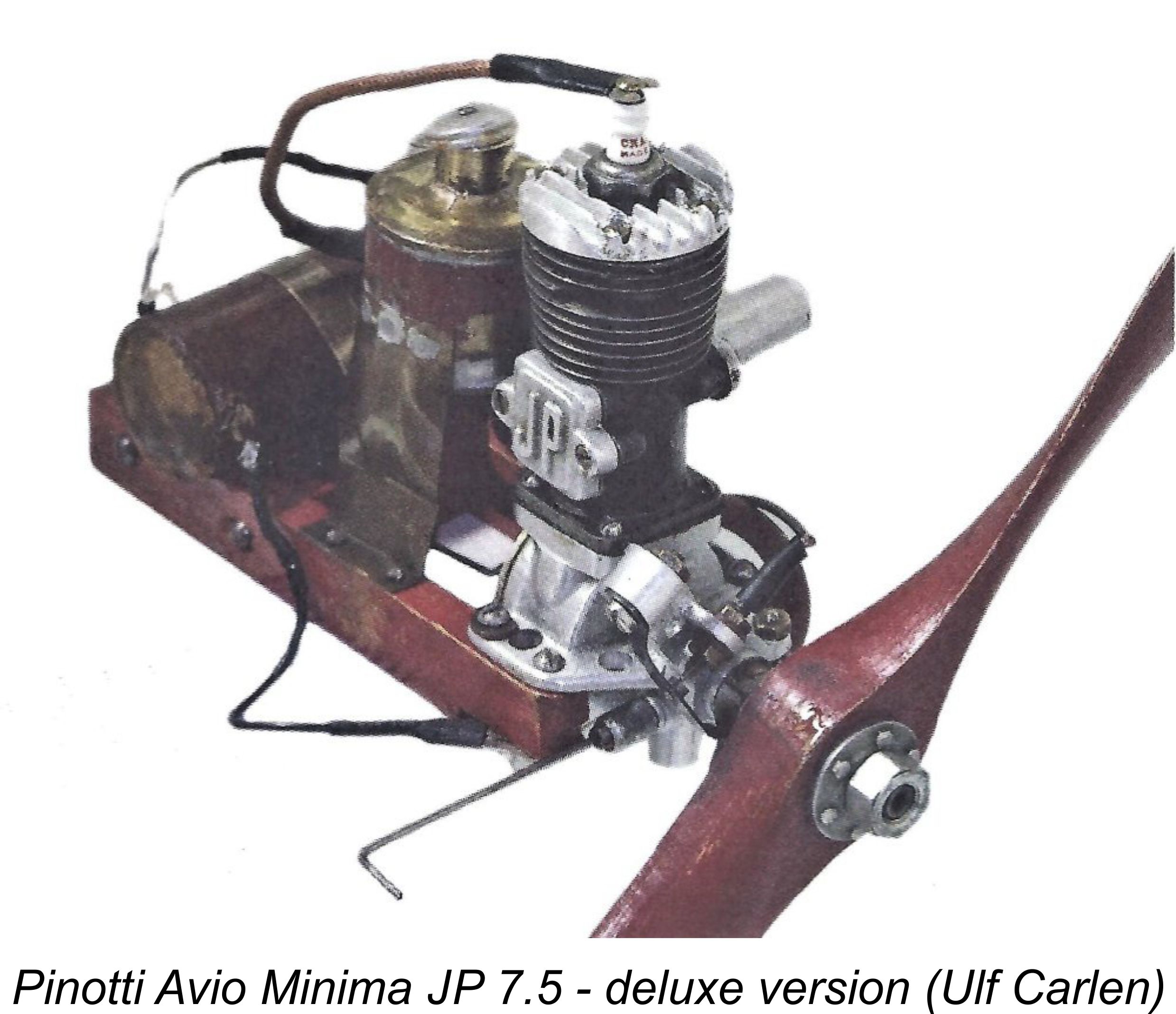 Pinotti was clearly far more concerned with ensuring that his products were well designed and produced to a consistently high standard of precision than he was with "prettying" them up externally. Consequently the GP and JP 7.5 units are undeniably a little rough on the outside in some respects. This focus on precision is entirely laudable - when resources are limited (as in this case), far better to put the bulk of one's effort into the achievement of results which will contribute to improved performance and longevity than with cosmetic enhancements which contribute nothing to those goals.
 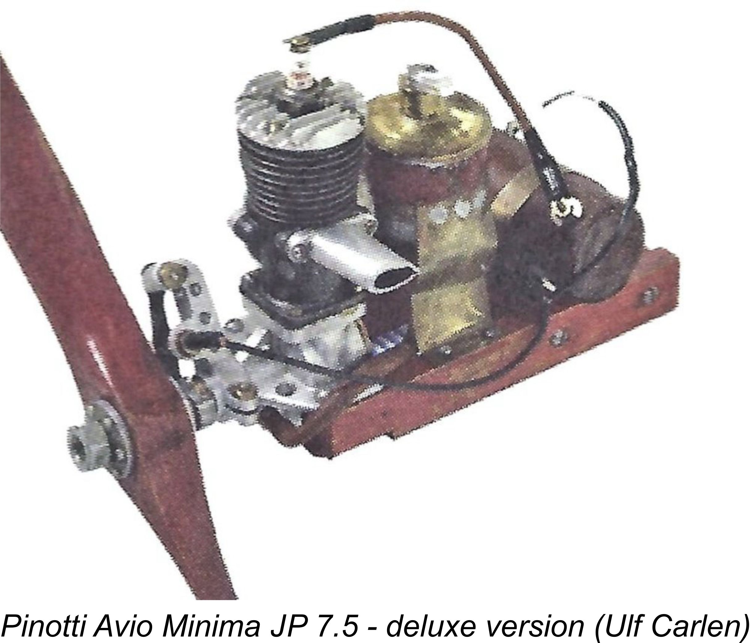 That first Pinotti engine was a spark ignition model having bore and stroke measurements of 21.0 and 21.9 mm respectively for an actual displacement of 7.59 cc (0.463 cuin.). Despite its true displacement, the engine was always referred to as the GP (or JP) 7.5 - close enough! It featured crankshaft front rotary valve (FRV) induction with an updraft intake.
 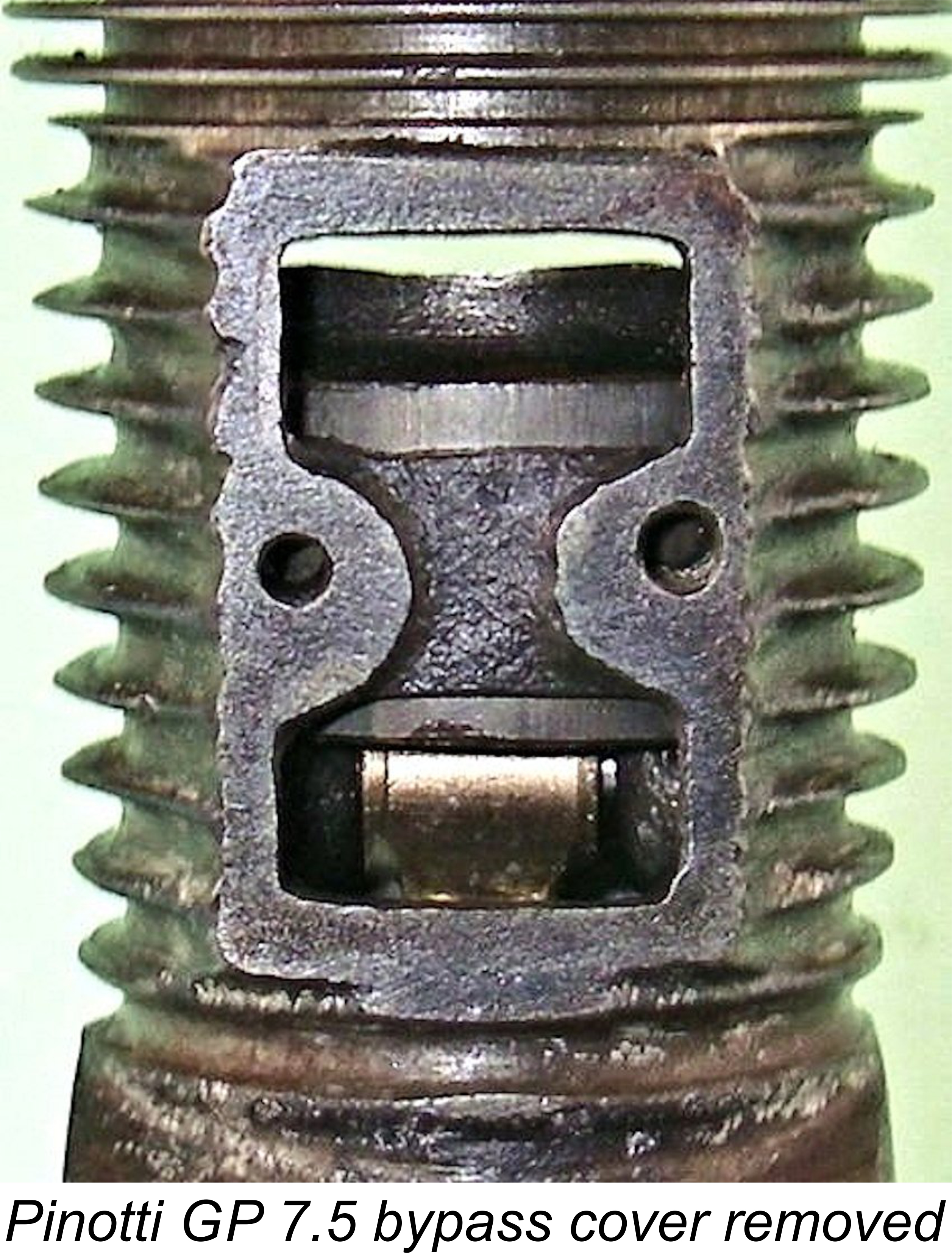 naturally resulted in the fins being rather brittle - the illustrated example has a broken fin, which can be clearly seen in the accompanying illustrations. Handle with care.......
 the JP 7.5 cc models manufactured by Pinotti. Although a little rough in terms of its external finish, this completely original example is internally fitted to a very high standard indeed - compression seal is superb, while all bearings are completely free from play despite the running which the engine has clearly done in the past. The cast and machined bronze I-sectioned con-rod in particular is a work of art!
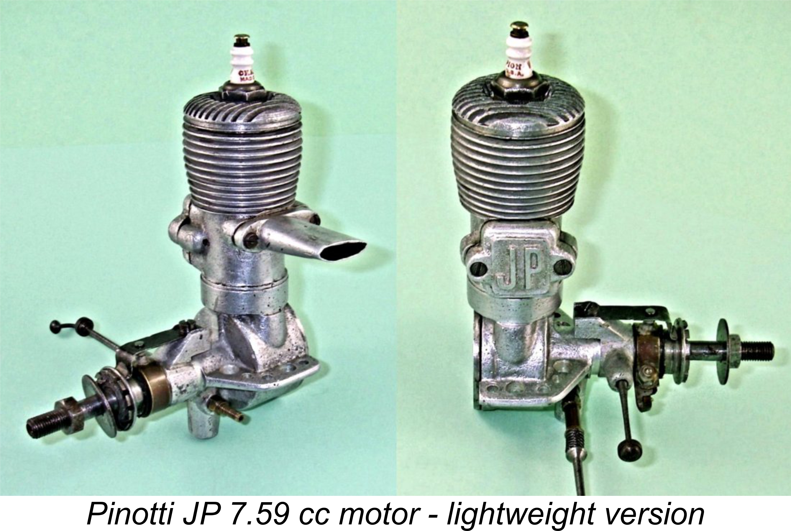
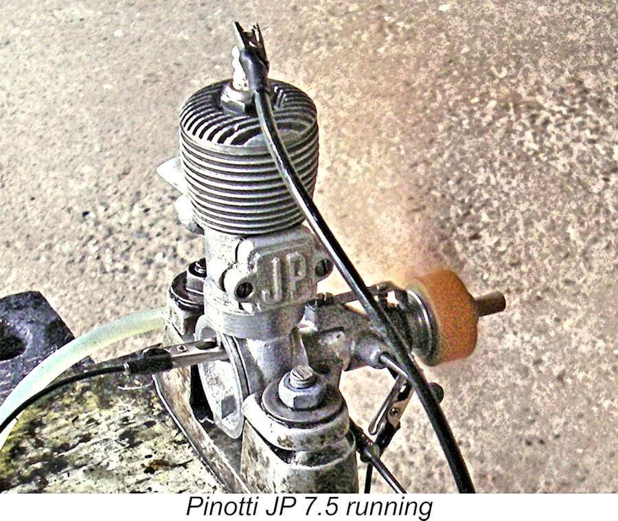 would have presented far more of an assembly challenge than a bolt-on design. However, the use of this technology in the context of an individually-produced model of this sort renders this limitation relatively insignificant.
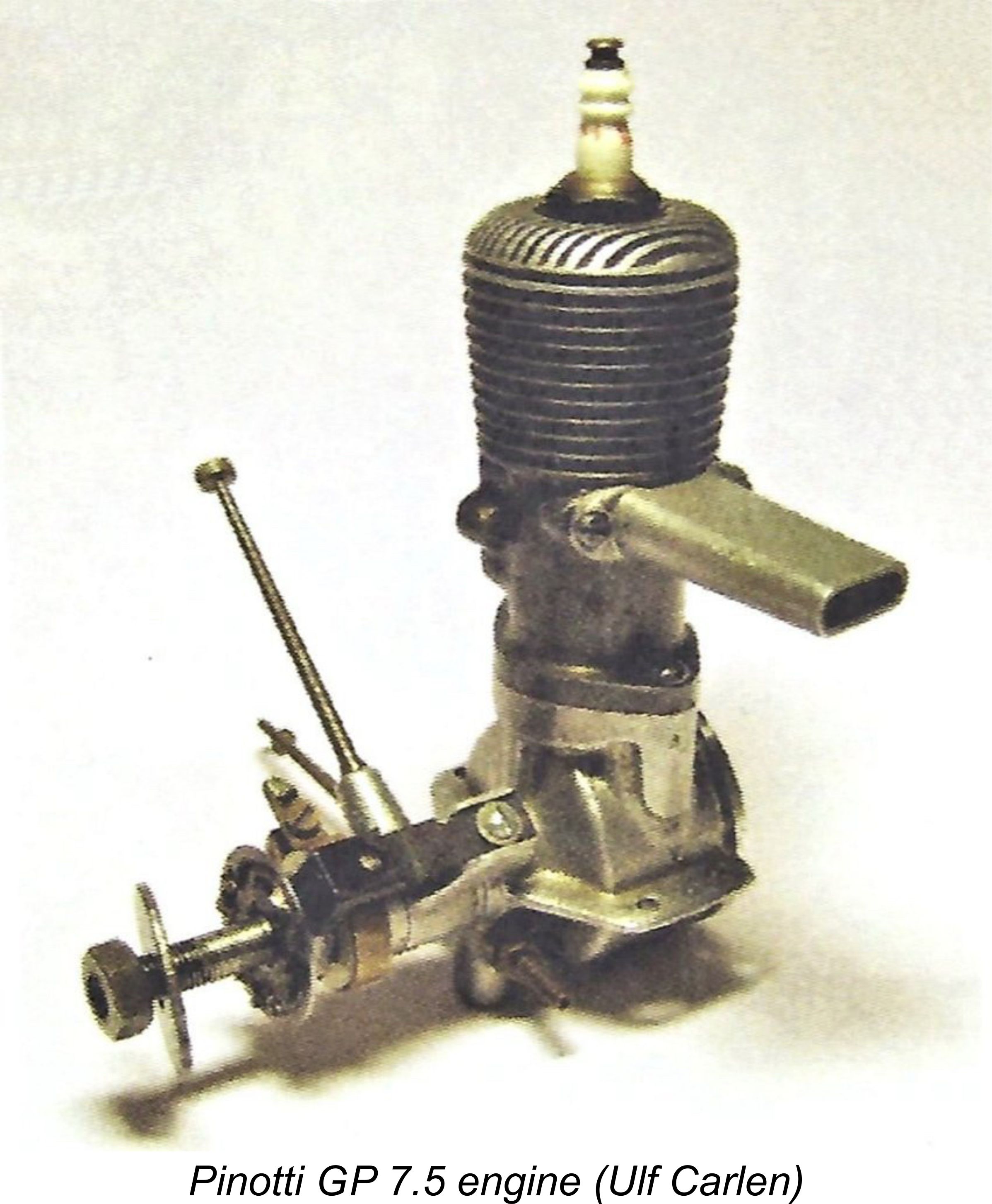
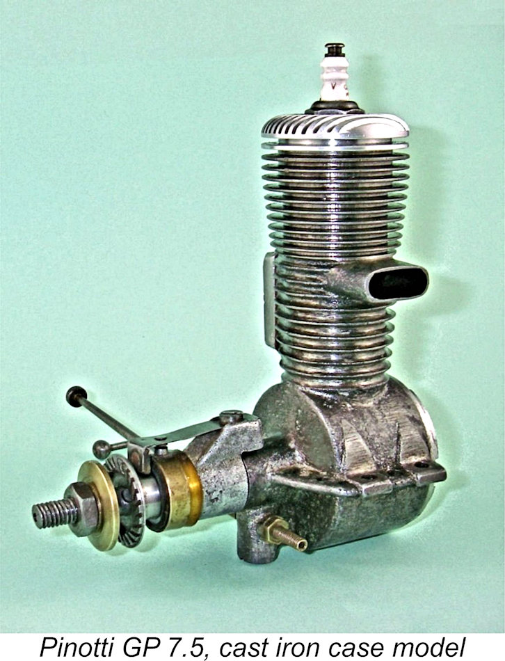
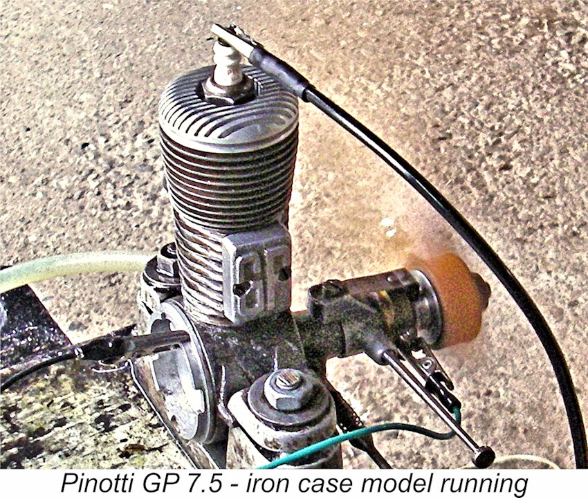 Just for fun, I gave this one a few test runs at the same session which saw the companion JP 7.5 being put through its paces, as reported earlier. I used the same Top Flite 12x6 wood prop and the same fuel mix. The GP 7.5 proved to be every bit as sweet-handling and fine-running an engine as its far lighter sibling, starting instantly and running perfectly with excellent response to the controls.
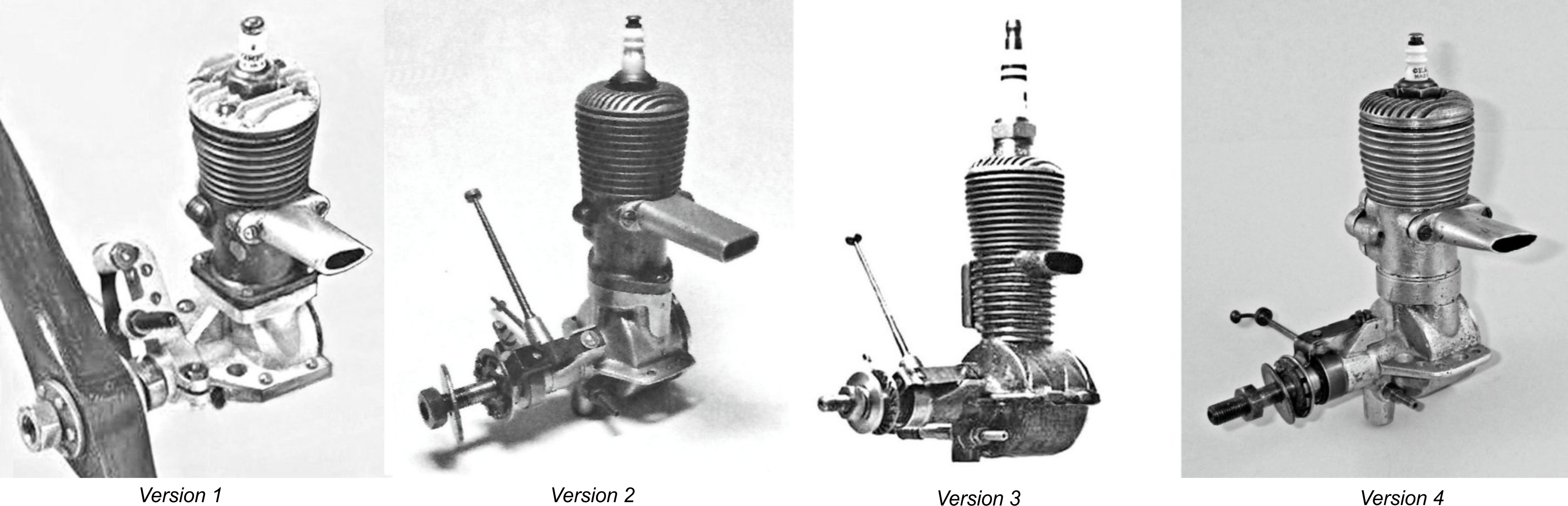
 Truedsson made a further significant contribution to the Pinotti cause in 1940 when he designed and later kitted a large American-style model expressly for Pinotti's GP 7.5 engine. Naturally this design was given the name ”GP-Special”. This kit was a great success, remaining on sale for many years. Indeed, the design remains in use today - equipped with a modern 4-stroke engine, the GP-Special makes a beautiful old-timer R/C model.
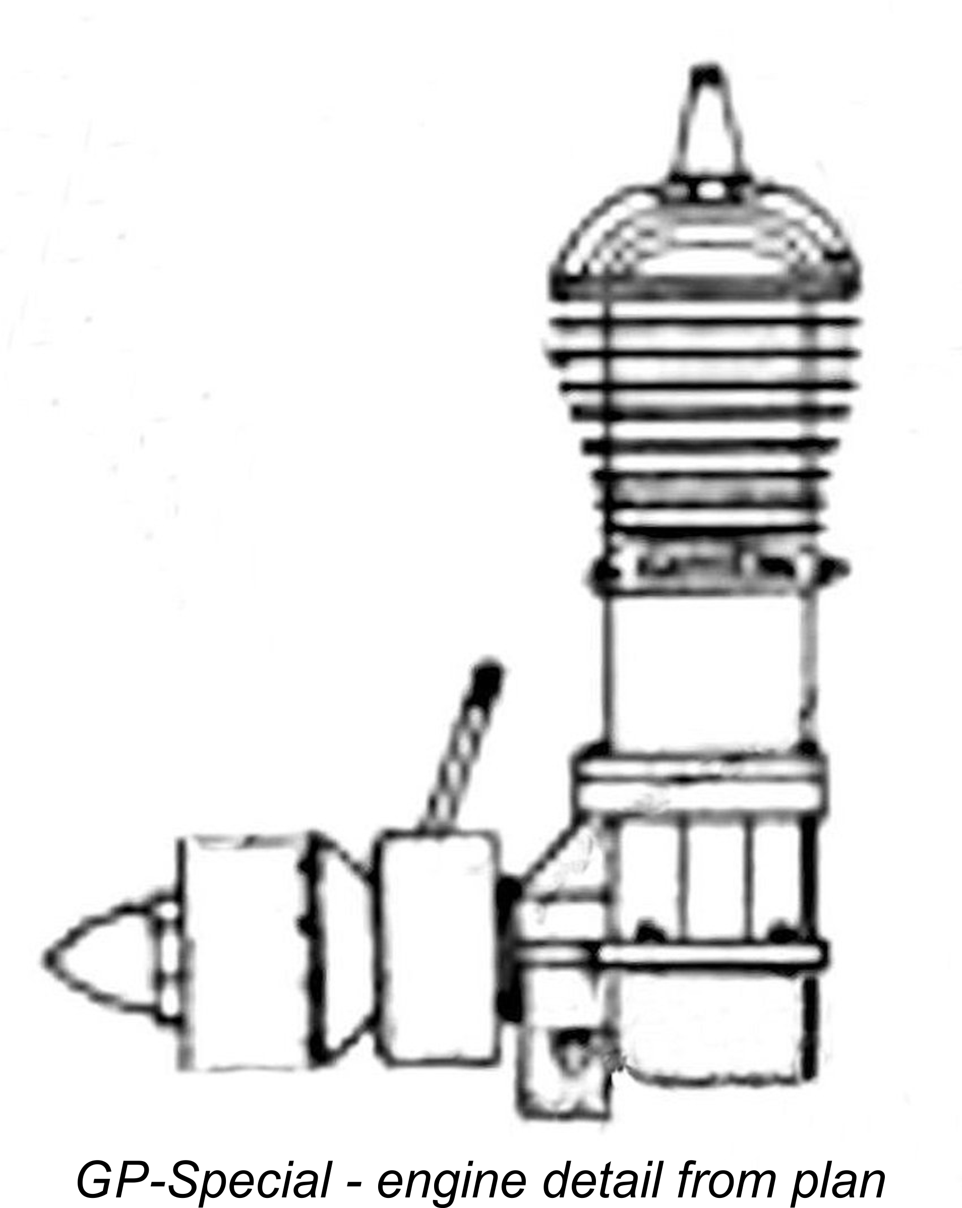 those already! Although of basically similar design to all of the other variants described earlier, it has a more bulbous cylinder fin configuration, also having what appears to be an Ohlsson-style enclosed timer of more advanced design than the open-frame unit employed on all other presently-known variants. The use of this type of timer had evidently permitted the re-introduction of a strengthening web at the top of the main bearing where it meets the crankcase. This was a feature of the original "deluxe" model with its transverse timer (see above images). Finally, the illustrated engine sports a neat spinner nut similar to those used later by Pinotti on his diesel models, of which more below.
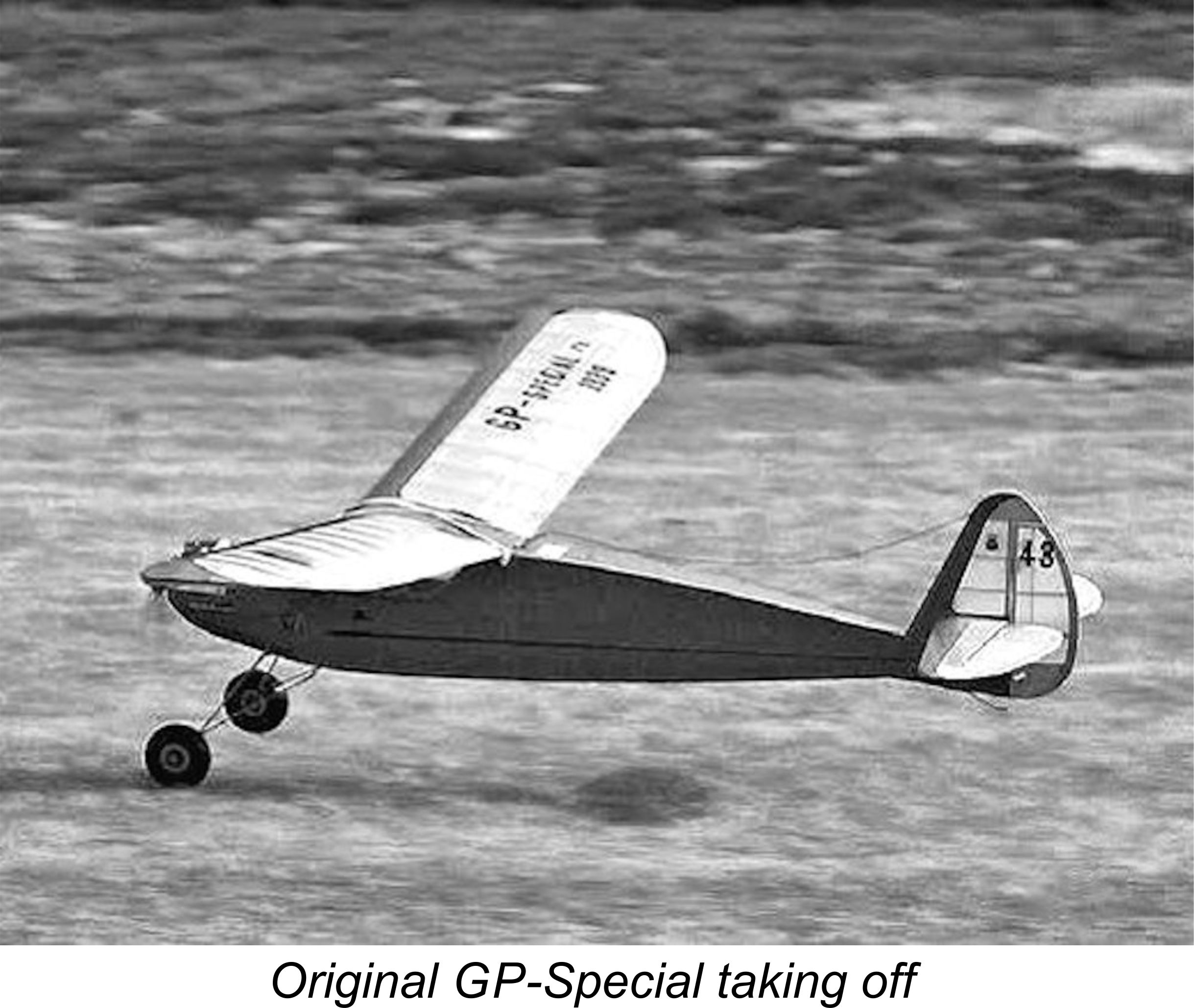 towards the city. While chasing it by car, they saw the plane begin to circle above the large Malmö football stadium, eventually losing height and finally making a neat landing on the playing field in the middle of an ongoing game. This of course prompted the referee to blow the game off! Apparently, the spectators were none too amused ……….......
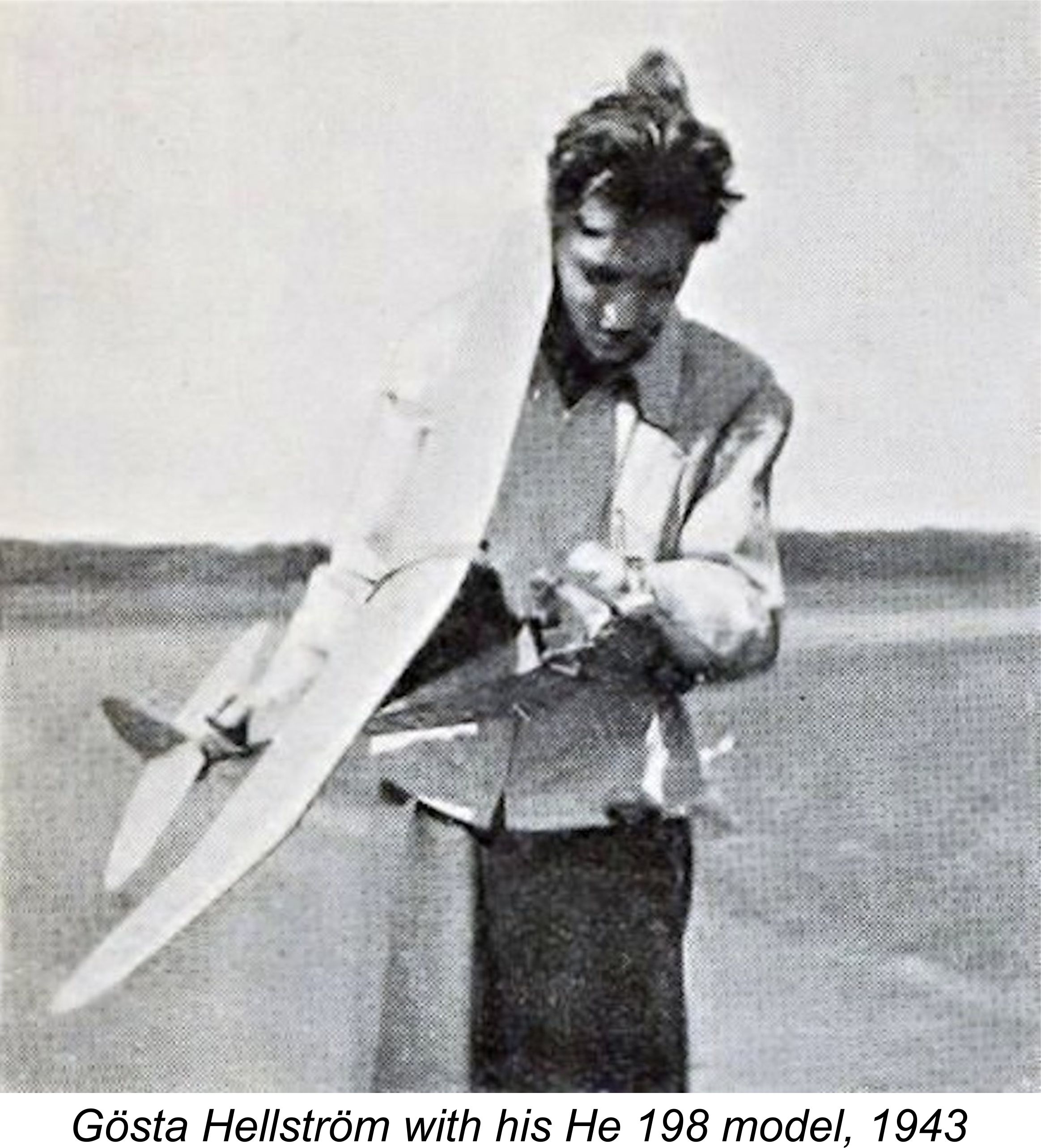 Ekström and Allan Dahl, both of whom were profiled in issue 1 of ”Oldtimer” for 1993. Cleary the engine had acquired a very good reputation among serious modellers.
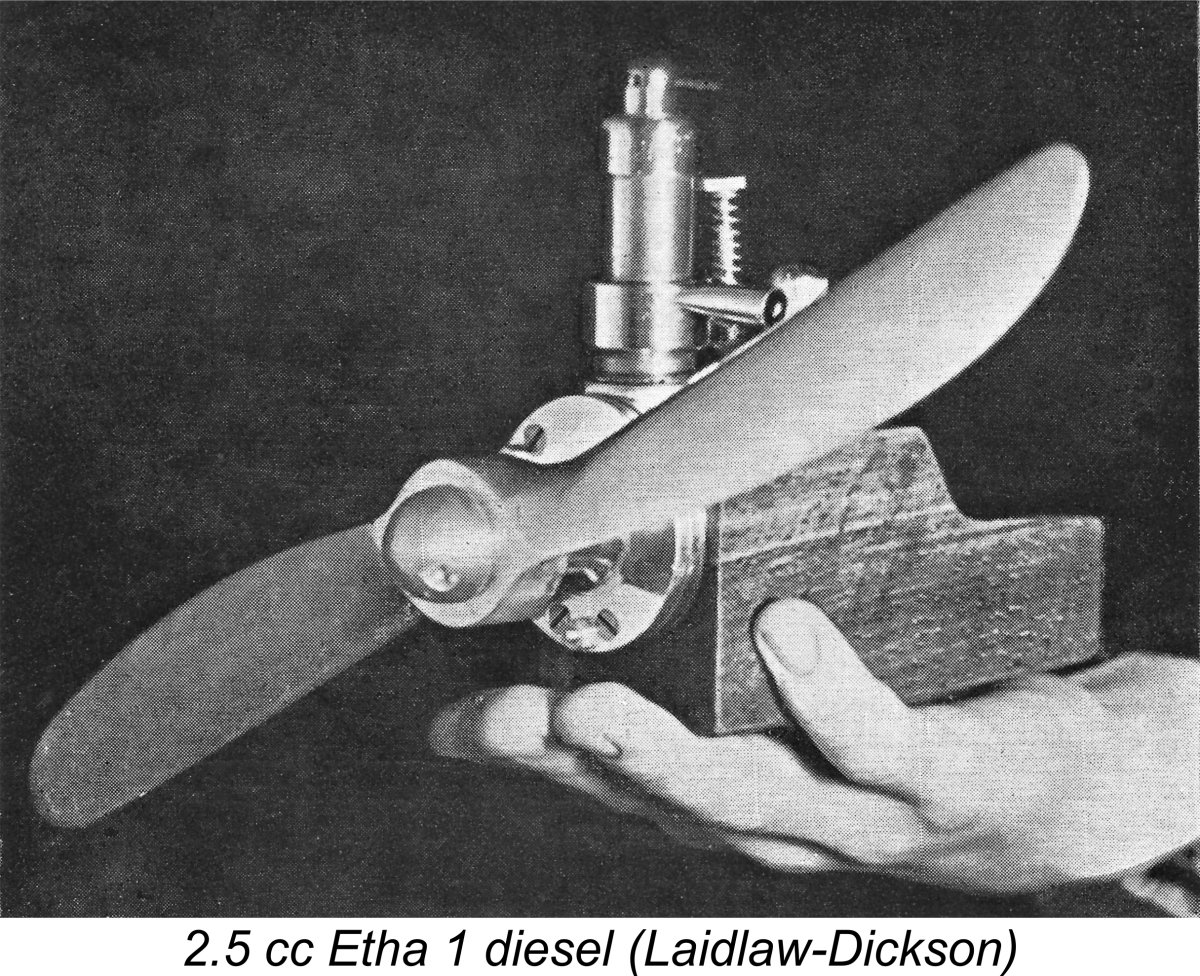 Returning now to Switzerland to pick up our main thread once more, some ten years after receiving his 1928 patent Ernst Thalheim went into production with a series of model diesel engines which were marketed from 1938 onwards under the Etha label, derived of course from Thalheim’s name rather than from a primary ingredient of the engines’ fuel! These appear to have been the world’s first commercially-produced model "diesel" engines. It’s a bit of a mystery why it took Thalheim ten years to actually begin to capitalize upon his patent …..
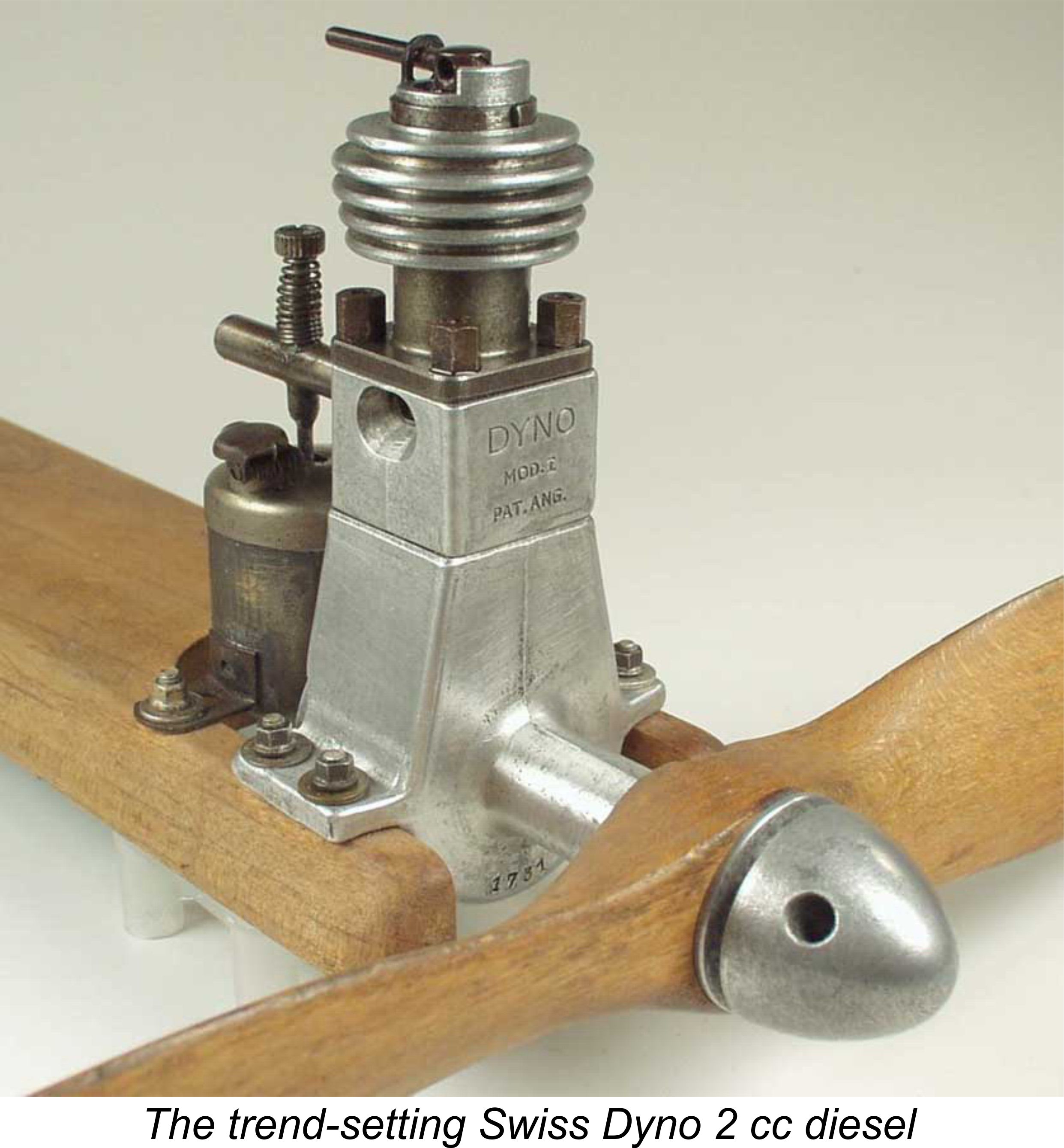 News of the new technology reached neutral Sweden in 1942, along with an actual example of the Dyno engine which somehow crossed war-torn Europe to come into the possession of Gunnar Fahlnäs, then the Editor of the popular Swedish technical magazine “Teknik för Alla”. Impressed with the performance of the Dyno, Fahlnäs commissioned Swedish model engineering pioneer Ivan Rogstadius to develop a Dyno-based design for home construction, using his original Dyno as the prototype.
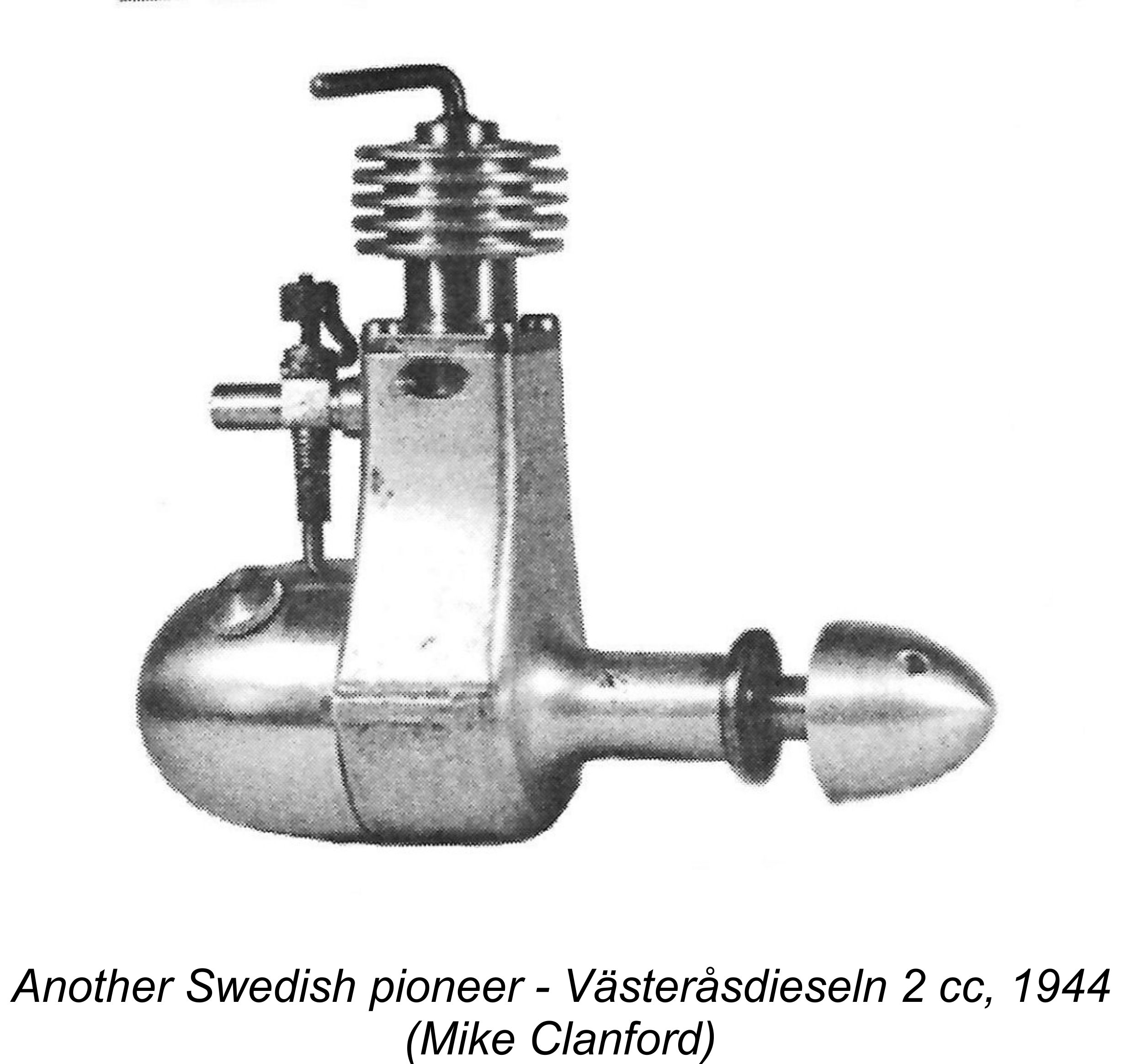 along those lines. He had re-established his machine shop in a shed in the back yard of his new residence at Åsögatan 81 in South Stockholm, hence being well-equipped to undertake this experimental work while still producing the odd example of his well-established GP 7.5 spark ignition model during this period. The early date of his diesel experiments is confirmed by their being mentioned in “Flygtidningen” (Flight Magazine) in the autumn of 1942, at which time Ivan Rogstadius was still developing the preliminary design of his Dyno-based engine.
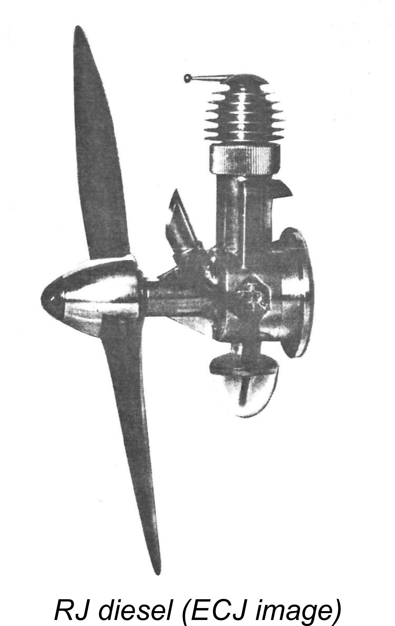 commercial production in Sweden, leading the competing Västeråsdieseln 2 cc model produced by the Västerås-based Johansson brothers by some months.
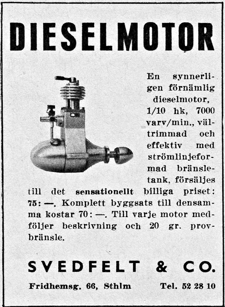 The Rogstadius design was never put into series production, at least with the involvement of Ivan Rogstadius himself, having been intended all along as a project for home construction. Ivan was not a model aircraft enthusiast per se, consequently moving on to other model engineering ventures following the successful completion of his assignment from “Teknik för Alla”.
 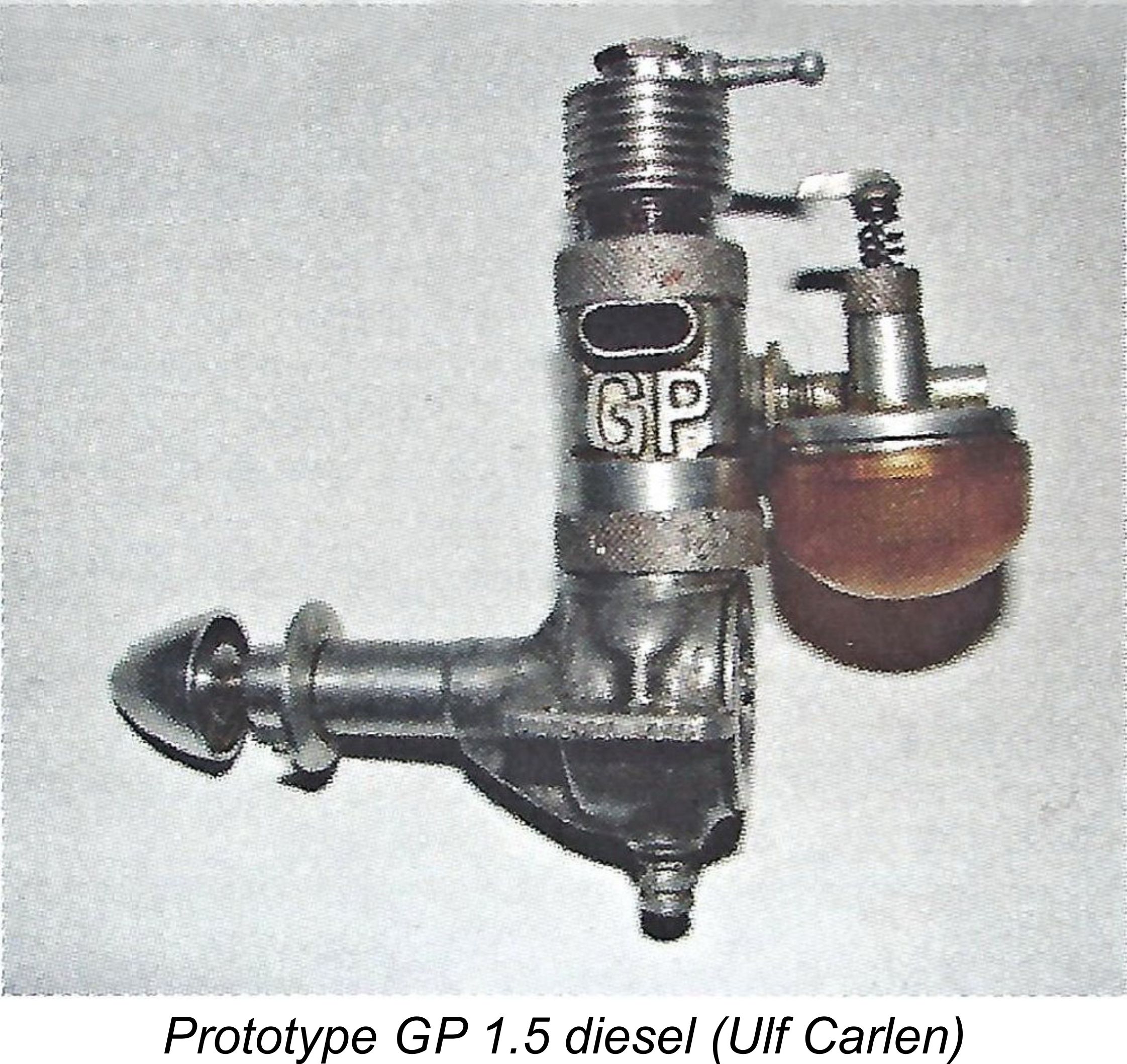 I personally believe this to be a red herring - to me, it seems most likely that Laidlaw-Dickson was in receipt of hand-written information in which the true initials GP were rendered with a poorly-executed letter G. The other possibility is that someone told him that the engines were designated by the maker’s initials and then gave the maker’s name as Carlo (not Giancarlo) Pinotti! We’ll never know, nor does it matter much.
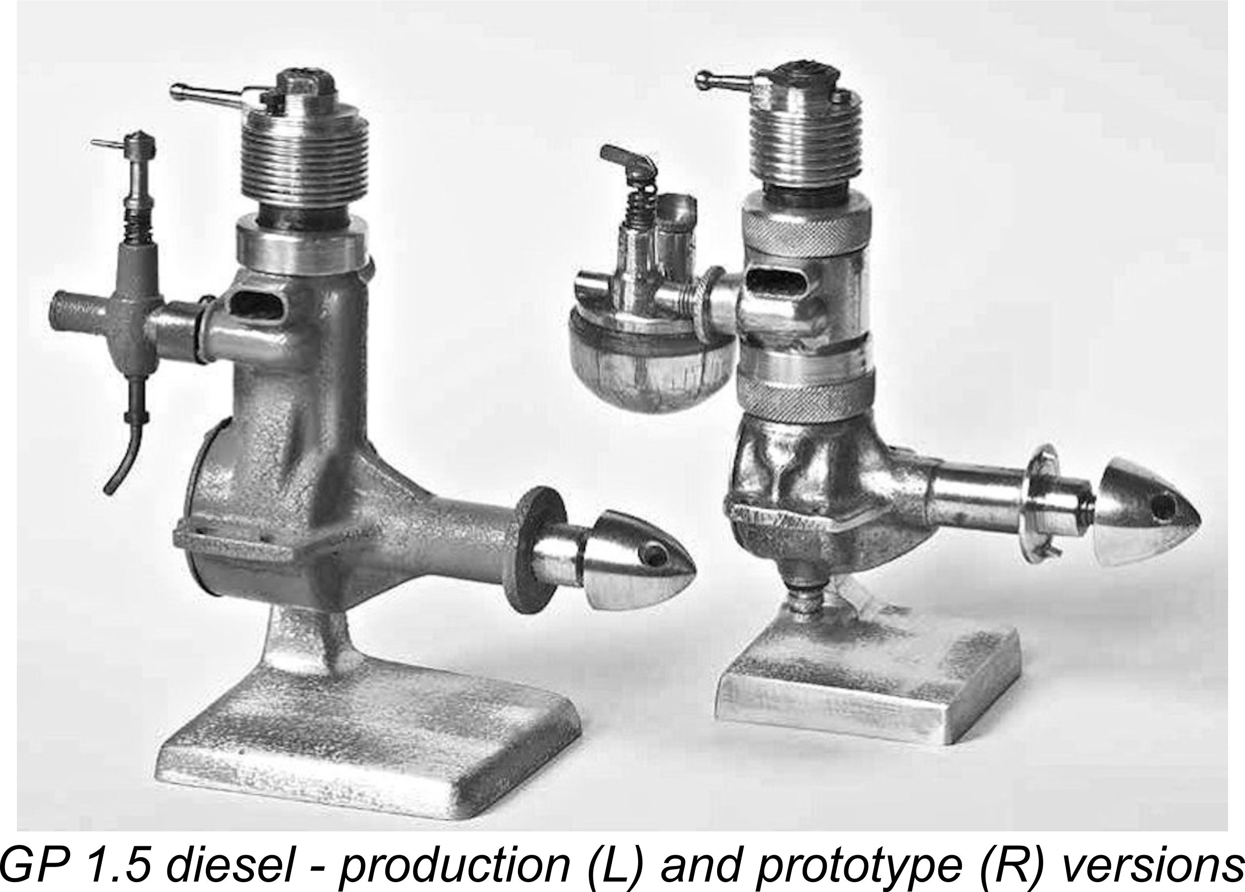 effect that the bore and stroke of this model were 11.0 mm and 16.0 mm respectively for a displacement of 1.52 cc (0.093 cuin.). These figures check out on an actual example of the engine. Ulf also stated that the GP 1.5 weighed 110 gm (3.88 ounces), which is somewhat at variance with the weight of 135 gm (4.76 ounces) reported by Laidlaw-Dickson. It is also at odds with the actual checked weight of a present-day survivor (see below), which weighs in at 125 gm (4.41 ounces). You decide ..........
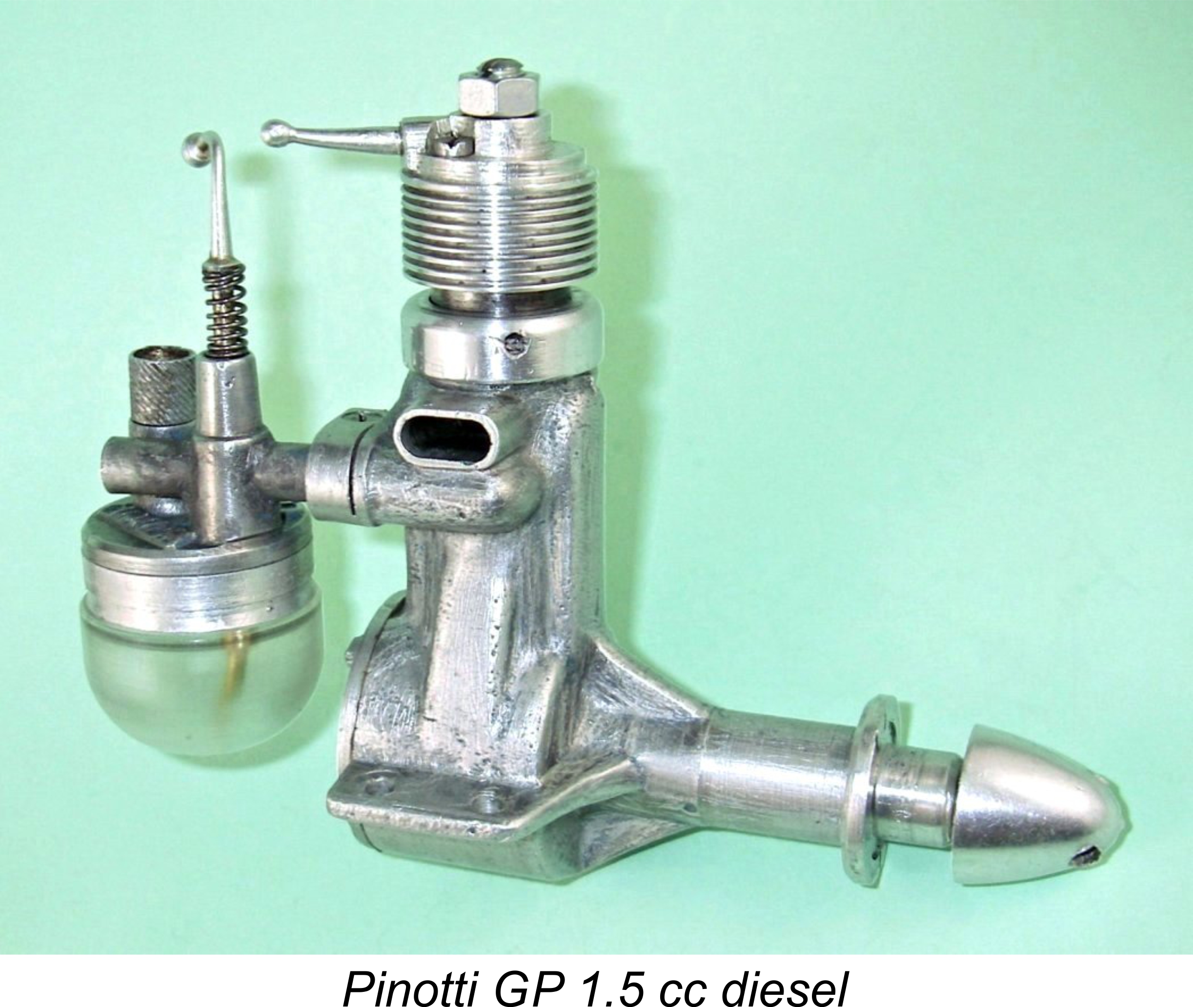 The engine was once again missing its tank along with its compression screw and spinner nut, leading us to approach our valued colleague Kjell Lindqvist yet again. Following consultation with Sten Persson to obtain accurate details of the originals in Sten's collection, Kjell was kind enough to make another of his superb replica tanks. He also made and fitted the appropriate spinner nut and compression screw to complete the engine. This put the GP 1.5 back into complete and original condition, all ready for testing. It's hard for me to adequately express my appreciation for Kjell's kindness and skill.
  Having done this, I attempted to remove the top layer of paint while leaving the original painted surface unaffected. This proved to be an impossible task - anything that removed the top coat also removed the underlying layer. Eventually, I decided simply to remove all of the paint. As one of the images reproduced below proves, some of these production models did have plain natural-finish crankcases - this is now one of them. Speaking personally, I've never been a fan of painted crankcases - the paint invariably chips or wears, quickly imparting a rather tatty appearance to the engine.
 It turned out that my acquisition of this engine was extremely fortuitous, since a close examination revealed a significant number of unique features which would otherwise have escaped my notice. For a start, the engine provides irrefutable evidence to the effect that
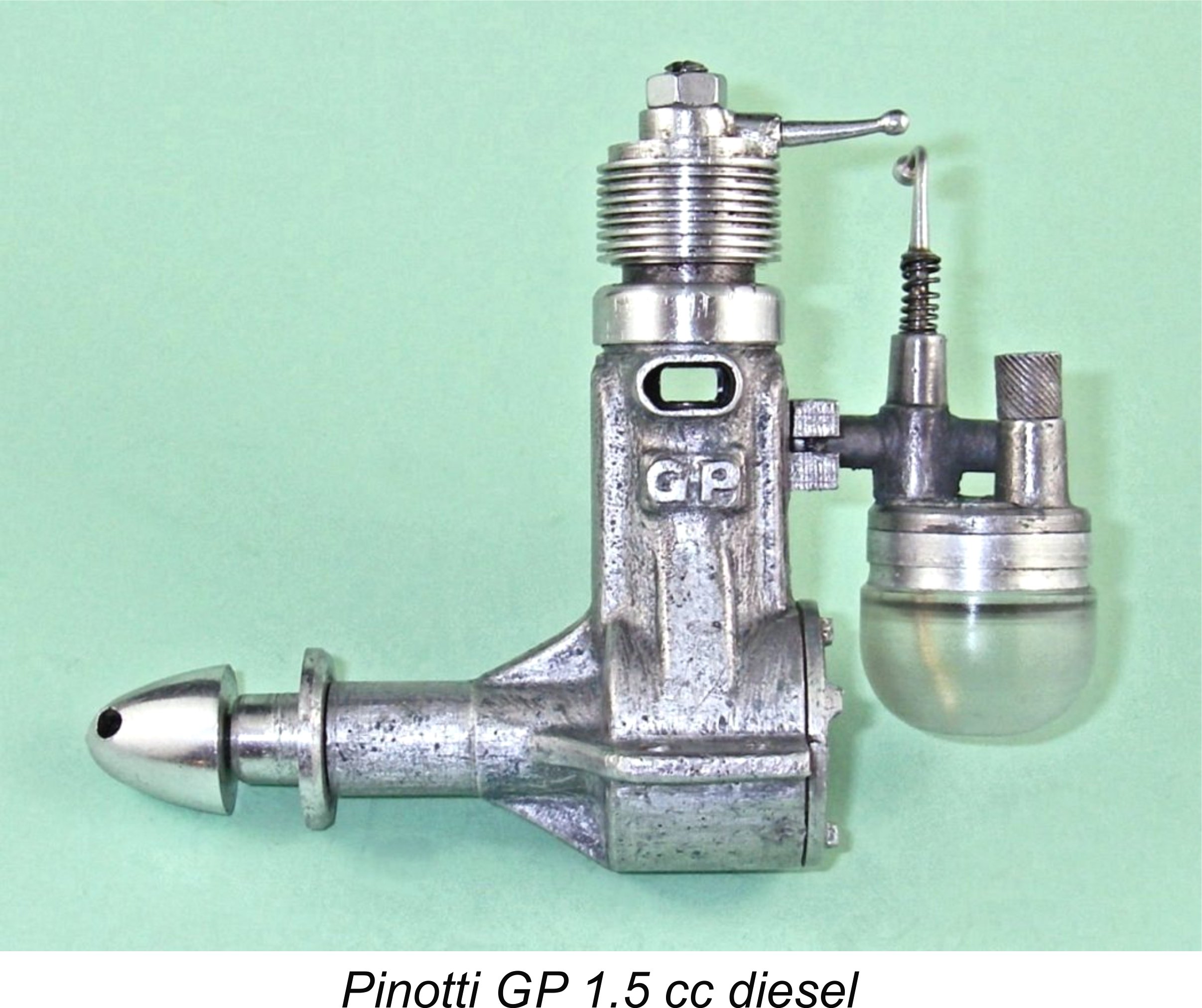 Even the way in which the tank bowl is mounted is distinctive. The lower circumference of the cast tank top is externally threaded to accomodate an internally threaded turned alloy ring. The externally-threaded tank screws into the protruding lower portion of this ring. One wonders why Pinotti didn't simply use an internally threaded tank which could be screwed directly onto the tank top. My best guess is that by approaching things as he did he made it possible to increase fuel tank size by using alloy rings of different depths. This man seems to have thought of everything!
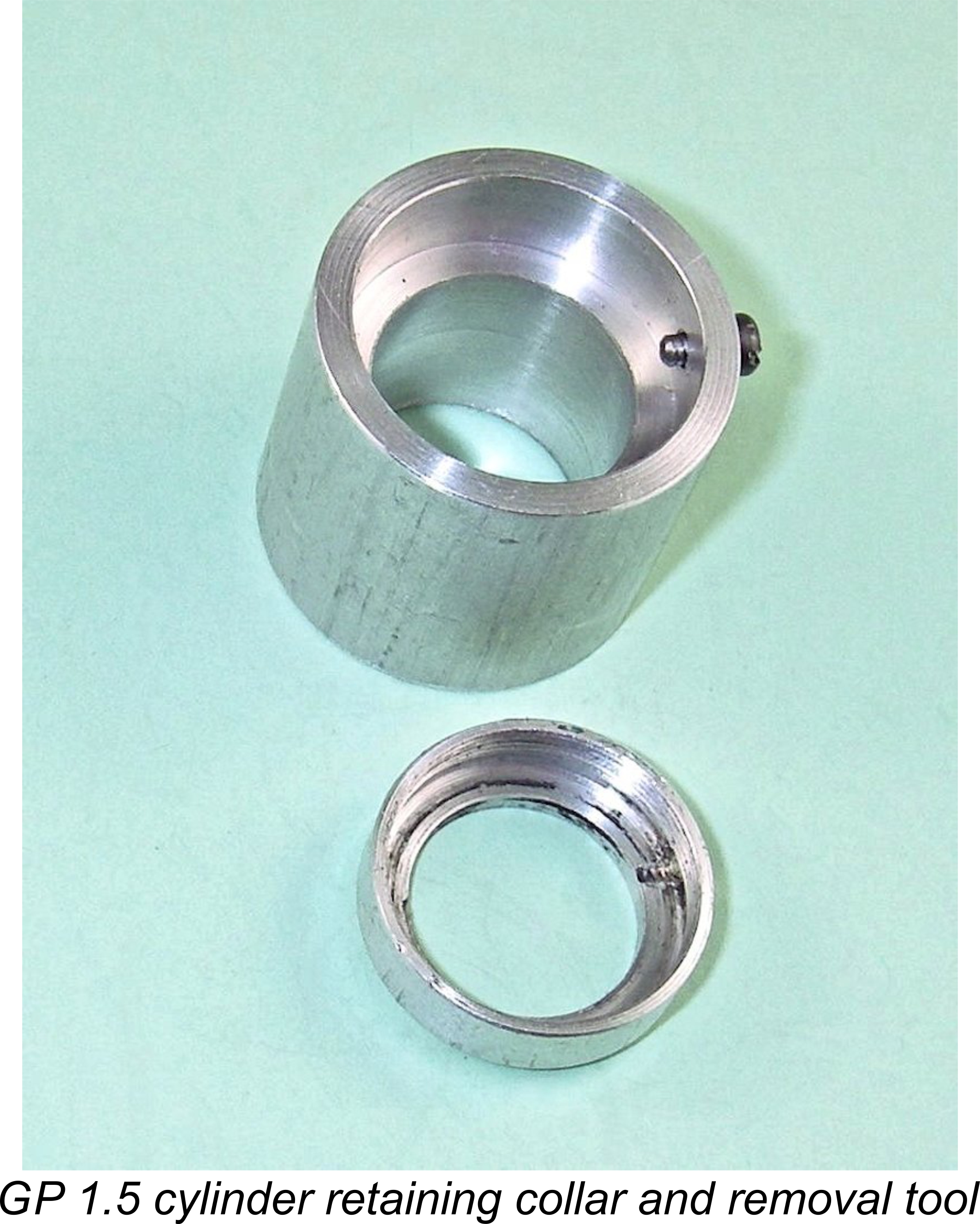 So far so good, but in order to fully appreciate the nuances of the design it was necessary to remove the cylinder. My primary motivation for dismantling the engine to this extent was my observation through the exhaust ports that the cylinder appeared to be partially rotated in an anti-clockwise direction (viewed from above). To be precise, the exhaust ports appeared to be offset to the right when viewed through the exhaust stacks. I wanted to determine whether this was an assembly error on the part of a previous owner or whether it was an original design feature.
 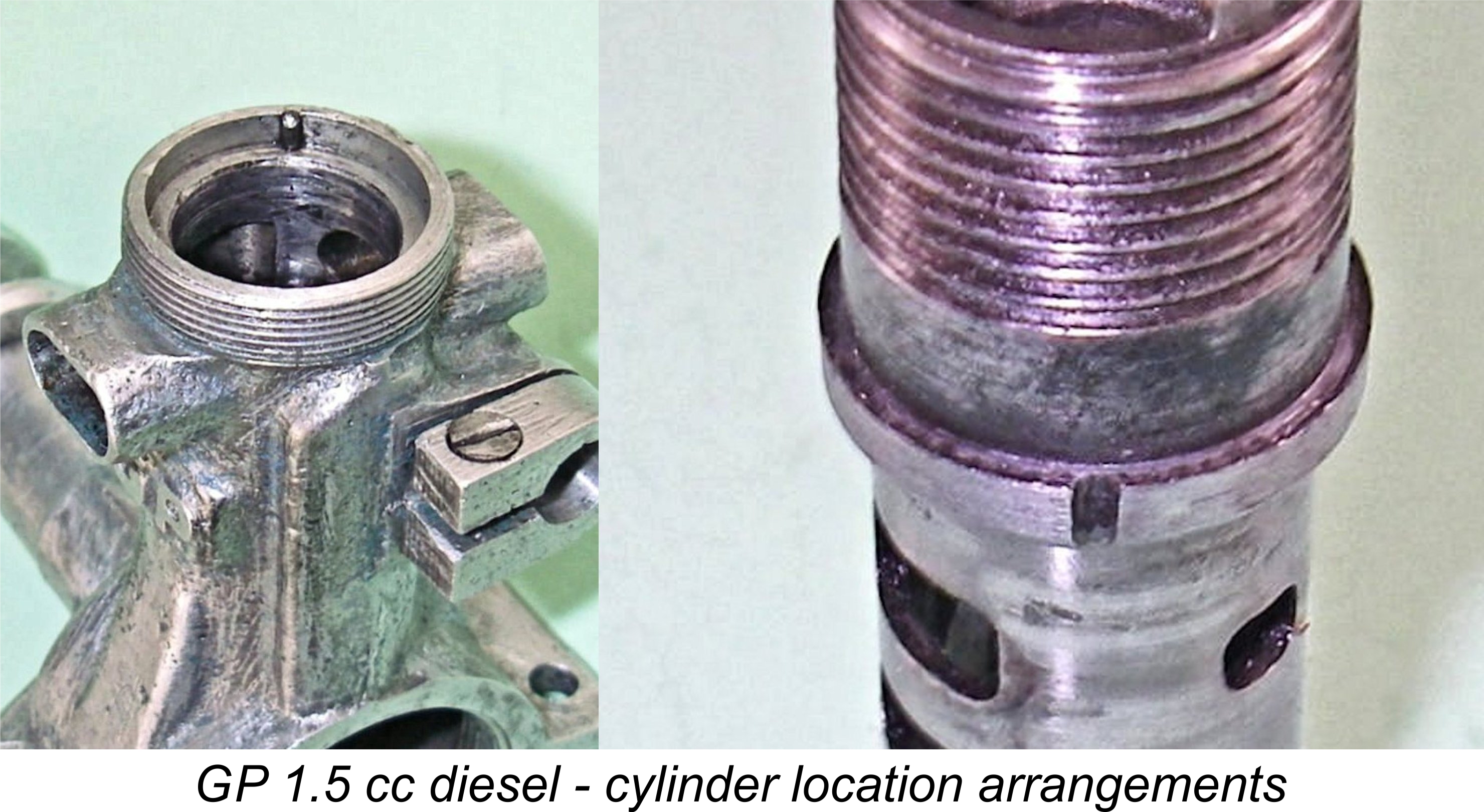 locating flange and its seat in the crankcase - since this location was well above all of the ports, such a gasket would serve no purpose. Like many other designs, the engine relies for its crankcase seal upon the cylinder being a close-fitting moderate push-fit in the crankcase. Crankcase compression is excellent.
 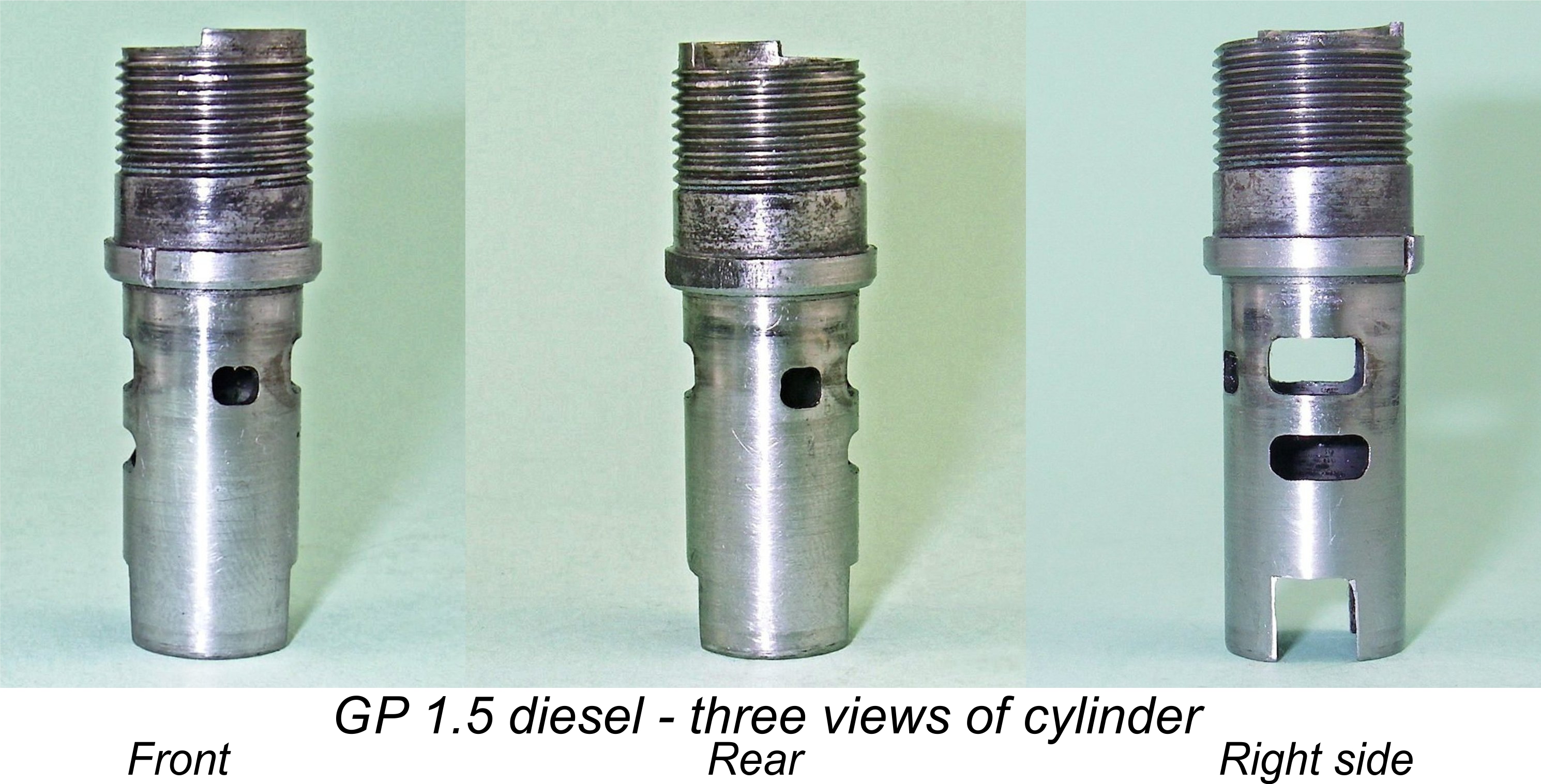 this arrangement clear. It should also clarify the point that the porting of this engine was amazingly advanced for a sideport diesel of any vintage, let alone a pioneering model like this.
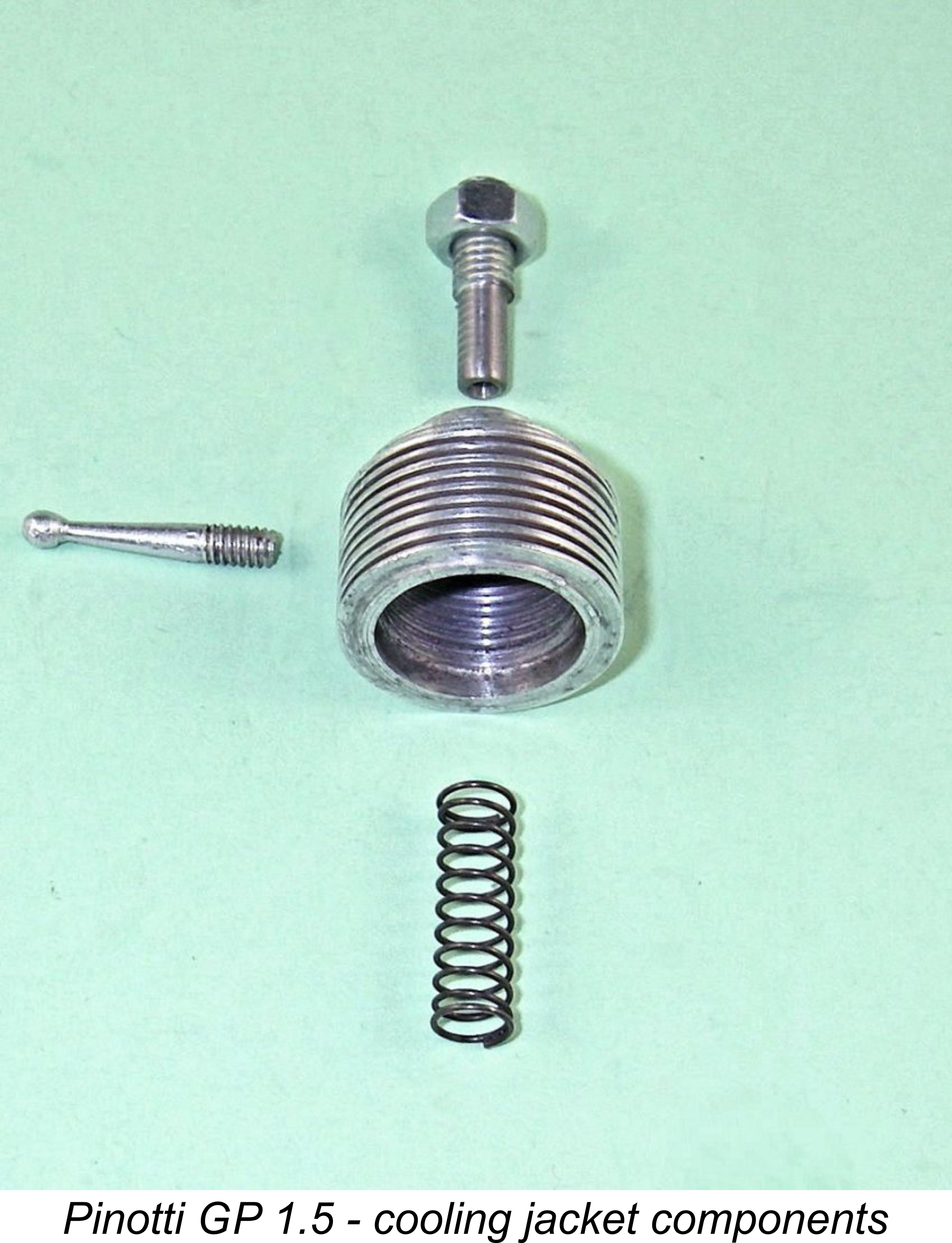 The compression adjustment system is assembled around an internally-threaded screw-on cooling jacket which is machined from what appears to be another gravity die-casting. This component is centrally drilled and tapped to accept a normal comp screw. However, the comp screw in this case is a simple slot-head screw with no tommy bar. This screw is equipped with a lock-nut to allow it to be locked to the cooling jacket so that the two components turn as one.
 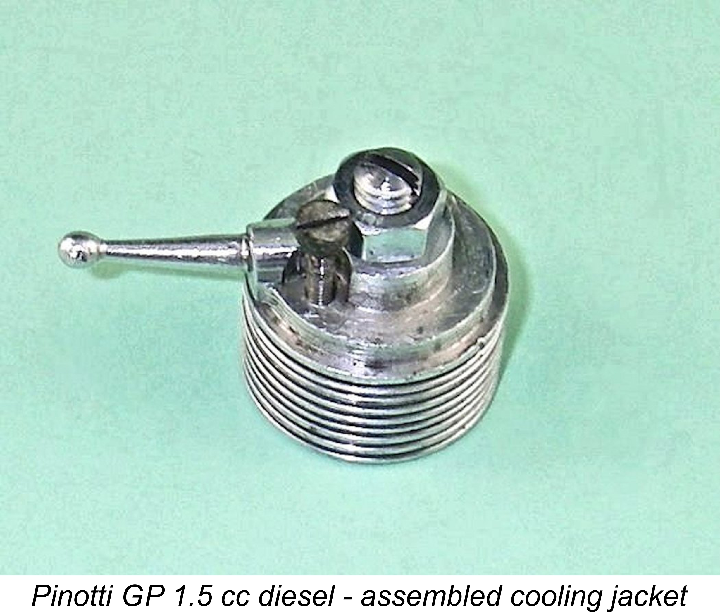 Before fitting the assembled cooling jacket to the cylinder, the final step is to add a coil spring which encloses the protruding inner end of the comp screw. The jacket is then threaded onto the cylinder and screwed down until contact is made with the top of the cylinder (as opposed to the contra piston, which the jacket alone cannot contact). One then backs off until the previously-mentioned 2 mm hole corresponds to the low portion between the two "steps" in the upper cylinder edge. At this point the 2 mm screw is turned down all the way, hence protruding into the low segment of the upper cylinder edge. In this orientation it acts as a stop to limit annular movement of the cooling jacket to that permitted by the stops. Both elegant and ingenious!
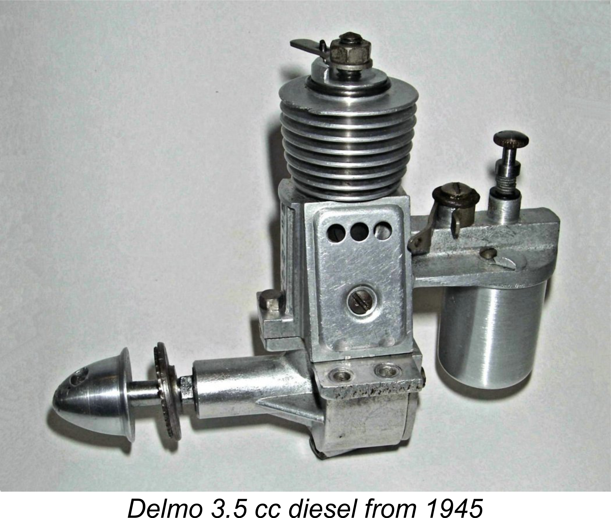 cooling jacket at the mid-point of its available movement, turn the comp screw back down to contact the contra piston and then tighten the lock nut. After this is done, the engine can be started and run using the cooling jacket alone for compression adjustment. Different fuels or loads could easily be accomodated through a minor re-adjustment of the central compression screw relative to the cooling jacket. Neat, or what?!?
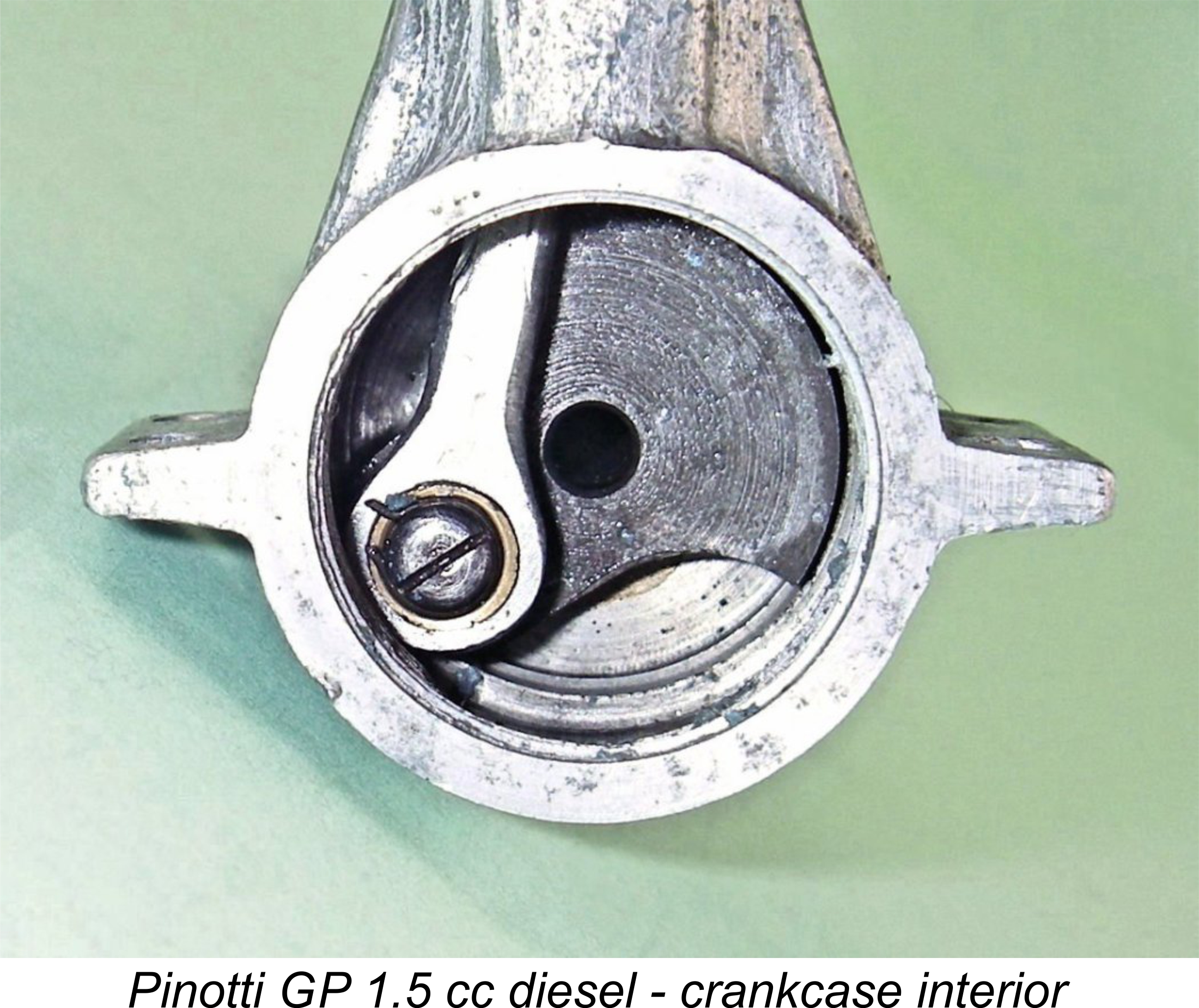 running off the end of the crankpin. The backplate has an annular recess machined into its inner face to accomodate the head of this screw. One assumes that the screw has a left-hand thread - beyond checking that it was tight, I elected not to disturb it given the uncertainty in that regard.
  thinking than either the Rogstadius model (which was in effect a Dyno clone) or the Västeråsdieseln 2 cc model. In many ways it's a far more sophisticated design than those engines, displaying relatively little infuence from any of them.
 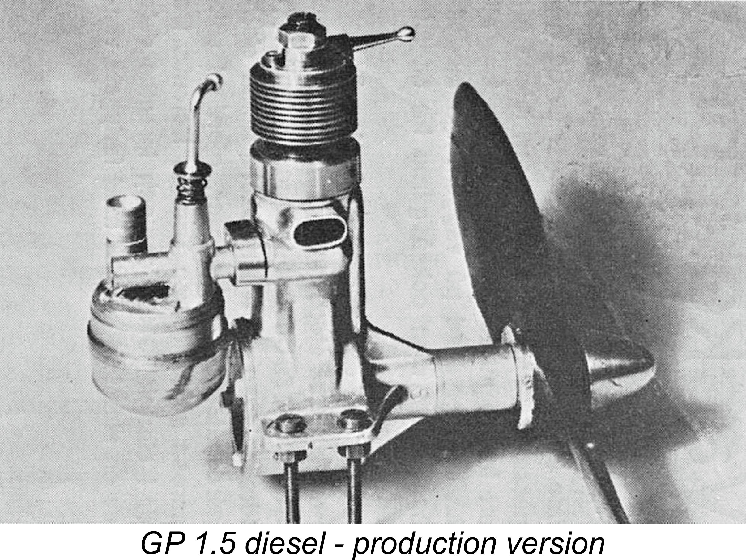 Although they were apparently able to sell their entire output despite this very high price, the level of production which could be sustained by the Pinotti family was woefully insufficient to provide them with a liveable income from model engine manufacture alone. It appears moreover that Carlo Pinotti had been unsuccessful in re-establishing himself in his former electrical engineering profession. In all probability he had simply been away from that profession for too long to remain abreast of the considerable advances in the field which had taken place in the interim period.
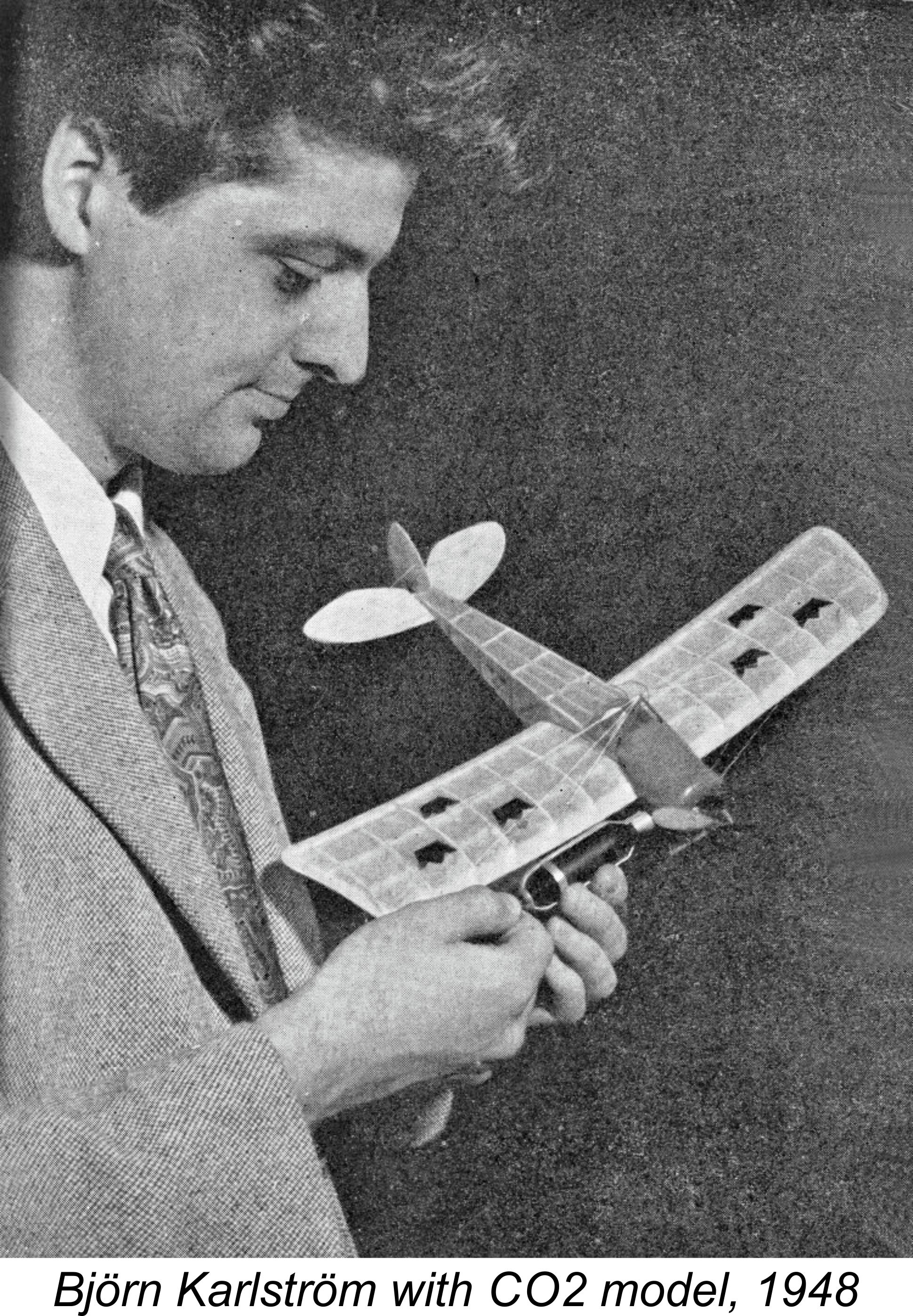 motorcycles, since he was earning additional money by repairing both motorcycles and motorcycle instruments such as speedometers, rev counters and the like. When the model engine manufacturing is factored in, it’s clear that life for Pinotti was rather busy!
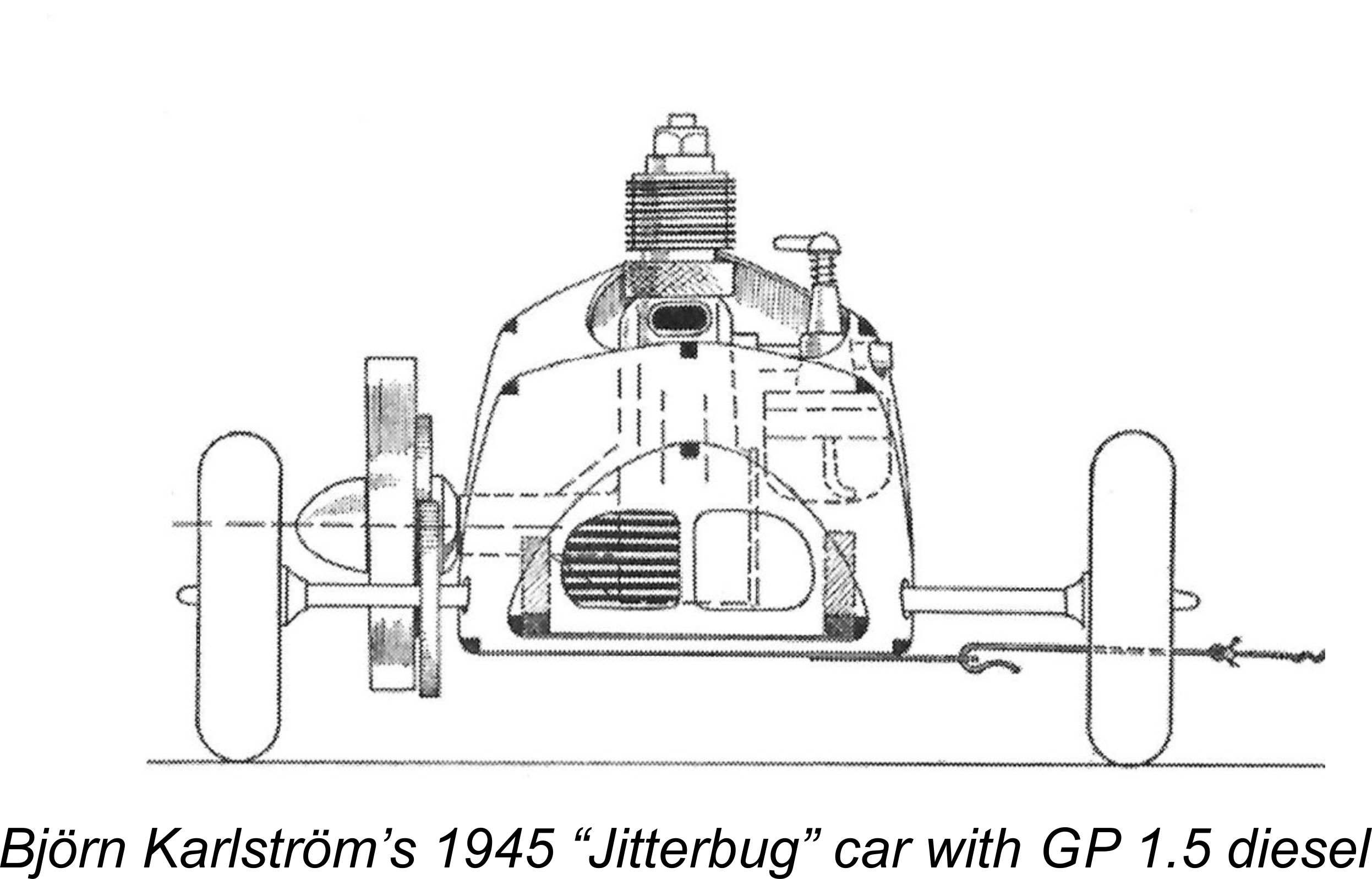 It appears that Pinotti toyed with the idea of expanding the GP range. There were reports that he was contemplating the introduction of a 4 cc model, and indeed a single prototype of such an engine was apparently produced. However, for reasons which will forever remain obscure, this project did not proceed.
 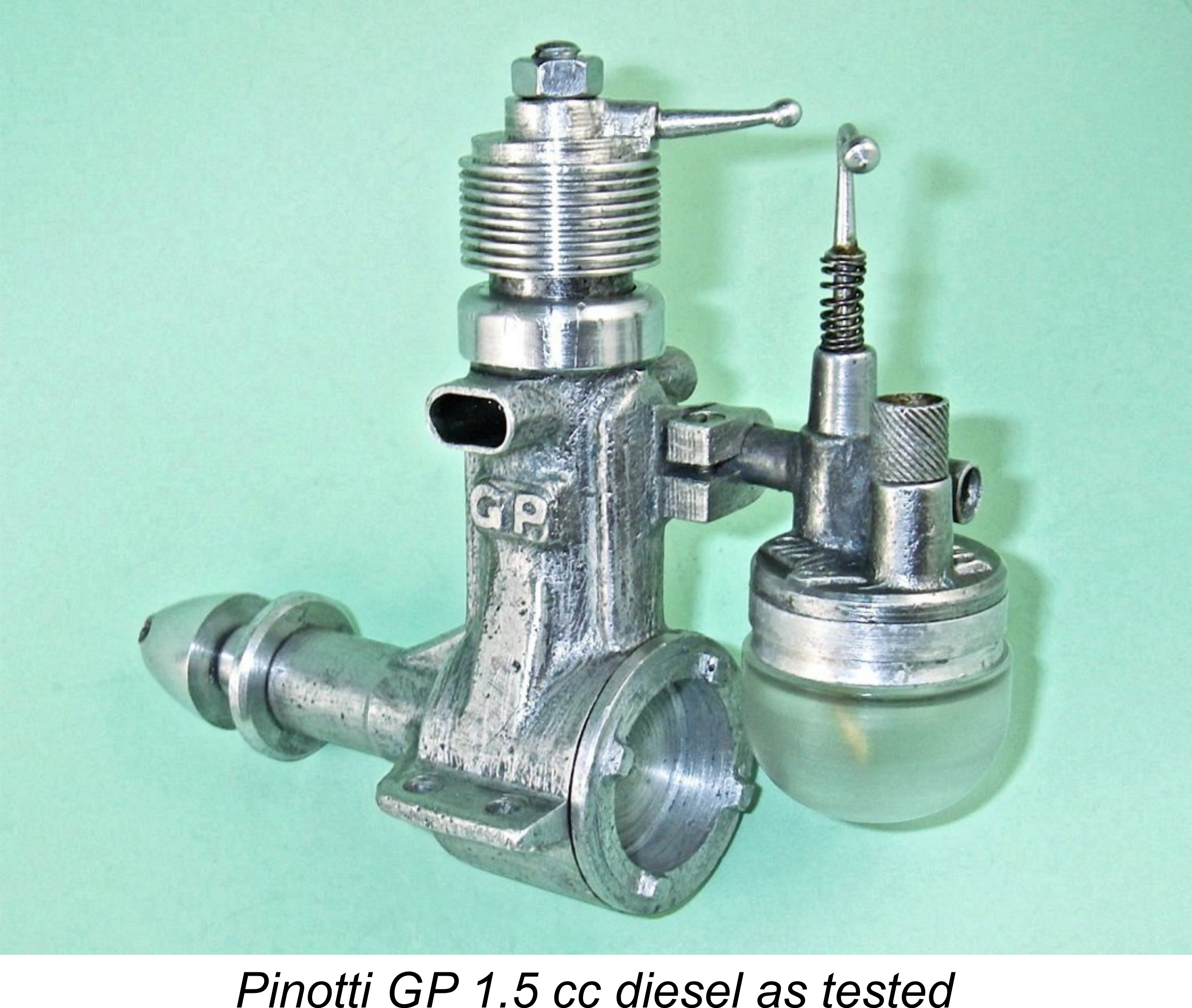 So few examples of the GP 1.5 cc diesel appear to remain in circulation that I saw my acquisition of a fine example of the engine as placing me under an obligtion to test it and share my findings with others. If those of us fortunate enough to acquire engines of this rarity simply hoard them without taking steps to share them with others to the extent possible, the engines and what they represent will in effect be lost to posterity.
  mid 1946 Mills 1.3 Mk. I quite a good run for its money. My notes from previous testing show that either a 9x6 or a 10x4 makes a very satisfactory prop for initiating tests on the Mk. I Mills - plenty of flywheel effect, and no chance of over-speeding. Accordingly, I started with props of that size.
 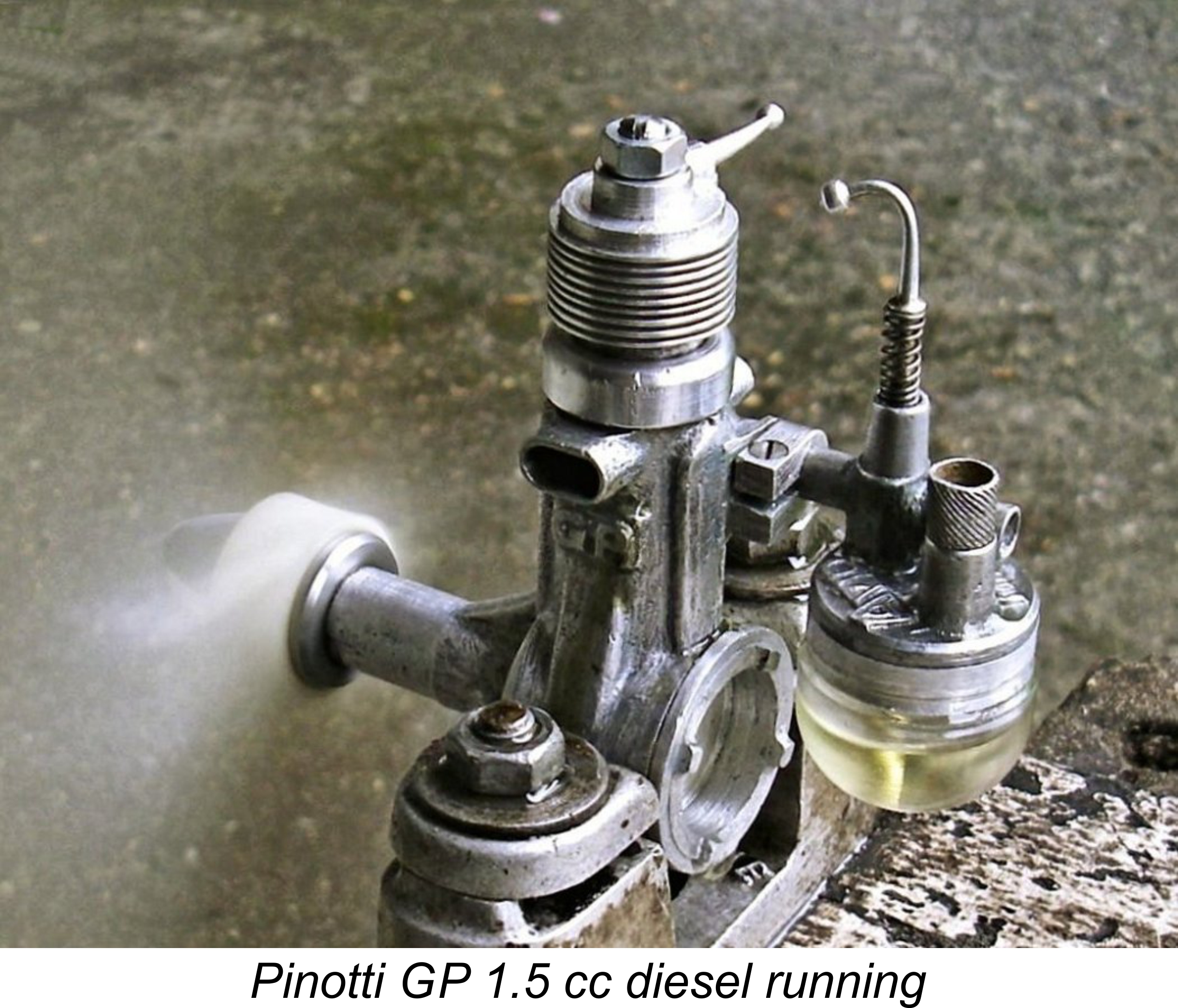 The GP 1.5 seemed to appreciate this approach! It fired on the third flick and then topped that by starting about three flicks later following a small increase in compression. As simple as that! It was over-rich and under-compressed, but it burbled away happily waiting for me to set things right.
  The Taipan 9x6 was turned at 5,400 rpm (c. 0.040 BHP) - a little faster than the Top Flite, just as expected. I then switched to 8x6 props. The rather "slow" Tornado 8x6 nylon prop was turned at 6,700 rpm (c. 0.062 BHP), while the Taipan 8x6 delivered 6,900 rpm (c. 0.063 BHP). Since the Taipan is a much faster prop than the Tornado, the very small difference in speeds led me to the conclusion that I was approaching the engine's peak at 6,900 rpm - not an unexpected finding for an engine of this early vintage. Anyway, I elected not to push for higher speeds - no sense thrashing an engine of this age and rarity at speeds beyond its peak!
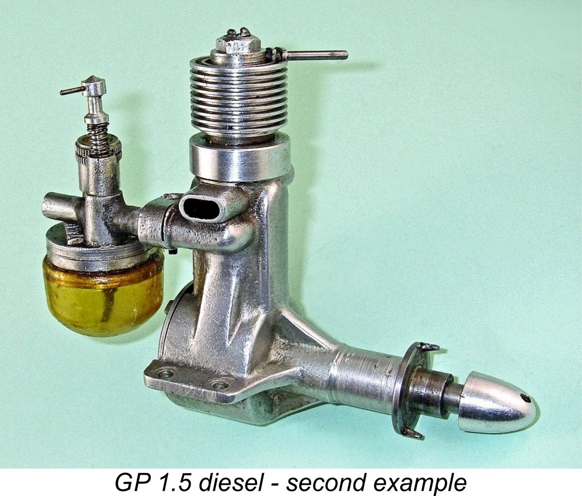
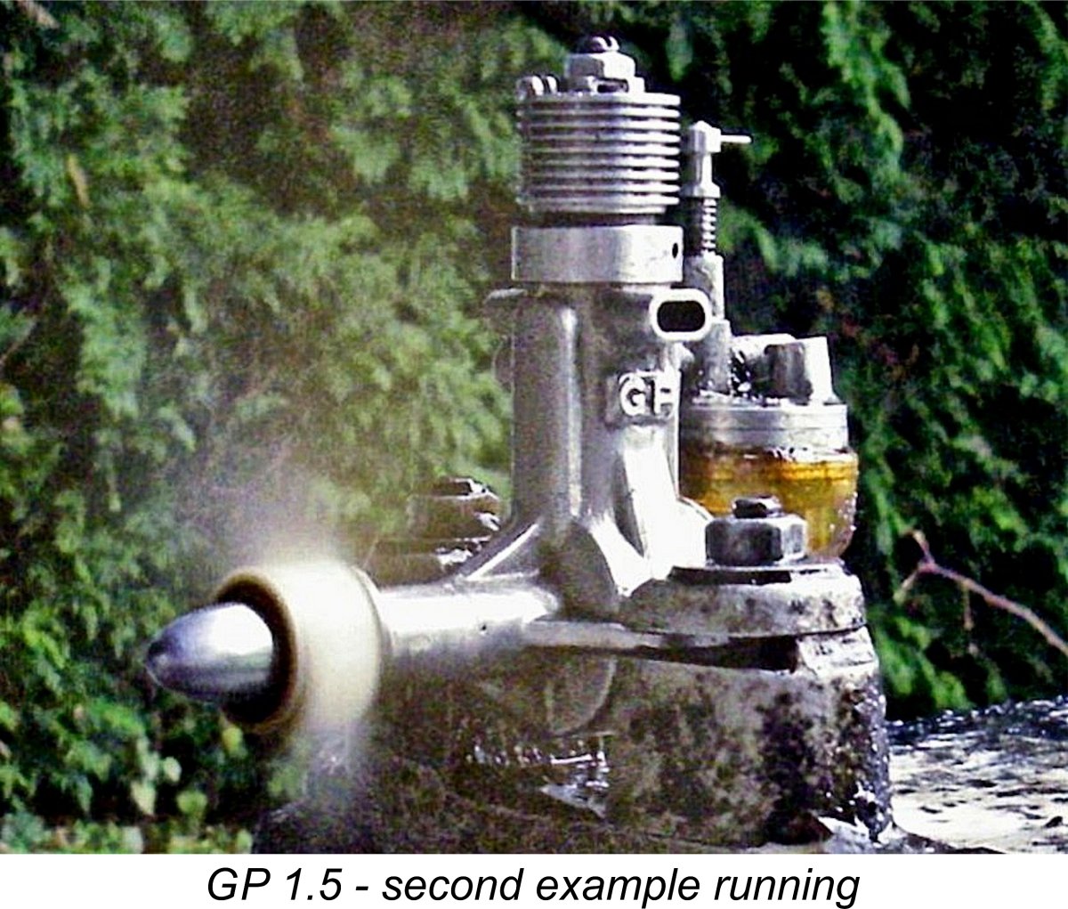
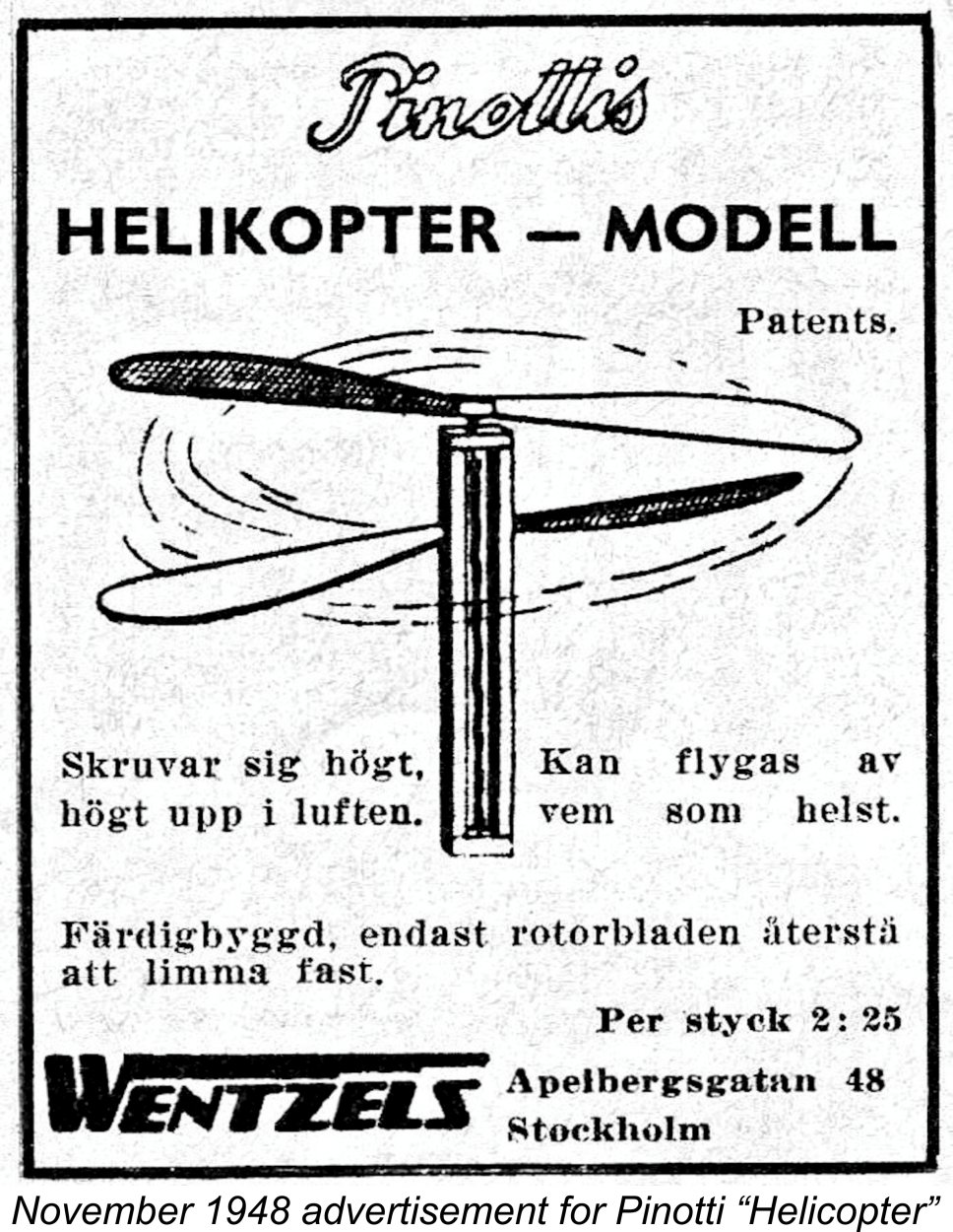 Pinotti evidently maintained his active interest in models throughout the mid to late 1940's. We don't know when production of the Pinotti 1.5 ended, but it was probably continued at some level up to the late 1940's.
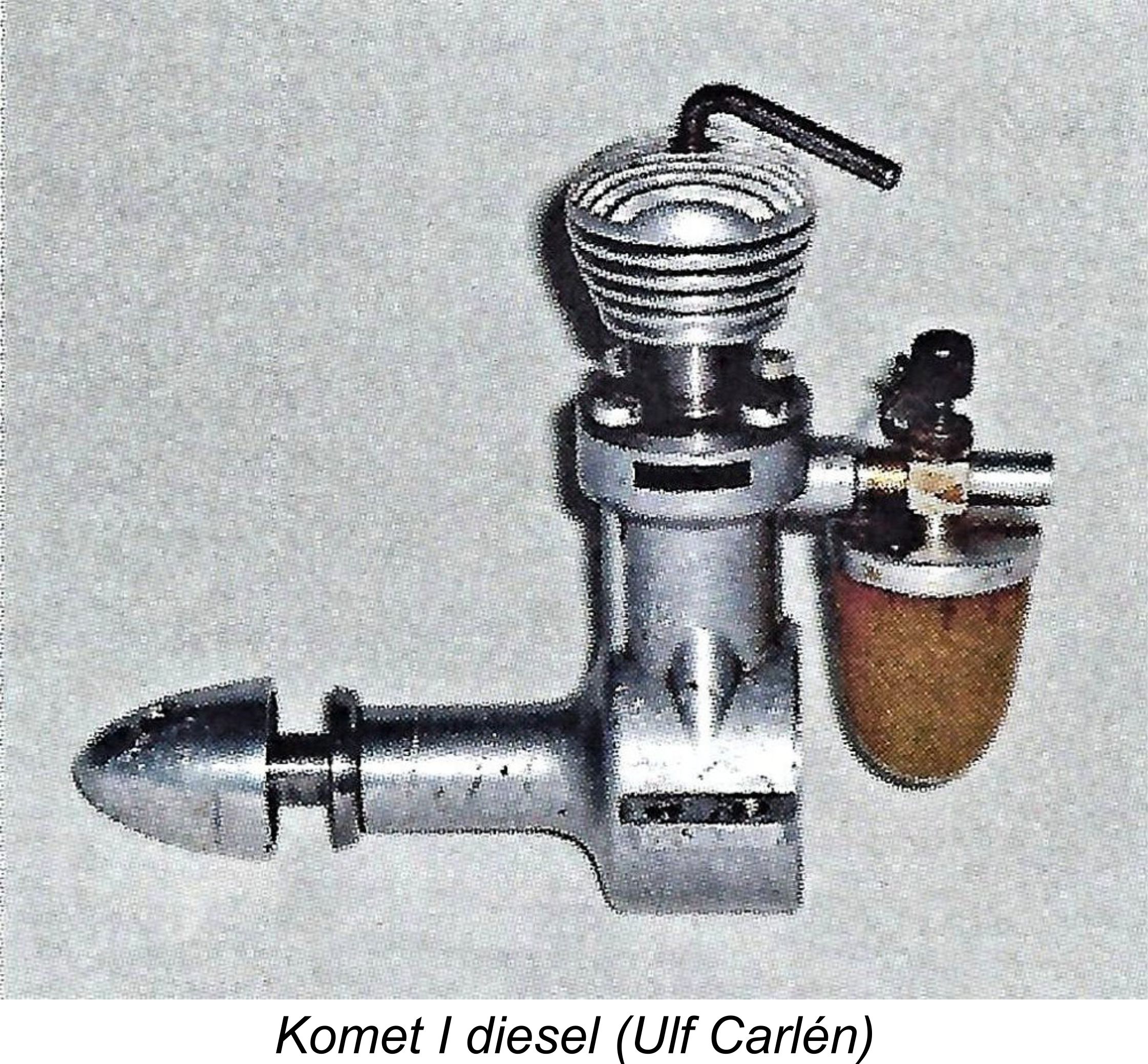 Pinotti's interest in venturing into fields other than model engine manufacture was most likely driven by the fact that as of the late 1940's
 diesel engine suitable for beginners, which was to be sold through the ESKADER shop at a more economical price than its predecessor. The resulting engine was Carlo Pinotti’s final design – the GP 1001 model. This model made its appearance in 1949.
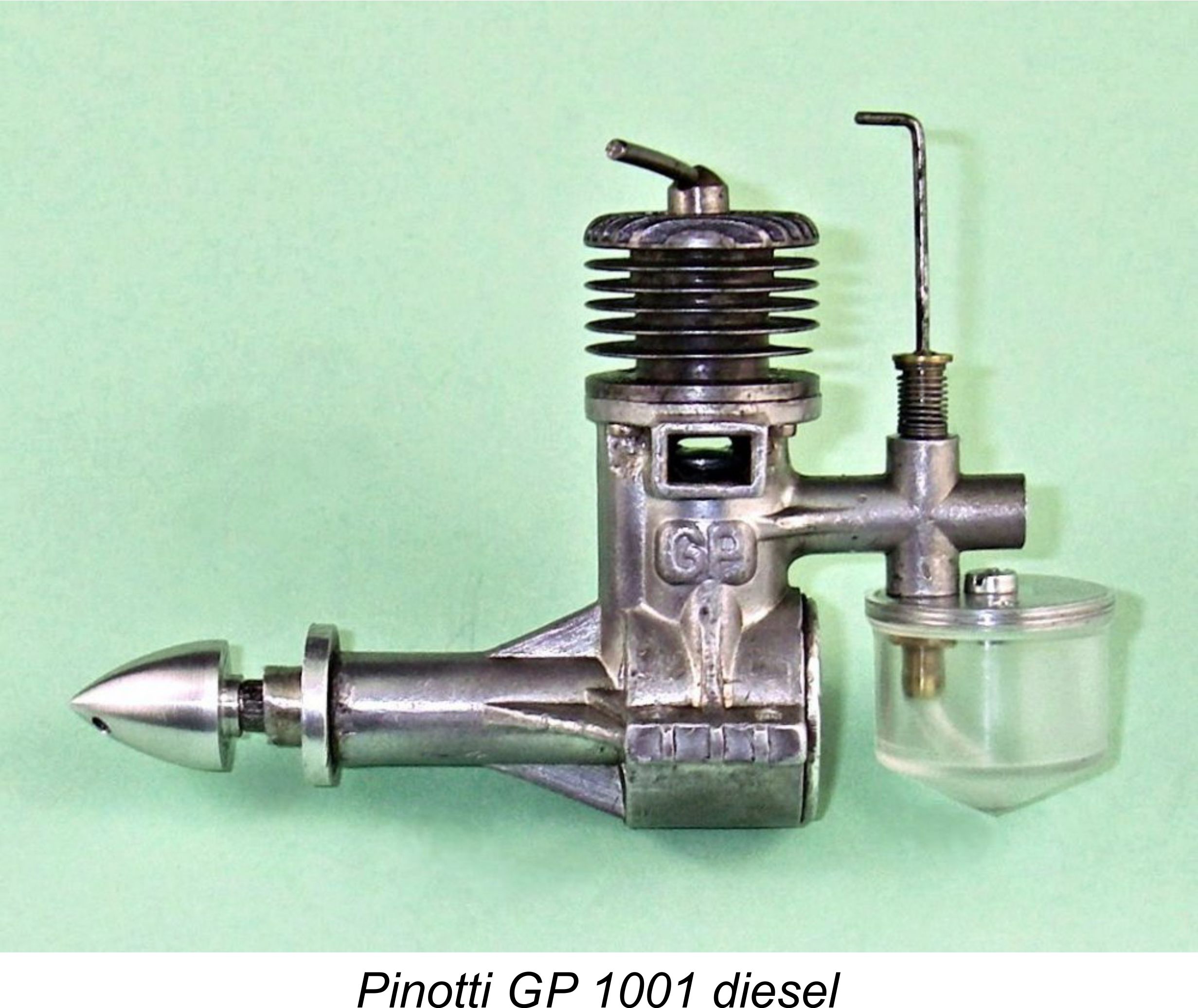 displacement. Bore and stroke of this neat and superbly-made little sideport design were 11.0 mmm apiece for an actual displacement of 1.04 cc (0.0.064 cuin.). The engine weighed a checked 96 gm (3.39 ounces) all complete with tank and spinner.
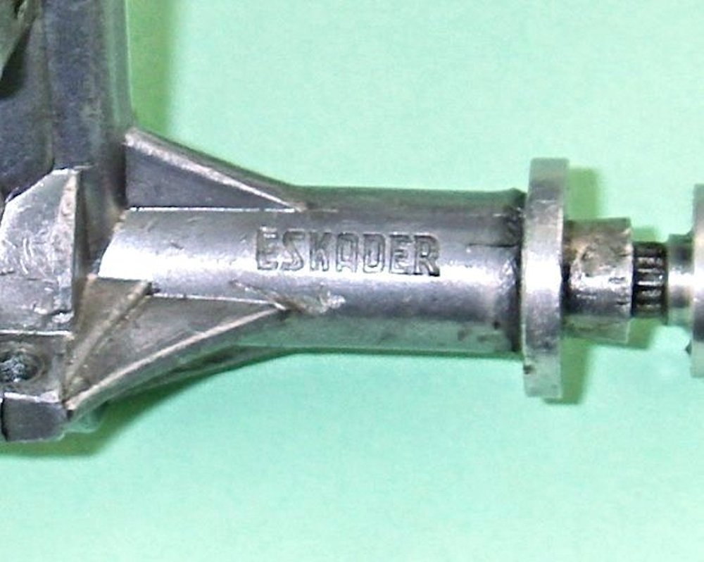 stamping was produced using a hardened steel tool that Peter's father had made himself. Amazingly enough, that tool still exists today (2015), being kept in the ESKADER shop! The labels of the boxes in which the engines were supplied also bore both the “GP diesel” and ESKADER names.
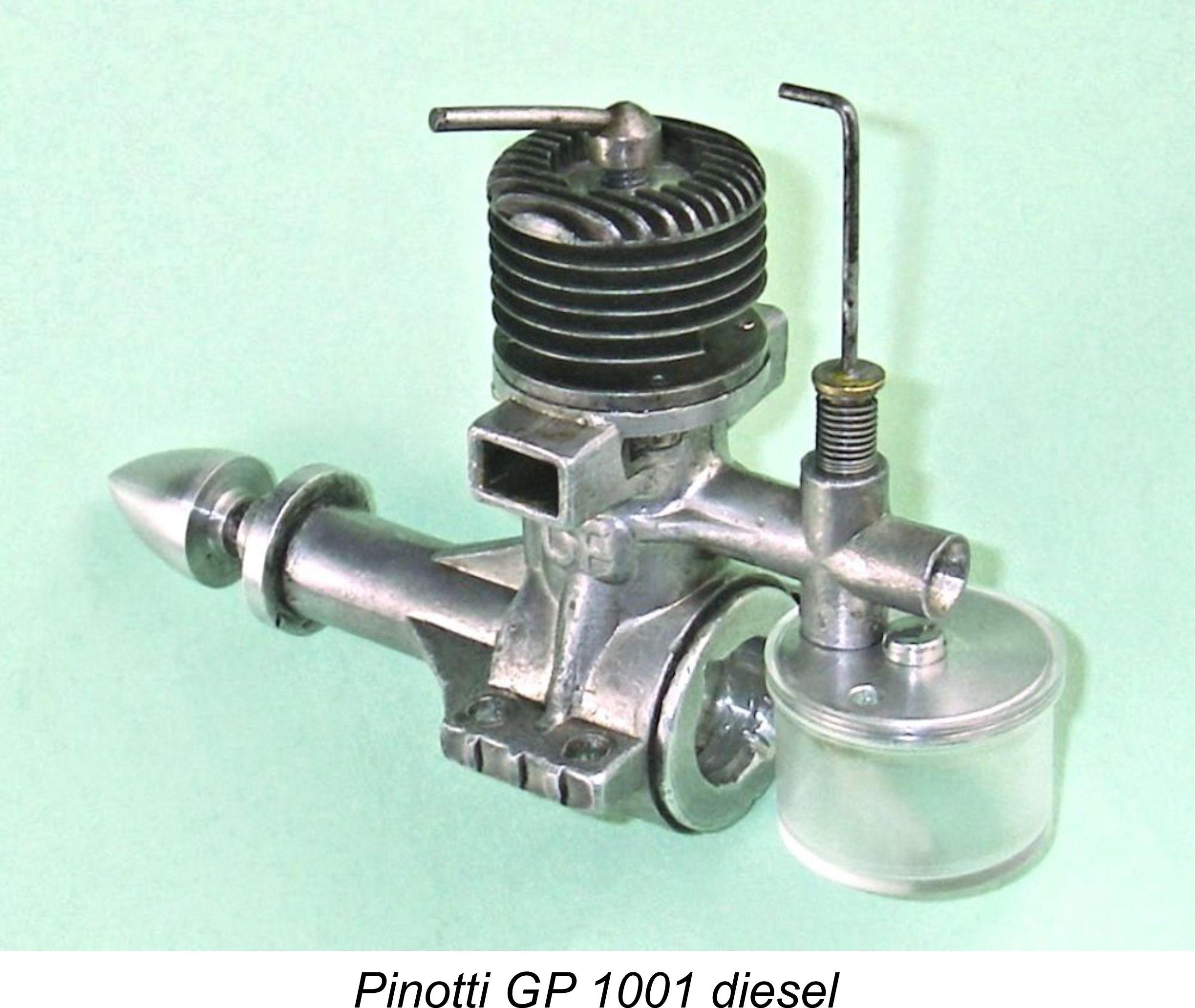 from-below approach was forced upon the Pinotti design by the presence of the integrally-formed cooling fins and the consequent impossibility of inserting the assembly screws from above. It has to be admitted that the Pinotti approach makes for a very clean and elegant if somewhat “fiddly” assembly.
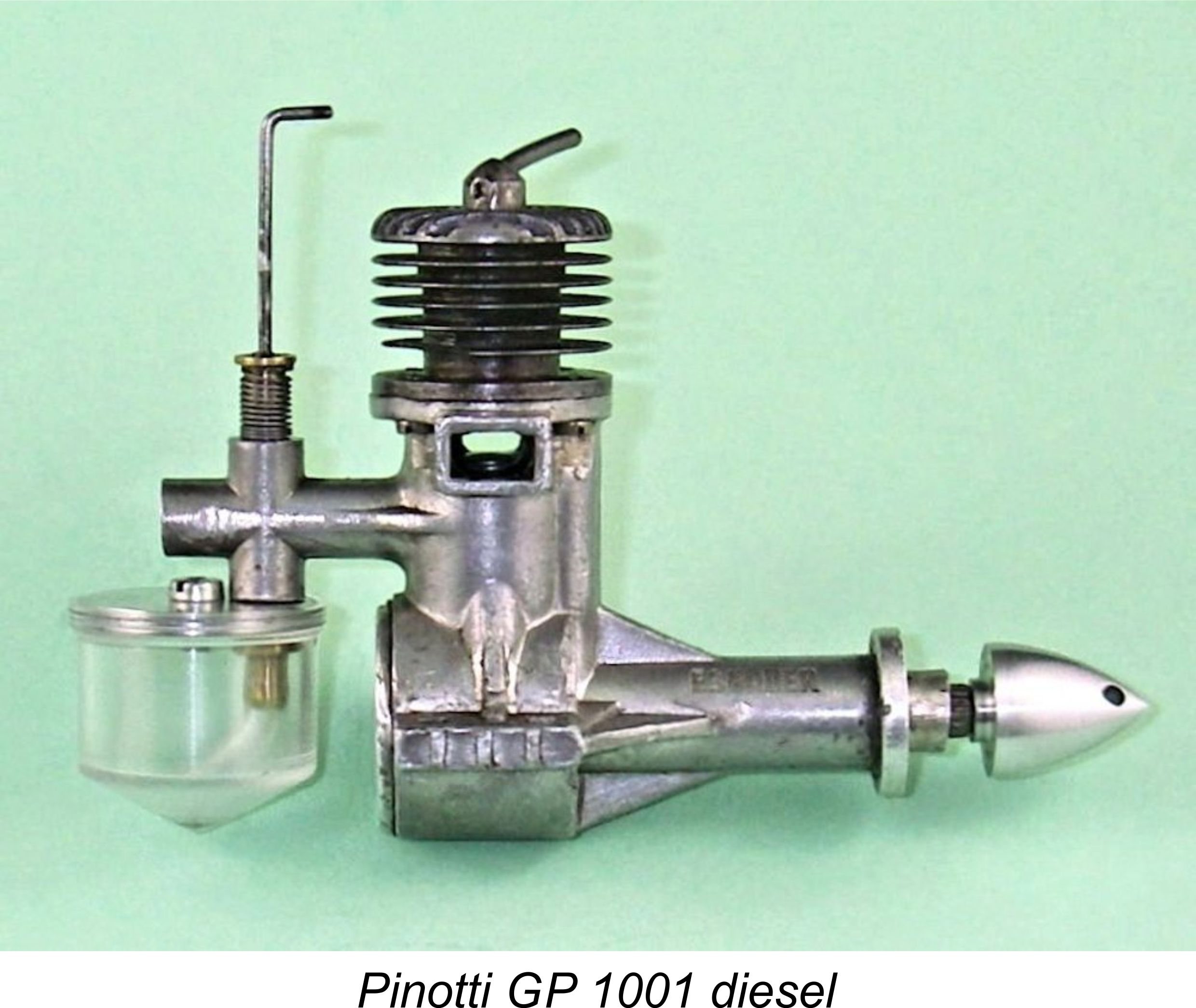 Although it has a very different external appearance, an internal examination of the GP 1001 reveals that its functional arrangements are very similar indeed to those of the Mills .75 and 1.3 models which had become overwhelmingly popular since their introduction. Cylinder porting is identical, with two drilled holes at the rear serving as the induction ports and two similar drilled holes at the front performing the transfer function. The transfer ports are supplied by a cast and internally milled bypass passage formed at the front of the crankcase. Again like the Mills, the exhaust chores are handled by a pair of oval-shaped ports of generous proportions, one on each side. These feed into integrally-cast exhaust stacks.
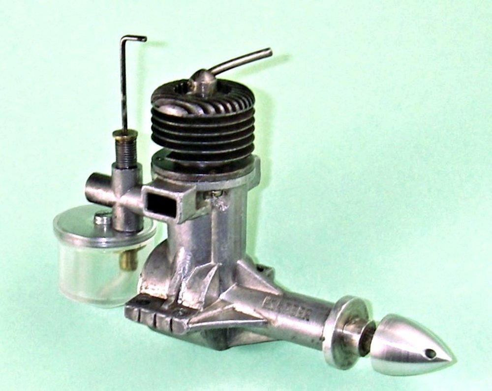 The two significant functional departures from the Mills design are the omission of the deflector step in the front of the cast iron piston crown and the use of integrally-turned cooling fins on the hardened steel cylinder liner instead of the screw-on alloy jacket used on the Mills models. The integral fins might be expected to promote superior cooling in the case of the GP model.
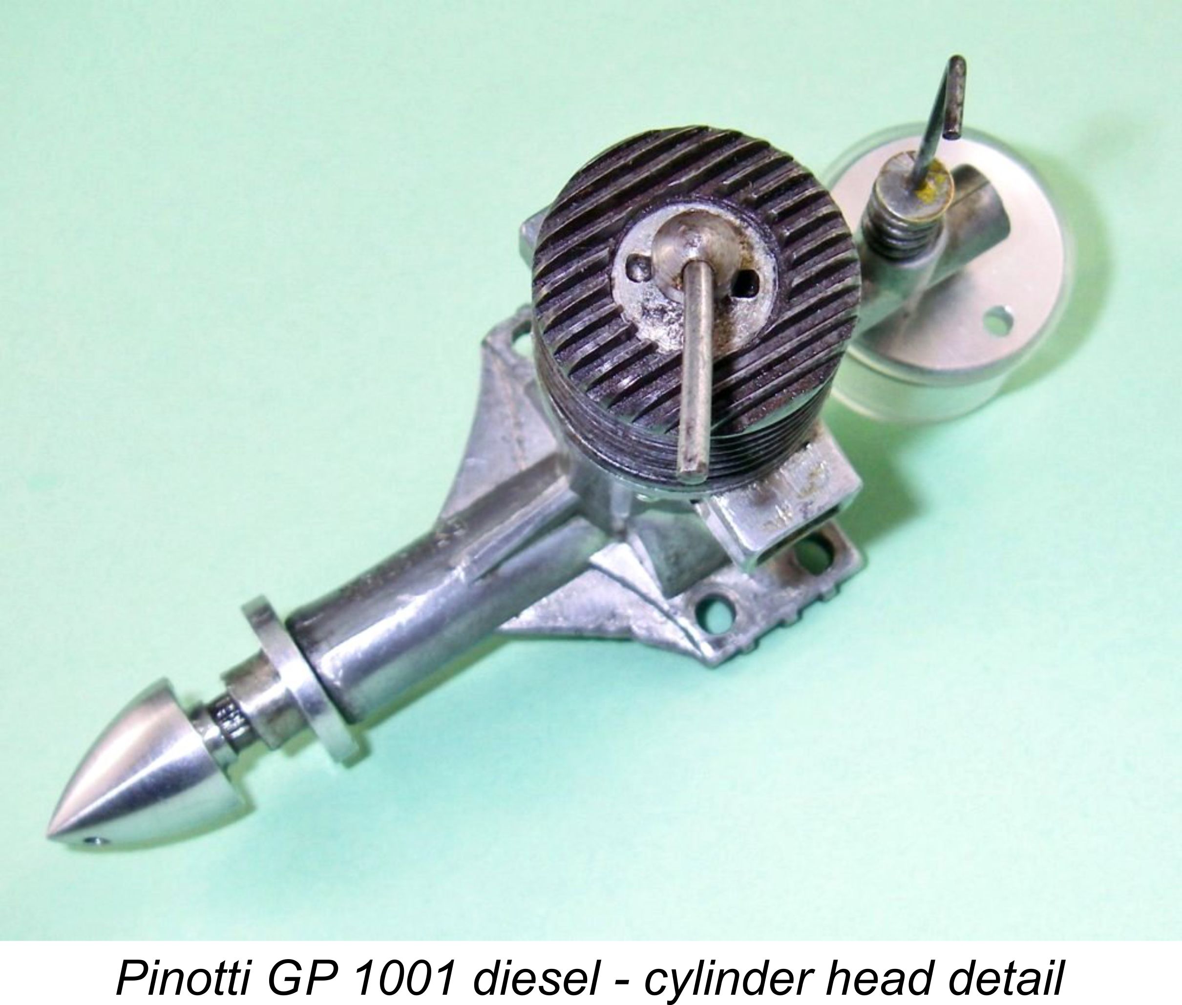 The cylinder was recessed at the top, with an internal thread being cut at a somewhat greater diameter than the bore. The contra-piston was inserted into the bore, after which a separate externally-threaded head button of aluminium alloy was screwed into the threaded recess above the contra piston. This button carried the central threaded hole for the compression screw. It was provided with a pair of holes with which a suitable pin spanner could be engaged for tightening. Elegant, but a complex production challenge, all of which was carried out to a superb standard.
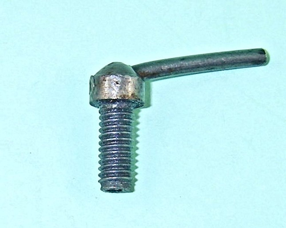 than usual. It had a “mushroom” head which had a greater outside diameter than the thread by which compression was adjusted. This design greatly improved the stability of the compression lever mounting, besides which the streamlined cap with its single-arm lever gave the top of the engine a very elegant appearance.
 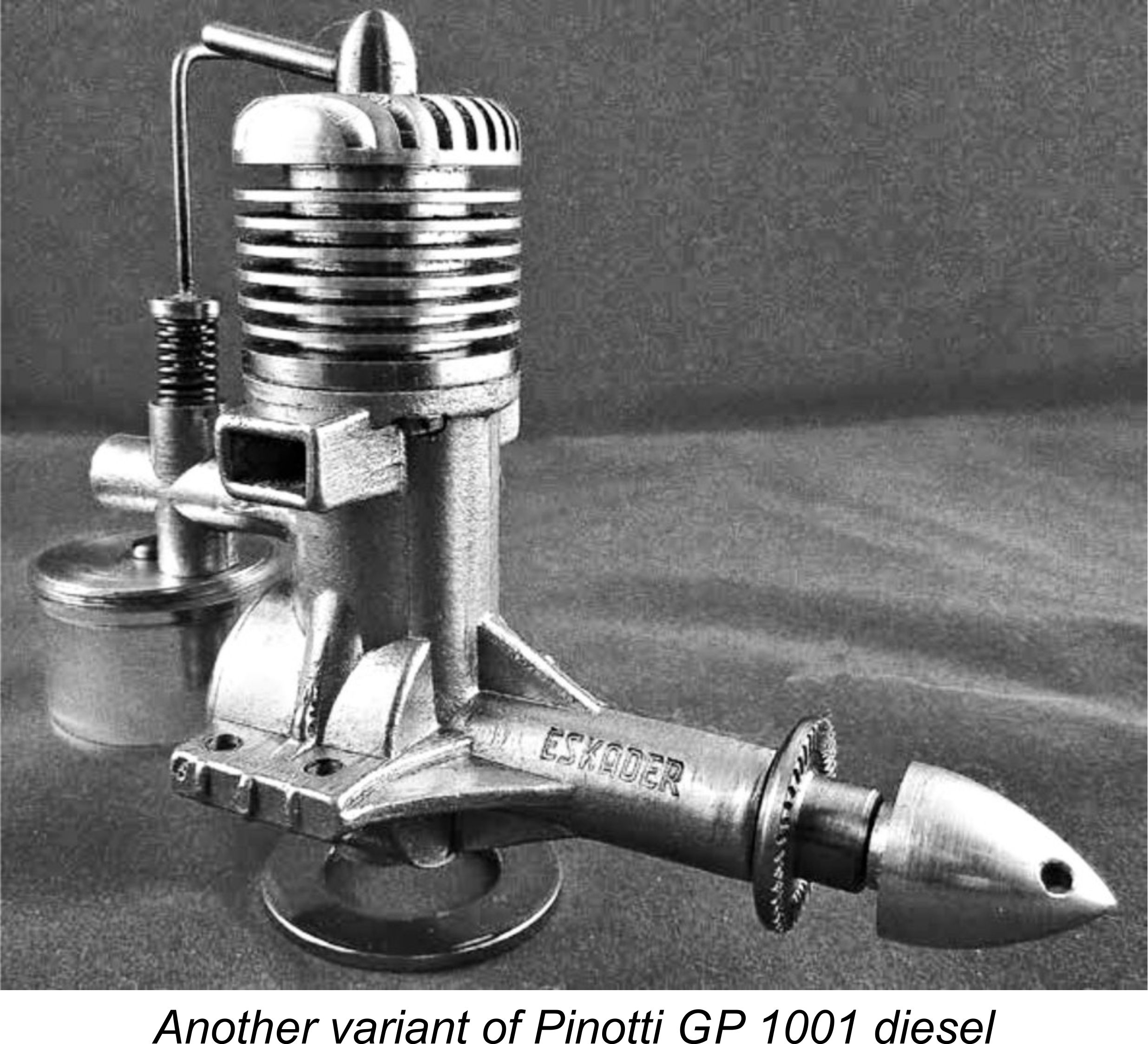 As with the earlier Pinotti engines, the fact that each engine was in effect individually produced meant that variations between individual examples were easily and not infrequently incorporated. A number of variations on the basic theme have been seen, notable different cylinder finning and head styles, different prop mounting hardware and various compression screw profiles.
 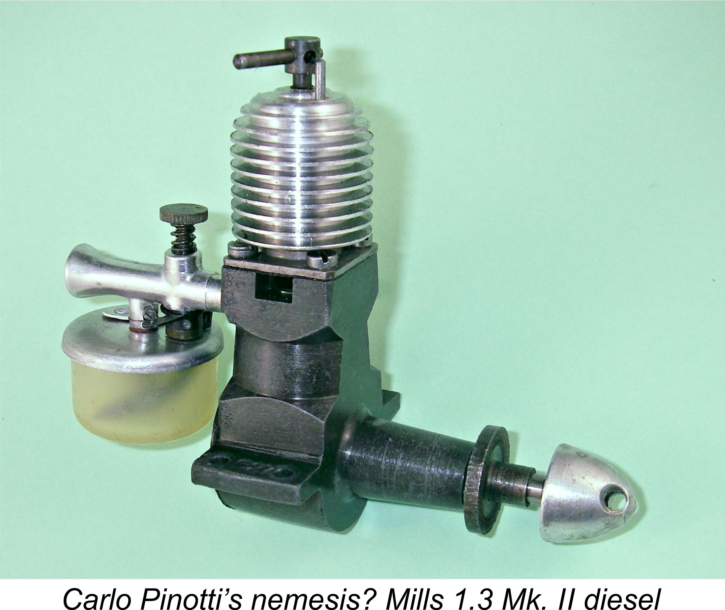 The death knell of the GP engines was sounded when the English Mills and E.D. engines began to penetrate the Swedish market in quantity beginning in around 1950. The individually hand-made high precision GP engines could not compete with these mass-produced offerings, especially in terms of price and ready availability. Carlo Pinotti was not prepared to lower his standards to permit higher and hence more economical levels of production, instead making the decision to abandon model engine manufacture once and for all in late 1950 or perhaps early 1951.
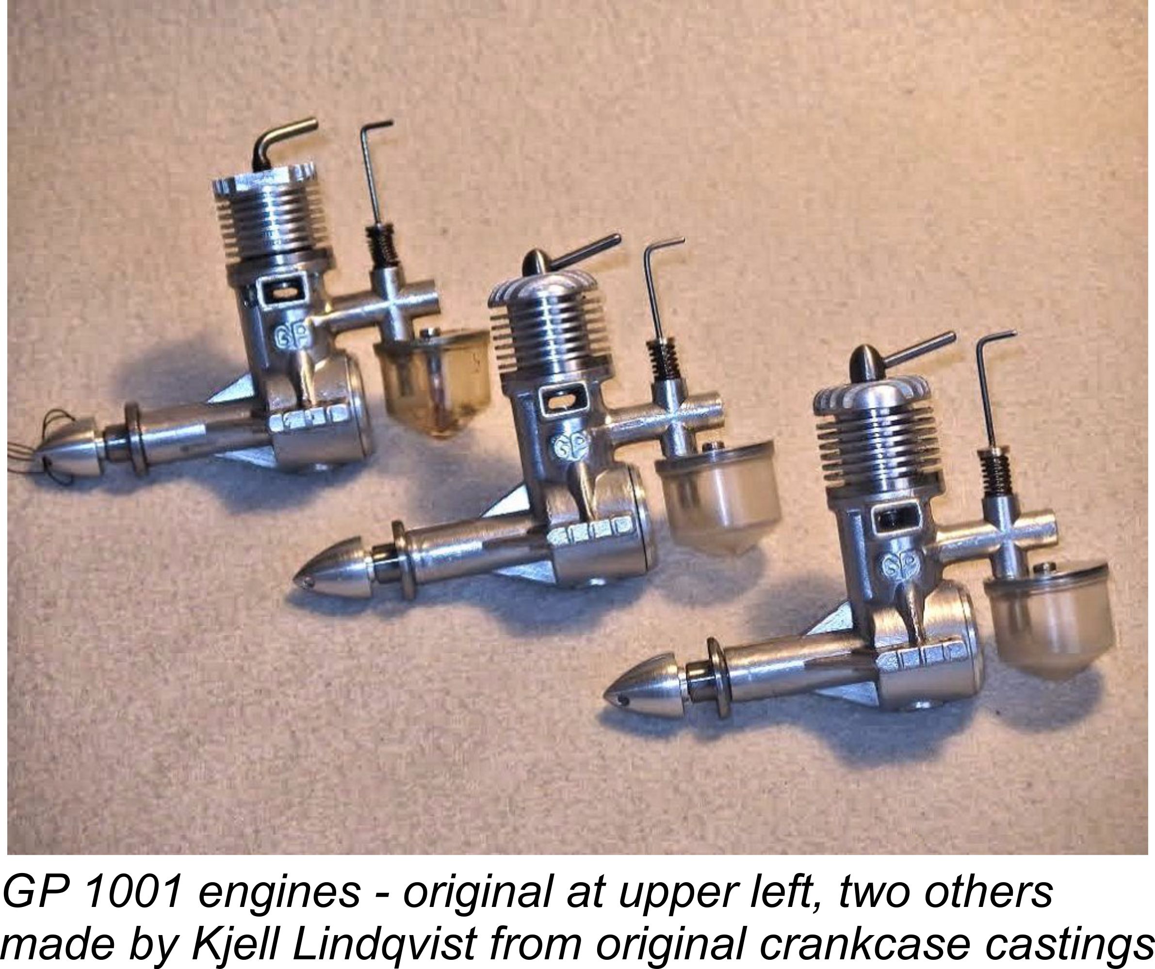 By all accounts, Pinotti continued to earn his living both as a musician and as a repairer of motorcycles and related equipment, still working from his back-yard workshop at Åsögatan 81 in Stockholm. He also seems to have returned to his musical instrument-making roots by making and repairing such instruments on a commercial basis.
 As mentioned earlier, Mario Pinotti became a pilot with SAS, working for the airline in that capacity from 1953 until he retired in 1987. During his career as a pilot, the aircraft that he flew included Metropolitan, SE 210 Caravelle, DC8, Boeing 747 Jumbojet, DC10 and finally DC9, on which he advanced to the position of Flight Captain. He ended up logging some 22,000 hrs in the air!
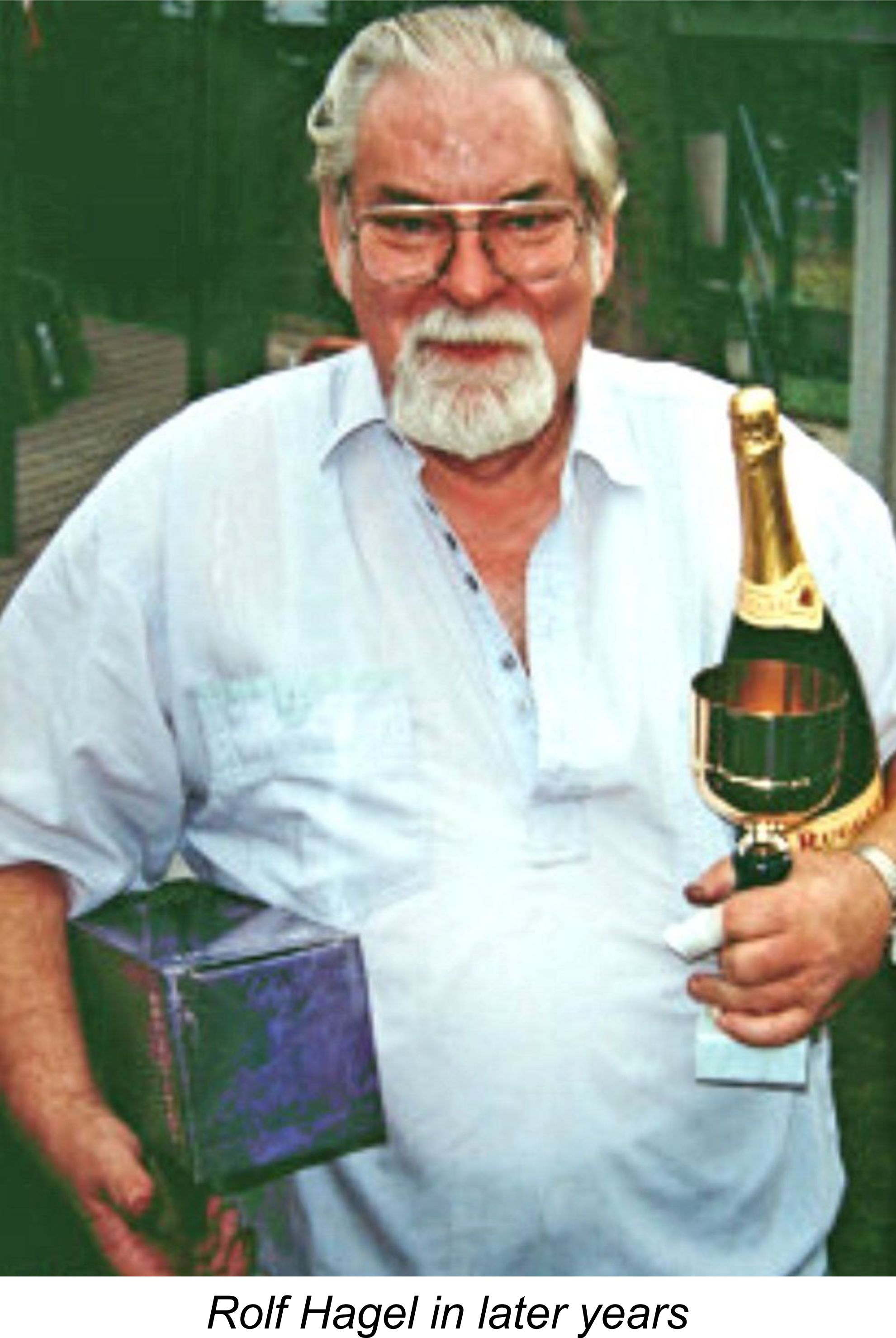 winning performances came about solely because their glides started at double the altitude of anyone else’s!!
 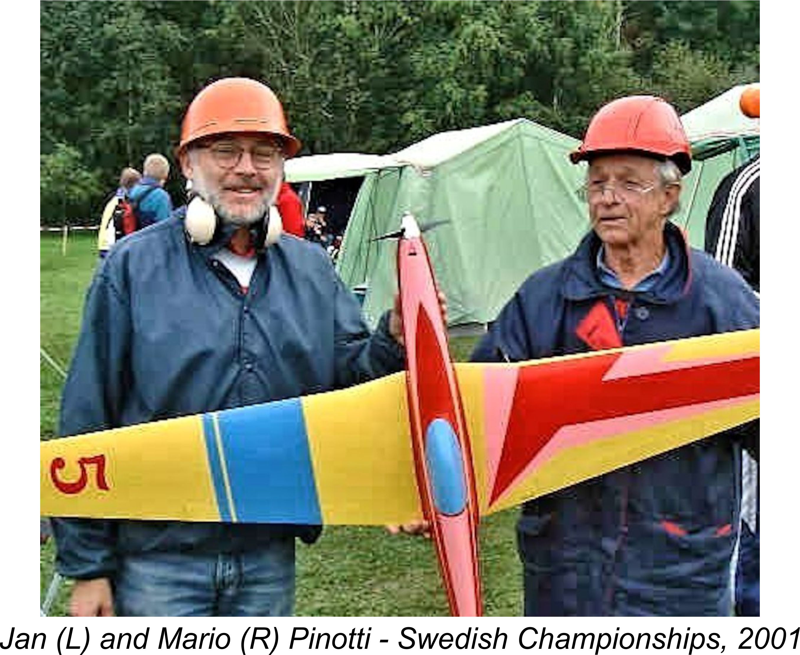 died in 2006 after a long and distinguished career in various fields of modelling.
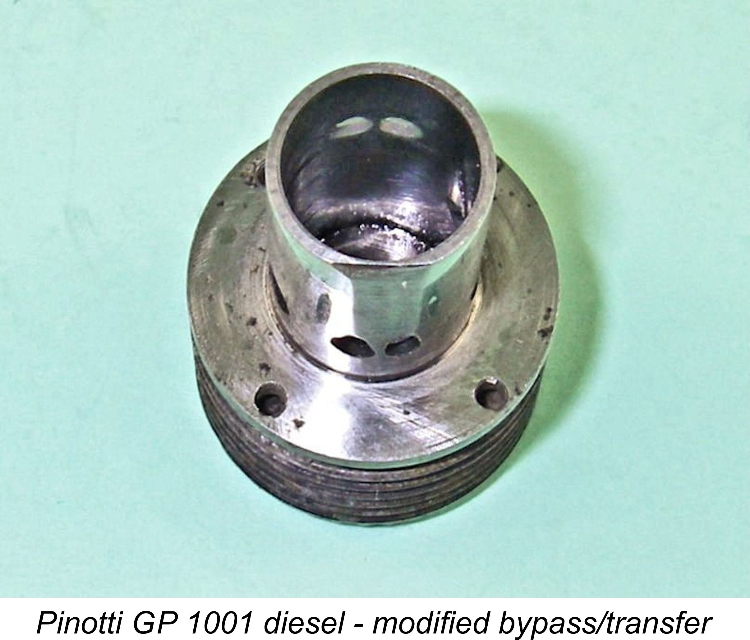 This example of the engine cannot be considered as completely stock – some previous owner has attempted to extract more power through the opening up of the bypass and transfer systems. A flattened area has been formed in the front of the outer cylinder wall below the transfer ports to increase bypass capacity to the extent possible, while the two transfer ports themselves have been externally chamfered to ease the passage of gas through them and encourage it to enter the cylinder in a more vertical direction in the absence of any form of deflector.
  slightly as well, extending them both upwards and downwards. The effect of this work was to slightly extend the exhaust opening period as well as increase the exhaust port area. The timing of both induction and transfer ports was left unaltered. The standard to which all of the described modifications have been carried out is in no way comparable to that displayed in the rest of the engine, making it certain that these are owner modifications rather than experiments by the Pinottis themselves.
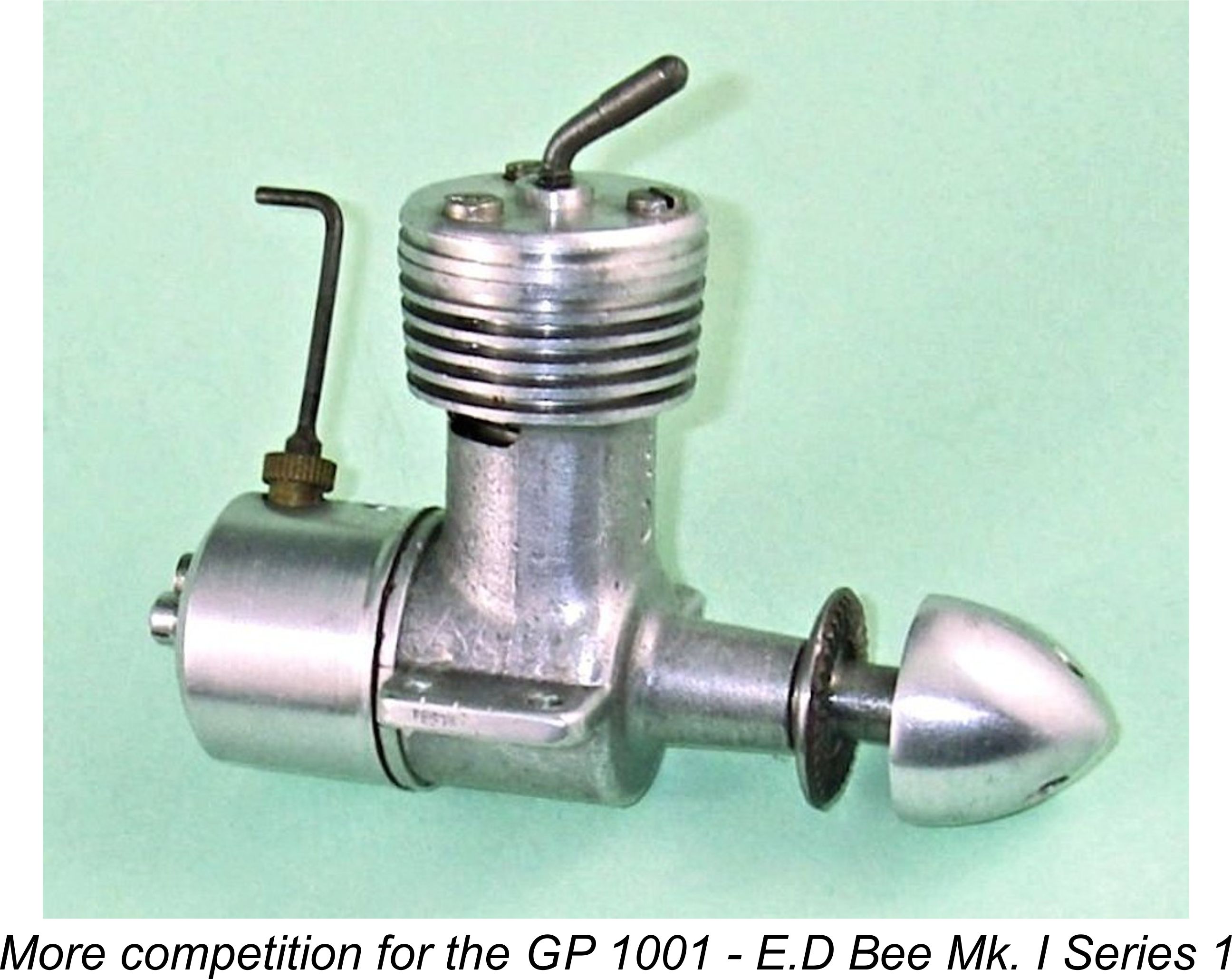 GP engines was the
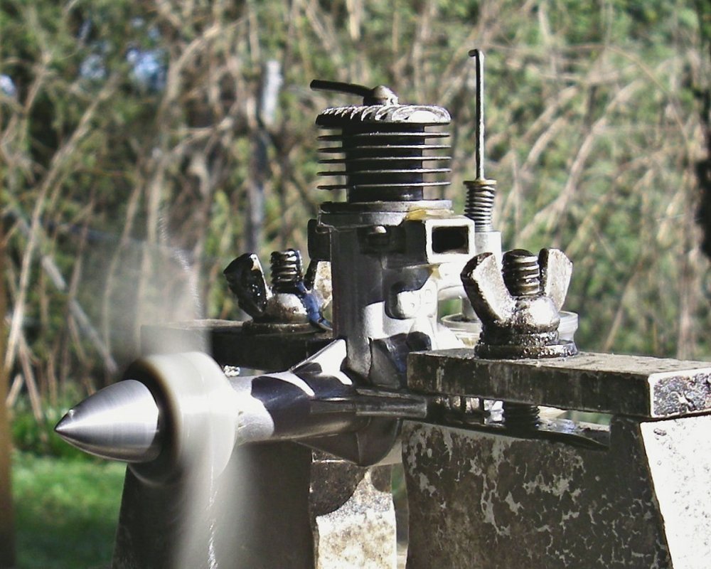
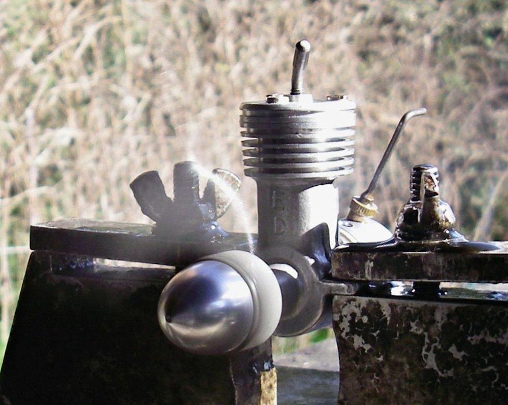
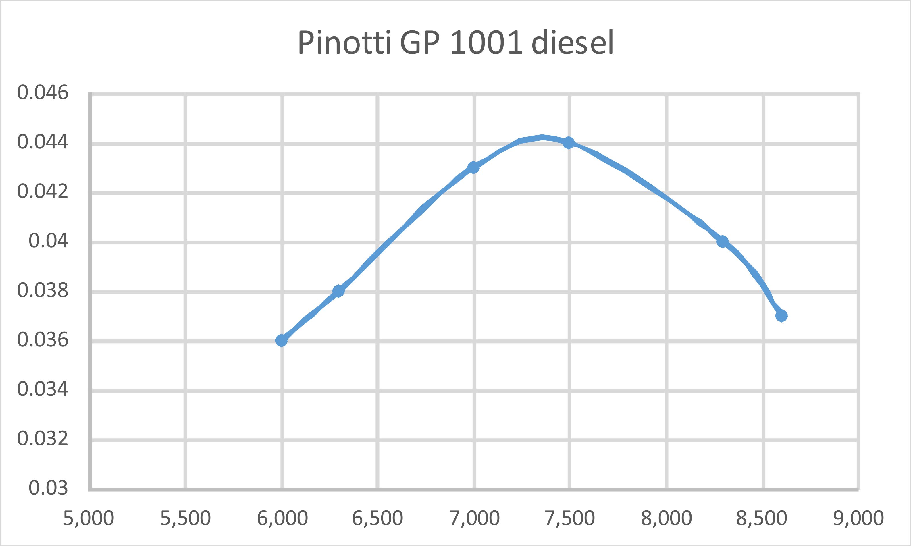
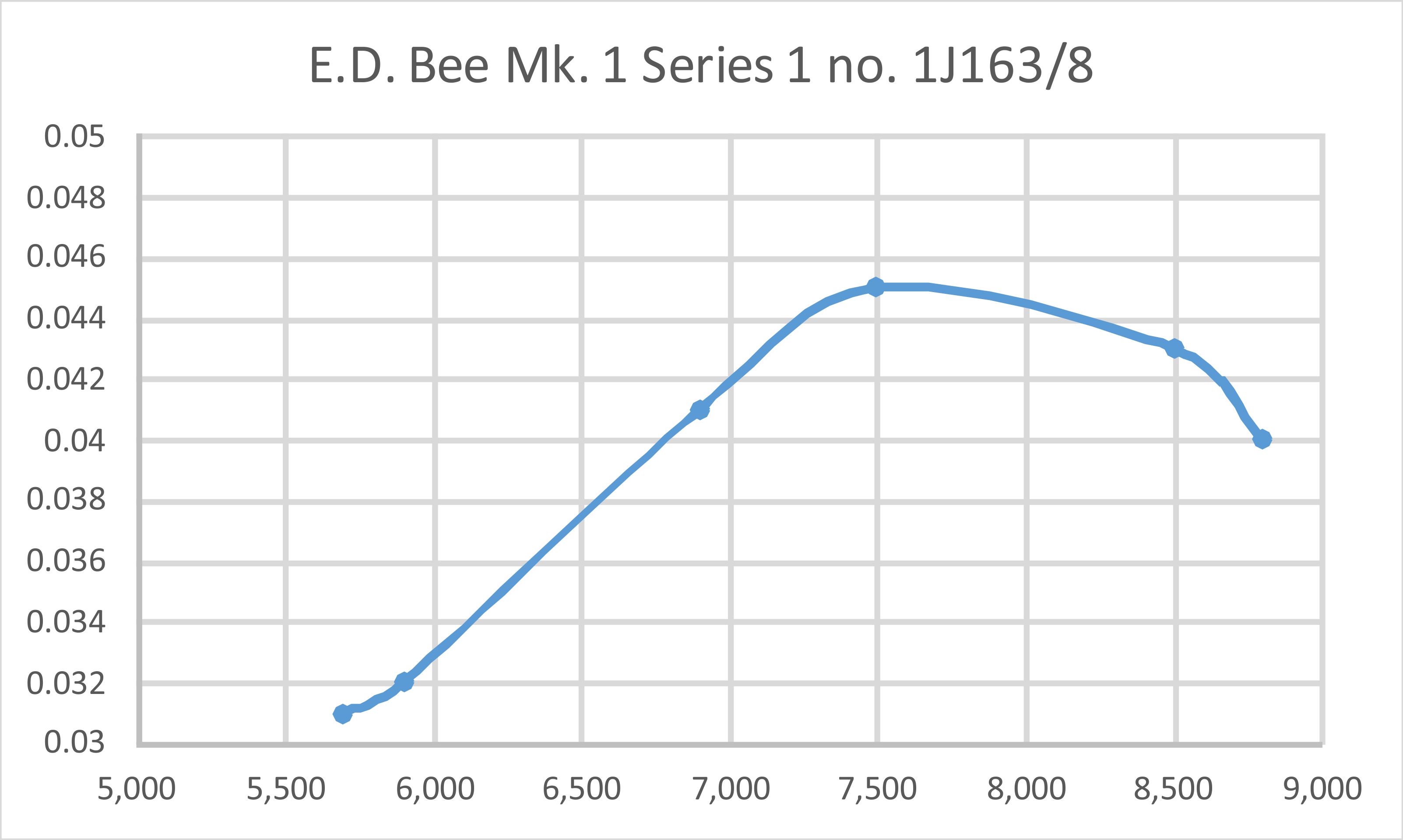
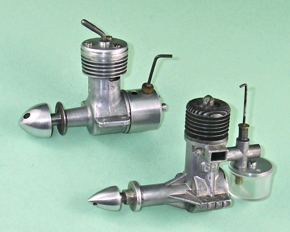 The measured performance of the GP 1001 is actually somewhat down on that reported by Peter Chinn and confirmed by later testing for the competing Mills .75 model. Chinn managed to extract 0.054 BHP @ 11,000 rpm from the smaller and lighter engine. However, the GP peaks at a far lower speed, hence being able to swing a substantially larger prop. This would give it a considerable advantage in many real-world situations.
 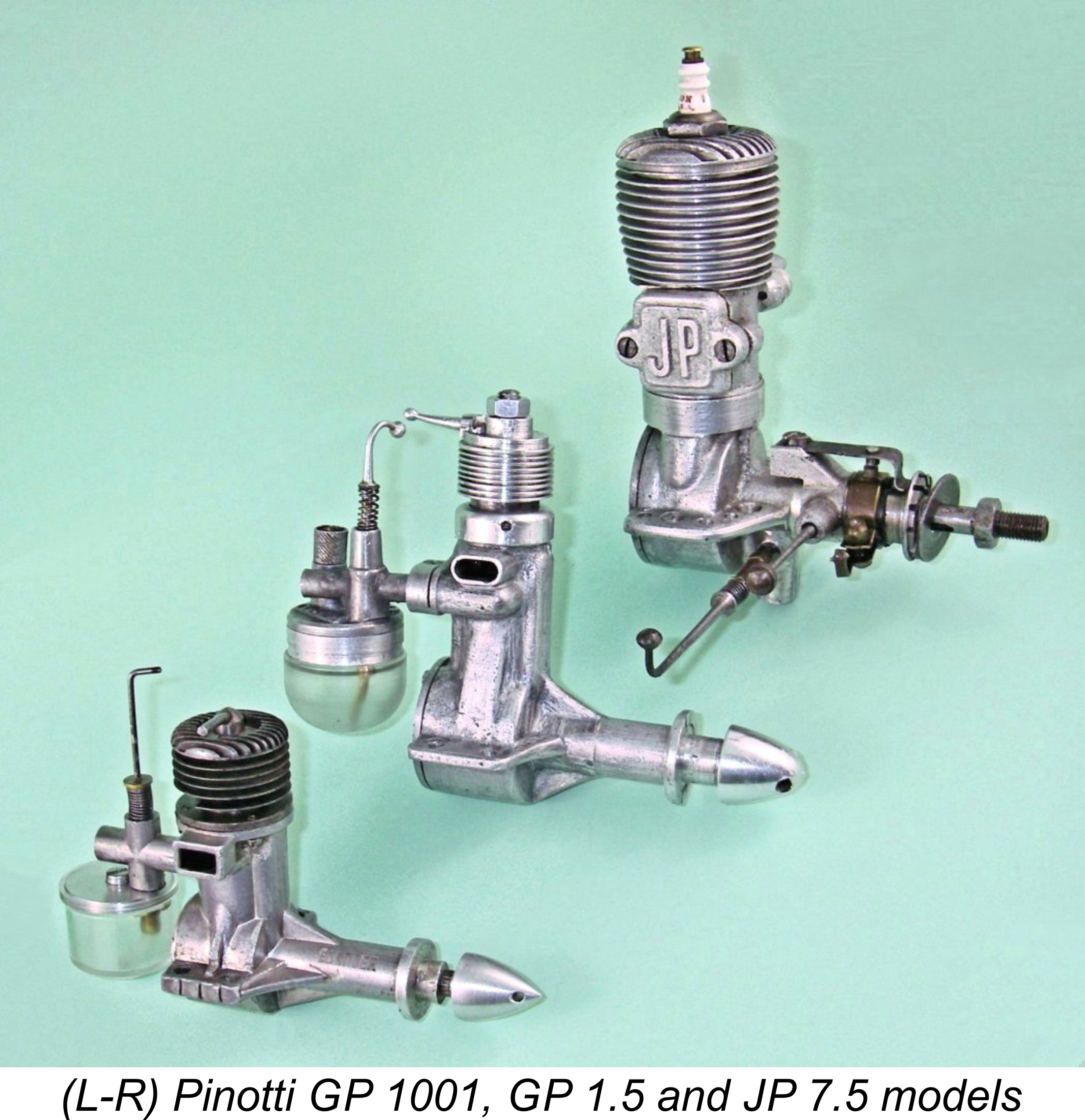 It must surely be clear to all readers that this is a story that would not (and indeed could not) ever have been told in the English language without the development of a collaboration between an English–language writer having a keen interest in the subject and a group of individuals within Sweden itself who were both able and willing to provide the required information, material and data. It has been my privilege to enjoy just such a collaboration with a number of such individuals, to whom I have already expressed my sincere appreciation. I can only hope that the finished article meets their expectations!
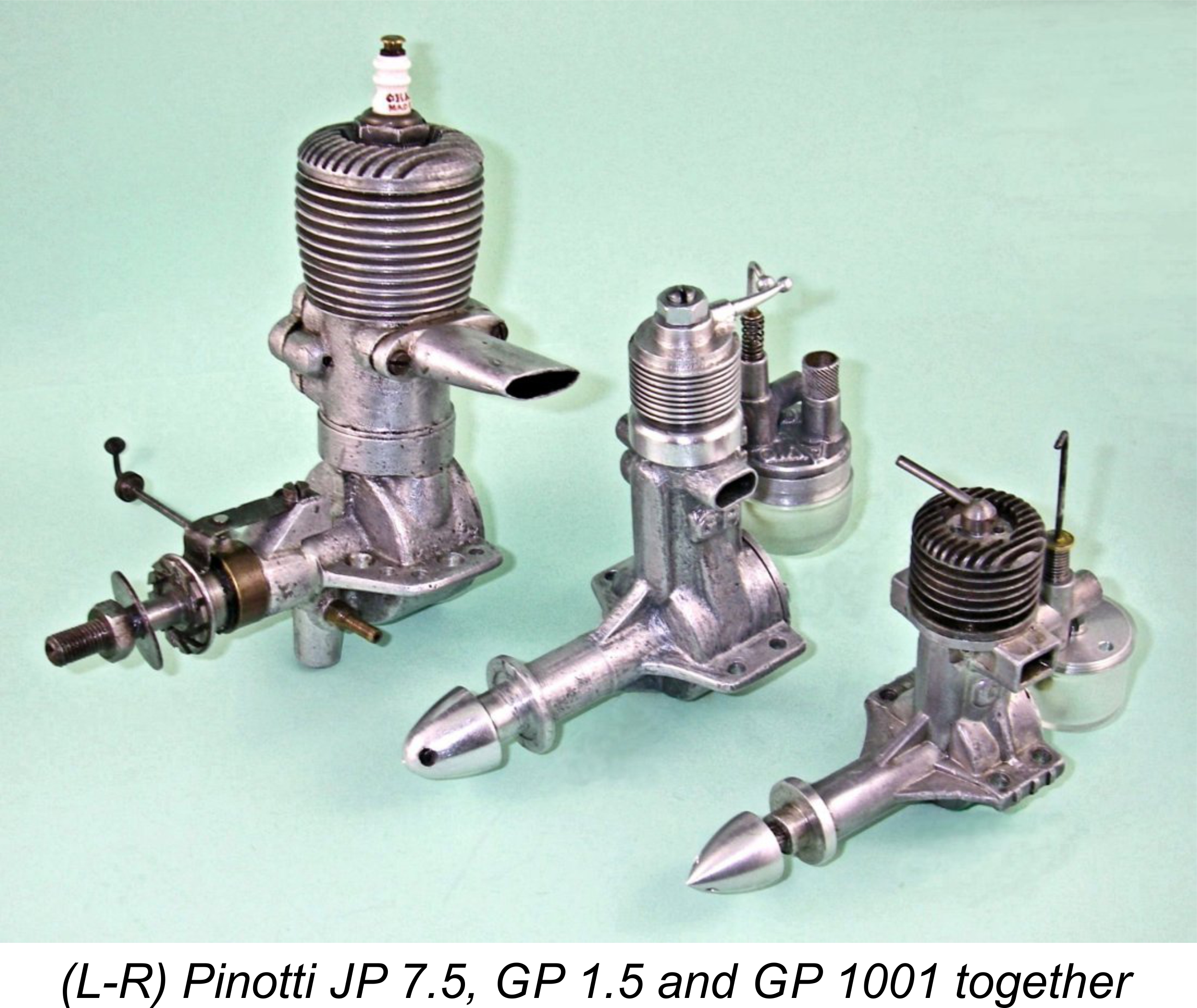
| |