
|
|
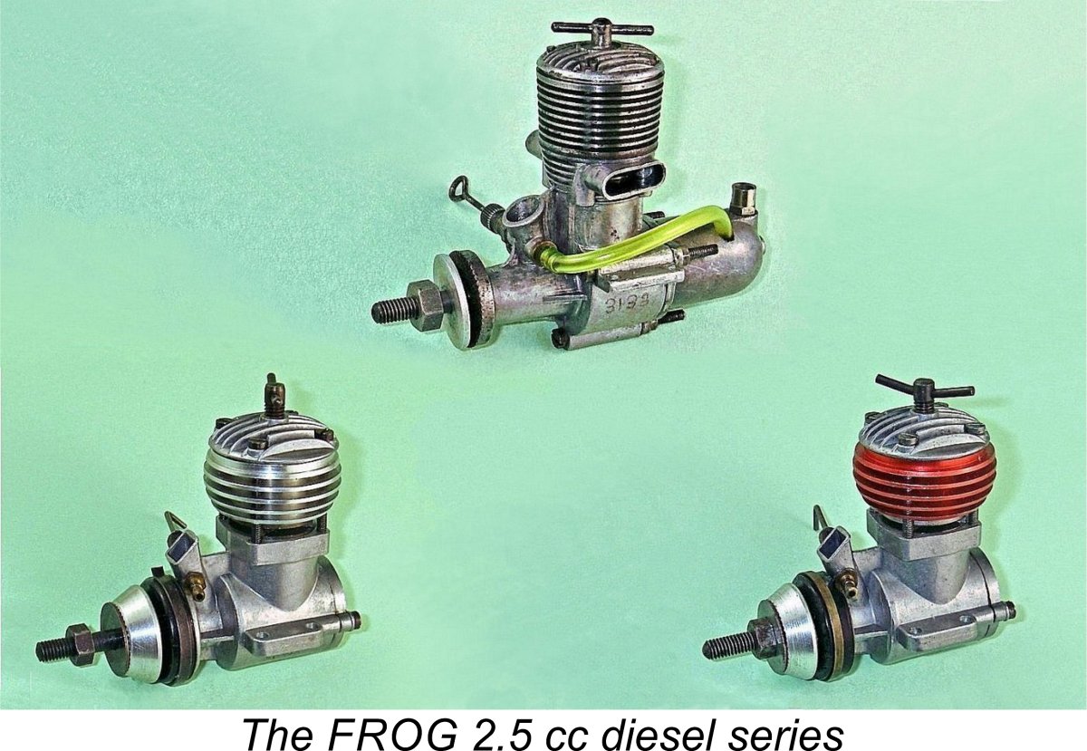
The 2.5 cc FROG Diesels
The one series of engines marketed under the FROG trade-name which has not been covered in detail previously is the relatively limited series of 2.5 cc models produced by the company. The present article will rectify this omission, thus completing my in-depth coverage of the entire FROG model engine range. I do not intend to repeat the material to be found in my other articles - here I’ll focus throughout on the 2.5 cc FROG models.
It’s probably worth mentioning at this point that the name of this range is correctly rendered as “FROG”, not “Frog” as often used. This is because it’s an acronym for the company’s motto “Flies Right Off Ground”. Both the manufacturer’s trade-mark and their advertising always used the upper case rendition, which also appeared on the engines themselves. A small point, but we may as well get it right! A FROG is a model aero engine or kit - a Frog is an amphibian! I’ve covered the early years of IMA’s involvement with model engine production in my article on the early FROG models. My article on the FROG 500 glow-plug/spark ignition model carried the story a little further into the early 1950’s. At that point, the company commenced its involvement with engines in the 1.5 cc category, as previously described in my detailed article on that series. The next displacement category with which IMA became involved was the 2.5 cc class. We’ll begin by looking at their motivation for doing so. Genesis of a New Model
For this reason, IMA never even considered introducing a 2.5 cc model during the first 4 years of their participation in the model engine market. Their largest diesel during this period was the FROG 180 of 1.77 cc displacement, while the late 1949 introduction of the FROG 500 leapt right past the 2.5 cc category, being aimed at the control line stunt and fledgling R/C markets from the outset. The earliest British moves towards raising the prominence of the 2.5 cc displacement category came in late 1947 from the model tether car racing community, which established a Class C competition category for engines of up to 2.5 cc displacement. In 1948 the Society of Model Aeronautical Engineers (S.M.A.E.) followed this lead by creating a Class II control line speed category for 2.5 cc powerplants. However, this displacement limit was not applied to other competition categories at this time.
The Class A category was generally viewed as a far less “glamorous” event than the 5 cc Class B alternative. However, it possessed the virtues of being both less intimidating to beginners and far more affordable. Accordingly, it soon became quite popular, also being taken up on the Continent. As of 1950 when the Class A category was established, there were only a few potentially suitable British engines which met the displacement criterion. These included the Mills 2.4, the E.D Mk. III and the Elfin 249, then in its die-cast beam mount plain bearing form. Using these powerplants, Class A team race speeds were typically in the range of 55-60 mph. How times change ……….. It’s clear that IMA took note of the increasing prominence of the 2.5 cc displacement category. In early 1950 they directed their resident engine designer, 1936 Wakefield Trophy winner Bert Judge, to proceed with the development of a diesel engine of that displacement. The result was the mid 1950 introduction of the first model in our main subject series - the FROG 250. The FROG 250 - Description
Beginning as usual with some relevant numbers, the FROG 250 featured near-square bore and stroke dimensions of 0.580 in. (14.73 mm) and 0.575 in. (14.60 mm) respectively for a displacement of 2.49 cc (0.1518 cuin.). These dimensions were to be retained throughout the FROG 2.5 cc series. Checked all-up weight of the 250 with tank and fuel tubing was 164 gm (5.78 ounces). At the time when the task of designing a 2.5 cc diesel was assigned to him, Bert Judge had just finished bringing the FROG 500 glow-plug motor into production. It should thus come as no surprise to see that the design of the FROG 250 showed unmistakable signs of having been influenced by that of the larger model.
The revised arrangement used in the 250 was doubtless adopted due to the impossibility of providing the piston crown with an upstanding baffle as featured in the 500, since such a baffle could not readily be accommodated by a conventional diesel contra-piston. This forced the designer to switch from cross-flow loop scavenging to reverse-flow scavenging. The arrangement which was adopted was clearly intended to maintain some directional control over the incoming mixture without the use of a baffle. The attached cutaway view extracted from the February 1951 "Model Aircraft" test (see below) should Obviously this arrangement precluded the use of the single bypass passage which had supplied the single large transfer port employed in the FROG 500. Instead, twin bypass passages of relatively small dimensions were provided at the front and rear of the upper crankcase between the exhaust stacks. These supplied mixture to four drilled transfer ports arranged in pairs at the front and rear of the lower cylinder between the exhaust ports. These ports were arranged in two pairs fore and aft and were drilled upwards at an acute angle to impart some direction to the incoming transfer gas. The longitudinally-finned cylinder head followed the FROG 500 pattern in being a separate casting which was secured by four long machine screws. These screws passed through holes drilled in the head and the cylinder fins to engage with tapped holes in the upper crankcase.
Many users of these engines found the long flexible needle valve to be more of a hindrance than a help in actual service. For that reason, many fliers switched to a far shorter straight needle. My own illustrated example is so equipped. It has also lost the cap to its Partridge fuelling cup, but is otherwise complete and original. One oddity with respect to the design of the FROG 250 was the fact that the crankshaft rotary induction valve closed at more or less exactly Top Dead Centre (TDC)! This is most unusual - generally speaking, the filling of the crankcase with fresh mixture will be incomplete at that point. More of this below in the latter-day test section of this article. Overall, the FROG 250 was very well made. At a selling price of £3 12s 6d (£3.63), it offered outstanding value for money. A workmanlike external appearance combined with excellent fits on all key components made this engine an attractive proposition for British power modellers of the early 1950’s. However, the proof of the pudding, etc………..many modellers held back initially on making a purchase to see what the resident engine testers of the day made of the new FROG offering. The FROG 250 on Test
Interestingly enough, Chinn commented that the FROG 250 was specifically not claimed by IMA to be “an ultra high-speed type, of phenomenal output”. Rather, the company claimed to have developed the engine primarily for radio controlled flying, a branch of the hobby which was then still very much in its infancy but was commanding increasing attention as time went by. The design objective had apparently been to achieve high levels of torque at modest rpm. Even so, Chinn stated that he had found the engine to possess “sufficient BHP over an adequate rpm range to extend its usefulness beyond R/C and similar free flight types to power duration machines and to control line models”. After commenting favourably on the engine’s construction and finish, Chinn went on to report that the FROG 250 started “very readily both hot and cold”. He was particularly complimentary regarding the engine’s ability to hold its speed under load with no tendency to sag as it became hot. He put this down to the use of integrally-formed cooling fins which eliminated the potential heat dam at the interface between the cylinder and a separate cooling jacket. Response to the controls was found to be very good, the one problem being that the previously-mentioned compression screw limiting disc did not permit the establishment of sufficient compression for smooth running above 9,000 rpm on un-nitrated fuel. This issue was addressed through the addition of 2% amyl nitrate to the fuel, after which no further difficulty was experienced. A peak output of 0.16 BHP @ 10,300 rpm was measured, with a quite respectable maximum Brake Mean Effective Pressure (BMEP) of 50 psi being recorded at 6,000 rpm.
Somewhat unusually, Sparey found a slightly higher performance than Chinn for this engine. In the majority of cases this situation was reversed - Chinn tended to find more power than Sparey, presumably as a result of different engine management and performance measuring techniques. In this case, Sparey reported a peak output of 0.192 BHP @ 10,700 rpm, a very good performance by the standards of the day. It was IMA’s misfortune that the appearance of these tests more or less coincided with the market debut of perhaps the most influential “consumer grade” 2.5 cc diesel of the early to mid 1950’s - the famous E.D. Mk. III 2.46 cc “Racer”. The introduction of this model in March 1951 immediately raised the 2.5 cc diesel performance bar, since the Racer was found on test to develop 0.260 BHP @ 14,100 rpm, putting the FROG 250 and its other consumer-grade competitors in the shade. It quickly became the engine to beat in the Class A team race category until the arrival of the Oliver Tiger Mk, III, also achieving great success in other categories such as control line stunt and free flight duration. Still, the FROG 250 was a well-made, user-friendly and competitively-priced unit which performed at a perfectly adequate level to meet the needs of the sport fliers who then (as always) greatly outnumbered their serious competition-minded colleagues. Although not apparently a massive seller, it did receive sufficient sales attention to justify its place in IMA’s ongoing model engine production program. It was still appearing in IMA advertisements in mid 1955. I have no authoritative information regarding production figures for this engine. My Scots friend Don Imrie owns engine number 2584, while my own illustrated example bears the serial number 3133. Maris Dislers reports owning engine no. 4003, while engine no. 4283 resides with Helmut Lichtenberg in Munich, Germany. However, there’s little doubt that total production exceeded this number by a significant amount. If you have any serial numbers available, please share them! The FROG 250 - a Latter-Day Test
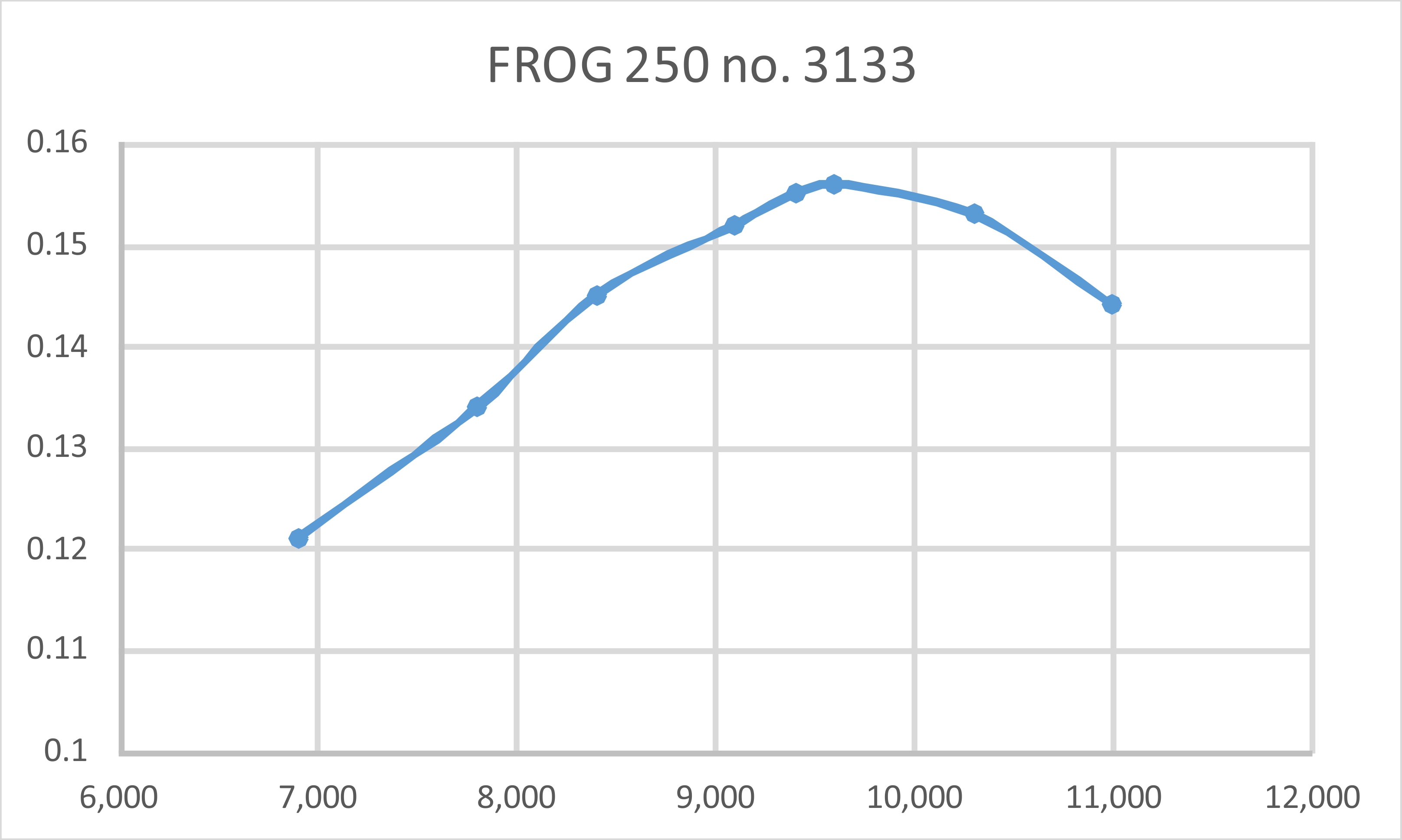
This example has seen a fair bit of use, but has clearly been well cared for during its service life. Consequently, it remains in first-class mechanical and cosmetic condition apart from the missing cap for the Partridge fuel filler cup. It required no running-in, merely a few preliminary shake-down runs. I elected to use the engine's back tank for this test, stopping the engine between prop changes by pinching off the fuel line. Having reviewed Peter Chinn's test of teh engine, I chose to begin with a 10x6 APC airscrew. The FROG 250 endeared itself to me immediately by showing itself to be an extremely easy starter. The manufacturer's recommendation of a small exhaust prime Once running, things continued to go very well indeed. Response to both controls was excellent, making the establishment of optimal settings very straightforward. Once set, the engine ran perfectly, with no trace of a misfire and no tendency to sag. Both controls held their settings securely while remaining fully adjustable at all times. I did not experience Chinn's problem of an inability to reach an adequate maximum compression setting for high-speed running - my example still had about a quarter turn in hand before the limiting disc prevented any further increase. The results that I obtained with the various calibrated airscrews employed more or less precisely duplicated the results reported by Peter Chinn. The following data were obtained on test.
The implied peak output of around 0.157 BHP @ 9,900 rpm is very much in line with the figures of 0.160 BHP @ 10,300 rpm reported by Peter Chinn way back in February 1951. I would say that my latter-day test confirmed Chinn's findings in every respect. The engine took all of this test running in stride, exhibiting no signs of mechanical distress and remaining in perfect condition, all ready for as much work as might be sent its way. Overall, I would rate this as a well-made and extremely user-friendly model powerplant that would have offered excellent value for money. However, it could have been even better! I previously mentioned the rather odd fact that the induction system of the FROG 250 as delivered closed more or less exactly at TDC. My mate Maris Dislers had a rather well-worn example of the engine which he used to evaulate the impact of this seemingly-inappropriate feature upon performance. Maris reconfigured the crankshaft's induction port to have it close at 25° ATDC - a very obvious modification. With the exhaust and transfer periods set at 130° and 110° respectively, the modified engine generated a peak output of around 0.220 BHP @ 11,000 RPM - a very significant improvement in terms of both figures! I've often had cause to wonder at the frequency with which the early British designers (and some from elsewhere) missed simple and very obvious alterations to their designs which would have improved performance significantly without affecting production costs much if at all. Maris's previous efforts relating to the E.D. Cadet were a case in point, as were my own efforts with the E.D. 2.49 Mk. III, the E.D. Bee Mk. I Series 2, the J.B. Atom and the FROG 349. All of these engines have responded very well indeed to a few simple performance-enhancing modifications which could easily have been incorporated in the production models at little or no extra manufacturing cost. It appears that the development budget didn’t allow for much in the way of experiment and field testing. Also, it seems clear that the dynamics of gas flow in small two-stroke engines were imperfectly understood at the time in question. Upgrade - the FROG 249 BB As noted earlier, the FROG 250 was clearly a steady if unspectacular seller for a number of years. However, the FAI’s adoption of the 2.5 cc displacement limit for the 1955 International contest season and beyond raised the profile of that displacement category considerably. At the same time, the performance shortfall of the FROG 250 by comparison with other competing models had reached the point at which it was clear that IMA would have to develop an upgraded 2.5 cc model if they wished to continue to participate in the 2.5 cc marketplace.
Returning our attention to IMA, after a hiatus during which no further model engine development took place, Judge’s position as IMA’s chief engine designer was finally taken by George Fletcher, who came from a model engineering family – his father had won awards at Model Engineer exhibitions. Prior to joining IMA, Fletcher had worked in the commercial model engine manufacturing industry for both D-C Ltd. and Allbon Engineering, hence having considerable experience in the fields of model engine design and commercial production. In early 1955 Fletcher was tasked by IMA management with the job of developing a 2.5 cc model which would be competitive in that rapidly-evolving displacement category. This would be the first new design for which Fletcher was totally responsible - previously, he had worked on design and production improvements to existing models originally designed by Bert Judge, such as the 0.5 cc FROG 50.
The new model was a very up-to-date twin ball-race FRV model having well-developed radial cylinder porting with reverse flow scavenging. Bore and stroke of the new design were unchanged from those of the preceding 250 model at 0.580 in. (14.73 mm) and 0.575 in. (14.60 mm) respectively for a displacement of 2.49 cc (0.1518 cuin.). Weight was also virtually unchanged at 165 gm (5.8 ounces), although this figure naturally didn’t include a tank plus fuel tubing. Starting at the top, the new model once again sported a cast longitudinally-finned cylinder head. However, the compression limiting disc was omitted from the compression screw. Instead of the integrally-formed cylinder cooling fins, the 249 BB featured a separate alloy cooling jacket. The head, jacket and cylinder were all secured to the crankcase with four long machine screws.
The cylinder port timing of this design was rather odd. The exhaust ports opened very early indeed at only 97 degrees after top dead centre (ATDC). This resulted in an exhaust period of no less than 166 degrees as opposed to the far more usual figure of somewhere in the vicinity of 135 - 140 degrees. Since it shortened the period of the effective power stroke to only 97 degrees, such an early opening would logically be expected to result in lower torque development than might otherwise be the case. So what was the motivation for this unusual design parameter? One potential explanation would be the need to provide for an adequate transfer period following blow-down. However, this doesn’t apply in this instance - the transfer ports There are several downsides attached to the use of such an early opening of the transfer ports. First, it greatly limits the period of rotation during which mixture is being compressed in the crankcase prior to being driven up through the transfer ports into the cylinder. That crankcase compression cannot begin until the induction system has closed, and it ends when the transfer ports open to relieve the pressure. The FROG 249 BB had a crankcase compression period of only 63 degrees. Consequently, the pressure in the case at the point of transfer port opening would be somewhat lower than ideal. This would have an adverse effect upon initial transfer gas velocities in the cylinder. Secondly, an extended transfer period also constrains the point at which effective induction can begin. Regardless of where the rotary valve opens, it should be clear that the rising piston’s creation of negative pressure in the crankcase to draw in fresh mixture can’t commence until the transfer ports are closed, thus sealing the crankcase from the still-open exhaust ports. This pretty much constrained the FROG 249 BB’s design to the very late induction port opening which was actually provided. Once again, this in turn limited the volume increase in the crankcase which could actually be used to draw in fresh mixture. In turn, this limited the actual volume of fresh mixture which could be drawn in during each induction cycle. Finally, with an efficient transfer system like the Oliver arrangement, such a lengthy transfer period was completely unnecessary! Ideally, the transfer ports should remain open only long enough to allow the pressure in the crankcase to be completely relieved down to atmospheric level by the discharge of mixture through the transfer ports into the cylinder. With a free-breathing transfer system such as this one, that point will be reached relatively soon after bottom dead centre, after which the rising piston will take up any residual crankcase pressure. All that the still-open transfer ports accomplish after that point is to delay the effective commencement of the induction phase. Based upon the above arguments, I’d be prepared to bet that the engine would have performed measurably better with both exhaust and transfer periods reduced by at least some 16 degrees apiece for revised figures of 150 degrees and 130 degrees respectively. I’m at a complete loss to explain the use of such seemingly excessive exhaust and transfer periods in this design.
The piston and contra-piston were both machined from Brico cast iron. The short-skirted piston had a conical crown, with the underside of the contra piston being formed to match. The conrod was a high-quality light alloy forging. The one piece steel crankshaft had a counterbalanced crankdisc and a main journal diameter of 0.375 in. It was supported in a pair of high-quality ball-races. Unusually, both of these bearings were the same size, requiring a far larger than normal front bearing housing. The front bearing was protected against dust and dirt entry by a synthetic rubber cap which was retained in position by a flat-section circlip. It's actually an automotive brake cylinder seal. It is very common indeed to find that this seal has become damaged or otherwise deteriorated over time for a given example of the FROG 249. Reader David Brown of Australia was kind enough to advise that, having just such a deteriorated seal on his example of the engine, he found that a perfect replacement was an automotive brake cylinder seal for a Morris Minor, Morris 8 or MG TC (from a 7/8" (BA1) kit). He was able to purchase such a seal from British Classic Spare Parts on eBay. Owners of these engines with deteriorated sealsm please take note! My thanks to David for sharing this very useful information. The induction port in the crankshaft was a simple round hole. In combination with the round intake register in the crankcase, this gave relatively slow opening and closing, with a comparatively short “fully open” period - not the most efficient arrangement. The timing also seems to be a little odd - the induction port opened very late at 75 degrees after bottom dead centre and closed equally late at 44 degrees after top dead centre. To me, both of these figures appear somewhat late for best results, especially given the fact that the induction process was supplemented by a generous 45 degree period of sub-piston induction (22½ degrees either side of top dead centre). The actual induction period provided was 149 degrees - a relatively conservative figure for a supposedly high-performance engine. However, the very early opening and consequent late closure of the transfer ports set a practical upper limit on this parameter for the reasons noted earlier.
The visible square section of the intake venturi's entry was misleading, since it was smoothly recontoured internally into a circular configuration by the time that the spraybar location was reached. At that point it had a rather skinny throat diameter of 0.221 in. (5.61 mm), while the spraybar diameter was a healthy 0.140 in. (3.56 mm). Reference to Maris Dislers' invaluable Intake Choke Area Calculator shows that this combination results in an effective throat area of 6.183 mm2 with a minimum operating speed for a 2.49 cc engine running on suction of 8,939 rpm when used in a sport or combat application. It's clear that a somewhat greater effective choke area could have been tolerated, even with the sub-piston induction. Such a change would probably yield a measureable improvement in peak performance. At the rear, the backplate was secured to the crankcase by two machine screws which registered with tapped holes in the rear of the engine's mounting lugs. A fibre gasket was used to ensure a seal. The backplate’s installation spigot was very long, extending almost right to the rear of the crankpin at full crankcase diameter. This minimized crankcase volume - a good thing - but also had the negative effect of greatly constricting direct gas access to the rear portion of the annular passage which served as the bypass. Overall, the FROG 249 BB came across as something akin to a “poor man’s Oliver”. It shared the same basic porting arrangements, although the bypass arrangements were nowhere near as well developed as those of the Oliver, while the timing unquestionably left something to be desired. Nevertheless, the engine handled superbly and performed at a level which was more than satisfactory as far as the majority of British power modellers were concerned. Moreover, at a price of £3 19s 3d (£3.96) it offered excellent value for money. It was an immediate sales success - I saw many examples in use during my early modelling years. An issue about which I’ve heard but which I’ve never experienced myself is that of fatigue failure of the crankcase, which is undeniably provided with rather thin walls. I’ve been reliably informed that a number of these engines have been known to crack at the front of the crankcase for no other reason than long-term exposure to operational vibration. Having been a FROG 249 BB user myself for many years, I can only say that I have yet to experience such a failure. Nonetheless, I feel obliged to report it as a possibility of which users should be made aware. The FROG 249 BB on Test
Taking Peter Chinn’s test first, Chinn began by commenting on the engine’s refreshingly unusual overall appearance. He drew favourable attention to the forward location of the beam mounting lugs, also praising the use of the synthetic rubber seal to protect the front ball race. He commented non-judgmentally upon the engine’s unusually long exhaust period. In operational terms, Chinn characterised the FROG 249 BB as “quite the most well-mannered diesel that we have encountered for a long time”. He stated that starting was “exceptional”. He found the engine to be remarkably docile even with small-diameter propellers, having no tendency towards viciousness. This latter characteristic was very likely due to the engine's unusually short effective power stroke. Control response was said to be “entirely satisfactory”. Running was evidently very good at all speeds tested, although Chinn did find that the FROG liked a fairly heavily nitrated fuel for high-speed running. In my personal opinion, this too was probably due to the long exhaust period with its attendant relatively short effective compression period. Chinn reported a peak output of 0.256 BHP @ 14,700 rpm. This was a very good figure indeed for a mass-produced competitively-priced “consumer grade” 2.5 cc diesel in 1956, coming very close to matching the 0.265 BHP @ 13,800 rpm later reported by Chinn in December 1957 for the “mass production” bench-mark E.D. Racer. Only the high-priced individually-produced “specials” like the Oliver Tiger Mk. III and (later) the 1957 P.A.W. 249D “Special” could beat the FROG at the time of its introduction and for some time thereafter.
Ron Warring’s test published in the January 1956 issue of “Aeromodeller” was equally complimentary. Warring cited the engine’s starting qualities as being “excellent”, with very good control response. He also noted the engine’s lack of viciousness, even on small airscrews. In performance terms, Warring was unable to match Peter Chinn’s figures. As mentioned earlier, this was not unusual at the time - Chinn routinely tended to report higher levels of performance than Warring, presumably for reasons relating to engine management and performance measurement techniques. Whatever the reason, Warring reported a rather lacklustre peak output of only 0.206 BHP @ 13,700 rpm. Both of these figures are substantially below those reported by Chinn. I can only report that long experience of this design in the field tends to support Chinn’s figures rather than those reported by Warring. Warring concluded his report by more or less reiterating Chinn’s assessment that the FROG 249 BB combined “pleasant starting and handling characteristics” with sufficient performance potential to “hold its own against them all”. The last statement was perhaps a bit of an exaggeration based on Warring’s own figures, but the underlying message was nonetheless unmistakably positive. A Step Sideways - the FROG 249 BB "Modified" International Model Aircraft (IMA) was one of the British firms which made quite serious efforts to establish a marketing bridgehead in the USA. It must be appreciated that while the proportion of American modellers who used diesels was quite small, the sheer size of the US market was such that by British standards America remained a worthwhile market area. By 1956 IMA had been successful in arranging for World Engines of Cincinnati, Ohio to act as their American distributors. The FROG 249 BB was one of the models which appeared to have the greatest sales potential in the USA. However, after evaluating the original version of this engine just described, World Engines decided that a higher level of performance was required in order to render it competitive in the American market. This prompted them to go back to IMA in early 1956 with a request that they develop a modified version of the engine to raise speeds on props in the 11,000 - 13,000 rpm range by around 1000 rpm. It was felt that this would significantly improve the engine’s sales potential in the USA.
Chinn found that the modifications had resulted in at least a 10% improvement in power output. On the basis of his comments to the manufacturers, a few batches of “Modified” engines were produced in mid 1956 and sent to World Engines. However, the examples of the 249 BB being offered on the home and Commonwealth markets continued to be the original standard model. Lacklustre sales in America soon led IMA to the conclusion that the marketing of the revised model could best be expanded by opening its distribution up to the home and world markets. Learning of this plan, Peter Chinn felt able to describe the FROG 249 BB "Modified", as it came to be known, in the June 1957 issue of “Model Aircraft”. The modified engine was finally released to home and world markets in July 1957. At a price of £4 14s 9d (£4.74), it was some 15 shillings (£0.75) more expensive than the earlier version, which continued in production to meet the needs of modellers on a tighter budget.
Both the style of porting and the port timing were altered considerably to create the new model. To begin with, the modified engine featured both exhaust and transfer ports which were sawn slots - the former drilled “Oliver style” transfers were abandoned. At first sight, this has the appearance of being a retrograde step, which it almost certainly would have been had the exhaust timing been left unaltered.
To some extent this was compensated for by the fact that although they were open for a greatly reduced period, the sawn transfer ports had a far greater combined area. Moreover, the extended crankcase compression period provided by the far later transfer port opening would give rise to significantly higher crankcase pressures to initiate the transfer process. The outer wall of the lower cylinder was also contoured to ease the passage of gas from the crankcase to the transfer ports. The induction period provided by the crankshaft rotary valve remained unchanged despite the fact that the system's opening and closure could easily have been advanced by, say, 14 degrees to initiate the induction process far earlier. Presumably the decision to stick with the original timing was a cost-related decision, since the same shaft could be used for both models with no changes to the related tooling. The downward relocation of the exhaust ports extended the sub-piston induction period from 45 degrees to 54 degrees. Even so, the rotary valve induction system still remained open well after the closure of the sub-piston induction phase. This further underscores the earlier observation that both opening and closure of the rotary valve could almost certainly have been made earlier with advantage. Despite the seeming step backwards in technical terms which these cylinder porting changes embodied, one couldn’t argue with the immediate results. Both Peter Chinn and Ron Warring published tests of the “Modified” engine which confirmed the improvement in performance. Warring’s report appeared in the February 1958 issue of “Aeromodeller”. After stating that “all the good starting and running characteristics of the standard 249 BB have been retained - if not enhanced”, Warring reported a peak output of 0.253 BHP @ 14,800 rpm - a considerable advance over his original figures for the standard model.
Now we get to the controversial bit! I will confess to having been very impressed with George Fletcher’s low-cost application of the well-proven Oliver cylinder porting system to the original FROG 249 BB. This looked to me like a classic case of borrowing from the best! Consequently, I was more than a little surprised to learn that the supposedly improved “Modified” version retreated from the Oliver design to the old standby sawn port system first used way back in 1951 by E.D. with their famous 246 Racer. To me, a far more logical approach would have been to further develop the original Oliver porting concept. Putting my money where my mouth was, I proceeded years later (after I acquired the necessary tools and skills) to modify an example of the original model to see if I could beat the reported performances of the “Modified” version. I was frankly pretty confident that I could do so. Let’s see what I did and how it worked out! A Tweaked Oliver-Ported FROG 249 BB
Firstly, I noted that the piston could be substantially lightened by appropriate turning and milling. The reduction of an engine’s potential to generate vibration is always a very positive performance enhancement - energy being used to shake the motor and the airframe isn’t available to turn the prop. A reduction in reciprocating weight is the most direct means of minimizing power losses from this cause. I took as much material as I deemed safe out of the piston, lightening it considerably to just under 5 gm while maintaining adequate gudgeon pin bosses. That’s pretty light for a lapped cast iron piston in a 2.5 cc diesel! The crankweb was already nicely counterbalanced, so I reckoned that vibration levels should now be well under control. Indeed, subsequent operational experience with this engine amply confirmed that expectation. Next up was the induction system. I removed the shaft and elongated the induction port in a fore and aft direction without widening it at all. I would have liked to have it open somewhat earlier, but I felt that this would require taking too big a bite out of the shaft for adequate strength, while the value of such a modification would be significantly reduced in any case because of the very late transfer port closure on the compression/induction stroke.
To assist in the escape of gas from the crankshaft’s induction passage, particularly around bottom dead centre when the case is theoretically still under some residual pressure, I created two small channels in the rear face of the crankdisc on the I mentioned earlier that the transfer ports were perhaps a touch undersized. I enlarged them a little, also widening and lengthening the channels in the outer lower cylinder wall which directed mixture towards the ports. Finally, I streamlined the lower outer edge of the cylinder wall to ease gas flow into the annular bypass passage.
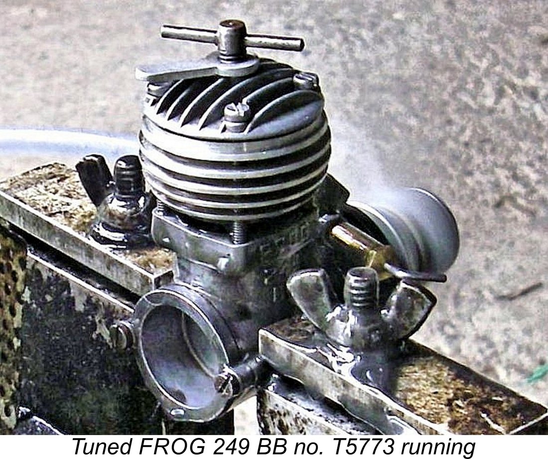
I would have liked to reduce both exhaust and transfer periods significantly by lowering the cylinder, but the presence of an already-substantial period of sub-piston induction discouraged this - even a small lowering of the cylinder would increase this figure significantly. I ended up contenting myself with discarding the fibre cylinder base gasket and lapping the cylinder’s location flange into its seat in the crankcase to retain a gas-tight seal. This lowered the cylinder by a measured 16 thou, reducing both exhaust and transfer periods by a few Having hopefully got a little more fuel mixture into the combustion chamber during each cycle, I naturally wanted it to burn as efficiently as possible. To that end, I added a suitably-dimensioned squish bowl to the contra piston. Since this component is made of hardened steel, I had to accomplish this by grinding. As a final step, I replaced the standard FROG needle valve assembly with P.A.W. components. I’ve always found the P.A.W. needle valve to hold its settings better than any other system apart from that used by Super Tigre. In addition, replacements are readily available. Bearing in mind my earlier appraisal of the FROG's carburettor dimensions, I waisted the working length of the spraybar down from a diameter of 0.140 in. (3.56 mm) to 0.120 in. (3.05 mm). Maris Dislers' Intake Choke Area Calculator showed that this modification raised the minimum operating speed on suction for sport and combat applications to 12,278 rpm. Since I expected the modifed unit to operate in the air at a considerably higher speed than this, I reckoned that these dimensions would be OK. After giving the modified FROG a few break-in runs to settle it down after its rebuild, I installed it in a “Chaos” combat wing. It proved to be both an excellent starter and an outstanding performer in the air, pulling the fairly large model around with great authority while running very smoothly and consistently. I used it for a few years in that model before temporarily setting it aside for a rest. When planning to write this article, I dug out the trusty old tuned FROG to take the above photos and put it through a bench test. It was very well settled down by this time, having a good few hours of air time under its belt. It started extremely easily and ran superbly on all props tested. Following a few shakedown runs to settle it down after being dismantled for the photographs, it delivered a spirited performance which greatly exceeded the figures reported by both Chinn and Warring for the FROG 249 BB “Modified”. The following data tell the story.
The above data imply a peak output of around 0.318 BHP @ 14,500 rpm. This is right up with the very best 2.5 cc competition diesels of the mid 1950’s, including the Oliver. It’s interesting to note that the peaking speed was unchanged - my modified engine clearly developed more torque across the board but followed As far as I’m concerned, this test has pretty much confirmed my long-held suspicion that the original Oliver-ported version of the FROG 249 BB had far greater development potential than the “Modified” variant. It’s important to note that most of my modifications could easily have been incorporated into the standard production engine at minimal additional cost. I would have considered a modest additional cost to be well justified by the engine’s considerably enhanced performance. If it had been released with a more rational timing diagram, I have no doubt that the original over-the-counter FROG 249 BB would have performed at a significantly higher level than it did. The puzzle of how George Fletcher came up with the port timing figures that he ended up using will always remain a mystery! Change of Manufacturer
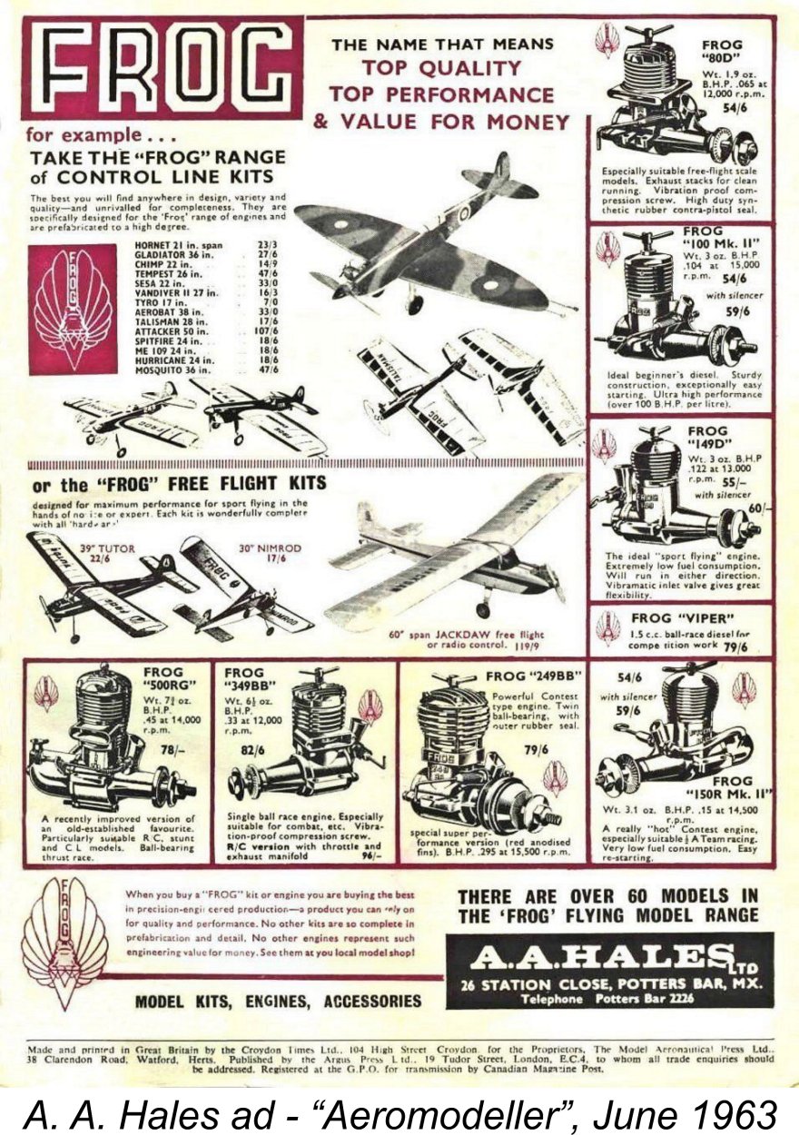
A major distibutor of the FROG model engines had been the A. A. Hales organization of Potters Bar in Hertfordshire, just north of London. In the latter part of 1962, Lines Brothers purchased a majority shareholding in the A. A. Hales company, a move which was announced in the "Trade Notes" feature in the February 1963 issue of "Aeromodeller". At the time of this transaction, there were significant numbers of completed engines already in existence. A. A. Hales was charged with the responsibility for the future marketing of the various FROG products. After 1962, no more was to be heard of IMA in connection with the FROG model engine range. IMA continued to produce their FROG plastic kit range in great volume but had no further involvement with flying models. IMA actually ceased advertising in "Aeromodeller" after June 1966, undoubtedly because that magazine catered primarily to flying modellers. Hales already produced their own range of model kits under the "Yeoman" label (who remembers the "Dixielander", the "Bantam Cock" and the "Scorcher"?). Despite apparently being in competition with themselves, Hales continued to market not only the FROG engines but also many of the established FROG flying model kits. These latter were almost certainly existing stocks acquired at the time of Hales' purchase of the FROG marque from Lines Brothers. As remaining stocks of FROG engines ran down during this period, the Hales organization must have detected some level of continuing demand for the FROG model engine range which would not be satisfied merely by selling off existing IMA-produced units. In 1964 they made arrangements with the parent Lines Brothers company to acquire outright ownership of the FROG model engine range. This transaction involved the transfer of all of the FROG engine dies and tooling to Davies-Charlton Ltd. (D-C Ltd.) on the Isle of Man. Thereafter, the manufacture of many of the FROG engines resumed, now being undertaken by D-C Ltd. under contract to A. A. Hales, who were still a Lines Brothers subsidiary at this time. The serial number sequence was restarted with a code letter preceding the digits, thus making it easy to distinguish between IMA and D-C-made engines. This was a very sensible idea, as IMA had simply numbered the engines in each displacement category sequentially from 1, consequently generating complete sets of duplicate serial numbers! The approach taken by A. A. Hales eliminated the duplicates and made each number unique. The following table shows the system used:
† Probably assembled by D-C Ltd. from residual IMA parts, not manufactured by them.
Both the Oliver-ported and "Modified" versions of the FROG 249 BB appear to have been manufactured by D-C Ltd. - I have examples of both variants bearing T prefixes. The "modified" version retained the red-anodized cooling jacket of its IMA predecessor, although the cylinder head was a revised component having a far greater thickness. This resulted in the engine becoming a little "taller" than before. This variant appears to have been the "last man standing" - the serial number of my illustrated example is the highest T-prefix number that has yet been reported, while the wording of the final advertisement seen below at the left appears to imply that the model being advertised is a "Modified" example.
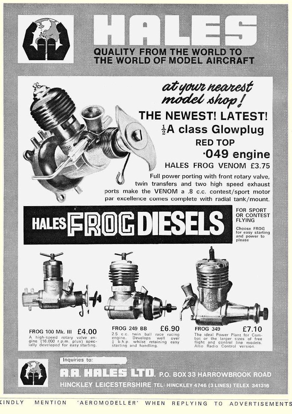
Gordon Beeby of Melbourne, Australia, was kind enough to undertake a thorough review of the Hales advertisements which appeared in "Aeromodeller". The FROG range as manufactured by D-C Ltd. continued to be advertised periodically throughout the 1960's. The accompanying advertisement from April 1966 is typical - the same models were featured throughout. All these engines remained on offer through to August 1971, when the incipient arrival of an .049 glow-plug unit called the FROG Venom was announced by Hales. The Venom duly appeared in September 1971, but proved to be just a red-head radial mount version of the glow-plug D-C Wasp, hence being a simple case of badge engineering - a D-C Wasp with the FROG name substituted. It is not to be confused with the earlier 1.5 cc FROG Venom glow-plug unit, nor is it a "genuine" FROG design. As far as Gordon could determine, the final consumer market advertisement for the A. A. Hales/D-C Ltd. FROG engines appeared in the September 1972 issue of "Aeromodeller" magazine. That final September 1972 engine ad (which is reproduced below at the left) included the FROG 249 BB, so it seems to have survived to the very end of the advertised mainstream FROG engine range after a marketplace presence of some 16 years. Both the FROG 150 Mk. III and the FROG 80 Mk. III had been dropped by this time.
One of the remaining questions is whether Hales/D-C Ltd. continued the serial number sequence started by IMA, or whether they restarted the sequence using the letter prefix to differentiate between the older and new models. There is strong evidence to suggest that they restarted the sequence. For one thing, Kevin Richards is aware of an IMA FROG 150R bearing the number 28031 and a later D-C-made FROG 150 Mk III with the lower number of F19920. Of course, it's possible that the 150 Mk III was seen as a different engine, justifying a sequence restart, but the FROG 349 numbers also support the global restart hypothesis. The highest 349 serial number known to me without the Z prefix is 13225, while the lowest numbered Z-prefix example of that engine of which I'm currently aware is engine number Z83 owned by Chris Ottewell. This is pretty hard evidence that the count for that model was restarted at Z1 when D-C Ltd. took over the manufacturing. It’s logical to assume that all models were re-numbered in this way. The one remaining question is whether they started again at (prefix)1 or at some intermediate figure. At present I'm unable to answer this question definitively, although the number of Chris Ottewell's engine strongly suggests that they started at (prefix)1. How many examples of the FROG 249 were made? Like all FROG engines produced by IMA, the original 249 was numbered sequentially starting from 1, the serial number being hand-engraved onto the lower crankcase rather than being stamped. The lowest FROG 249 BB serial number so far reported is my own engine number 418, while the highest such number of my present acquaintance is 5644. They probably went considerably higher than this. My own example of the FROG 249 BB 'Modified" bears no serial number. This is odd, because it's New-in-Box and was obtained from its original owner, a good friend of mine, who bought it new in 1958 but never ran it. The only numbers of which I'm currently aware are Don Imrie's engine no. 2299 and Maris Dislers' unit no. 2389. If IMA followed their usual practise with this model, they would have started a separate sequence for it at engine no. 1. We thus appear to have evidence for the production by IMA of at least 2400 examples of this model. Doubtless there may well have been more .......... As far as the T-prefixed examples made by D-C Ltd. go, I currently have confirmation of only two numbers - my own tuned Oliver-ported T5773 and previously-illustrated "modified" engine number T8127. Hence I have not yet established an intersection which would confirm that the serial numbers were re-started by D-C Ltd. at T1 - I can only say that it seems highly likely that they did so based on their treatment of other series. Taking all of the above figures into consideration, it seems that we have evidence for the production by IMA of at least 5,700 examples of the original Oliver-ported variant and 2,300 examples of the "Modified" version. It's highly likely that there were considerably more than this. D-C Ltd. appear to have added at least an additional 8,200 examples of both types together. We probably wouldn't be far wrong to suggest that at least 18,000 examples of both types in total may have been manufactured. My good mate Kevin Richards was able to confirm that new examples undoubtedly remained available through dealers until at least 1970. Kevin bought new unrun boxed examples of both the 249 BB and the 349 BB from his local hobby shop in that year. He still had that 249 BB new in the box complete with 1970 dealer-stamped factory guarantee! Of course, a dated dealer stamp merely confirms the date of sale - it does not represent evidence of continued manufacture at that date. Accordingly, this cannot be taken as evidence of continuing manufacture as of 1970 - it’s highly likely that they were simply selling off New Old Stock by that time. But it does confirm that new examples of the engine remained available from dealers for a considerably longer period than I had originally supposed. The final chapter in the FROG saga came in 1972, when Alan Hales bought back the A. A. Hales brand from the Lines Brothers liqidators, presumably at a fire-sale price. A few advertisements for the FROG engines were placed thereafter (February and September 1972), but these almost certainly represented nothing more than an attempt to sell off some remaining New Old Stock. The September 1972 advertisement marked the final promotional appearance of the FROG engines. The Aurora Indian Connection
At some point following the cessation of manufacture of the FROG engines in Britain, the dies and perhaps some of the tooling appear to have been acquired by Aurora. By 1972 they were producing their own versions of several FROG models, including of all things the old 149 Vibramatic model which was featured in Peter Chinn's "Latest Engine News" column in the November 1972 issue of "Aeromodeller". In addition, Aurora introduced two ball-race models designated the K250 BB and K350 BB. Although they used screw-in cylinders and backplates as well as plug-in venturi inserts, these engines were quite recognizably based upon the old Oliver-ported FROG 249 BB, which had been one of the more popular British engines in India. They were very successful, continuing in production for many years with a few changes along the way. I have personally used a self-modified example of the "middle" variant of the 2.5 cc version with great success. Conclusion
I’ve demonstrated (to my own satisfaction at least) that the original Oliver-ported version of the engine had the potential to be at the very top of the performance heap during the mid 1950’s. The request from World Engines that a higher-performance version be developed could readily have been addressed through suitable modifications to the Oliver-ported unit - there was ample potential. The approach actually taken represented a step backwards in technological terms by reverting to a far more confining porting arrangement that, while offering an immediate performance improvement over the standard model, nevertheless painted IMA into a developmental corner. As released, that model was about as tweaked as it could be - the potential for further improvement was extremely constrained by the inherent limitations of the porting system adopted. By contrast, the Oliver-ported variant had ample potential for further development as the need dictated. I suspect that the underlying cause of this situation was IMA management’s demand for an immediate response by George Fletcher to World Engines’ request for performance enhancement. I see the FROG 249 BB “Modified” as a short-term band-aid response to that request. If Fletcher had been granted the necessary time and budget, I consider it to be highly likely that he would have continued the development of the Oliver-ported version - I’ve shown that the potential was undoubtedly there. The response that he did come up with was the best that he could do within the compressed time-frame and tight budget limitations under which he was required to work. Still, the final version of the engine upheld the well-established FROG tradition of offering a quality product having a perfectly adequate performance for most purposes, and at a very reasonable price. Indeed, all three FROG 2.5 cc models merit our respect for achieving that very worthy goal! __________________________ Article © Adrian C. Duncan, Coquitlam, British Columbia, Canada First published August 2021 |
||
 In other articles both on this website and elsewhere, I’ve traced the history of the well-known model engine range manufactured by Lines Brothers subsidiary International Model Aircraft (IMA) Ltd. under the FROG banner between 1946 and 1962. I’ve written separate articles on the
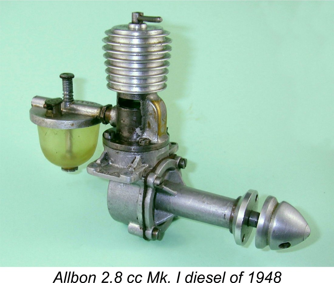 During the latter part of the 1940’s, there was nothing particularly special about the 2.5 cc model engine displacement category. The FAI’s adoption of the 2.5 cc displacement limit for International competition (excluding R/C and control line stunt) was still years in the future. Meanwhile, engines having all kinds of what we would consider to be oddball displacements remained in widespread use - the illustrated
 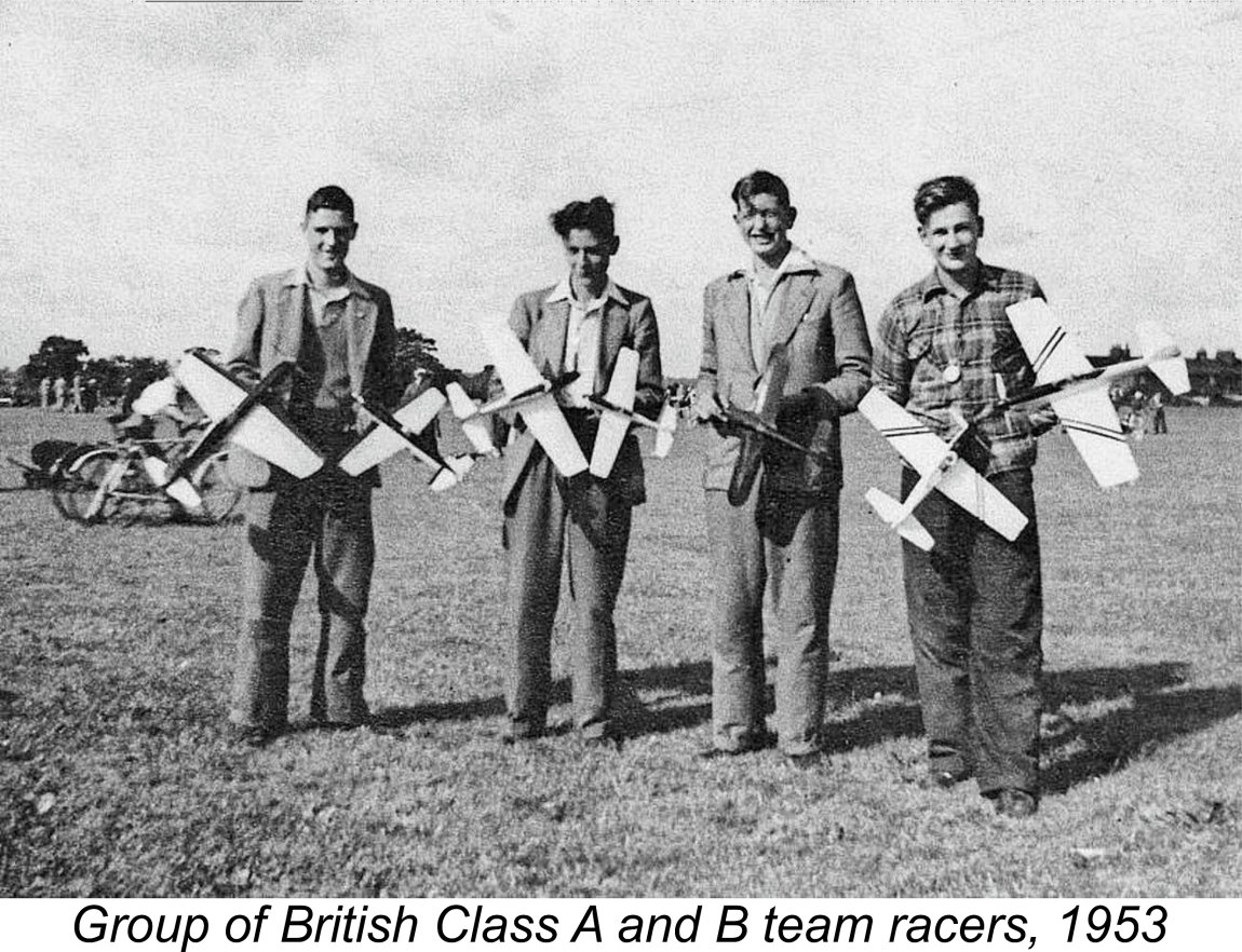 The innovation which really began the rise to prominence of the 2.5 cc category in Britain was the S.M.A.E.’s 1950 establishment of the Class A control line team racing class for up to 2.5 cc engines. Control-line team racing had started in the USA in the late 1940s, mainly using 5 cc (0.29 cuin.) glow-plug engines. It arrived in the UK in 1950, with A and B classes being defined by the S.M.A.E. for 2.5 cc and 5.0 cc maximum engine displacements respectively.
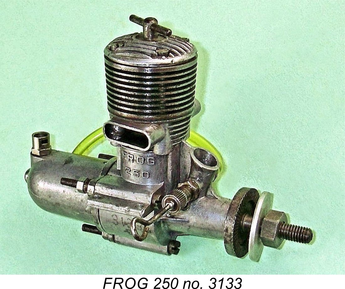 The new 2.5 cc FROG design was first described by Peter Chinn in his regular “Accent on Power” column in the July 1950 issue of “Model Aircraft”. The first published photograph of the engine was included with this article. Chinn noted that he had previously conducted a confidential test of the new model at the request of the manufacturers. He expected the engine to become available to the public in July or August 1950. This expectation was apparently fulfilled - examples evidently began to appear on British flying fields in August as anticipated.
  Indeed, below the exhaust stacks the FROG 250 was more or less a scaled-down FROG 500. It incorporated the same crankshaft front rotary valve induction system with downdraft intake and a flexible extension for the needle valve; counterbalanced one-piece steel crankshaft running in a phosphor bronze bushing; forged alloy conrod; three-bolt system for retaining the backplate (and also offering a radial mounting option); hardened steel cylinder with integrally-formed cooling fins; and cast alloy back tank. Apart from the different form of ignition, what set it apart from its larger predecessor was the design of its cylinder porting.
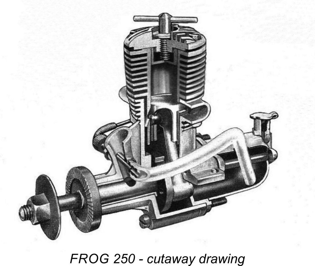
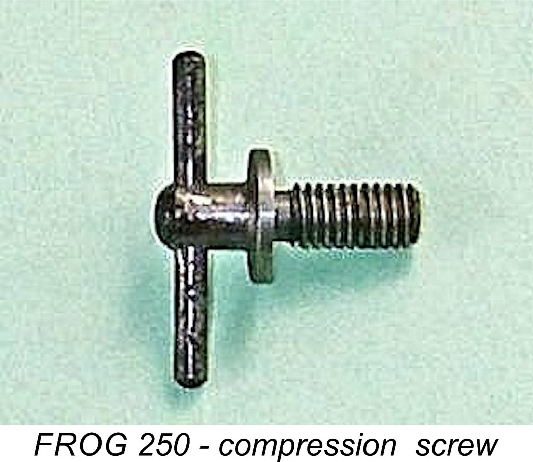 The flat-topped piston and matching contra-piston were both made of Meehanite cast iron. They were very well fitted to the bore. The compression screw was interesting in that it featured an integrally-formed expansion in the form of a disc which fitted neatly into a recess at the centre of the head. This disc limited the degree to which the compression screw could be screwed down, thus minimizing the possibility of a hydraulic lock developing in inexperienced hands. A very practical idea which some others might have done well to copy!
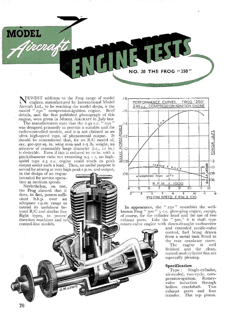 It didn’t take very long for the contemporary model engine testers to get to grips with the new FROG model. First up was Peter Chinn of “Model Aircraft”, whose unattributed
 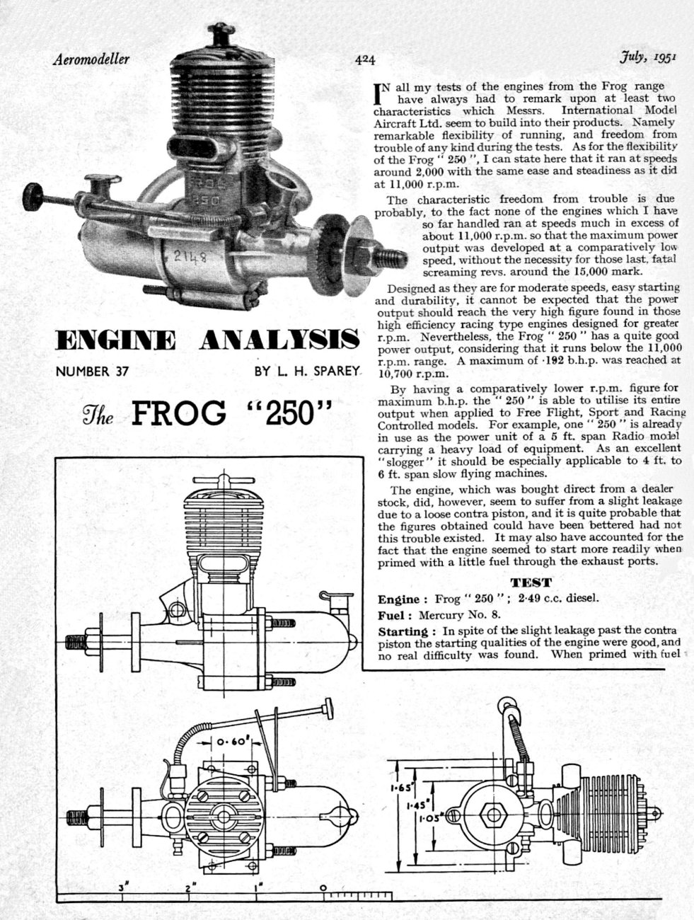 Chinn’s generally very favourable report was followed up by the appearance of a
 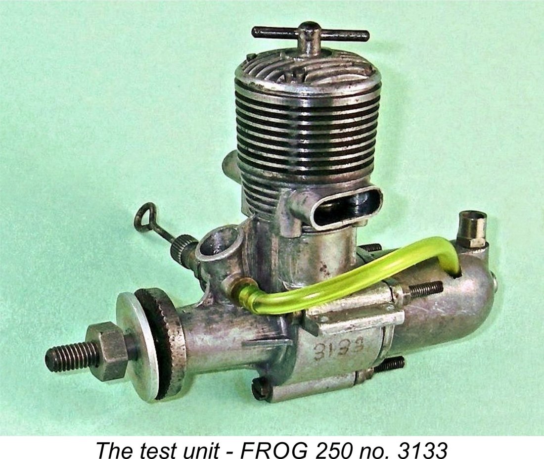 It’s always fun to have a go at second-guessing the long-ago experts! Since I had a nice example of the FROG 250 on hand in the shape of engine no. 3133, there was nothing to prevent me from putting it into the test stand to experience its characteristics for myself.
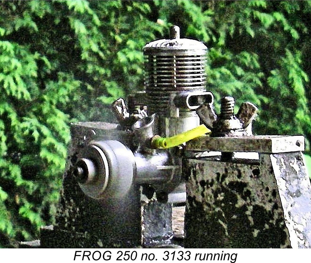
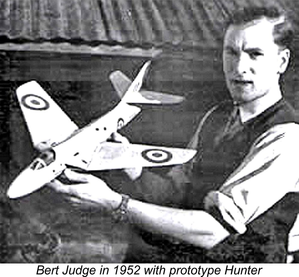 Bert Judge had left IMA in early 1952 to go to work for his former IMA colleagues at Wilmot, Mansour & Co. in pursuing the development of their
 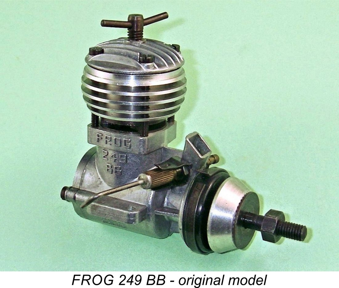 It was clear to Fletcher that Judge’s old 250 lacked the development potential to meet IMA management’s performance expectations. Accordingly, he abandoned that design altogether, starting afresh with a clean slate. The eventual result was the December 1955 market appearance of the FROG 249 BB which replaced the old FROG 250 after a respectable five-year production life for the latter model. The 249 BB was a completely new design from the ground up, bearing no design relationship whatever to its predecessor.
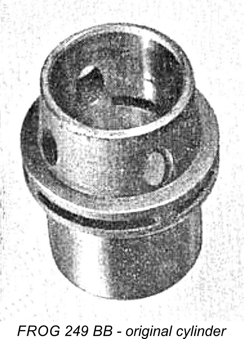
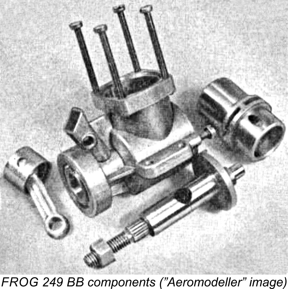 The cylinder porting was completely different from that used in the old 250. It’s clear that George Fletcher had taken note of the excellent performance achieved by John Oliver with the 1954 2.5 cc Oliver Tiger Mk. III, because the FROG 249 BB incorporated what is generally referred to as “Oliver porting”. Four rectangular exhaust ports of modest area were separated by four substantial pillars of material evenly spaced around the perimeter of the cylinder’s port belt. Four upwardly-angled transfer ports of relatively modest diameter were drilled into the bore through these pillars.
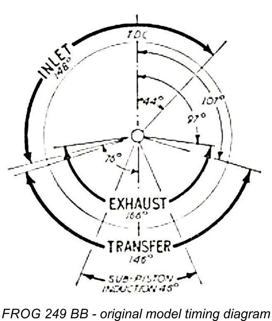
 Regardless, the four transfer ports were supplied with mixture by a bypass passage formed by the 360 degree annular space between the lower outer cylinder wall and the inner wall of the crankcase cylinder installation aperture. This arrangement was widely used by model engine designers at the time, including
 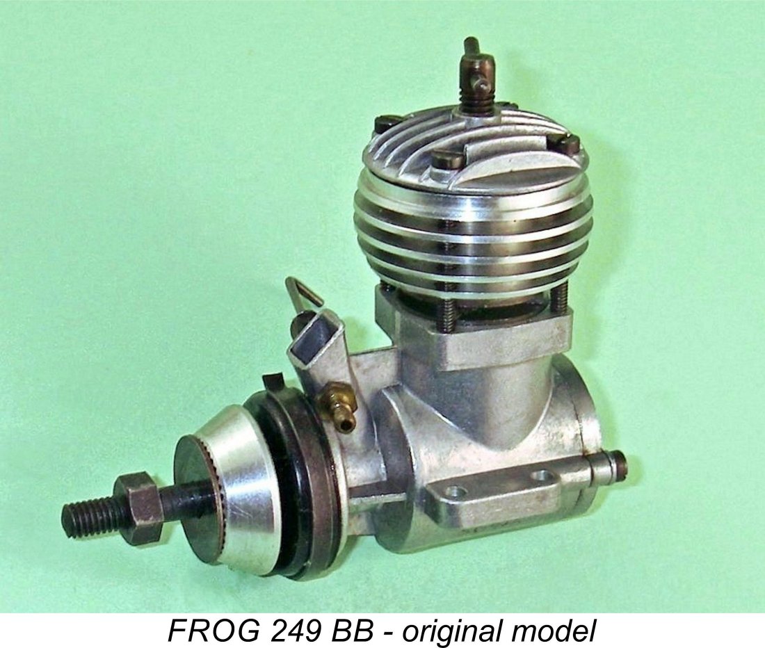 Somewhat annoyingly, the needle valve was angled rearwards on the right (looking forward in the direction of flight). While this kept the fingers well clear of the prop disc while making mixture adjustments, it was less than ideal for an engine mounted in a sidewinder orientation as featured in many control line models. A left-hand orientation would have provided far greater flexibility.
 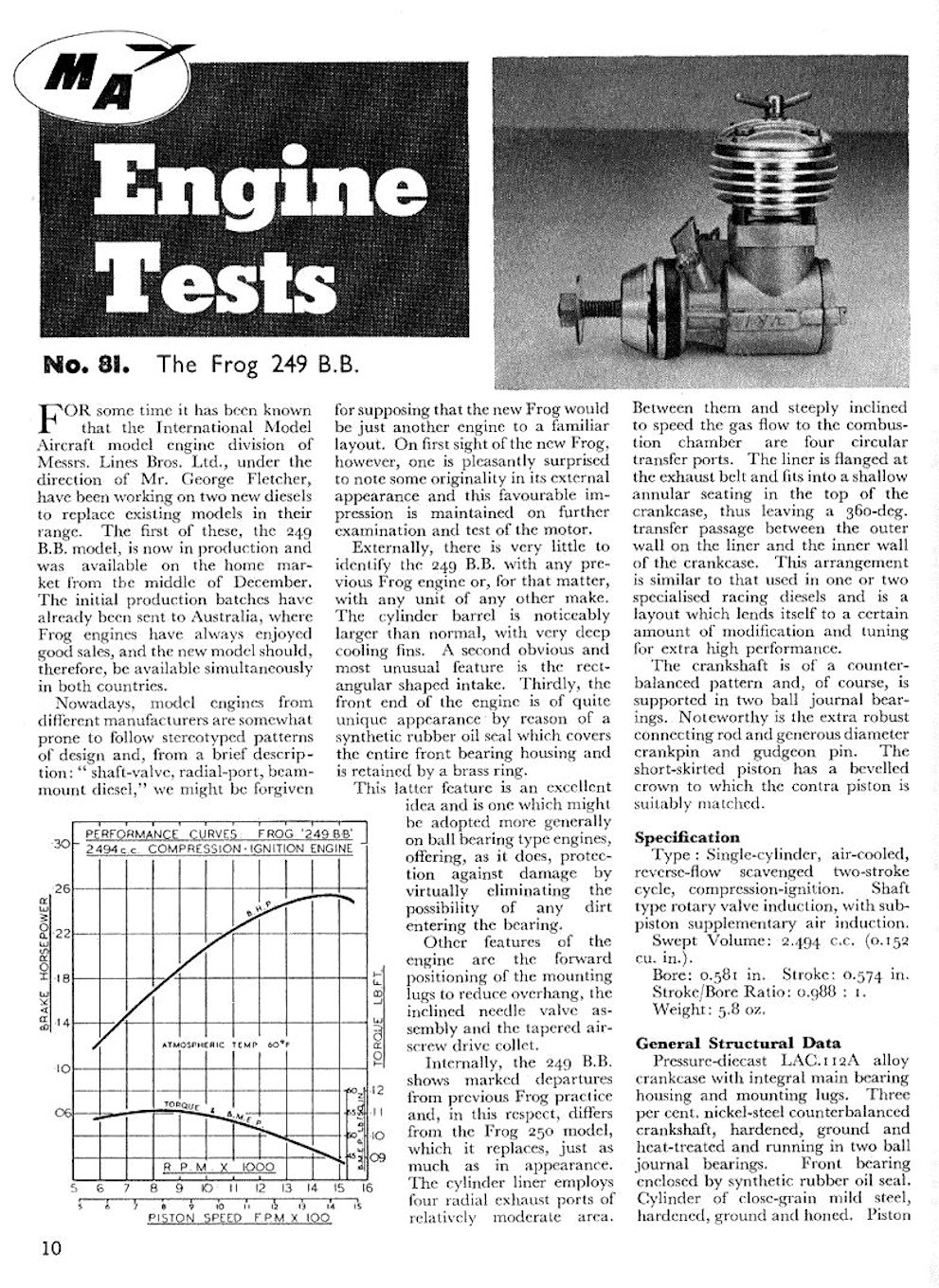 In this particular case, the competition for testing priority was a dead heat between “Model Aircraft” and “Aeromodeller” magazines! Tests by Peter Chinn and Ron Warring respectively appeared in the January 1956 issues of both publications.
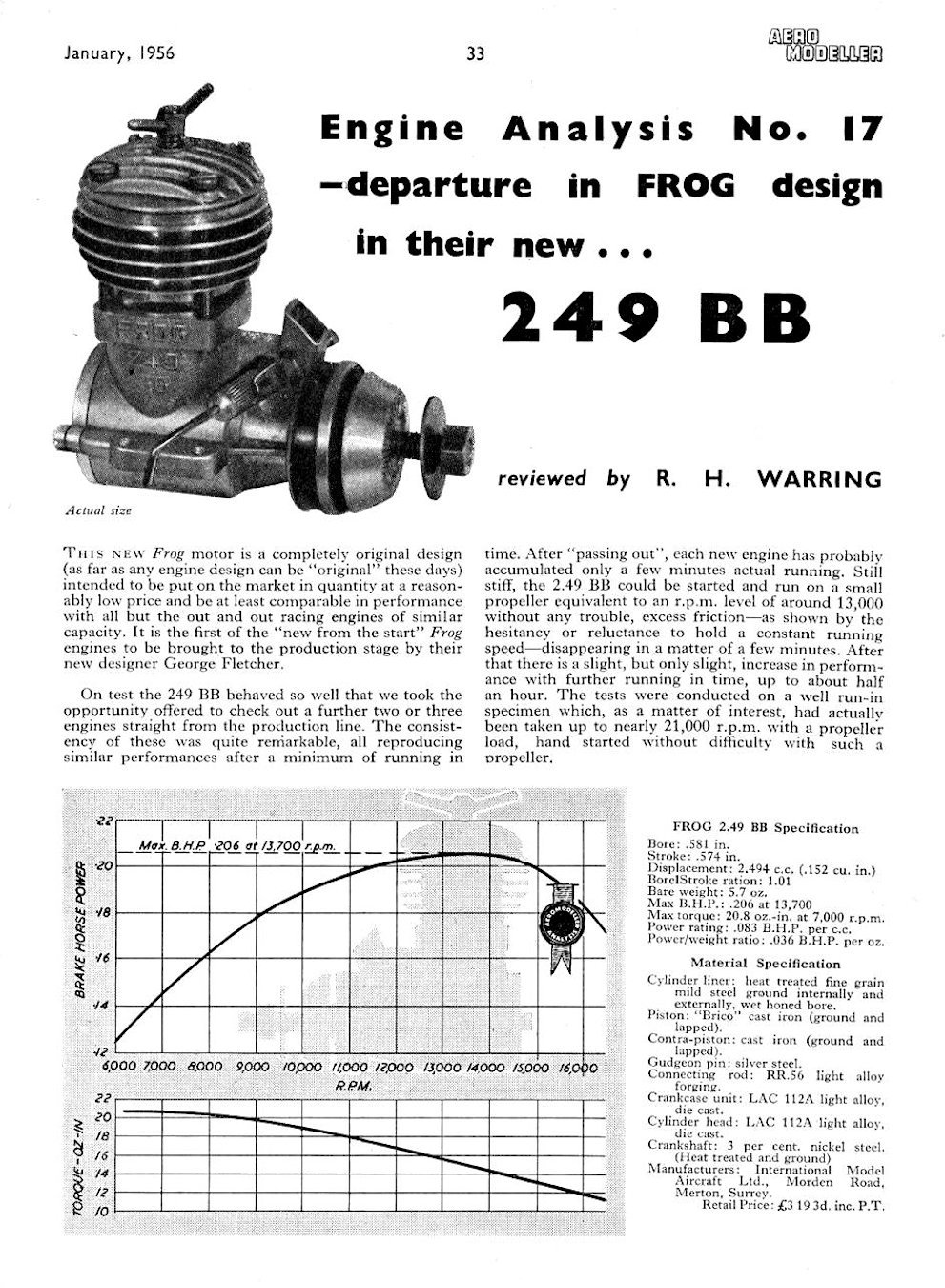 Chinn summed up the FROG 249 BB as “a worthy addition to the 2.5 cc ranks, which is unusually successful in combining pleasant handling characteristics with high performance”. A very positive accolade from a tester to whom modellers of the day listened attentively!
 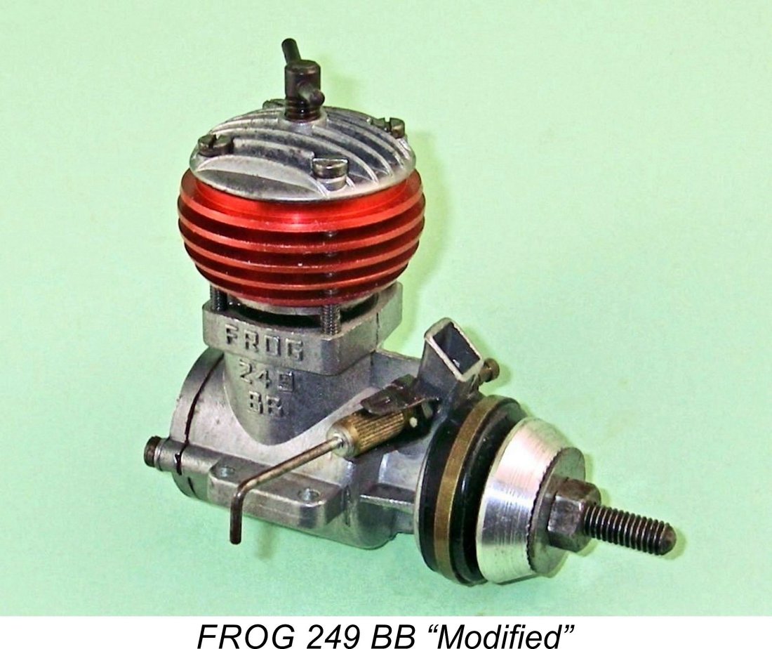 George Fletcher was immediately assigned the task of responding both positively and promptly to World Engines’ request. A concentrated development program was quickly undertaken, with a few examples of the resulting “Modified” version of the engine being sent to Peter Chinn for his independent evaluation.
 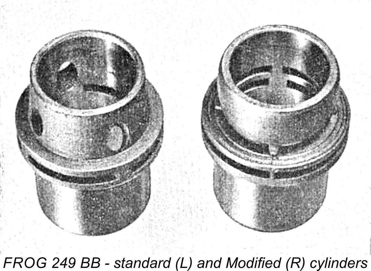 For marketing purposes, the modified engine was distinguished from its “standard” predecessor by being fitted with a red-anodized cooling jacket in place of the plain aluminium alloy jacket used on the standard model. Internally, it was essentially identical to the original model apart from the cylinder. It is thus only necessary to describe that component here - the balance of the engine was unchanged apart from a switch from cast iron to hardened mild steel for the contra piston in both versions of the engine. In addition, the diameter of the central gas passage in the crankshafts of both models was slightly reduced, presumably in response to a perception that crankshaft strength was a bit marginal.
 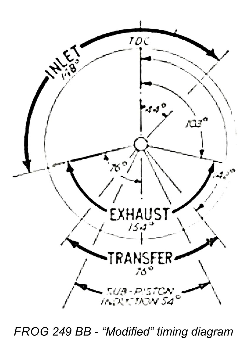 However, the timing was also drastically amended. The 166 degree exhaust period of the original model was reduced to a still seemingly long 154 degrees, extending the working portion of the power stroke to 103 degrees. Unfortunately, the designer immediately ran into the downside of the use of sawn ports, which was the impossibility of providing any overlap between exhaust and transfer ports. Despite the retention of a longer than ideal exhaust period, the transfer period was constrained to a mere 76 degrees - far less than the 146 degrees provided using the earlier Oliver porting.
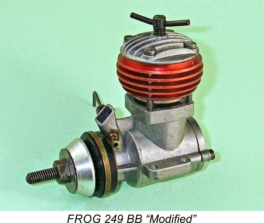 Chinn did even better than this. In his
 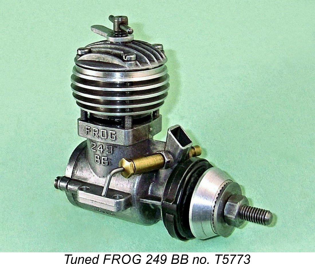 For the purposes of this experiment, I used one of the later Oliver-ported examples made by D-C Ltd. (see below) bearing the serial number T5773. As usual, I began by tearing the engine down to identify possible modifications which might enhance performance. A number of obvious possibilities immediately presented themselves.
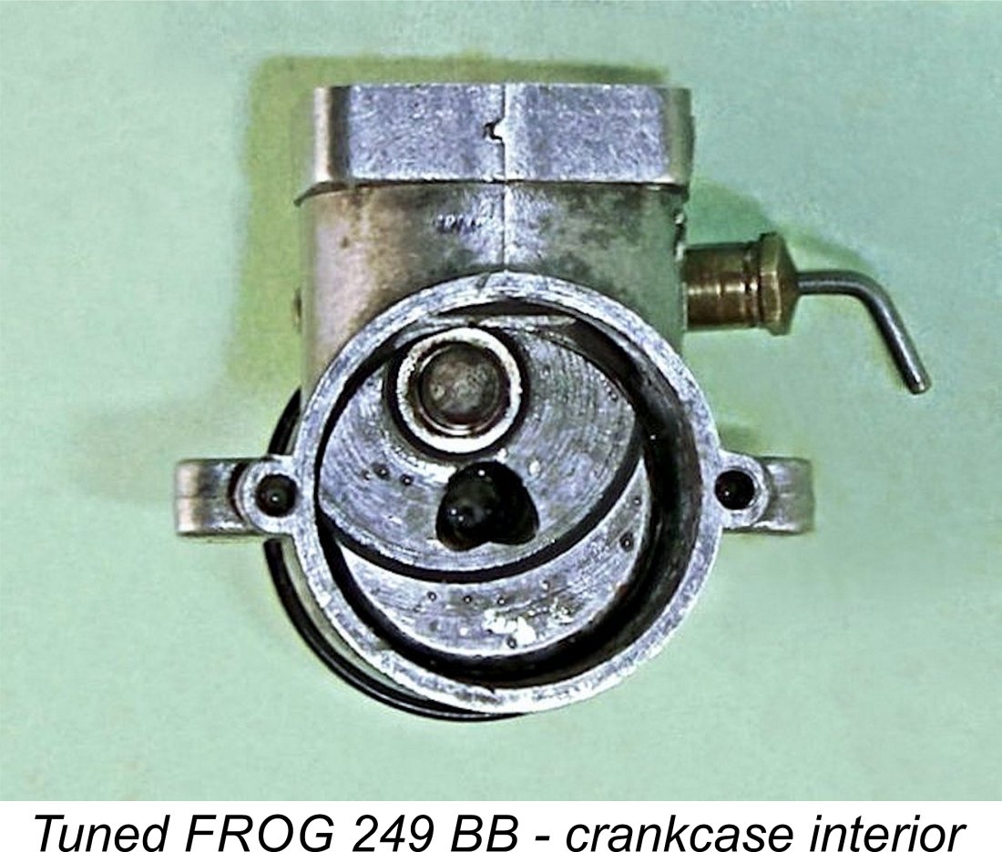 Consequently, the timing was left unchanged - I merely extended the round hole fore and aft to create a round-ended oval “race-track” configuration which overlapped the circular crankcase induction register at both ends. This increased the rates both of opening and closure of the rotary valve, also maximizing its fully-open area.
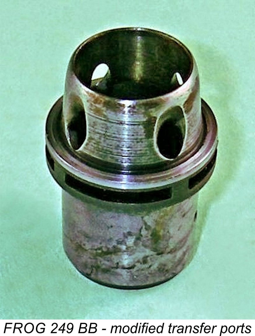 counterbalance side opposite the crankpin. These were formed at 90 degrees apart on opposite sides to created two unobstructed gas escape channels when the exit from the shaft induction passage was partially obscured by the conrod at and around bottom dead centre.
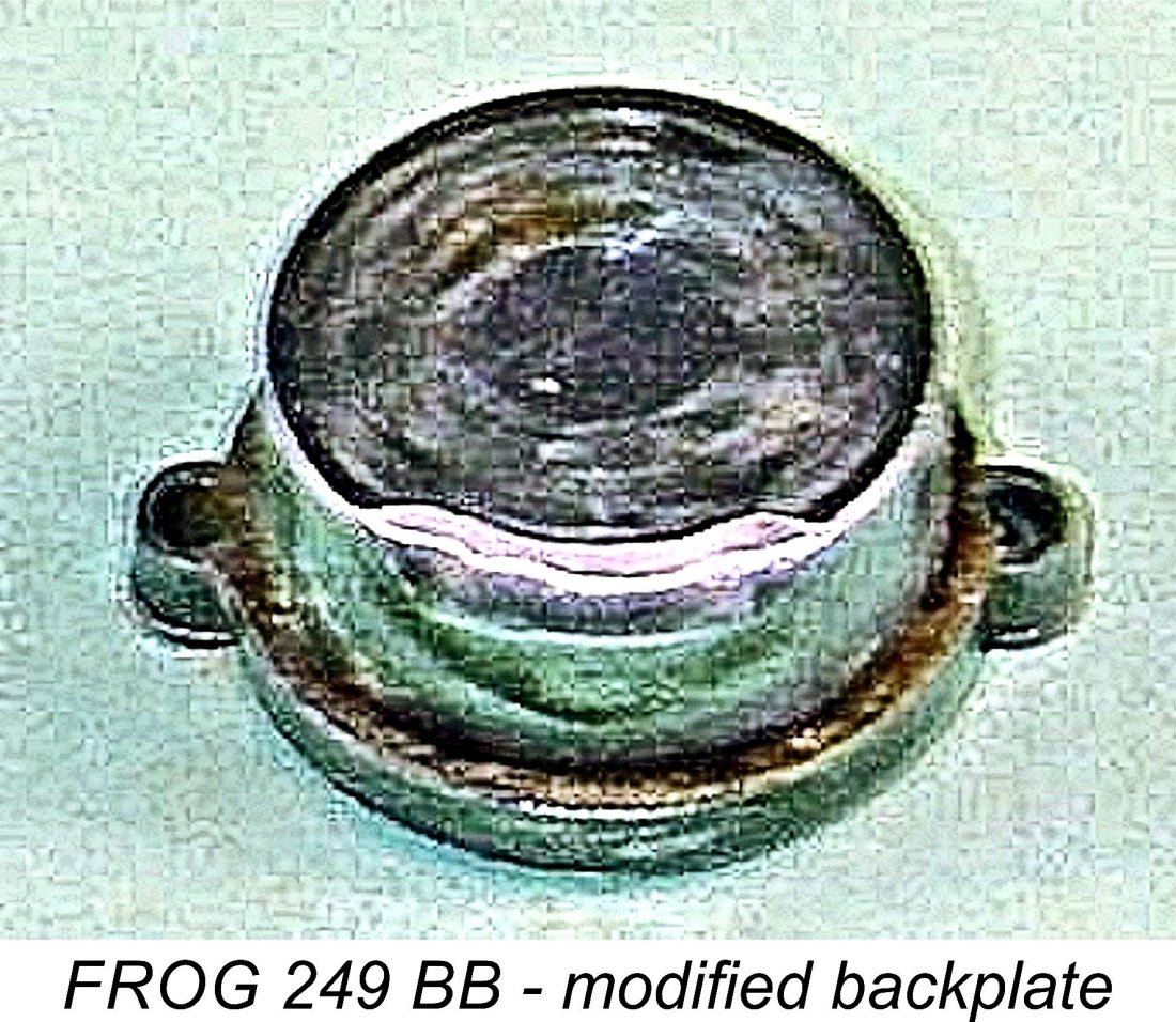 I noted previously that the backplate installation spigot greatly constricted gas access to the rear portion of the annular bypass passage. Direct gas entry into the rear section of that passage was effectively blocked by the backplate! To deal with this issue, I chamfered the upper inner edge of the backplate installation spigot. The available amount of metal does not permit this to be overdone - a breakthrough would destroy the essential crankcase seal. However, enough material can be removed to improve this situation quite considerably. The result should be a slight enhancement of the contribution of the two rearmost transfer ports to the transfer process.
 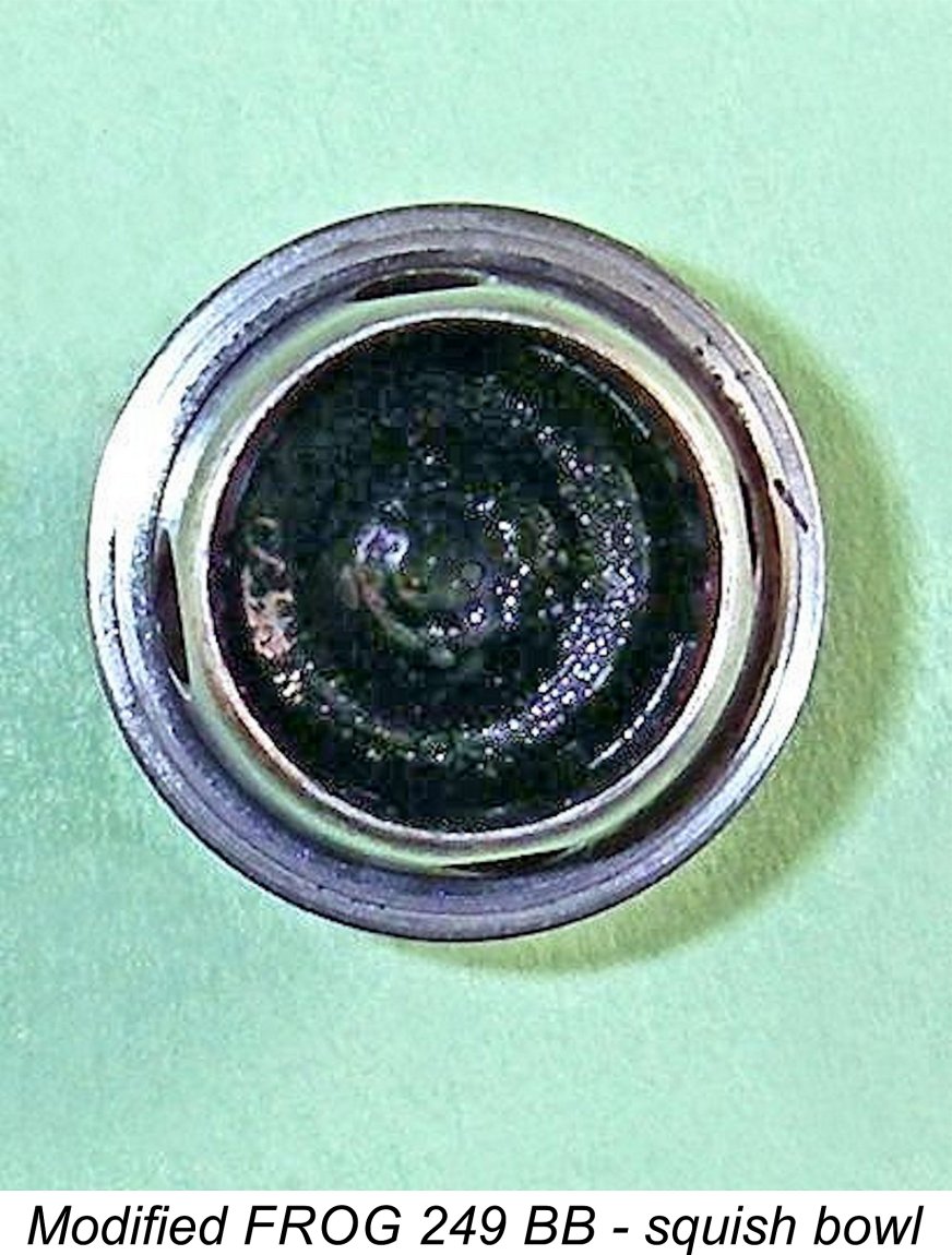 degrees while slightly increasing the sub-piston induction period. Not much of an improvement, but I’ve always subscribed to the theory that every little bit helps! Take care of all the small incremental improvements, and the combined total improvement will take care of itself!
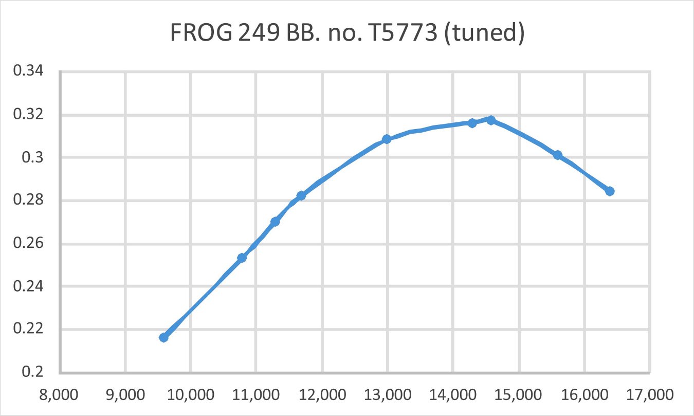
 In 1962, the Lines Brothers organization which actually owned IMA decided that the profit margin on their subsidiary’s flying model manufacturing activities was insufficient to justify continued production. Accordingly, all model engine and wood kit production ceased during that year. Naturally, this included the FROG 249 BB and also (sadly) the outstanding
 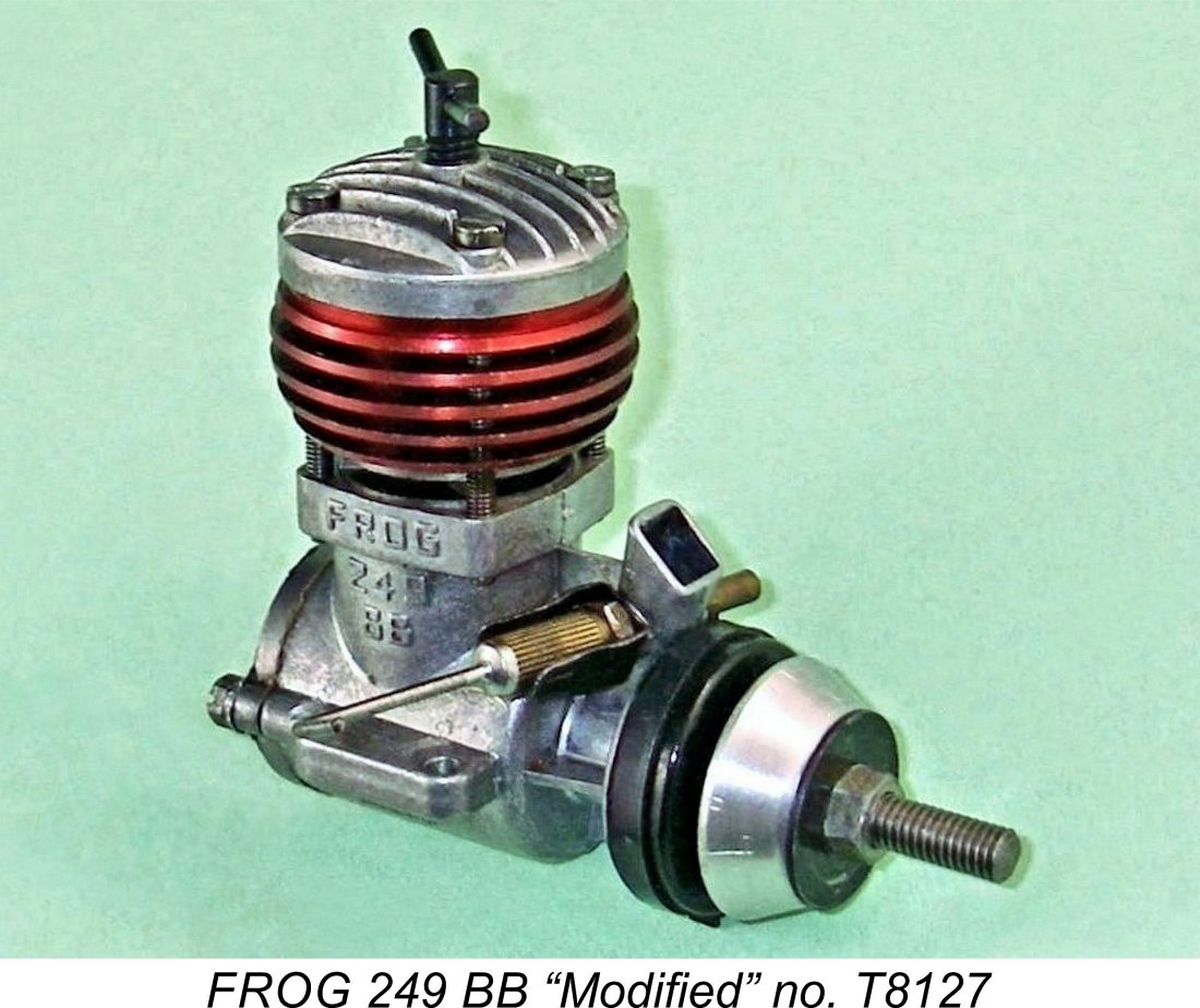 Not all of the FROG engine range went into reproduction by D-C Ltd. The abandoned designs included the venerable
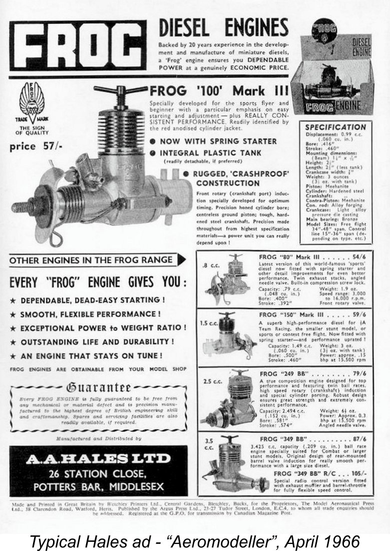
 It appears that some FROG engines remained available from dealers for some time following the end of Hales' advertising. For example, Gordon Beeby found that various FROG models continued to be listed in advertisements placed by The Model Shop (Guernsey) through to December 1973. They lasted even longer in advertisements placed by Jones Bros. of Chiswick, continuing to appear through July 1974. It's possible that they were in fact sold out before those dates and that the companies concerned simply hadn't got around to updating their advertising copy. My sincere thanks to Gordon for his greatly valued assistance!
 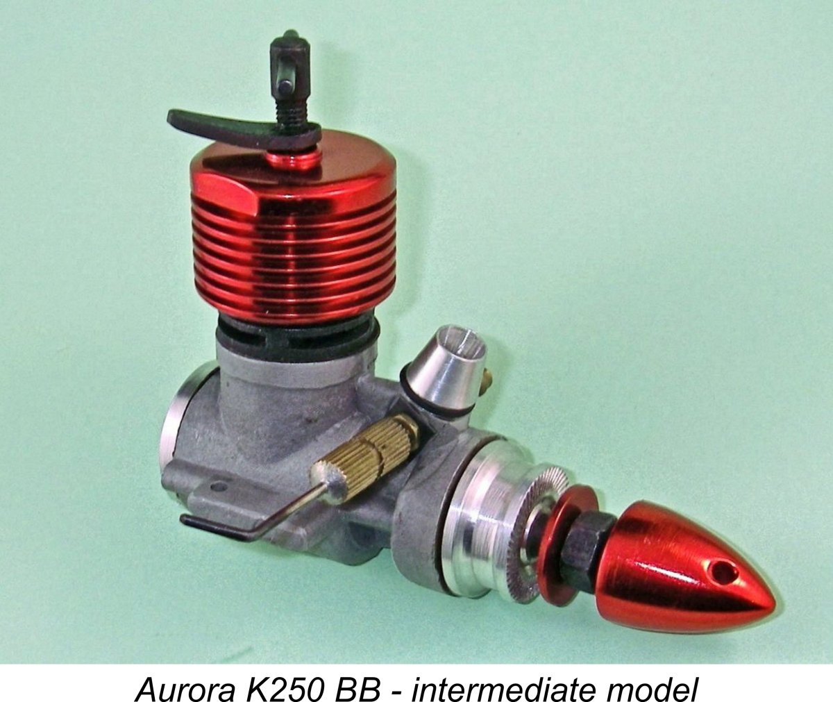 Beginning in 1966, the FROG model engines had been marketed in India by the Aurora Model Manufacturing Co. Pvt. Ltd. of Calcutta, India (now correctly rendered as Kolkata). I’ve written elsewhere about the
 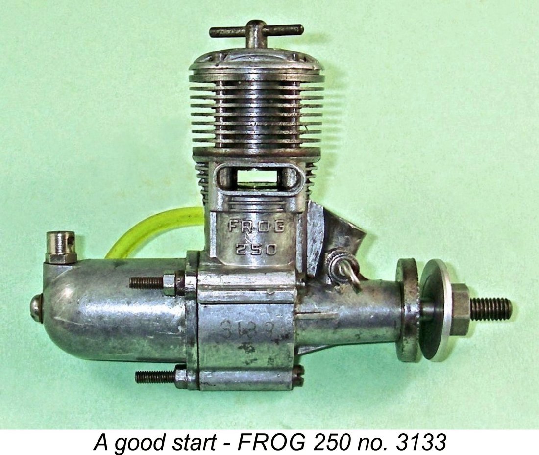 The FROG 250 of mid-1950 undoubtedly got IMA off to a very good start in the 2.5 cc displacement category. I believe that I’ve amply demonstrated that the late 1955 introduction of the original FROG 249 BB represented a significant step forward for IMA in its efforts to enhance its presence in the burgeoning 2.5 cc market. However, the FROG 249 BB “Modified’ model can only be seen as a step sideways rather than a true advance.
| |