
|
|
The Reeves H.18 diesel
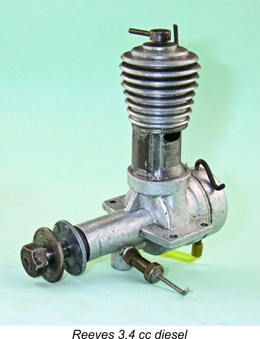
In a previous article on this website I’ve covered the initial product of the Reeves venture - the excellent Reeves 6 cc spark ignition unit which was manufactured on a small scale artisan basis in two distinct variants during the years 1946 and 1947 prior to the rise of the model diesel in British aeromodelling and Reeves’ consequent early 1948 switch from spark to compression ignition. I've also covered the Reeves 3.4 cc diesel which followed the 6 cc sparker. In another earlier article which appeared in February 2011 on the late Ron Chernich’s fascinating “Model Engine News” (MEN) website, I reviewed the Reeves H.18 diesel which was intended as an updated replacement for the rather pedestrian 3.4 cc model. Since I've covered this engine previously, why the re-publication here? Mainly because my mate Ron unfortunately left us in early 2014 without sharing the access codes for his heavily-encrypted site. Because no maintenance has since been possible, the MEN site is slowly but perceptibly deteriorating - an inevitable process which can have only one ending in the long run. I was unwilling to risk the loss of the information so painstakingly gathered on the Reeves H.18 diesel, hence the article’s re-publication here, with a little extra information thrown in. My ability to write with some authority about the Reeves H.18 is greatly enhanced by my extreme good fortune in owning several examples of this relatively rare engine. Having been so fortunate places me under an obligation to share what I’ve been able to learn with my fellow enthusiasts. Let's get right to it! Background
The Reeves venture appears to have remained pretty much a classic small-scale "garden shed" operation throughout much or all of its working existence. At some point in 1948 the business was relocated to Victoria Road in Shifnal, where it was to remain for the remainder of its active period.
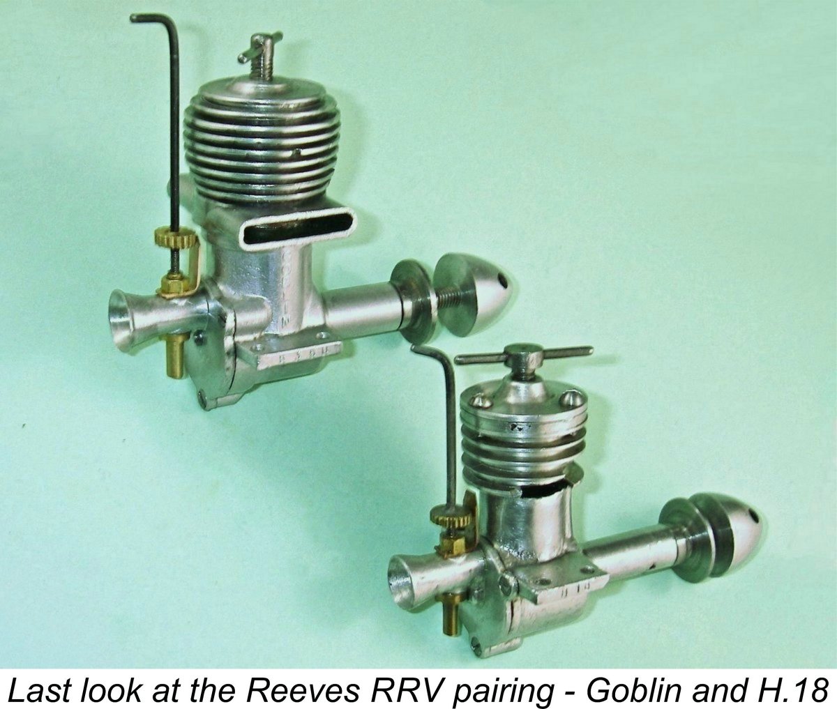
In 1948, the Mk. II spark-ignition Reeves design was replaced by the first of a series of diesel models in the form of the 3.4 cc design (actually 3.18 cc!) which was the focus of my earlier study. This was followed in late 1949 by a few examples of a 4 cc diesel model which was in effect a development of the 3.4 cc model. By this time, Reeves was trading from the Victoria Road address under the name of Reeves Model Power Units. Full details of all these earlier models may be found in the relevant articles - I do not intend to repeat that material here. Up to this point, all Reeves products had been designed around the standard plain bearing crankshaft front rotary valve (FRV) layout with updraft intake. The engine with which we are now concerned, the Reeves H.18, represented a complete departure from the previous Reeves designs in that it was a disc rear rotary valve (RRV) plain bearing engine of relatively sophisticated design. It first appeared in January 1950 and remained in small-scale production for almost 2 years at a selling price of £3 2s 6d (£3.13 in modern money). Present-day collectors, dream on........... The Reeves H.18 - Description
This brings us to one of the oddities connected with this model. When “Aeromodeller” magazine published Lawrence Sparey's test of the H.18 (see below), the above bore and stroke figures were given correctly, but the metric displacement was cited as 1.77 cc! While more in keeping than the true figure with the engine's advertised nominal displacement of 1.8 cc, this number simply cannot be reconciled with the actual bore and stroke figures featured in the design. Try it for yourself - perhaps you have a better abacus than I do!! “Aeromodeller” did get one thing right - they cited the engine's weight as a commendably light 3 ounces exactly (85 gm). My examples have all checked out at precisely that figure. To add to the mystery, the displacement in cubic inches was given correctly as 0.102 cuin!! Again, there's no way that this converts to 1.77 cc - instead, it is exactly equivalent to the engine's actual displacement of 1.67 cc! Oddly enough, no-one at “Aeromodeller” seems to have noticed this discrepancy at any time - the above incompatible figures are repeated seven years later in the entry for the H.18 in the "World's Model Engines" table which formed an appendix to the 1958 publication “Model Aero Engine Encyclopaedia”.
The fact that the H.18's true displacement was somewhat shy of the 1.8 cc figure by which it was both named and advertised represents the extension of a tendency by Edward Reeves to overstate the displacement of his products. As I showed in my companion article on the Reeves "3.4 cc" diesel, the true displacement of that model was actually only 3.18 cc! Turning now to the engine's construction, the attached exploded view extracted from the “Aeromodeller” test report shows the major details very clearly. Beginning with the crankcase, this is a gravity die-casting which incorporates the crankcase, main bearing and cylinder barrel as a single unit. The cooling fins above the exhaust ports are turned into this casting, and the barrel is internally bored out to accept a drop-in steel cylinder liner. The generously proportioned beam mounting lugs are set well above the thrust line.
The main bearing is plain and of unusual length. It has an outside diameter of 0.375 in., which combines with the 0.250 in. diameter shaft journal to create an unusually thin wall, particularly for such a long bearing. In my view, this is one of the weaknesses of this design - the long thin-walled main bearing is completely un-braced. Overall, it appears to be highly vulnerable to crash damage. But perhaps experience proved otherwise. Certainly, the long unencumbered bearing coupled with the engine's squat vertical dimensions would have made the Reeves quite attractive for use in cowled scale models. The cylinder liner is of hardened steel. It is a light push fit in the bore provided for it in the upper crankcase casting, locating on a thick flange at the top of the bore. The working liner is thus unstressed by any assembly forces - a good design feature.
From a gas flow standpoint, this arrangement is less than optimal - the lower entry into the bypass passage is greatly encumbered both by the full-disc crankweb and by the piston skirt at and near bottom dead centre. Combining this restriction with the single-hole transfer port, I would expect this design to be transfer-limited. Both the piston and the contra-piston are also of hardened steel, a material specification which was carried over from the earlier 3.4 cc model. This combination can be less than ideal for contra-pistons, since a closely-fitted steel contra tends to stick in a steel bore when hot. However, the fit in the case of my examples of the H.18 was seemingly optimized from this standpoint and no trouble was experienced from this cause on any of my engines. The use of a hardened steel piston in a hardened steel bore is another matter. This is a potentially problematic combination, as the makers of the mid-1950's J.B. engines were to learn to their cost. The problem is that running-in wear is minimal, so the fit and finish have to be pretty near perfect as constructed. Fortunately, if there was one area in which Edward Reeves was an expert, it was lapping pistons into cylinders! The fit on two of my engines, like that on both of my Reeves 3.4 cc models, is beyond reproach - no sign of "stiction" at any point in the stroke, and yet the engines seem to hold their compression forever despite having obviously received a fair bit of use in the distant past. That having been said, the third example which I subsequently acquired was far less well fitted. It was seemingly unrun, being distressingly tight throughout the stroke. Indications were that it featured a more or less cylindrical bore with no appreciable taper. It would start up OK, but any attempt to lean it out resulted in progressive tightening and eventual seizure. The fact that this example has no serial number may imply that it was assembled near the end of Reeves production using parts which were less carefully fitted than the earlier numbered examples. I had to relieve this issue by undertaking a little careful lapping of the bore, after which the engine ran fine, albeit still a little on the tight side. The piston is of relatively lightweight construction, with fairly thin walls - a significant technical advance from the excessively heavy piston used in the earlier 3.4 model. The fully machined hardened steel con-rod is mounted on a silver steel gudgeon (wrist) pin which is pressed into the piston from the rear in order to prevent fouling of the transfer port at the front. Con-rod length is relatively short, accounting for the engine's somewhat squat appearance. In fact, the piston skirt is relieved at the front and rear to clear both the disc valve and the crankweb at bottom dead centre. The engine does not feature sub-piston induction.
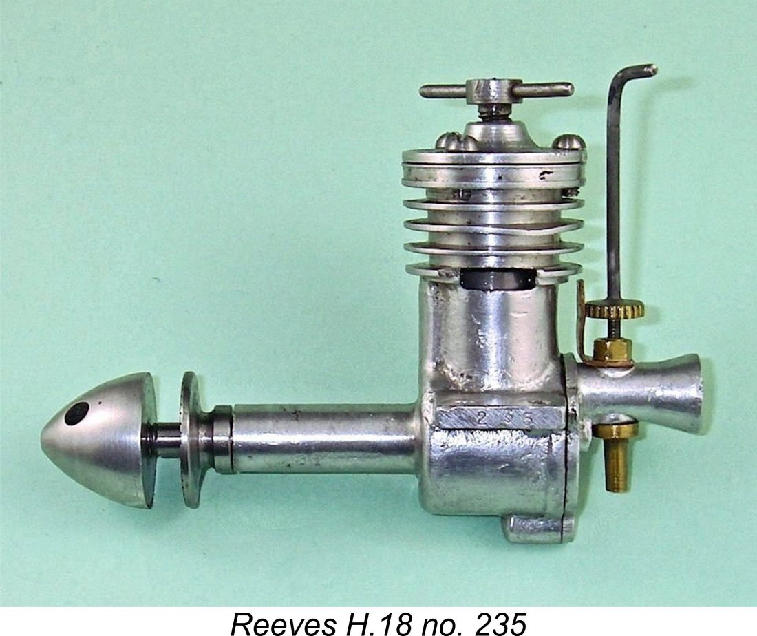
The crankshaft is a one-piece hardened steel component having a counterbalanced full disc crankweb. The main crankshaft journal is solid throughout with no central drilling to save weight. It is an outstanding fit in the plain bearing which supports it. As noted earlier, journal diameter is 0.250 in. The prop mounting thread is 2BA, with a conventional spinner nut used to secure the prop. The prop driver on illustrated engine no. 235 is of steel. It is located on a 30 degree included angle taper machined onto the front of the crankshaft. My slightly earlier example no. 200 has a similarly-mounted prop driver which is nicely machined from aluminium alloy. Images of other examples show a similar alloy prop driver. Engine no. 235 is not an isolated example - the engine illustrated by Mike Clanford in his well-known A-Z book also has a steel prop driver, as does my more recently-acquired un-numbered example. Other examples, including the one tested by Sparey, were fitted with a die-cast prop driver having an annular ring of small cast-on protrusions to prevent prop slippage. A similar design had been used on the 3.4 cc diesel which preceded the H.18, implying that this type of prop driver may have been used on the early examples of the H.18.
Turning now to the backplate, this is another gravity die-casting which is secured to the rear of the crankcase with three countersunk-head 10BA screws - a very neat approach. The wedging action of the countersunk heads must place considerable stresses upon the relatively insubstantial backplate mounting "mouse ear" lugs through which they pass, and I would not recommend tightening them too hard in case the lugs are split by these wedging forces. With countersunk heads, overly-snug tightening is not necessary in any case - the wedging action discourages loosening.
It's unclear whether or not this was done during manufacture or whether it is the work of a knowledgeable owner, but there's no doubt at all that it should improve performance significantly, to the point that it would not really appear to be an optional feature if the full potential of the design is to be realized. At the other end of the induction cycle, the disc valve opens unusually early - around 15 degrees past bottom dead centre. The modified timing of the induction period is thus a full 180 degrees.
One feature upon which I’ll be commenting further in due course is the use of an unusually coarse taper on the tip of the needle. Admittedly the 8BA thread is very fine, which should facilitate the use of such a taper, but even so it appears that the taper could have been made a little finer with advantage. Overall, the engine has a very neat and quite pleasing appearance. As usual with Reeves engines, the external finish of the castings can most fairly be described as "utilitarian" - the castings themselves are a bit rough, with a few blow-holes in evidence, but appearance is significantly improved by the application of a light polishing treatment following a certain amount of hand-filing to remove burrs and flashing. This is typical of Reeves products - they were always best finished inside where it really counted. None of my examples of the H.18 can be faulted in the latter regard.
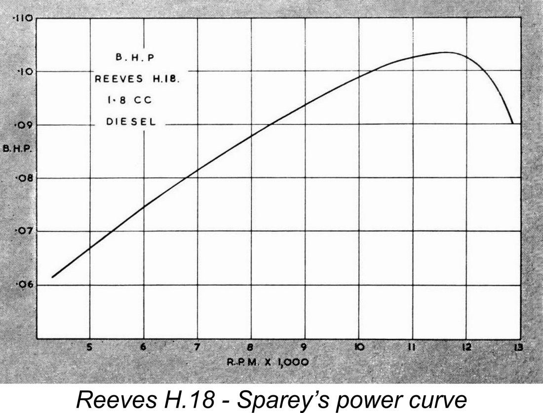
The engines also bear a serial number which is stamped on the end of the opposite lug. My illustrated example bears the number 235, which is currently the highest confirmed serial number for one of these engines. My second numbered example bears the serial number 200. Kevin Richards reported having owned two of these units in the past bearing the serial numbers 161 and either 173 or 178 (the strike of the last digit was a little ambiguous). If anyone can provide any more H.18 serial numbers which might help to estimate production figures, I'd be most grateful. At present, all I can say is that we appear to have hard evidence for the production of at least 235 examples. Of course, it's possible that the serial numbering sequence was started at 100 - a common approach applied by manufacturers to inflate their perceived production rates. If this was the case, the number of confirmed examples would be reduced to a minimum of 135 units. We'd need a confirmed two-digit serial number to settle this question. Just to confuse the issue, we know that the odd engine was released with no serial number at all! The third example which I acquired bore no markings whatsoever - neither the H.18 designation nor a serial number. As mentioned earlier, this example was far less well-fitted than my other two engines, being distressingly tight and prone to seizure when leaned out. It seems likely that this was an "afterthought" unit assembled near the end of production to use up residual components already on hand - such examples may have been less carefully fitted than their predecessors. The Reeves H.18 in the Modelling Media The Reeves range appears to have remained pretty much below the radar of the mainstream model aeronautical media of the day. This was no doubt due in large part to its "cottage industry" origins and associated modest production rates which prevented the range from achieving any real prominence in the national marketplace. Consequently, the H.18 appears to have largely escaped the attention of the model engine commentators of the day. One particularly odd circumstance is the fact that the engine was completely omitted from the 1951 revised edition of Col. C. E. Bowden's book, “Diesel Model Engines”, despite the fact that its then-discontinued predecessor, the Reeves 3.4 cc model, was covered in some detail. Writing many years later, the late O. F. W. Fisher mentioned the H.18 in passing on page 40 of his 1977 publication “Collector's Guide to Model Aero Engines”, noting simply that he had used one in 1954 along with an Elfin 1.49 BB to Apart from the maker's periodic advertisements, the one contemporary appearance of the engine in print that has come to my attention is the published test by Lawrence Sparey which appeared in the March 1951 issue of “Aeromodeller”. Sparey had little but praise for the engine's design and construction, commenting particularly upon the outstanding piston-cylinder fit. He reported that starting was "very good under all conditions" and that running was "smooth and consistent at all speeds, with good flexibility of needle control". In the latter context, he noted that the rear-mounted carburettor with its extended needle valve was very convenient from an operational standpoint. Sparey reported an unusually precise measured peak output of 0.1034 BHP @ 11,700 rpm. While the indicated specific output of 0.062 BHP/cc is nothing for us to get excited about today, it was a perfectly acceptable performance by 1951 standards for a compact 3 ounce plain bearing engine of 1.67 cc displacement. Writing in the context of his own times, Sparey actually characterized this performance as "extremely good".
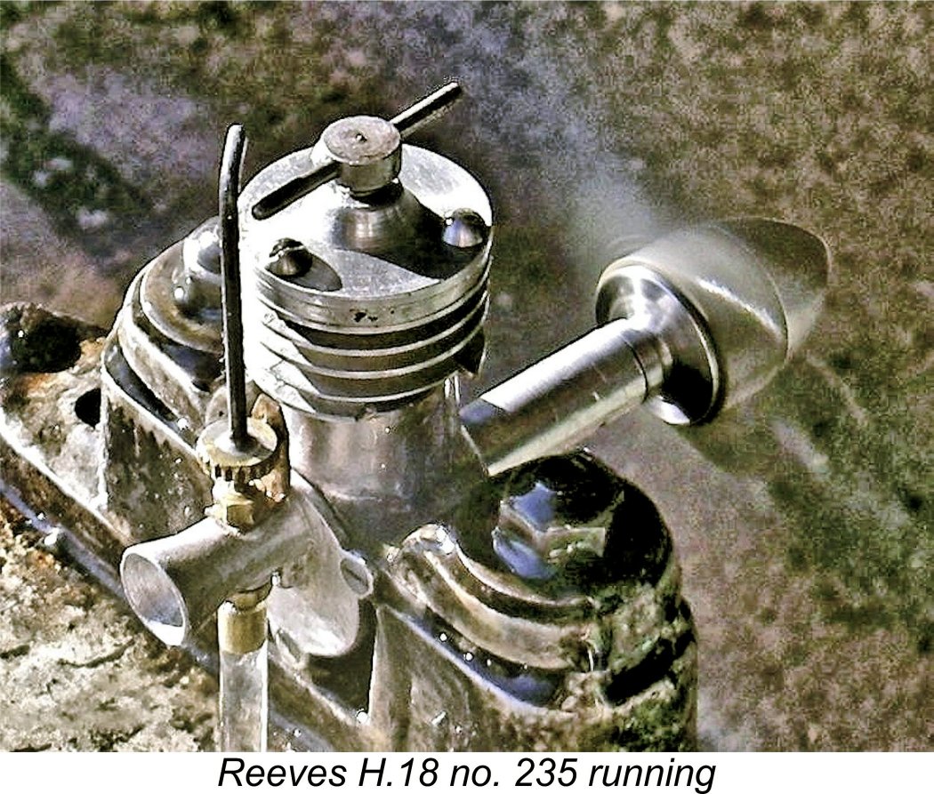
Sparey reported no mechanical troubles during the test (which he usually did when they occurred), He summarized his findings by stating that the H.18 "seems satisfactory from all points of view". About as positive an endorsement as Edward Reeves might reasonably have expected! As far as the record shows, the rival “Model Aircraft” magazine never ran a published test on the H.18. The Reeves H.18 Revisited Having a well set-up example on hand that appeared to have already received quite a bit of use in the form of engine no. 235, I decided that nothing would be lost by giving it a few more runs myself to see how far Sparey's results could be confirmed by present-day experience. I had tested the same engine back in late 2010 when gathering material for my original publication on MEN, but decided that I should repeat the test in order to add authority to this revised edition of the article.
Sparey's test report cited the recommended airscrews as 8x6 or 8x8 for control line and 9x4 for free flight. I therefore elected to test props lying more or less in that range as well as some slightly smaller sizes to allow the engine to reach airborne speeds on the bench. Not having any idea about the correct settings at the outset, I set the controls by feel and guesswork and relied on port priming for the initial start. As events proved, I guessed about right for the compression but had the needle set way too rich to begin with. This quickly got the engine pretty wet, and I had to shut off the fuel supply and reduce compression to clear things. But eventually I got things sorted to the point where a start was achieved.
My modifications to the needle taper appeared to have been very effective. It proved to be far easier to zero in on the optimum setting than my notes show it to have been on the earlier occasion. Once the setting was established, the needle held that setting firmly. After the initial run, I had no further starting difficulties whatsoever. I found that priming was quite unnecessary at any time - a couple of choked flicks got the engine going almost immediately every time. A very easy-starting engine indeed!! When the engine was cold, it was necessary to pull the needle out 3 or 4 clicks and raise the compression slightly, restoring running settings as the engine warmed up. Hot restarts were immediate at running settings. In performance terms, the engine proved to be no world-beater, but it did shift a meaningful amount of air and ran very smoothly at all speeds tested. Vibration levels were quite modest - certainly well within acceptable limits. Results achieved on the day were as follows:
The power curve derived from the above figures is far smoother than the one generated by my initial 2010 series of tests, due no doubt to the more precise settings made possible by the greatly improved needle valve response. The data generally confirm the performance levels reported by Sparey, although my test engine seems to have peaked at a somewhat lower speed. As can be seen, I clearly reached the engine's peak. The above curve implies that this particular example probably peaks at around 0.101 BHP @ 10,500 rpm or thereabouts - near enough to the figures reported by Sparey. This is very nearly the same output as that obtained during my previous test of the Reeves 3.4 cc diesel, albeit at almost double the rpm. So this design represented real progress by Reeves in performance terms. It's also apparent that Sparey was quite correct in stating that the engine has an unusually flat peak to the power curve. My test engine appears to deliver 95% of its peak output at all speeds between 8,900 and 11,400 rpm - an unusual degree of operational flexibility. Having established the peak, and not wishing to risk damage, I decided against pushing the engine any faster on an even smaller prop than the 7x4 since it was already past its peak on that load.
It must be said that the performance figures cited above are difficult to reconcile with the maker's reported airscrew recommendations. In a control-line context, it would take a pretty "fast" 8x6 to get the engine up to the approximately 9,300 ground rpm which would be required for the achievement of peak performance in the air. An 8x8 would completely kill the engine in performance terms. I'd probably go for an 8x6 cut down to around 7½x6 for best results. If the engine got this up to 11,000 rpm in the air, as seems likely, a theoretical airspeed of 50 mph should be achievable in a reasonably "slippery" airframe - perfectly acceptable for a lightweight 1.67 cc engine of 1950 vintage! In a free-flight context, where airborne pickup is considerably less than in control-line, the recommended 9x4 again seems pretty excessive based on these tests. For maximum performance, I'd go no larger than an 8x4. This said, the unusually flat power curve indicated by the tests reported above would mean that operating even 2000 rpm below the peak would represent less than a 10% power shortfall below the maximum. In most practical non-contest applications, this would probably be scarcely noticeable. Viewed in this context, the maker's recommended prop sizes seem a little less unreasonable for general-purpose use. The Rest of the Tale…….. ……...may be quickly told. Following its introduction in January 1950, the H.18 remained in production for some time, still being advertised in “Aeromodeller” in November of 1951. However, by January of 1952 the company was no longer advertising either the H.18 or any other specific model. Instead, they were hinting at new models yet to come. The implication is that production of the H.18 ended in late 1951.
This unfavourable test outcome probably sealed the doom of the Reeves range. Actually, the fact that Chinn could not establish contact with them in connection with his then-unpublished test of the Goblin implies that Reeves Model Power Units may have already been in the process of winding up their affairs at the time of Chinn's test. They must have had some already-manufactured engines still to liquidate, because they continued to advertise sporadically, the final advertisement appearing in the December 1952 issue of “Aeromodeller”, still promoting the Goblin. A latter-day re-appraisal of the Goblin appears elsewhere on this website.
Following the initial publication of this article, I was delighted to hear from a former owner of my then recently acquired Reeves H.18 serial number 235. This was none other than Graham Podd, who is well known to collectors and engine builders alike. Amazingly, Graham still had the original box in which this particular engine was supplied! He had acquired the boxed engine from a non-modelling individual who had found it languishing in the roof space of his house and was going to throw it out before being advised (correctly) that it would fetch a good price on eBay! Graham had kept the box strictly to preserve it but was kind enough to pass it along to me, thus re-uniting the engine with its original packaging. The engine had clearly spent many years in the attic, and the box has suffered accordingly. However, the label remains in good enough condition to be fully legible. It confines itself to an Graham also advised that he had a distinct variant of the Reeves H.18, the existence of which had previously escaped my attention. This has a more substantial cylinder head and thicker cooling fins. In addition, it has a fully machined aluminium prop driver. It bears neither a serial number or any form of model identification. It appears to be unused. Graham advised that the backplate does not feature any additional internal machining to improve the induction cycle. The absence of a serial number suggests that this is most likely another "afterthought" example assembled near the end to use up residual components still on hand. However, there’s no way of confirming this. Regardless, my sincere thanks to Graham for making me aware of this seemingly-rare variant. Conclusion
There's no question that the engine was extremely well-made where it counted and that if carefully treated it was well able to give good service. In addition, it is a refreshingly out-of-the-rut design in the context of its time, thus being a most interesting model to add to any collection of early British diesels. Just be prepared to pay somewhat above the odds if one does turn up! Finding one is not easy, but anyone acquiring an example will be adding something of great interest to their collection! ________________________________ Article © Adrian C. Duncan, Coquitlam, British Columbia, Canada First published on MEN February 2011 This revised edition published here January 2024 |
||
 In this article I’ll present some information regarding a 1950 attempt by one of Britain’s small-scale early post-WW2 artisan model engine manufacturers to bring his model diesel designs up to date by comparison with his contemporary competition. I’ll be reviewing the rare Reeves H.18 diesel of 1.67 cc displacement.
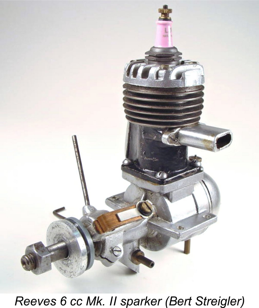
 The Reeves H.18 bore little or no resemblance to any previous Reeves product. It was a far more up-to-date design featuring RRV induction as well as short-stroke internal geometry. As events were to prove, it was to be the only short-stroke design ever marketed by Reeves. Bore and stroke were 0.510 in. (12.95 mm) and 0.500 in. (12.70 mm) respectively for a calculated displacement of 1.67 cc (0.102 cuin.). These figures are confirmed by actual measurements taken from my own examples.
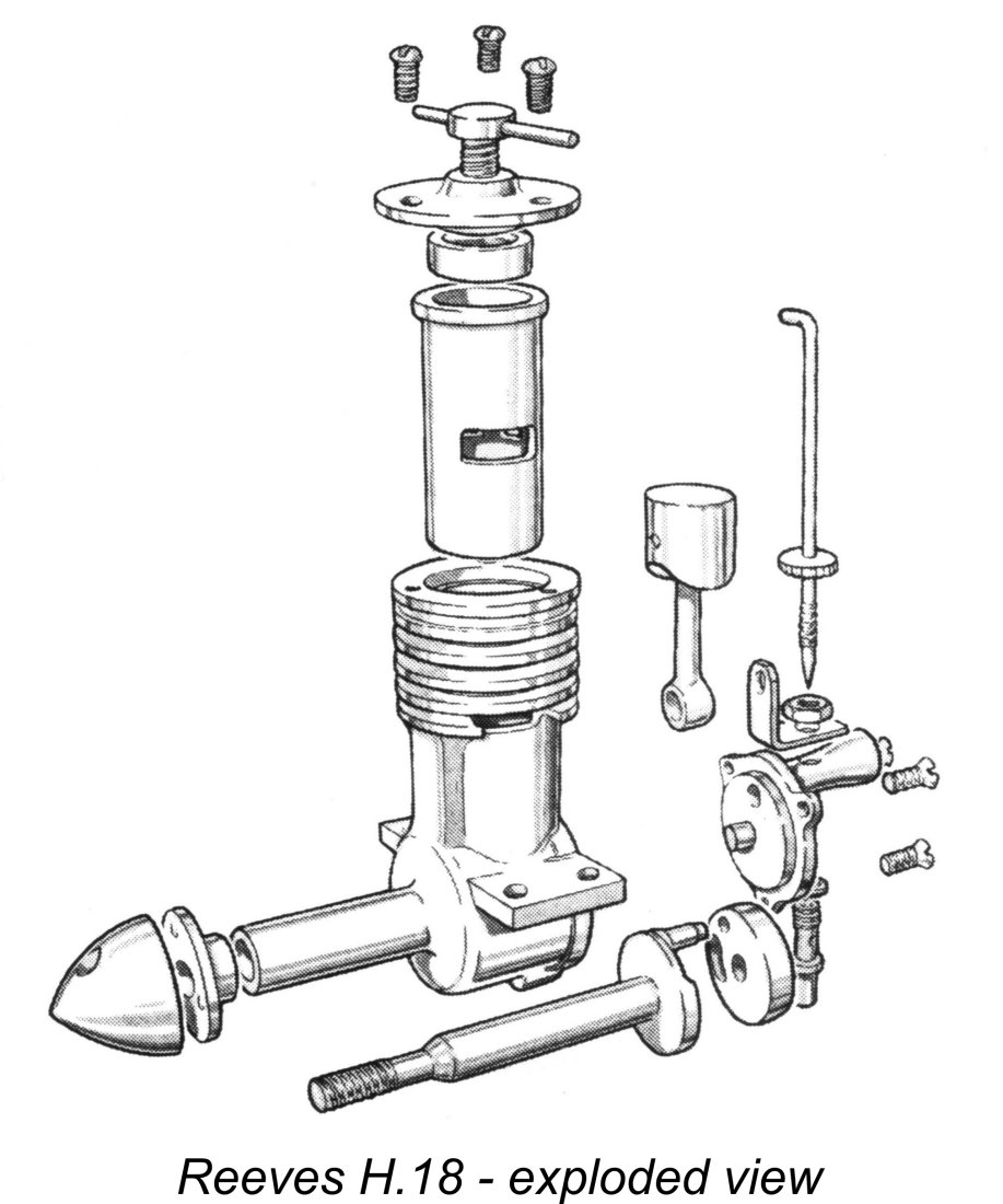 The fact that the displacement in cubic inches was given correctly makes it appear that this whole inconsistency arose because of a simple uncaught error in the typesetting of Sparey’s original test report - a 7 was inadvertently switched for a 6, raising an intended 1.67 cc displacement to 1.77 cc. Unfortunately, no-one caught it, either then or later. The real mystery is the reason why both the Reeves H.18 and the later Goblin 2.45 cc model were included in the previously cited 1958 table at all when they had both been out of production for over 5 years!
 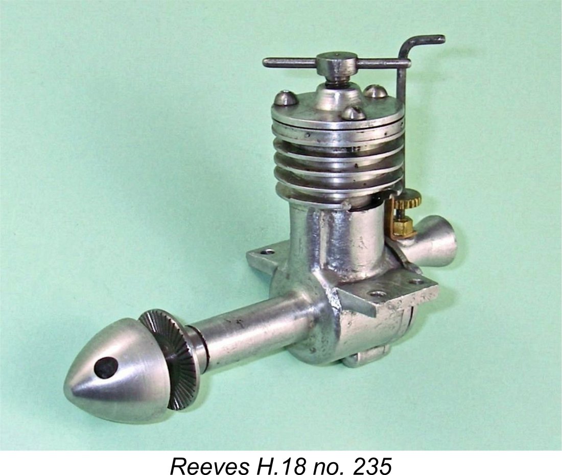 The crankcase incorporates a single bypass passage at the front - the external "bulge" which accommodates this is clearly visible. Two exhaust ducts are formed in the casting at exhaust port level, one on each side. Three 6BA tapped holes are provided at the top for retention of the turned alloy cylinder head, which in turn carries the steel compression screw on a 3/16x24 Whitworth thread. This control is generously proportioned and very comfortable to use, although a finer thread might have been preferable.
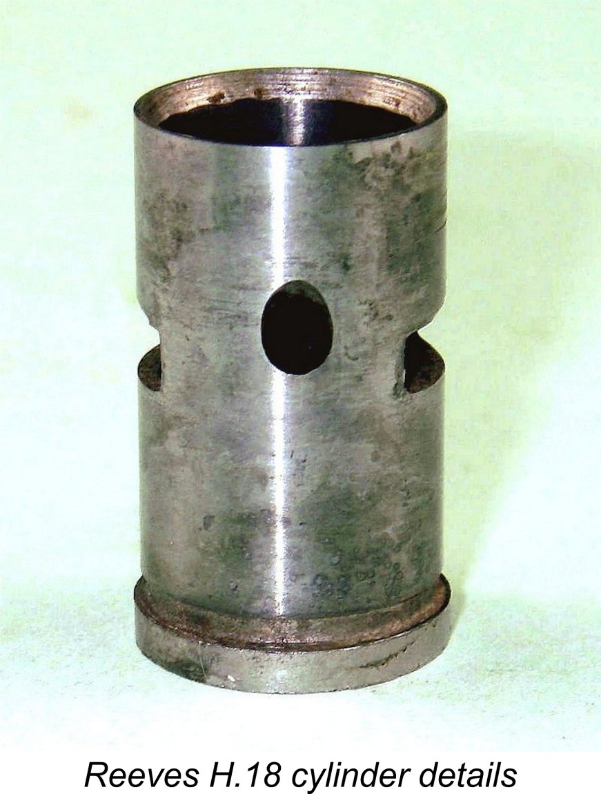 The cylinder has two large rectangular exhaust ports, one on each side, which feed exhaust gas into the two ducts in the case mentioned earlier. A single transfer port in the form of an upwardly-angled drilled hole of modest dimensions is provided between the two exhaust ports at the front. This transfer port overlaps the exhaust almost completely, giving a very short blow-down period. It is fed through the previously-mentioned bypass passage at the front of the crankcase, making the cylinder a one-way fit in this model.
 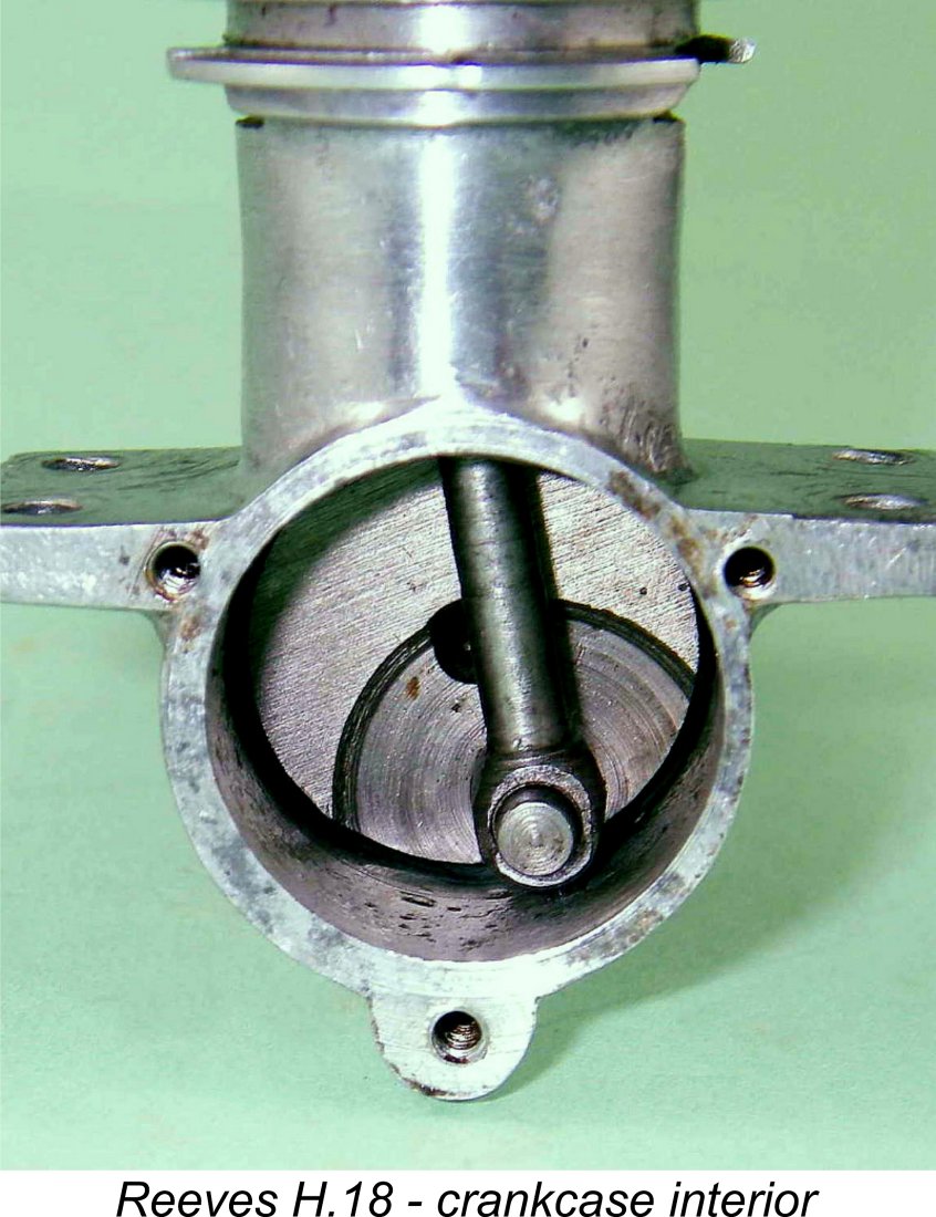 Once again, the use of a hardened steel rod can cause problems with premature wear on the gudgeon pin and/or crankpin, but the bearings at both ends of the Reeves rod are both relatively long and extremely well finished. Accordingly, wear should not be as much of a problem with this engine as it is with some others. Both top and bottom rod bearings remain very well fitted in both of my two previously-used examples despite the previous running time which they have clearly accumulated.
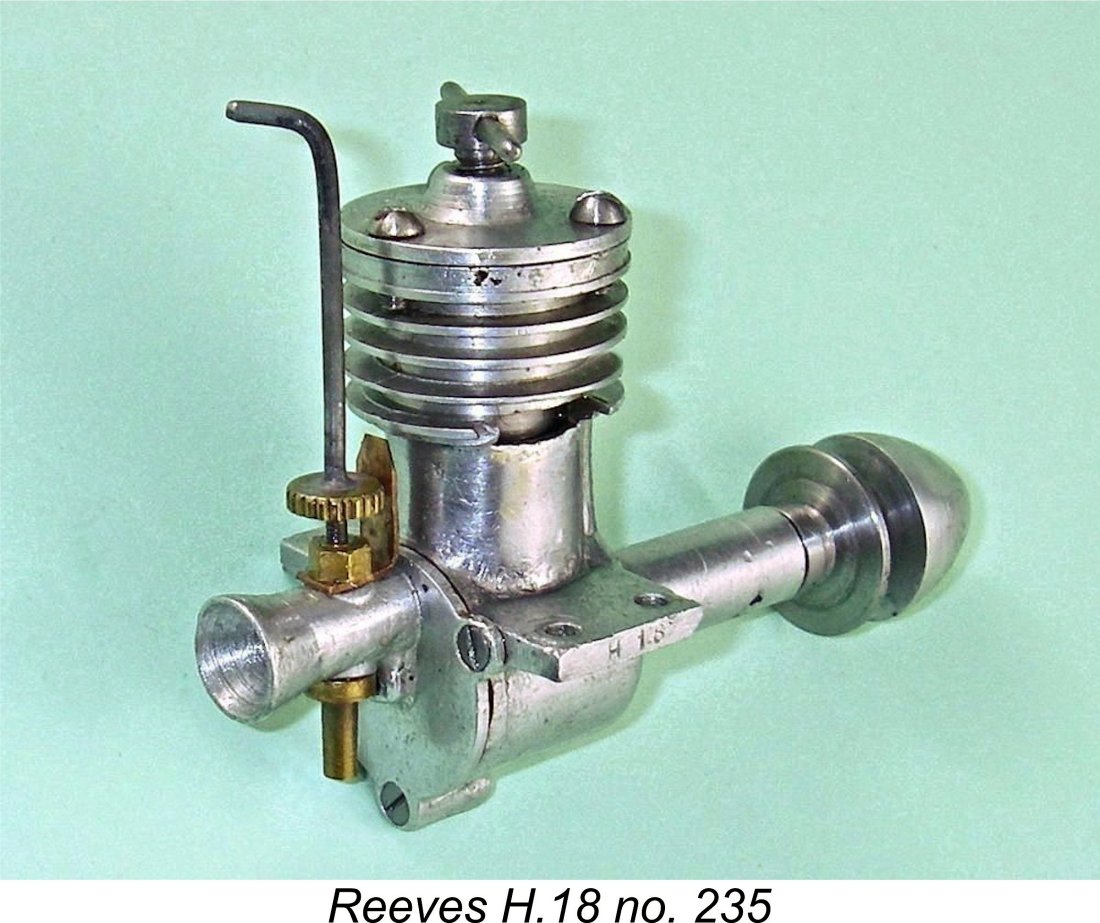
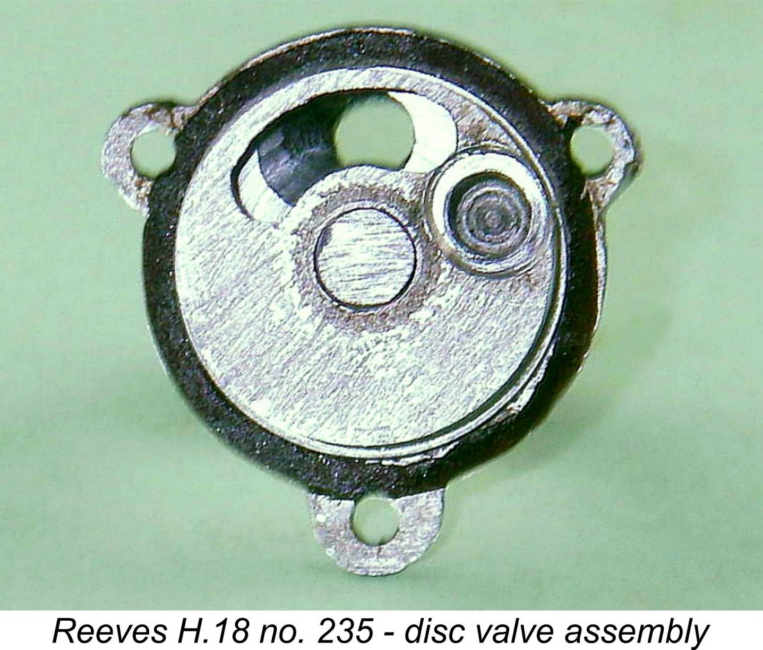 A conventional 1950-style disc valve of cast aluminium alloy is employed. This component is machined all over after casting - the sole evidence that it is cast is the kidney-shaped aperture for the actual gas entry, which retains the as-cast surface finish. The disc is conventionally driven by an extension of the crankpin which locates in a hole drilled in the disc. It is mounted on a steel spigot of generous diameter which is either pressed or threaded into the backplate - I didn't try to remove it to check. Since there is no retaining lip at the outer end of this spigot, the disc is maintained in contact with the backplate solely by the con-rod and (when the engine is running) by internal gas pressure within the crankcase. This is of course a perfectly sound approach - it was used on the
 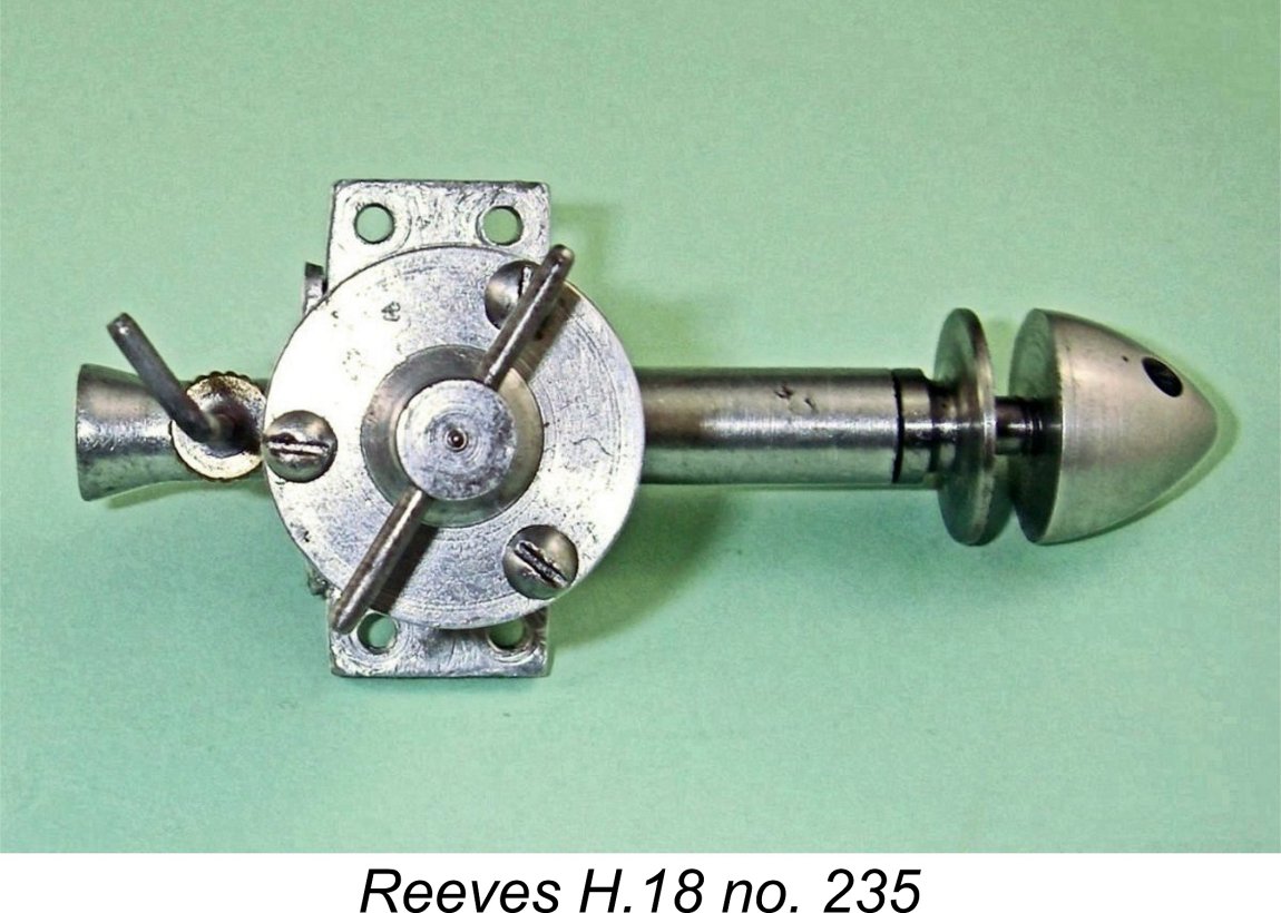 Another underlying design compromise is to be seen in the form of the location of the integrally-cast intake. This is centrally positioned at the top of the casting rather than being displaced somewhat in the direction of rotation as in the more usual case. The problem with the location adopted in the Reeves H.18 is that, even with the drive hole in the disc located as closely as possible to the trailing end of the disc aperture, it is not readily possible to delay the closure of the disc valve sufficiently to incorporate an adequate dwell period during which the intake remains open at and around top dead centre. In fact, with a kidney-shaped disc aperture and a round intake bore as employed here, the intake will actually close before top dead centre unless additional measures are taken - not a good situation from a gas flow standpoint!
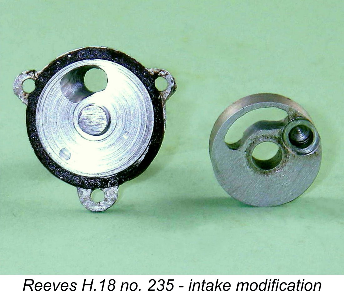 On my illustrated engine number 235, a considerable amount of careful hand work has been done to create a wedge-shaped cavity which extends the intake register opening in the direction of rotation and thus delays the closure of the system. This has the effect of postponing the closure until past top dead centre. The size of this hand-made cavity is about as large as the casting dimensions will permit without risk of breakthrough, but even so the closure delay past top dead centre is quite small - only around 15 degrees or so. Still, it's far better than no delay at all or even worse, having the system close before top dead centre as it otherwise would!
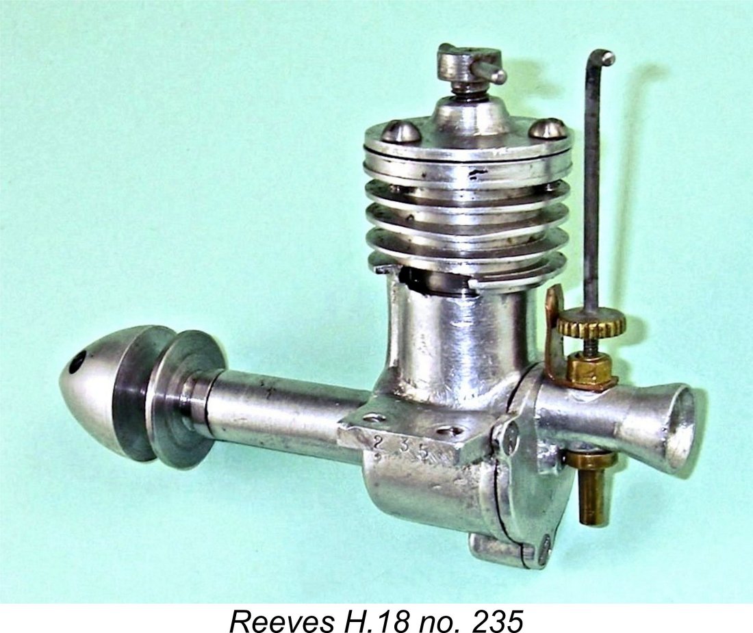 The integrally-cast intake venturi has a measured bore of 0.201 in. It is equipped with a conventional spraybar having two jet apertures, one on each side. The spraybar is internally threaded 8BA to accommodate an externally-threaded needle. Tension is provided by a single-leaf spring clip of sheet bronze which bears against the edge of a serrated brass disc soldered to the needle. This is very positive in action. The long needle extends above the top of the cylinder, thus being very easy to reach as well as being well protected against crash damage.
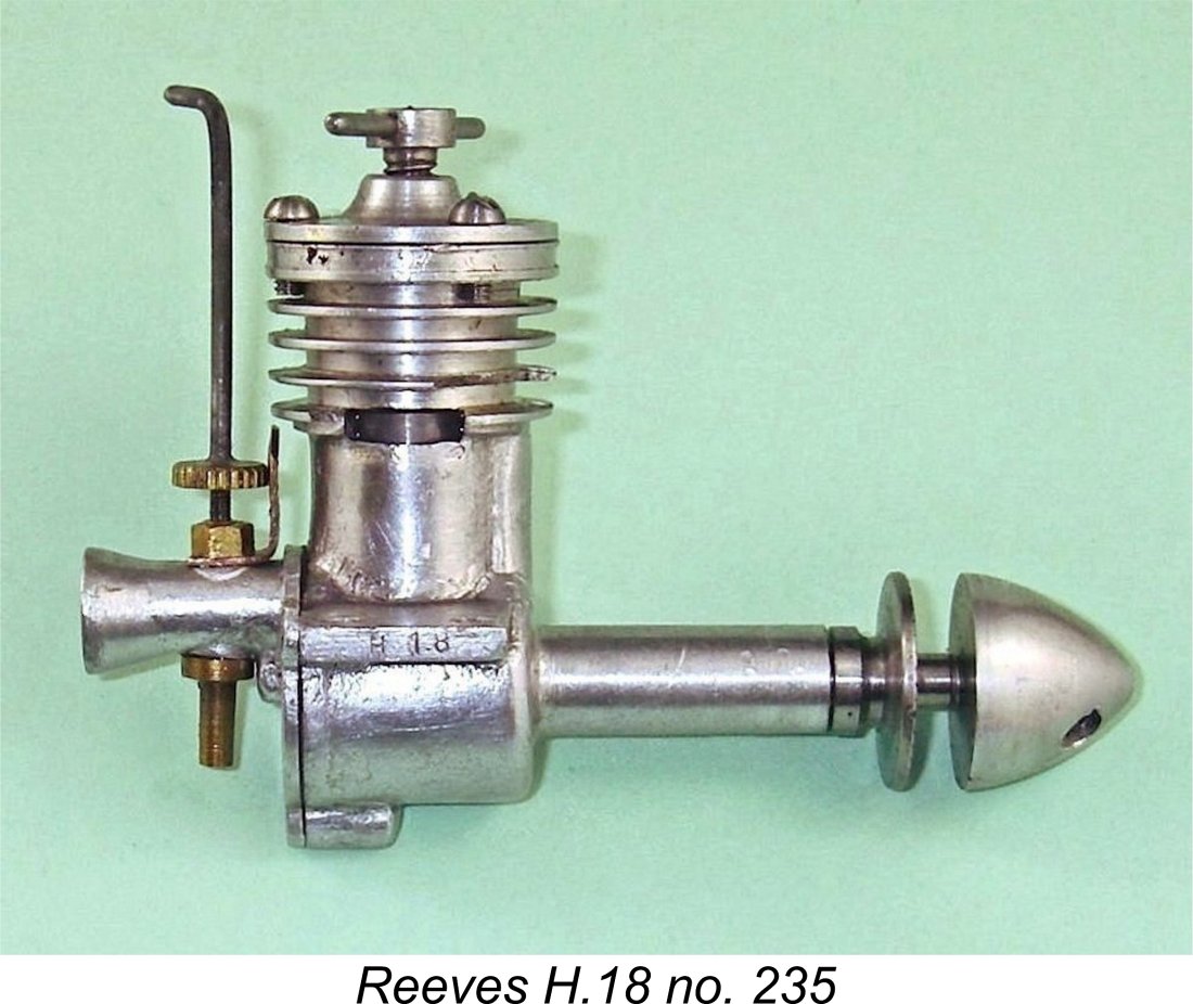
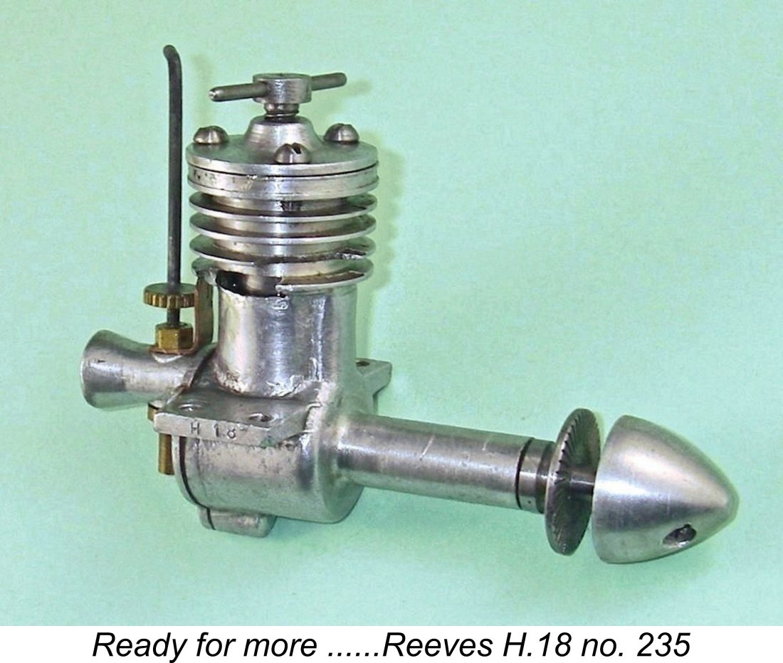
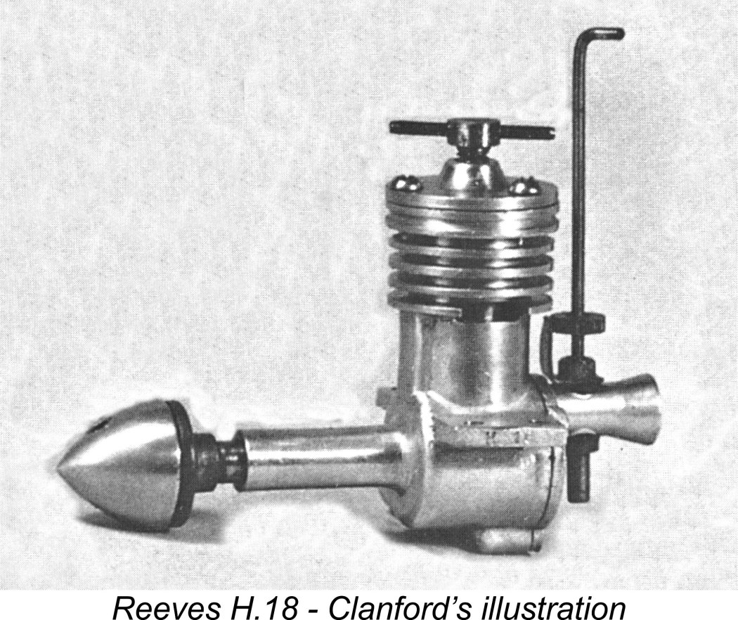 The majority of the engines were identified solely by having the sequence "H 18" stamped upon the outer end of one of the mounting lugs. Illustrated engine no. 235 displays this identification on the end of the right-hand lug (facing forward), as did the example tested by Lawrence Sparey (see following section). However, the one illustrated in Mike Clanford's useful but often unreliable
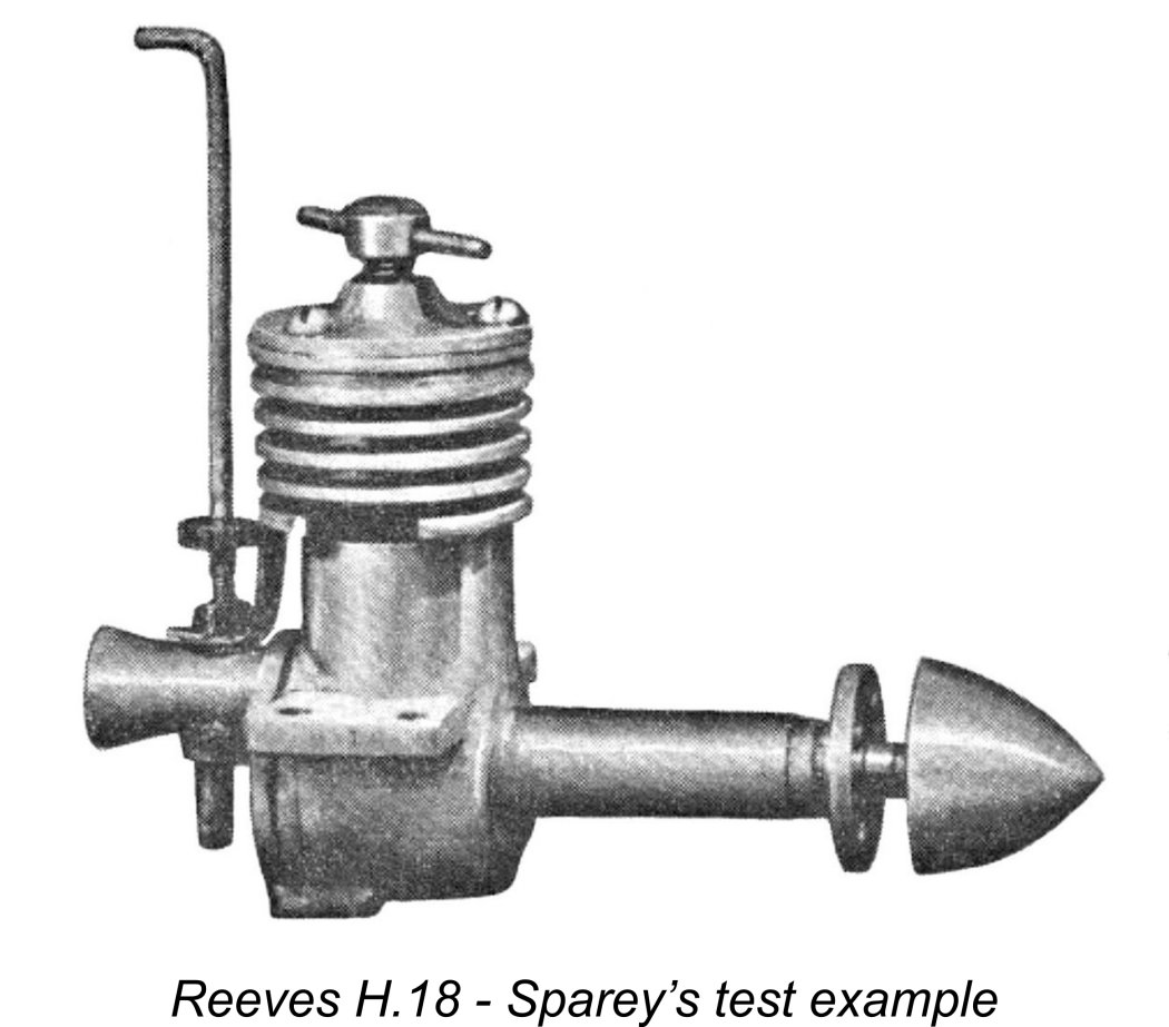
 One matter that received attention prior to the re-test was that problematic needle valve taper. During the first series of tests in late 2010, the needle valve had proved to be somewhat problematic. Contrary to Sparey's reported findings, I encountered some difficulty in establishing an optimal needle setting for a given load. This was no doubt due to the very coarse taper applied to the needle tip - a few clicks on the needle (a mere fraction of a turn) made a significant difference to the running. Once a setting was established, the needle held that setting firmly, but getting to the optimum point was not as easy as it would have been with a finer taper. Accordingly, prior to running the new series of tests I re-ground the end of the needle to a considerably finer taper.
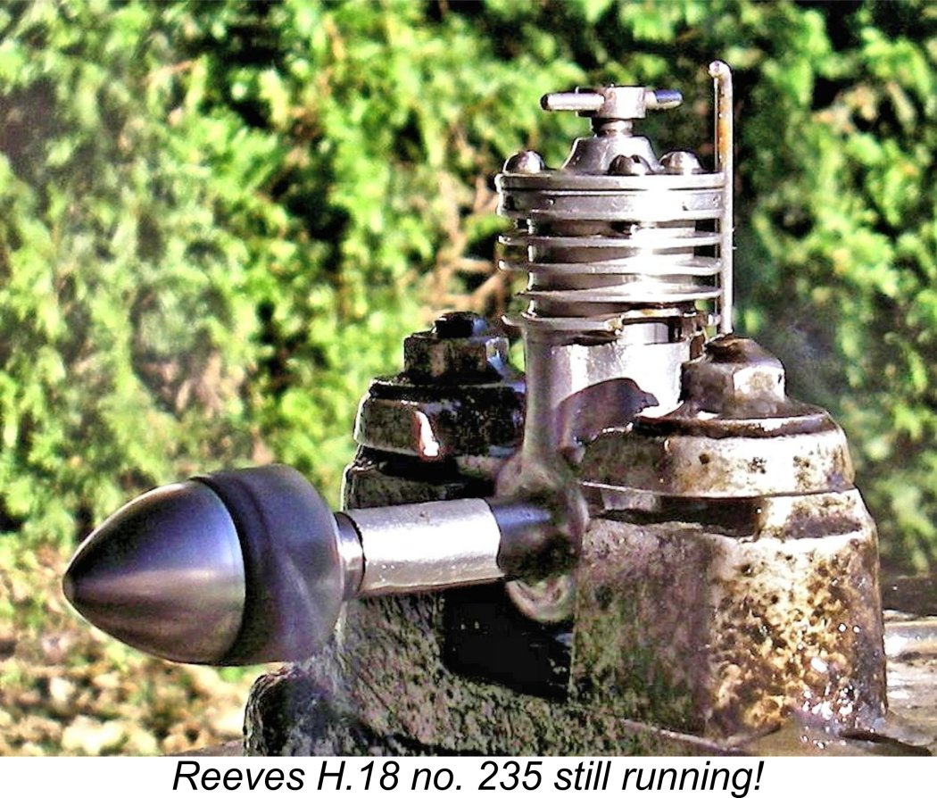 Once the engine was running, I quickly learned a few things about its control characteristics. The contra piston was just about perfectly fitted for a steel item - a bit on the loose side when cold but perfectly fitted for adjustment when hot - the common problem with a steel contra piston of freezing in the hot bore was not apparent at all, yet the engine held its compression settings firmly. Response to the compression control was quite lively, due no doubt to the relatively coarse 24 tpi thread used on the compression screw. Despite this, the optimum setting was easily established.
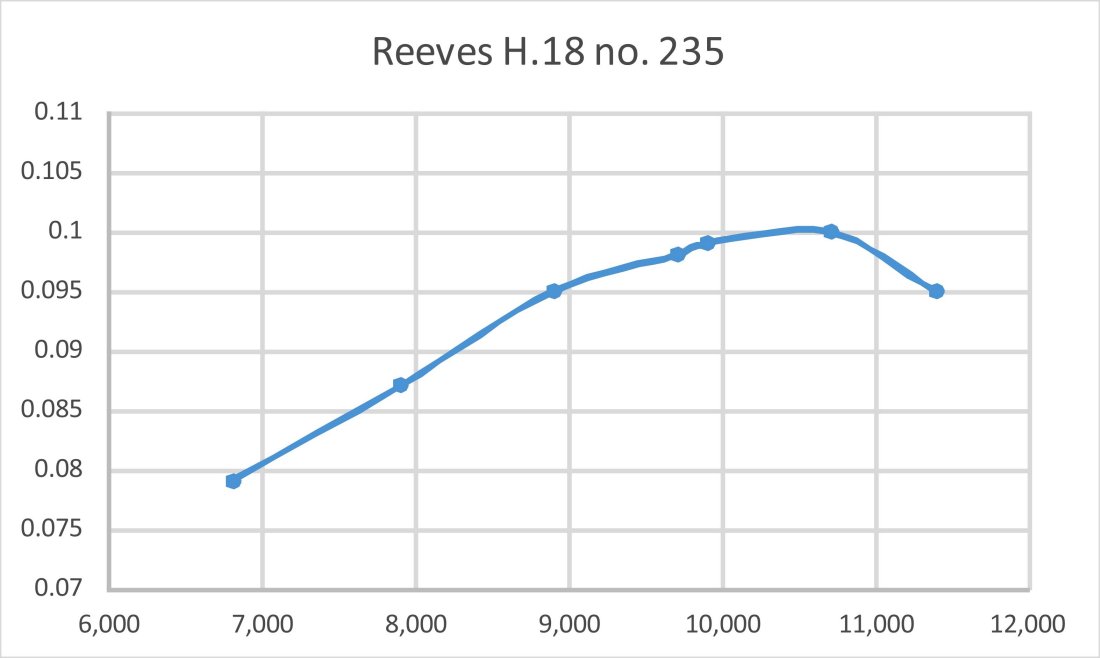
 The engine completed this latest test session with no problems and seemed willing to keep on running as long as required. Overall, I found it to be a more than acceptable "sports" performer by the standards of its day. The two features that I would have recommended changing are the unbraced main bearing and the taper on the needle. I could do something about the latter but there’s nothing to be done about that flimsy-looking bearing …………..
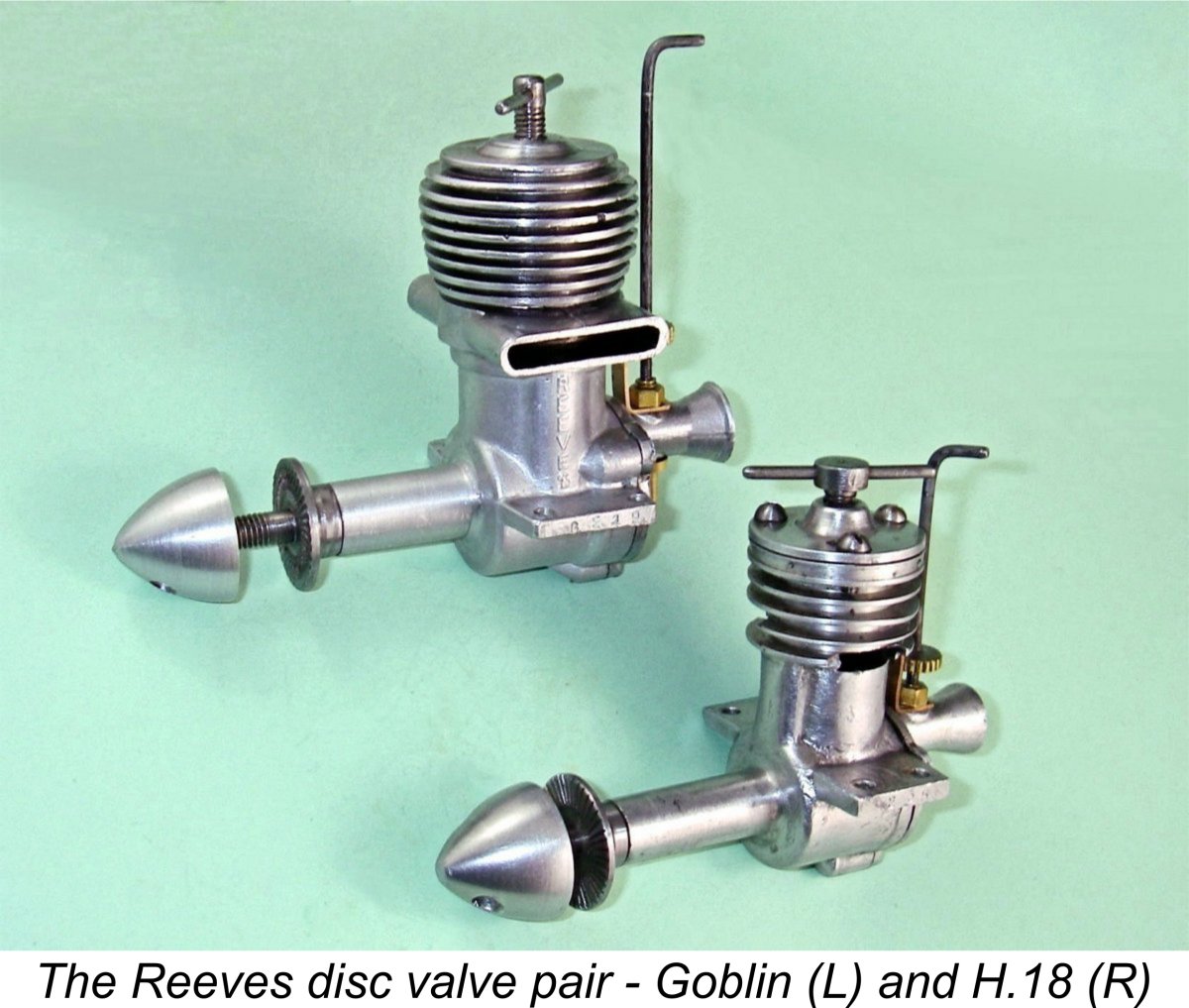 By April 1952 the hints dropped by Reeves had become reality in the form of the 2.5 cc Goblin diesel, another plain-bearing disc-valve model which evidently replaced the H.18 while retaining many of its design features. Unfortunately, the Goblin got off to the worst possible start by failing to complete its test in the hands of the resident "Model Aircraft" tester, almost certainly
 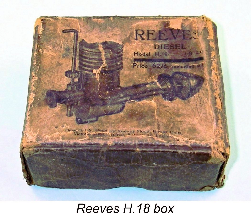 This was the last that was to be heard of the Reeves model engine line. A sad end to what had clearly been a very sincere effort on the part of a skilled model engineer to turn his passion to commercial account.
 I've noted that the H.18 appears to have remained in production for the better part of two years. There's no way of knowing for sure how many were produced during that period, but the rarity of the engine today suggests that the number can't have been that high. I'd need more serial numbers to get a better handle on this figure. In the absence of such data I can only say that the engine's present-day rarity indicates either that many of them were damaged in service (that seemingly vulnerable main bearing?) and subsequently discarded, or that there weren't that many of them made in the first place. Perhaps it was a combination of both.
| |