
|
|
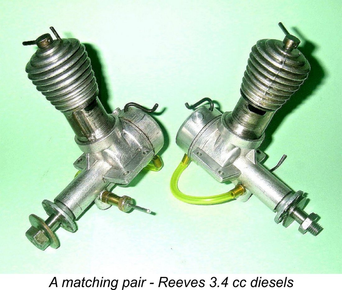
Shropshire Slogger - the Reeves 3.4 cc Diesel
In a previous article on this website I’ve covered the initial product of the Reeves venture - the excellent Reeves 6 cc spark ignition unit which was manufactured on a small scale artisan basis in two distinct variants during the years 1946 and 1947 prior to the rise of the model diesel in British aeromodelling and Reeves’ consequent early 1948 switch from spark to compression ignition. In another earlier article which appeared on the late Ron Chernich’s fascinating “Model Engine News” (MEN) website in June 2010, I also covered Reeves’ first diesel, the 3.4 cc model which forms my central subject here. Sadly, my mate Ron left us in early 2014 without sharing the access codes for his heavily-encrypted site. Because no maintenance has since been possible, the now-frozen MEN site is slowly but perceptibly deteriorating - an inevitable process which can have only one ending in the long run. I was unwilling to risk the loss of the information so painstakingly gathered on the Reeves 3.4 cc diesel, hence the article’s re-publication here. My justification for indulging in another masochistic exercise in the review of scantily documented but fascinating old model engines is that interest will only be sustained and the engines' long-term preservation encouraged after all of us old retreads are gone if their history is documented. No-one's going to collect or even take an interest in a class of items about which there's little or no recorded history - who would collect stamps if it wasn’t for the catalogues?!? Recording the history of model engine manufacturing will never be any easier than it is now since the window of opportunity for the recovery of any first-hand information about these more obscure ranges from people who were "there" is now all but closed. If it isn’t done now, it may never get done at all. As always in these cases in which little information appears on the record, I’m painfully aware of the fact that I’m only able to present the bare outlines of the story at best. If any reader knows something that I don't or experiences a stirring of an old memory upon reading my efforts, please get in touch and share what you know while the opportunity exists! All contributions openly and gratefully acknowledged, and the more the merrier. Since the Reeves engines were never made or circulated in large numbers, they are comparatively rare today. I looked for years before acquiring my first example of a product from this manufacturer - a near-mint example of the 3.4 cc diesel model which forms my main subject here. I’m one of the lucky ones - others are still looking. To underscore my good fortune, I subsequently had a second but less perfect example more or less dropped into my lap! My joy was somewhat tempered by the fact that it was a duplicate of the one that I already had, albeit incomplete. Still, this did confer the great advantage that I was able to replicate the missing parts very exactly using my all-original example as the prototype. Another Reeves faithfully restored - never a bad thing! Being in possession of two examples of the Reeves 3.4 cc diesel, I was placed in an ideal position to subject this very rare engine to a searching examination both in the shop and on the test bench and to share the results. Indeed, I considered myself to be under an obligation to do so. However, before I get to that, I should summarize what I know about the history of the Reeves model engine range in general. A Summary of the Reeves Range
No street address was ever given for either location, so it is impossible today to identify the former sites with any precision. In any case, the town has changed considerably since the war and the two sites have almost certainly been re-developed in consequence.
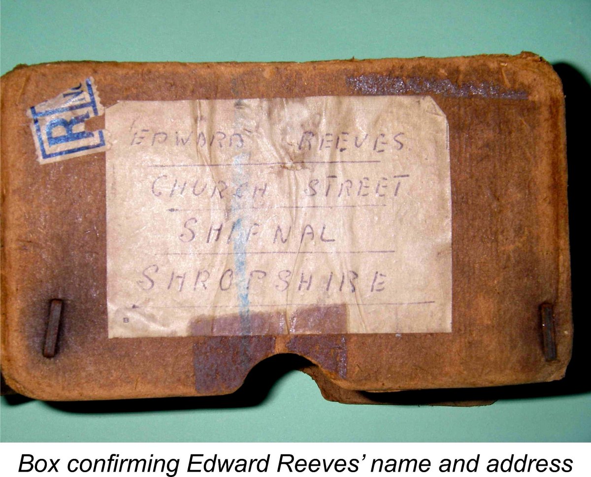
As far as I've been able to discover, the first Reeves advertisement appeared in the "Trade" section of the Classified Advertisement feature in the June 1946 issue of "Aeromodeller" magazine as reproduced at the left. This advertisement offered castings, blueprints and pre-machined components for a crankshaft front rotary valve (FRV) spark ignition engine which was available in both 5 cc and 6 cc displacements. A limited number of completed and tested engines were also reportedly available to first-comers. A 10 cc model was said to be in preparation, but there's currently no evidence that this design ever materialized. The initial advertisement was repeated with minor variations in subsequent issues of "Aeromodeller". These advertisements were placed in the name of E. Reeves, Model and Precision Engineers at the Church Street address. All that is known of this individual is that his name was Edward Reeves, as confirmed by the address on a surviving box which was used to return a 6 cc petrol engine to the maker for service in 1947. The date is confirmed by a piece of newspaper dated July 4th, 1947 which was used to line the box and is The manufacturer's initial address was simply given as Church Street in Shifnal. No street address was used, presumably because (in typical British small-town fashion) Edward Reeves was sufficiently well known as a resident of Church Street to ensure correct delivery without a number. Based upon the adresses given in Reeves' advertising, the move to nearby Victoria Road must have come in the latter half of 1948, some time after the company name change to Reeves Model Power units as reflected by the RMPU marking on the castings for the subject Reeves 3.4 cc model of that year. Like the majority of the small post-war British model engine manufacturing firms having a similar genesis, the Reeves company appears never to have expanded beyond its small-scale beginnings. Small-scale grass-roots manufacturing concerns of this type generally followed one of three routes - one, they grew by merging with a competitor (for example, Allbon merging with Davies-Charlton Ltd.; two, they established themselves in a competition market niche based on performance and quality along with the ability to charge accordingly (like Oliver and ETA); or three (and most commonly), they faded relatively quickly from the scene or moved on to other work. Edward Reeves never took advantage of the first possibility, and the second possibility was precluded by the fact that his products were never targeted towards the "performance" market, being very much in the nature of low-key sports engines. Despite this, Reeves Model Power Units actually ended up lasting longer than most of the other small-scale independents, staying the course for over 6 years. Despite advertising nationally from time to time in the British modelling media, Reeves never achieved the production volumes or distribution network which would have been required to establish a real presence on the national scene and thus compete with the larger contemporary volume manufacturers such as International Model Aircraft (FROG), Allbon/Davies-Charlton, Aerol Engineering (Elfin), Mills Brothers and E.D.. Consequently, the range always remained on the fringes, never attracting much attention from contemporary commentators. Even in their hey-day, such as it was, the Reeves engines constituted something of a "cult" range.
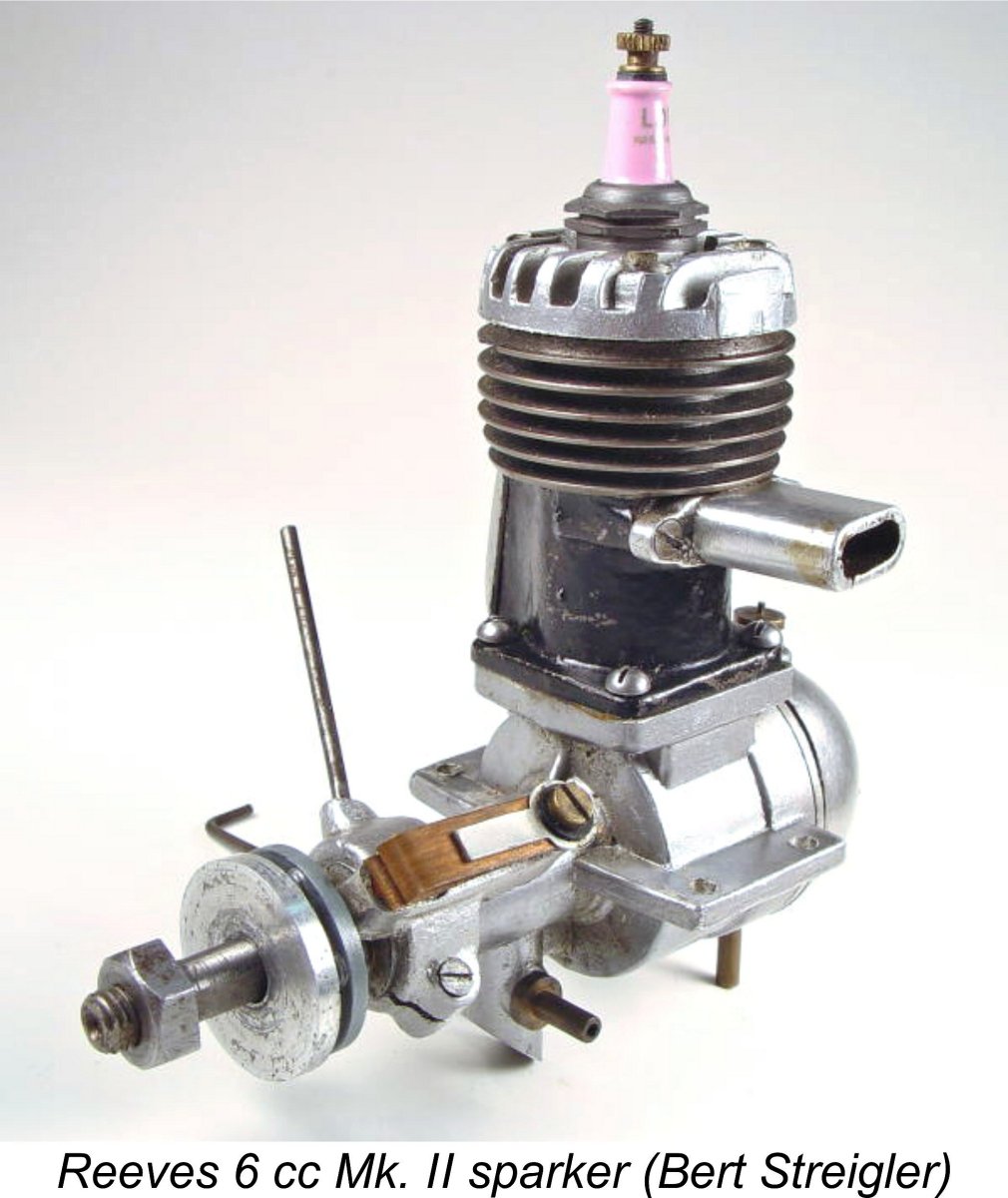
Distinguishing features of the 6 cc model included the updraft intake beneath the main bearing, the tall cast iron cylinder with integrally-machined cooling fins and the bolt-on bypass passage cover and exhaust stack. In his October 1952 test report on the later Reeves Goblin diesel, Peter Chinn recalled this model from his personal experience as "a sound and likeable spark ignition engine". My own hands-on experience bears out this characterization completely. As with all Reeves engines, the emphasis in this design was on internal fits rather than external finish. Consequently, despite their somewhat utilitarian appearance the engines quickly acquired a solid reputation for being well-made and dependable - Chinn's evaluation was typical. Reeves were to maintain this "care where it counts" philosophy throughout the production life of the range.
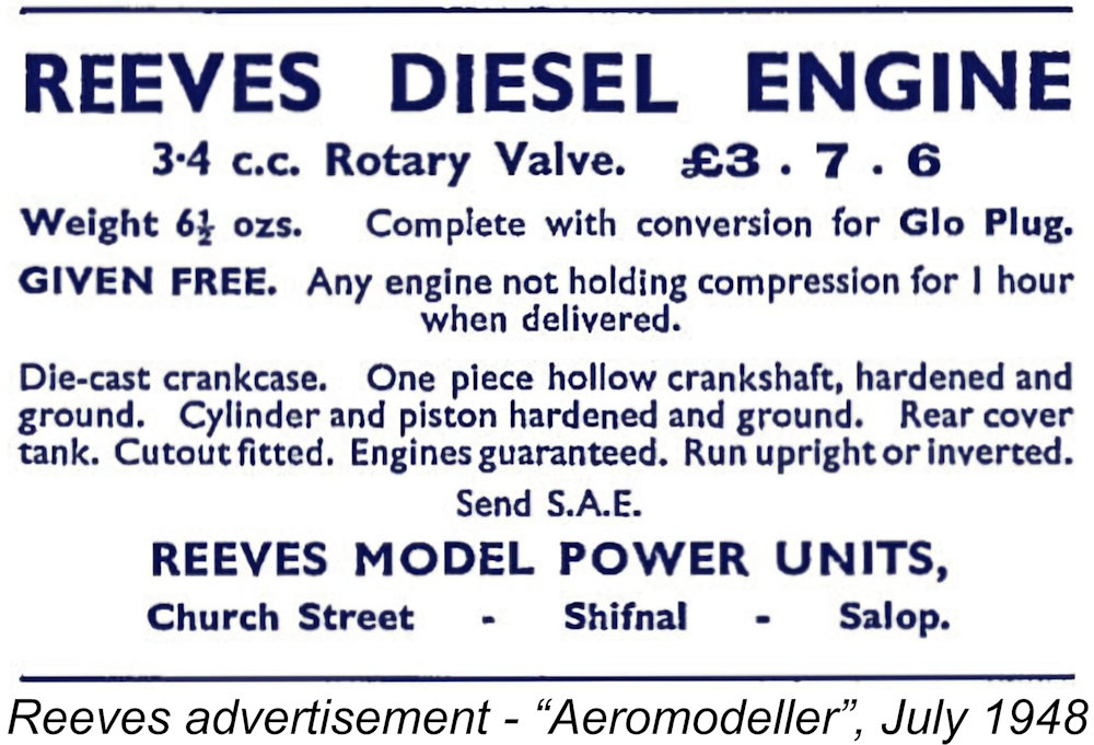
Although production of ready-to-run examples of the spark-ignition version of the Reeves 6 cc model seems to have ended at this point, the engine continued to be offered in casting form to the model engineering community until at least December 1948, as witness the advertisement from that month which is reproduced above at the right. There is persuasive evidence to suggest that a few examples were constructed in glow-plug form during 1948, either by Reeves himself or by one or two of his casting-set customers. An incomplete and severely battered example of such a variant was offered some years ago on eBay. Although the engine was very incomplete, it’s an indisputable Meanwhile, some greatly appreciated research by my friend and colleague Gordon Beeby of Australia has confirmed that Edward Reeves had definitely entered the diesel market as of February 1948, when his placement in the Classified Advertisement section of "Aeromodeller" included an offer of both complete examples of a 3.5 cc diesel and castings for the same. Similar classified advertisements followed in subsequent months. By July of 1948, Reeves had abandoned the Classifieds in favour of placing stand-alone advertisements alongside those of other companies. By this time, the displacement of the Reeves diesel was being cited as 3.4 cc, with both castings and complete ready-to-run engines continuing to be offered. Most intriguingly, later advertisements like that reproduced earlier stated that the castings were suitable for construction in displacements It appears that Reeves had some limited success in promoting the wider geographic distribution of his engine. The Reeves 3.4 cc diesel was listed by Arthur Mullett of Brighton in September 1948 and by The Model Stadium of North London in December 1948. However, those are the only dealer advertisements for the engine that Gordon Beeby was able to find. The Reeves 3.4 cc diesel had a broadly similar layout to its spark-ignition predecessor, with a tall cylinder and FRV induction through an updraft carburettor. However, the bolt-on bypass cover had gone, being replaced by a soldered-on sheet metal component. In addition, the integrally-machined cooling fins had been supplanted by a conventional screw-on cooling jacket machined from a light alloy casting. The cylinder was now made of steel instead of cast iron.
The Reeves 3.4 cc diesel was a dependable if unspectacular sports performer by the standards of its day. It was quite successful in the sense that Edward Reeves was evidently able to sell all of his relatively small production. The engine was mentioned in quite favourable terms by Col. C. E. Bowden in the 1949 second edition of his book “Diesel Model Engines”, which can't have hurt the cause. It was also included in the technical data tables which formed appendices to Ron Warring's 1949 book “Miniature Aero Motors”. The Reeves 3.4 cc model was still being advertised in late 1949 - it was featured in the Reeves advertisement in the November 1949 issue of "Aeromodeller" magazine, albeit by now with no mention of casting sets being available. An advertisement featuring the 3.4 cc diesel also appeared in the 1949 “Aeromodeller Annual” in which the price of the engine was quoted as a quite reasonable £3 7s 6d (£3.38). In this advertisement, castings were said to be available as well, and The quoted price apparently included the provision of a glow-plug conversion kit - a not uncommon practise among British manufacturers of the day. The attached image kindly provided by Bob Parry shows that the conversion involved the replacement of the contra piston with a centrally-threaded carrier for the glow plug. This was secured in place by a modified screw-on cooling jacket.
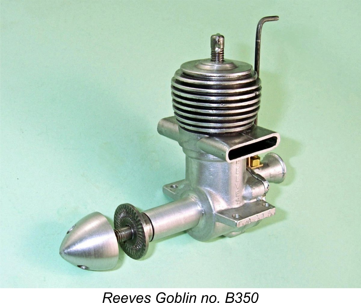
While still focusing on the 3.4 cc model, Reeves' September 1949 "Aeromodeller" advertisement announced the impending appearance of an entirely new 1.8 cc diesel unit. It seems clear that this was intended to be a replacement for the 3.4 cc design. The appearance of this unit was somewhat delayed, but it finally made its debut in the Reeves advertisement of January 1950. There was no further mention of the old 3.4 cc offering. The replacement model, designated the Reeves H.18, The H.18 remained in production for some time, still being advertised in “Aeromodeller” in November of 1951. However, by January of 1952 the company was no longer advertising a specific model but was instead hinting at new models to come. By April 1952, these hints had become reality in the form of the 2.5 cc Goblin diesel, a plain-bearing disc-valve model once again which evidently replaced the H.18. Unfortunately, the Goblin got off to the worst possible start by failing to complete its test in the hands of the resident “Model Aircraft” tester, almost certainly Peter Chinn. As noted in the published test report Although Chinn exercised his usual professional restraint, this report must have done much to seal the fate of the engine in the marketplace. You had to look hard to find a Reeves engine to buy at the best of times, and it would appear that after reading this test report people stopped looking. This was a pity, because the Goblin was an interesting design which was a quite attractive unit in many ways. The fact that a limited number of them still survive intact today indicates that they didn't all suffer the fate of Chinn's example - indeed, Chinn himself was of the opinion that he had simply got a flawed example of the engine since he felt that the basic design seemed sturdy enough. The engine's light weight of only 4.1 ounces was a strong point in its favour, while the partial power curve obtained by Chinn prior to the crankshaft failure implied a peak of around 0.17 BHP at 11,000 rpm, a quite acceptable figure for a lightweight plain-bearing 2.5 cc diesel in 1952. In his 1977 “Collector's Guide to Model Aero Engines”, O. F. W. Fisher recalled using the Goblin to power a three-engined helicopter! Seemingly, he at least got the engines to work OK! A full hands-on latter-day review of the Goblin appears elsewhere on this website. This test was conducted on an example which had been rebuilt with a stronger shaft by Dean Clarke of New Zealand's Cre8tionworx Engineering. It confirmed that the Goblin could have been a very useful engine - the rebuilt engine was an excellent runner which developed around 0.221 BHP @ 11,200 RPM, a perfectly acceptable performance for a lightweight plain-bearing 2.5 cc diesel in 1952.
There has been speculation in the past that there might have been some kind of connection between Reeves Model Power Units and the well-known model engineering supply firm of A. J. Reeves & Co. (now Reeves 2000), who started just after WW2 at Moseley Road in Birmingham at more or less the same time as Reeves Model Power Units became established in Shifnal. However, no less an authority than the late Ron Moulton assured me from his own first-hand knowledge that no such connection existed. The present owners of the Reeves model engineering business have confirmed this. Having reviewed a capsule history of the activities of the Reeves model engine manufacturing concern during its 6-year existence, let's commence our detailed look at a sample of their work in the form of the 3.4 cc model with which Edward Reeves entered the model diesel field in early 1948. The Reeves 3.4 cc Diesel in the Modelling Media
"The "Reeves" 3.4 cc has a crankshaft rotary valve, and is suitable for planes from 2 ft. 6 in. span control line to medium size free flight. The bore is 0.570 in., stroke 0.760 in., weight approx. 6½ oz. The cut out is of the positive valve type, and the tank is located at the rear of the crankcase. This motor has a good speed range. See Fig. 44." Figure 44 provided a good general view of the engine, with the caption: "The Reeves diesel of 3.4 cc has a rotary crankshaft valve and a good speed range from 2,000 to 7,000 rpm." The technical tables in Ron Warring's “Miniature Aero Motors” confirm the above measurements in every respect and provide details of the engine's material specification which are again confirmed by direct observation. However, there are a few readily apparent anomalies! The displacement given by Warring is 3.4 cc (0.208 cuin.), exactly as indicated in the engine's name, and Warring also confirms the bore and stroke figures quoted by Col. Bowden. My own direct measurements of two examples confirm those bore and stroke figures almost exactly, and I also come up with a weight of precisely 6.5 ounces, including the tank. So far so good, but my pesky calculator keeps on converting those confirmed bore and stroke figures of 0.570 in. (14.48 mm) and 0.760 in. (19.30 mm) into an actual displacement of 3.18 cc (0.194 cuin.) rather than the 3.4 cc of the engine's name! I really have no explanation for this - I can only say that both of my examples check out more or less identically at the stated bore and stroke figures. So it appears that we are dealing here with an engine having a true displacement of only 3.18 cc, whatever the makers may have claimed! The other seeming anomaly in Warring's table centres upon the airscrew recommendations. Warring generally used manufacturer's recommendations as a guide, and it's possible that this is what he was doing here. He recorded 13x6 as the recommended airscrew for free flight and 11x8 as the recommended control-line prop. Both recommended sizes strongly imply that high operating speeds were not envisioned! Based on my own tests (see below), the suggested control-line prop isn't too far off base but the cited free flight size pulls the engine's speed way down below its optimum operating range. I'll comment further in the test section of this article. So much for the treatment of the engine in the contemporary modelling media. The only later comment that I can find that has any relevance is O. F. W. Fisher's note on page 40 of his 1977 “Collector's Guide to Model Aero Engines” to the effect that he had used the Reeves 3.4 cc engine (incorrectly identified as the Reeves 3.5 cc) in both a 5 foot span sports free-flight model and the prototype Eclipse Mk. II twin-engined control line stunt model. Clearly, Fisher had found the engine to be perfectly satisfactory in actual service. He also noted that his example too passed the Reeves "one hour compression test"! I suspect that most of them did. Let's now take a close look at the engine for ourselves to see if we can learn anything more. The Reeves 3.4 cc Diesel - Description
However, when one actually gets to grips with the engine and starts turning it over, these initial impressions immediately cease to hold centre stage. The Reeves is outstandingly well-fitted throughout - neither of my two examples exhibits any detectable trace of play anywhere in the power train, and compression seal is absolutely perfect without there being the slightest trace of binding at any point in the stroke. I can honestly say that I have never encountered better-fitted pistons in a lapped engine - the engines feel positively "silky" when turned over. When oiled, both of my examples easily pass the Reeves "1 hour compression test" after who knows how much running. The construction of the engine is about as simple as it could possibly be. No screws are used apart from the tank retaining screw - all major components are of the screw-in variety. The engine is built around a very solidly-proportioned gravity die-cast aluminium alloy crankcase. An internally-threaded recess at the top of this casting accommodates the base of the screw-in steel cylinder. A gasket is used to ensure a good seal at this point.
The steel cylinder is of basically tubular form, with two opposed exhaust ports of roughly oval shape. A ledge just above the exhaust ports locates the screw-on cast aluminium alloy cooling jacket. An internally-chamfered expansion is incorporated near the cylinder base, serving the dual purposes of carrying the external male assembly threads and providing for the inclusion of an annular internal channel inside the cylinder at its base. This channel surrounds the lower piston skirt at bottom dead centre and ensures access of transfer gas to the bypass passage regardless of the radial position in which the cylinder may end up when securely tightened.
The upper end of the bypass passage communicates with the cylinder through three drilled holes which together constitute the actual transfer ports. These three holes are located between the twin exhaust ports in such a position that they overlap the exhaust to a significant degree. They are drilled diametrically through the cylinder wall rather than being drilled at an upward angle, which might have helped to direct the incoming charge into the upper cylinder. As it is, the incoming gas is discharged more or less directly into the escape path of the exhaust gases. As a result, considerable losses of incoming mixture through the exhaust ports may be expected. At the top end, the contra piston is of hardened steel, which is a problematic choice of material in that a steel contra-piston has an aggravating tendency to stick in a steel bore when the engine warms up. The cooling jacket is another casting in aluminium alloy which is internally threaded and screws onto the threaded upper cylinder in conventional fashion. The single-armed compression screw is carried in this component, and the range of available compression settings is limited by the inclusion of a wire stop in the Looking now at the working components, the hardened steel piston is an extremely substantial item which displays no signs of any attempt to lighten it through appropriate machining operations. It communicates with the crankshaft through an equally substantial connecting rod made of bronze alloy. The gudgeon (wrist) pin is of 0.140 (9/64) in. diameter and is pressed into the piston bosses. The reciprocating components (piston, gudgeon pin, con-rod) together weigh all of 19 gm. (0.67 oz.)!! High revs need not apply!
The main bearing is relatively long - a good feature for stability and wearing qualities. A steel bushing is incorporated. The fit of the journal in this bushing is as close as the fits in the rest of the engine. Overall, I'd expect this motor to run forever as long as it was well handled and supplied with good fuel!
The screw-in aluminium alloy backplate is again machined from a casting. A gasket is used to ensure a good seal. The tank is a stamping from soft aluminium alloy. It is attached to the backplate with a single screw. The tank is unusually short, but the backplate recess adds considerably to its internal volume, providing a total capacity which is more than adequate for free flight purposes. The tank incorporates a threaded filler hole which is stopped with a vented screw-in plug - a somewhat unusual feature. The fuel supply spigot at the base is threaded into the material of the tank. However, the most individualistic feature of this tank is the cut-out! This is more easily illustrated than described - hopefully the attached composite image will suffice to clarify the design. In simple terms, a thick bent wire plunger enters the tank at the top. It carries an internal compression spring which acts to force it downwards. It is bent in the middle to clear the tank retaining screw. At its lower end it features a ground tapered point which engages with the inner end of the screw-in brass fuel supply spigot to which the fuel tubing is attached.
The solution is actually both simple and elegant. The outer end of the plunger is bent into a "hook" shape in such a way that when it is pulled up it can be swung around through 90 degrees in a clockwise direction to allow the end of the "hook" to rest on the top of the tank, keeping the plunger in its open position. To activate the cut-out, all that is required is to pull the outer tip of the "hook" towards the rear so that the end of the "hook" slips off the tank and the spring returns the plunger to its closed position. In a strictly mechanical sense, this arrangement works perfectly. It will be appreciated from the geometry of the situation that the action of swinging the "hook" off the tank to activate the cut-out causes the plunger to be pulled a little further out initially, an action which the system naturally resists. Consequently, the system remains in the "open" position very securely while the engine is running, showing no tendency to work towards the "shut" position due to vibration. Despite this, the word on the street regarding this unit is that it didn't work, plain and simple. How true is this condemnation? There's only one way to find out - let's set these engines up on the bench and give them a try! The Reeves 3.4 cc Diesel On Test
The first engine tested was my first example which was complete and original in all respects (at the left in the accompanying image). An issue which had to be addressed right away was the fuel supply. With the engine mounted in an upright configuration, the back tank necessarily provides gravity fuel feed. With the needle open for starting, the fuel simply drips continuously out of the intake without any getting into the engine. The tank appears to be intended for use with the engine inverted. To get around this, I resorted to the use of a separate tank which provided suction feed. Having dealt with this issue, I encountered another immediate problem - the contra piston was well and truly frozen in the bore! It seems that this had occurred with the engine at running settings, because I was actually able to get it started at the setting in which it was frozen. However, even after a few heat cycles the contra piston remained immobile, no matter what I did. So I put this one away for a future re-test after un-sticking the contra-piston in my home workshop. The other example which I had restored using replica components faithfully copied from its partner was far easier to manage and could be adjusted quite readily. Even so, it exhibited the previously-mentioned tendency for the steel contra-piston to freeze in the steel bore upon warming up. However, the contra-piston invariably freed up quite quickly after the engine had stopped. Hence, settings were always manageable, although it was occasionally necessary to stop the engine momentarily to make a needed correction.
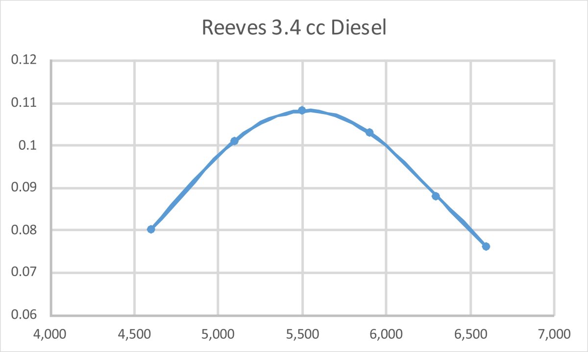
The other starting characteristic of the engine was one that is typical of engines fitted with updraft intakes when run in an upright position. Finger-choking is of little use with such engines - the fuel simply drips by gravity out of the intake rather than being absorbed by the engine. A prime is thus more or less essential for reliable starting. However, the fact that the engine seems to have excellent suction ensures that it picks up very quickly on a prime. I'd objectively rate the Reeves 3.4 as being very easy indeed to start once the settings have been established. In view of the problems with the first engine's contra-piston, I elected not to take any test figures on the initial session because the whole benefit of having two examples to test was the reduced possibility that a given test engine was either a "good" or "bad" one - there's a lot of value in reproducibility of testing! I contented myself with giving both engines a little running time to settle themselves down. Even this amount of running was enough to indicate that the Reeves 3.4 cc diesel was no world-beater in performance terms! Low-speed torque rather than top end power were clearly its strong suit. Returning another day after sorting the problem of the sticky contra-piston in the first engine, I was in a position to test both units together. One of the two examples proved to be very slightly faster than the other on a given load, but the difference (only a matter of 100 rpm or so) was well within the expected range of variation between different examples of the same series-produced design with perhaps different amounts of running time. I therefore elected to report the results for the slightly faster example, with the caveat that both examples exhibited pretty much identical performance potential and handling characteristics. The engines both started equally easily and ran very steadily under all loads. The establishment of optimum settings for both the compression and needle valve proved to be quite easy since both controls were very effective without being unduly sensitive. The engines were relatively impervious to artificially-induced changes in the fuel tank level, indicating that suction was pretty good. Vibration levels were unquestionably on the high side, as one would expect given the very heavy reciprocating mass involved, but at the speeds of which the engine proved capable this did not represent a really major issue. The slightly better of the two engines managed to drag the 11x7 Zinger test prop around at a reasonably respectable rate (for a 3.2 cc engine) of 5,100 rpm and seemed quite happy doing so - running was remarkably steady and smooth. This is right in the middle of Col. Bowden's "good" speed range of 2,000 to 7,000 rpm. I tried an APC 12x6, which was turned at a rock-steady speed of 4,600 rpm. The engine was clearly quite happy at these very low speeds, and being a diesel the ignition timing can of course be set to accommodate such speeds with no excessive loads on the working parts. Being anxious to test the upper regions of Col. Bowden’s quoted range, I then proceeded to try a series of progressively lighter airscrews. The results obtained are summarized in the table below, with the BHP figures being those implied from known or derived power coefficients for the airscrews involved.
None of the tested props apart from the 12x6 and 11x7 bore any resemblance to those recommended in Warring's tables! And even the 10x4 didn't allow the engine to reach the 7,000 rpm upper limit noted by the good Colonel. I didn't feel inclined to test the engine past that point in any case given the vibration levels already being experienced plus the clear indications that power was falling off sharply above 6,000 rpm anyway. Although running remained absolutely smooth throughout, vibration above 6,000 rpm was now becoming quite noticeable, even in the test stand. My conclusion was that the engine peaks in the region of 5,500 rpm or so at around 0.108 BHP and that there's little point in pushing it much further. This is undeniably a rather dismal performance for a 3.2 cc engine, even in a 1948 context - a 2 cc K Kestrel tested at more or less the same time handily beat this power figure, albeit at a significantly higher speed. However, it's true that the Reeves delivers its power at a very usable speed for sport free-flight use, while the engine's docile handling characteristics and excellent flexibility might well have been viewed as useful assets in that context. The low power would have been far more of a limitation for control-line applications. As far as I can tell, the limiting factors are probably the high vibration levels resulting from the overweight reciprocating components, coupled with poor scavenging arising from the somewhat convoluted bypass arrangements and relatively inefficient transfer porting. As noted earlier, the diametrically-drilled holes provide little in the way of direction to the incoming transfer gas flow, and a fair proportion of the fuel mixture supplied seems to leave unburned via the exhaust ports - a well-trained nose can easily detect this while the engine is running. With these results in hand, the prop recommendation given by Warring for control-line use actually makes a certain amount of sense. An 11x8 prop would likely slow the engine to around 4,700 rpm or so on the ground but would probably approach the peak in the air. Using the time-honoured formula: Airspeed = RPM x Pitch (inches) 1320 we find that one might expect an airspeed of around 35 mph with the engine running just past its peak at 5,700 rpm on an 8 in. pitch prop. For my part, I'd be tempted to try something like a suitably-trimmed 10x10, which might get the airspeed up to somewhere in the neighbourhood of 44 mph. These speed figures may be a little on the low side - the above formula incorporates a 20% allowance for prop slippage, and the large props about which we're speaking here might do a little better than this. Prop efficiency tends to increase with size. All well and good, but the 13x6 recommended for free flight would unquestionably bring the engine to its knees. Based on my own testing, I'd probably opt for the recommended 11x8 for control line, or perhaps a 10x10 to get higher airspeed at these low revs. An 11x6 or 11x7 would likely be ideal for free flight. The suggested 13x6 would kill the engine for that purpose.
So - enter the cut-out!! Question is - does it work? I naturally took a close interest in this question, and the answer is that the cut-out works perfectly when the engine is running in a leaned-out condition - the engine stops in around one second every time. However, if the engine is set rich, activating the cut-out speeds it up by leaning the mixture, but doesn't always stop it. This suggests a) that the engine has pretty good suction and b) that that the seal between the plunger tip and the fuel orifice is perhaps less than perfect in the tested examples. I'd guess that this was probably typical. The problem with a cut-out of this nature is that its effectiveness is entirely dependent upon the closeness of the fit between the tapered end of the plunger and the opening of the fuel spigot. The tests that I undertook show that if that fit is even reasonably close, the cut-out works quite well enough for practical purposes. Furthermore, the fact that the fuel spigot can be unscrewed from the tank for attention means that any irregularities which might prevent a good seal between the plunger and the orifice can easily be corrected. A Further Variant
Graham advised that this was the only stack-equipped example of this engine that he had ever seen. It seems likely that this was a special-order modification and that very few engines were produced in this form. My sincere thanks to Graham for making us aware of this seemingly super-rare variant! Conclusion It's clear from the above discussion that we're talking here about an engine that is all about torque rather than horsepower. There's no doubt at all that it's an extremely well-made and dependable power unit which is very easy to handle and should give indefinite service in sports model applications. However, there was no way in which it could compete in either visual or performance terms with the new generation of 3.5 cc diesels such as the AMCO 3.5 and the E.D. Mk. IV which began appearing in 1949. Viewed in this context, its early departure was inevitable. Still, an interesting example of the work of our friend and kindred spirit Edward Reeves! I hope that you've enjoyed my attempt to draw the veil aside a little! ________________________________ Article © Adrian C. Duncan, Coquitlam, British Columbia, Canada First published on MEN June 2010 Re-published here May 2023
|
||
 Once more into the breach, dear friends! Yet again, I find myself taking as my subject a product of one of the more sparsely documented British model engine marques of the early post-WW2 era - the somewhat obscure Reeves 3.4 cc diesel from Shifnal in Shropshire.
 The Reeves model aero engines were manufactured on a relatively small scale in Shifnal, a small English town which lies in Shropshire a little to the south-east of Telford between Wolverhampton and Shrewsbury. The company initially traded under the name of E. Reeves, Model and Precision Engineers from an address on Church Street. By mid 1948 they were trading as Reeves Model Power Units, soon thereafter moving from Church Street to an address on Victoria Road, now part of the A464 and hence one of the main thoroughfares passing through the community. Both Church Street and Victoria Road appear on the attached map.
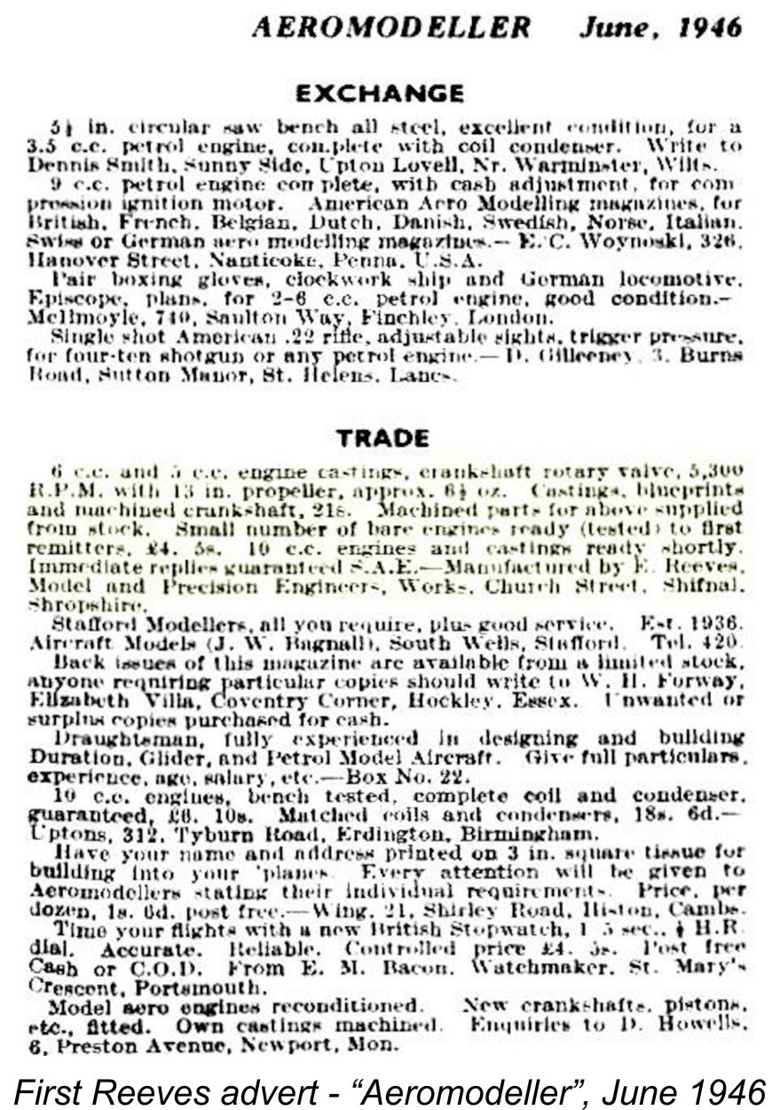
 The venture began in mid-1946 with the first of two successive variants of a 6 cc crankshaft front rotary valve (FRV)
 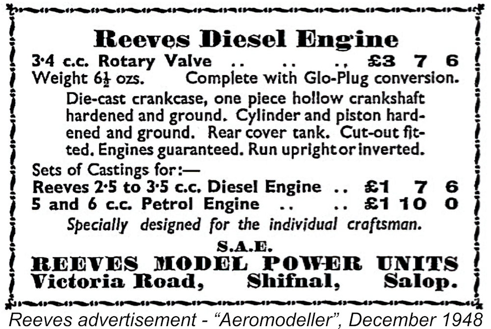 The successive variants of the Reeves 6 cc sparker enjoyed a twenty-month production run, selling steadily enough that the small workshop in which they were made was obviously kept quite sufficiently busy to justify continued production and further product development. However, by early 1948 the diesel engine was well and truly in the ascendant in Britain, while the appearance of the glow-plug in America had already heralded the beginning of the end for the spark ignition engine. Edward Reeves clearly recognized this, and it was in early 1948 that he took a significant step towards the future by ending production of the trusty 6 cc sparker in favour of his first diesel design, the 3.4 cc model which forms the main subject of this article.
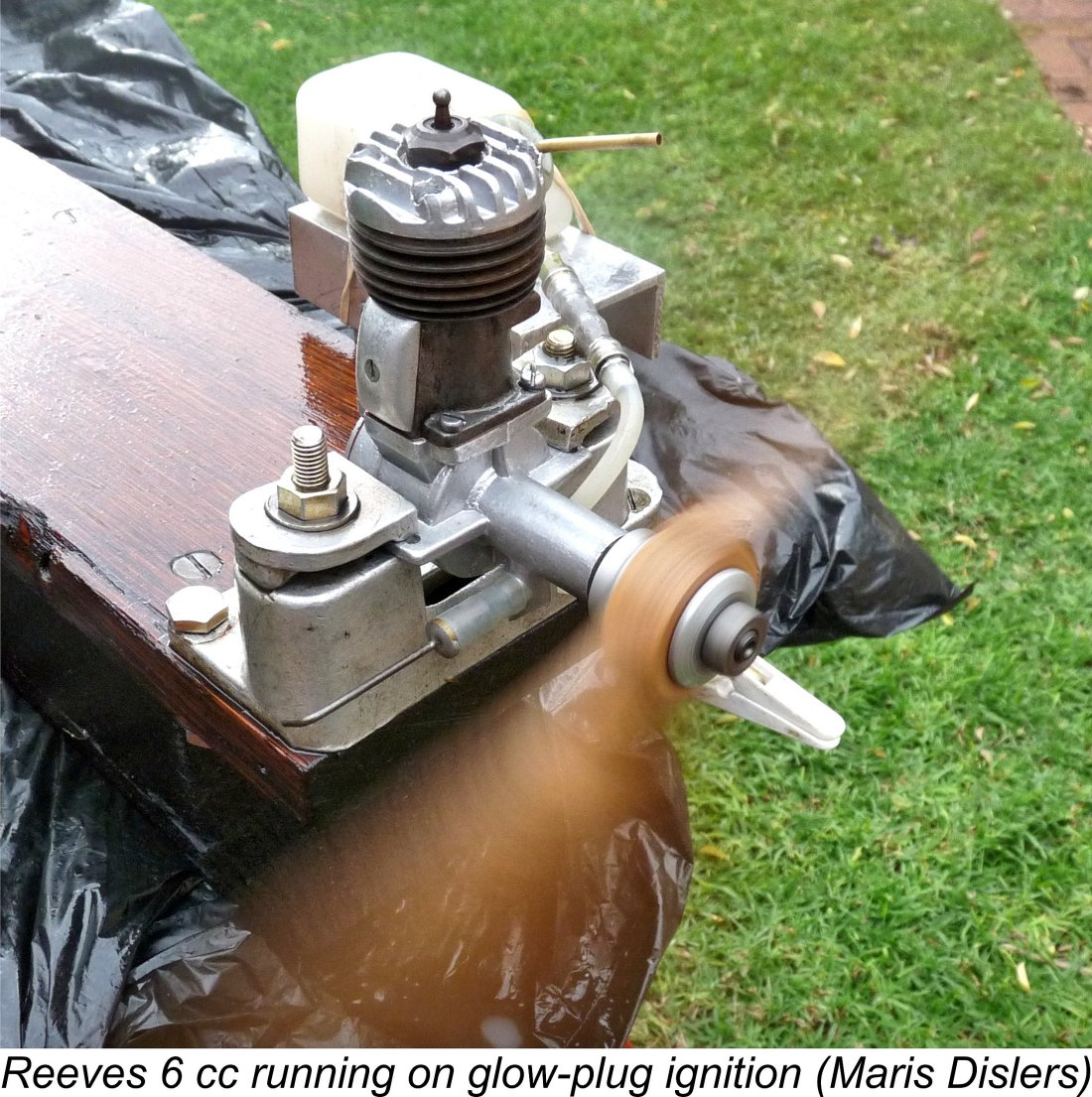
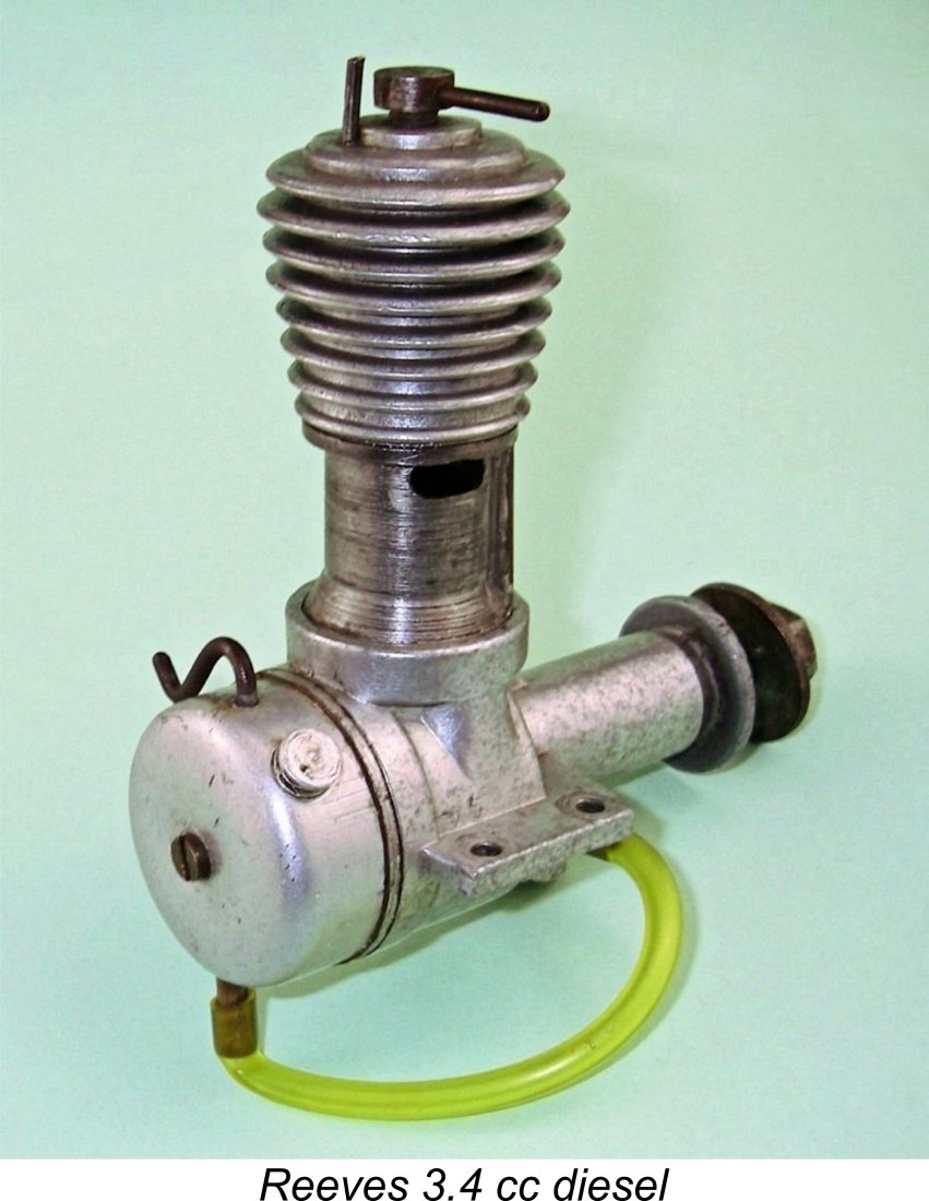
 As usual with Reeves, the appearance of the new diesel model was lacking in sophistication, with the initial visual impression being that it lay somewhere between the crude side of good and the good side of crude!! However, this impression was quickly dispelled when one handled an example - the internal fits and finishes were beyond reproach. Indeed, it was this model which was the subject of Reeves' remarkable guarantee to the effect that if an oiled example of one of these engines failed to hold its compression at top dead centre for a minimum of one hour, the buyer could retain it free of charge!! I can only report that both of my examples still pass this test today, even after an unknown amount of running.
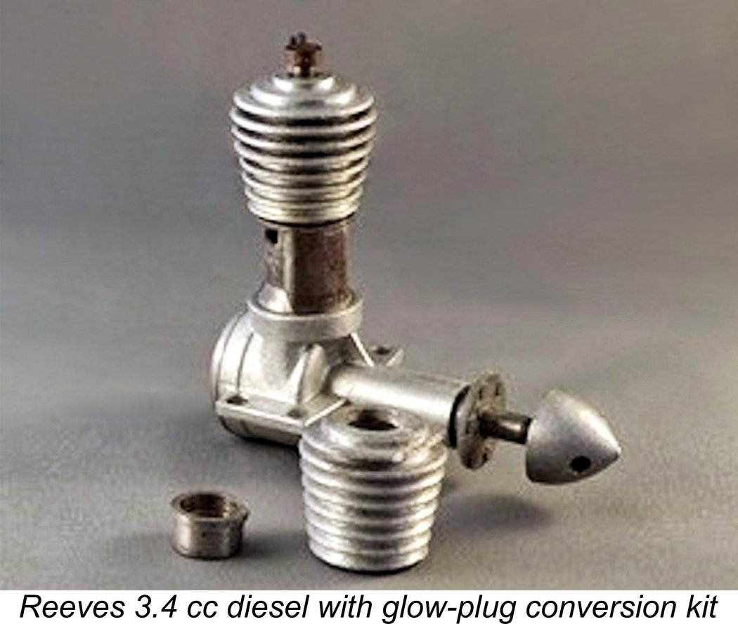
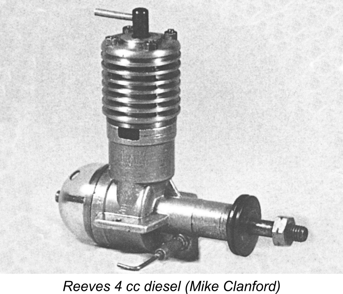 One other model from this period about which we do know a little was a 4 cc version of the 3.4 which was generally quite similar but was "prettied up" a little and utilized a bolt-on cylinder assembly in place of the former screw-in system. This very rare engine cannot have been made in large numbers - it never made an appearance in Reeves' advertising and is very seldom encountered today, although a few examples do exist. Production of the Reeves 3.4 cc and 4 cc models appears to have ended at some point in late 1949.
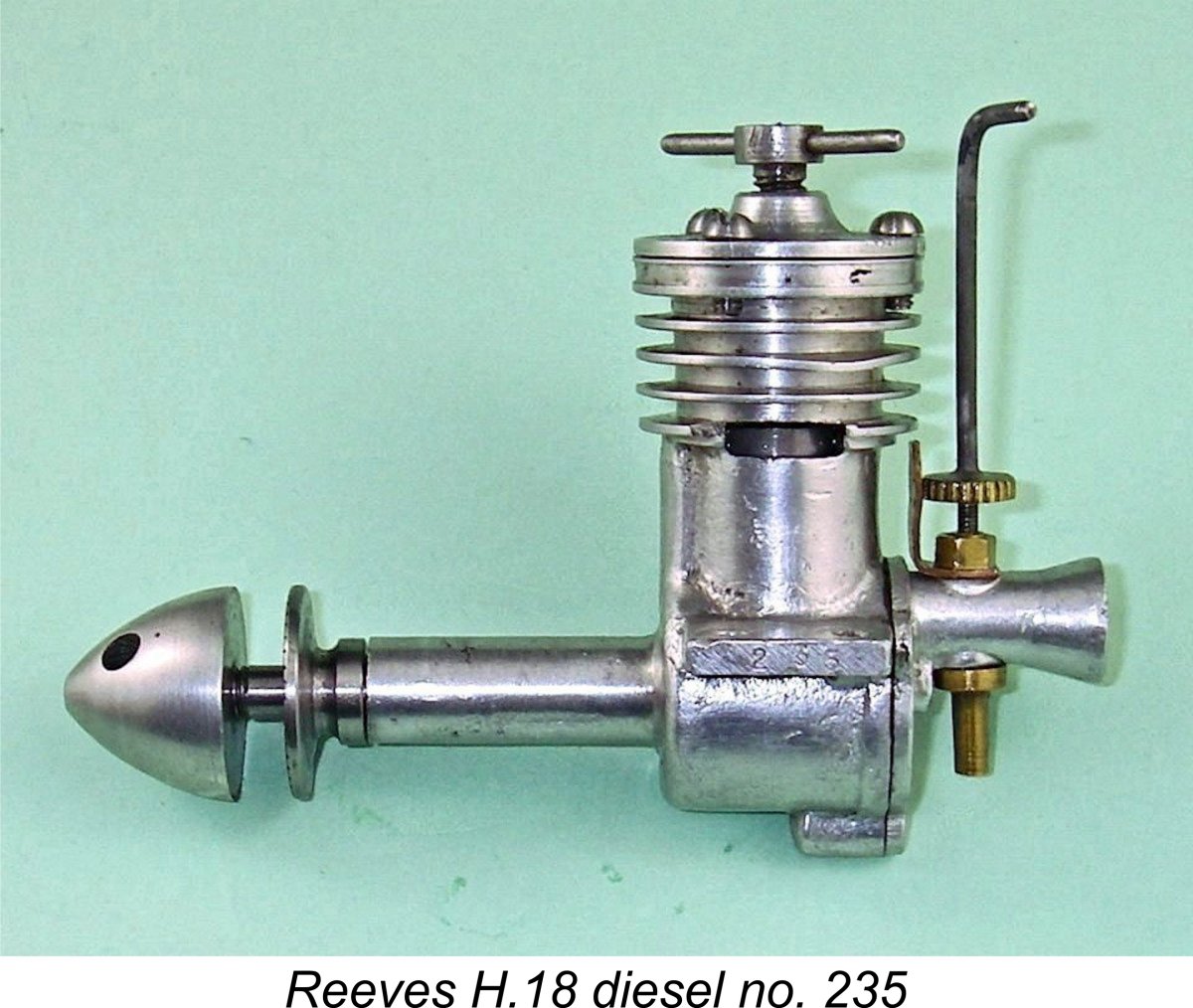
 which appeared in the magazine's October 1952 issue, the engine broke its crankshaft during the course of the test, and Chinn also reported that he had been unable to establish contact with the manufacturer to discuss the issue, nor was he able to obtain a second example for comparison purposes.
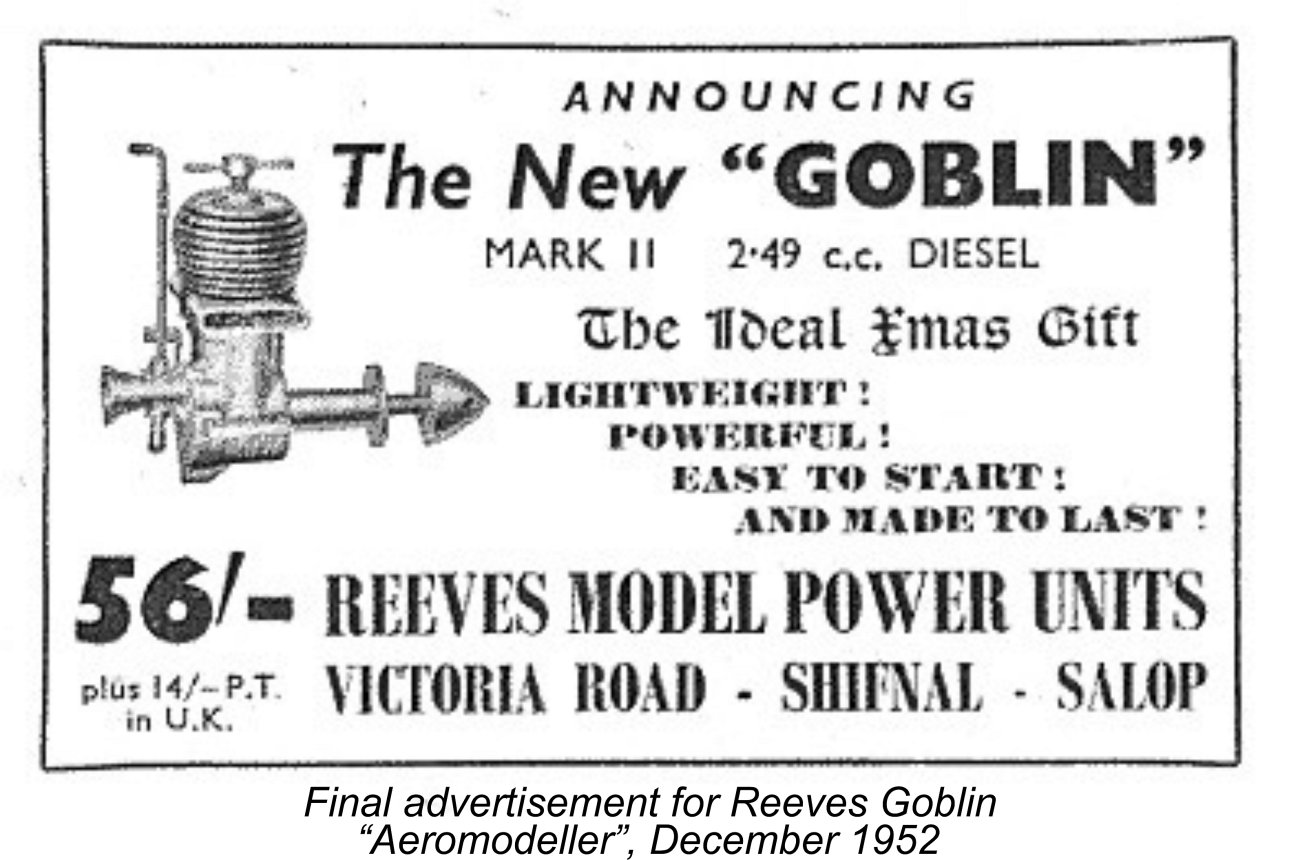 Returning to 1952, the fact that Chinn couldn't establish contact with Reeves in connection with his failed test of the Goblin implies that the maker may have already been in the process of winding up his affairs at this time. He must have had some previously-manufactured engines still to liquidate, because he continued to advertise sporadically, the final advertisement appearing in the December 1952 issue of “Aeromodeller”, still promoting the Goblin. This was the last that was to be heard of the Reeves model engine line.
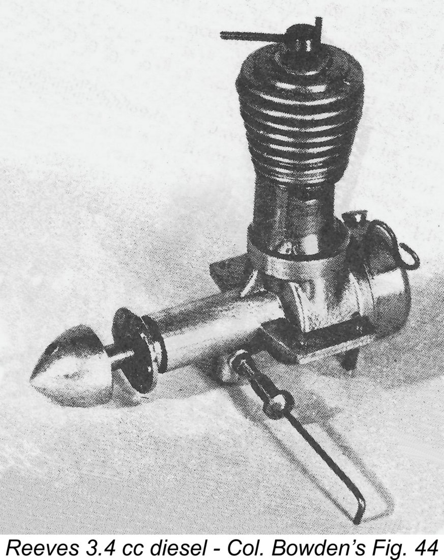 The Reeves 3.4 cc diesel was never the subject of a published test in the British modelling media. Indeed, its sole appearance in descriptive terms was its aforementioned inclusion in the 1949 second edition of Col. Bowden's book “
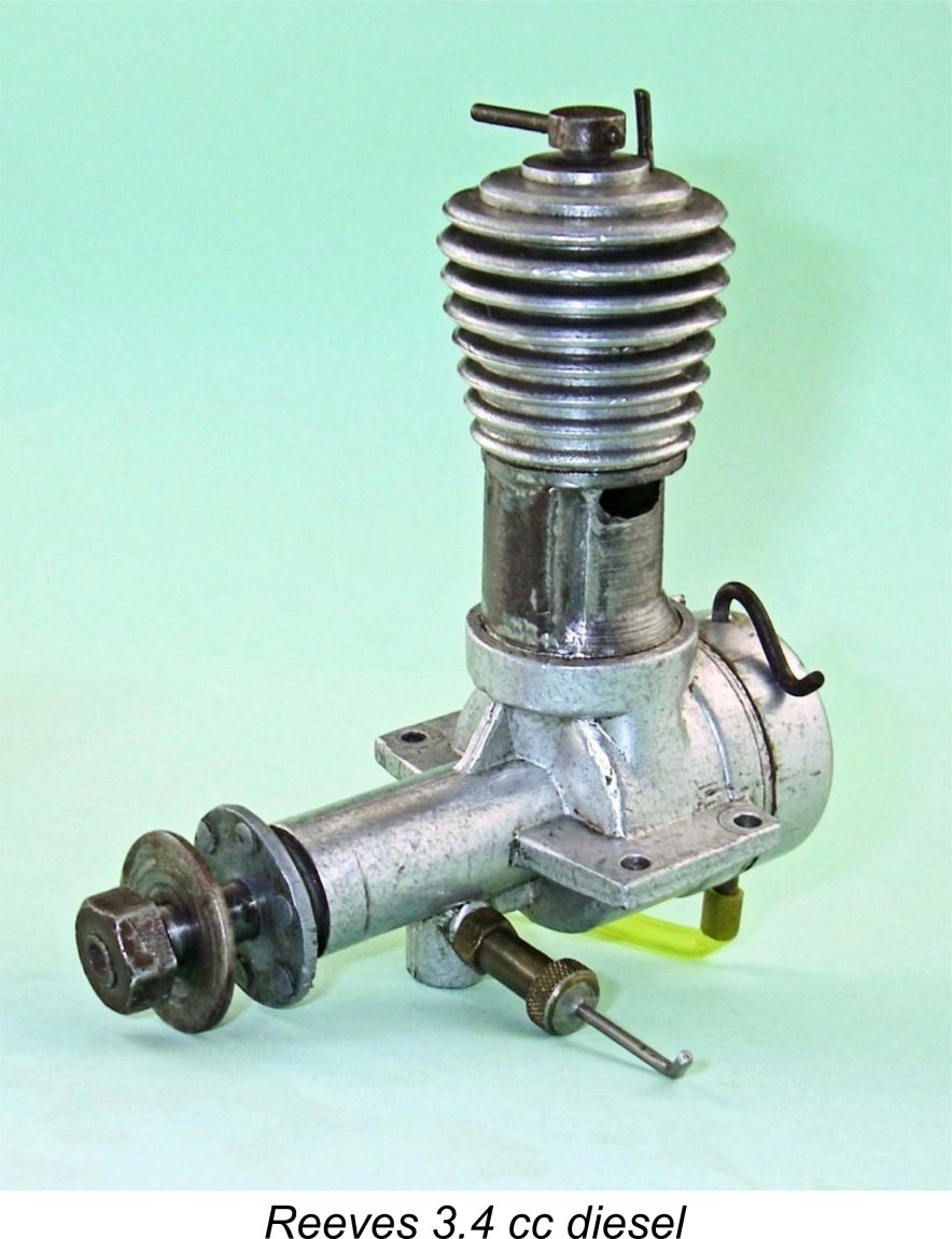
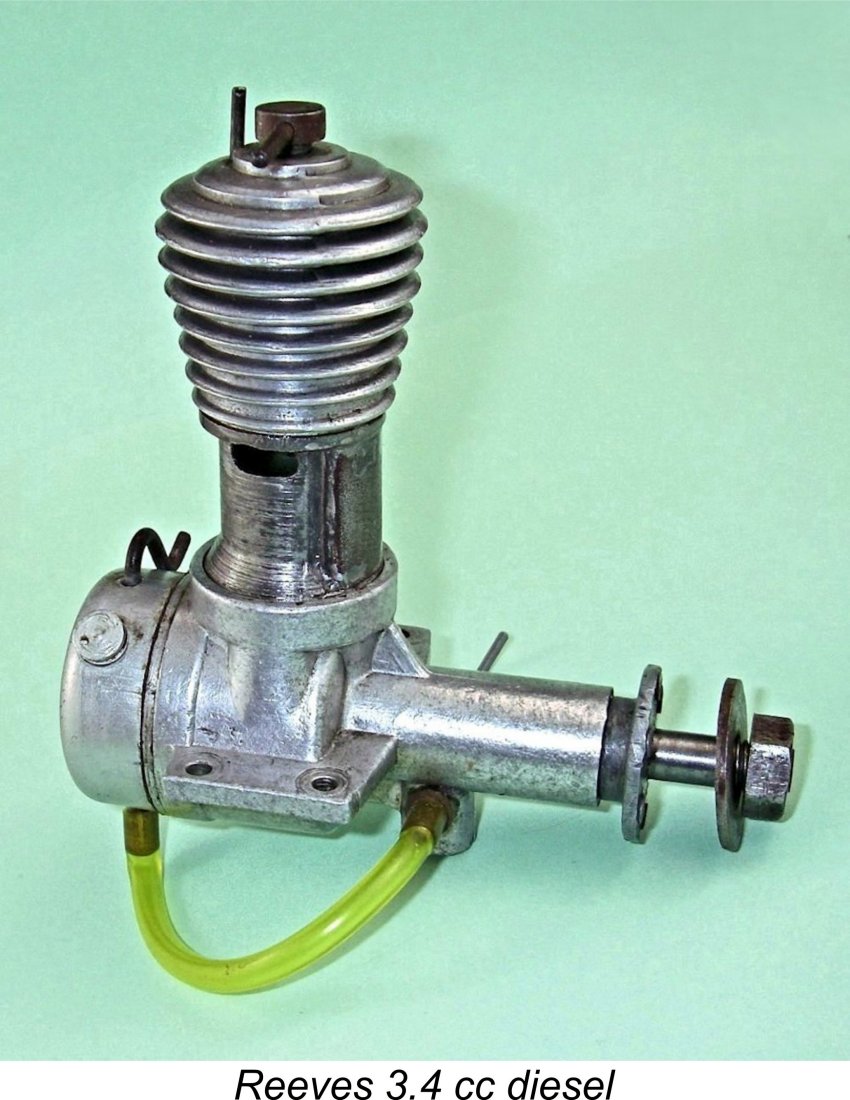 One's first impression of the Reeves 3.4 cc diesel is that it has a distinctly "old-fashioned" and "home-made" look, even by the standards of 1948. This is mainly due to the very tall cylinder coupled with the seeming lack of attention to the external finish of the unit. There's no denying the fact that the Reeves has a rather "agricultural" look about it!
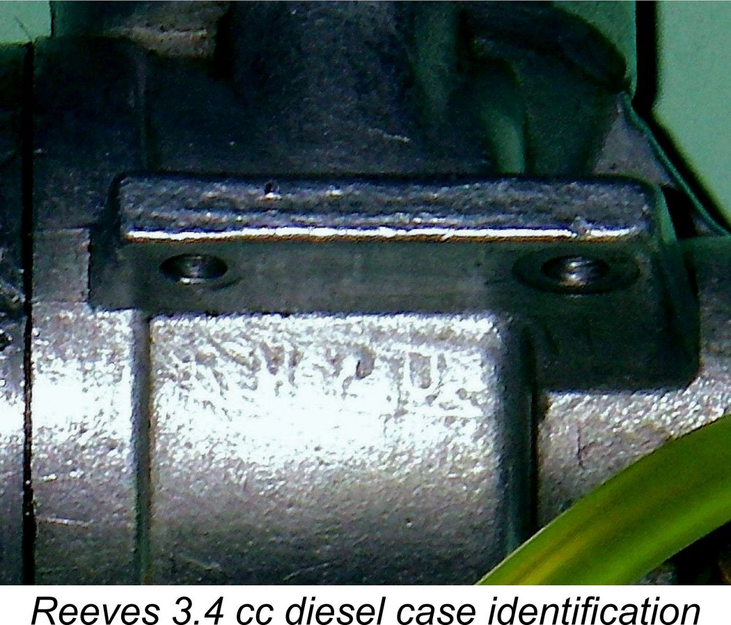 The engine bears no serial number, the sole identification being the letters RMPU cast rather indistinctly in low relief in small font just below the right-hand mounting lug (looking forward in the direction of flight). You actually have to look carefully to notice these letters! They obviously stand for “Reeves Model Power Units”. The very clear implication is that the change of company name had taken place by the time this engine appeared in early 1948.
 The bypass passage itself is formed by the space between the outer cylinder wall and a thin channel of plated brass sheet which is soft-soldered onto the exterior of the cylinder, rather akin to the system used on the
  manner adopted later by makers such as
  The con rod big end has an oil hole drilled in it for lubrication. It runs on a crankpin having a diameter of 0.218 (7/32) inches. The one-piece steel crankshaft features a disc crankweb with two cut-aways on the crankpin side for counterbalance. It has a main journal diameter of 0.345 (11/32) inches. The internal gas passage has a diameter of 0.218 (7/32) inches, yielding a wall thickness of 0.0635 (c. 1/16) inches. This gas passage is supplied with mixture through a circular induction port which registers with an updraft intake cast integrally with the main bearing.
 A conventional brass spraybar is used in conjunction with a needle carried in a split brass thimble for retention of settings. The die-cast aluminium alloy prop driver is a very close press-fit on a squared-off section of the shaft forward of the main journal. The shaft assembly is completed on both of my examples by a conventional nut and washer, although some examples such as that illustrated by Col. Bowden have a turned aluminium alloy spinner nut. It's possible that both styles were used.
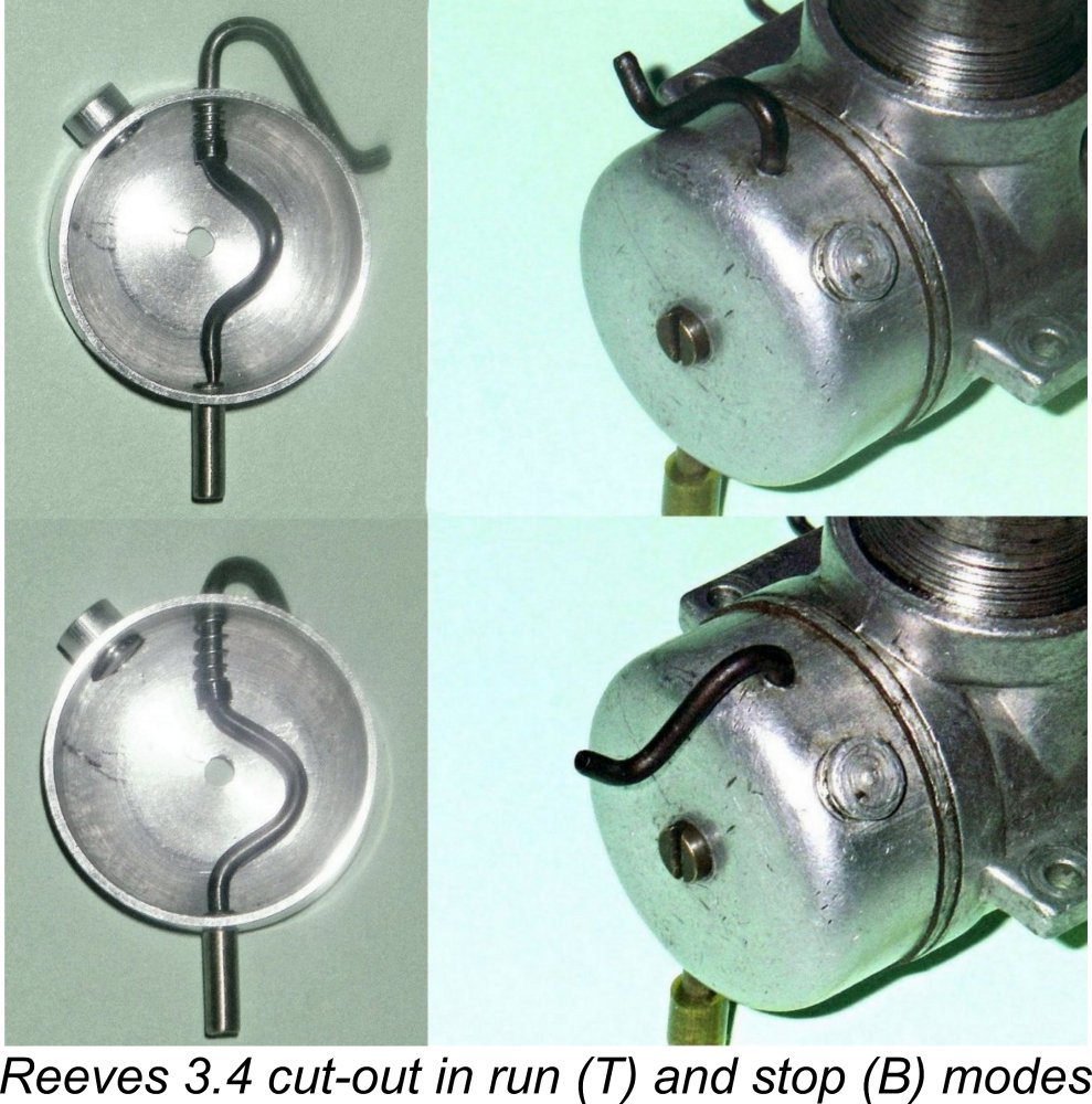 When the plunger is left free to move, the spring naturally forces the tapered point downward into the end of the fuel spigot, theoretically shutting off the supply of fuel. To open the fuel supply, it's necessary to pull the plunger upwards partially out of the nipple and hold it there for as long as the engine is required to run. But how to do this?
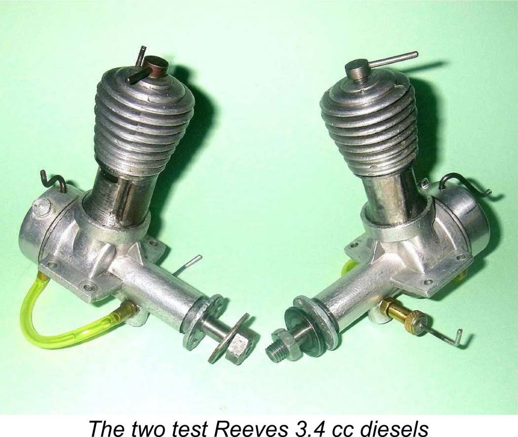 Being mindful of the recommendations in Ron Warring's tables while also recalling the long stroke and high reciprocating mass, I elected to begin testing on somewhat larger airscrews than I might otherwise have employed for an engine of this displacement. After thinking it over, I decided to start off with an 11x7 Zinger wood prop which I had on hand. Although this was actually less prop than the 11x8 recommended by Warring for control-line use, I still thought that it was too much for a 3.2 cc engine. However, time would tell.
 The back tank supplied with the engine is of course quite unsuitable for control line applications and would doubtless be removed in such cases. However, it does appear entirely suitable for free flight use. Running at its peak on the test 10x8 Top Flite wood prop using a leaned-out setting (and ignoring the gravity-induced fuel loss during starting!), the back tank gave an approximately 2 min 20 sec run including warm-up. This is more than adequate for free flight, the one limitation being that the non-translucent nature of the tank makes it impossible to see the fuel level for the purpose of timing the powered portion of the flight.
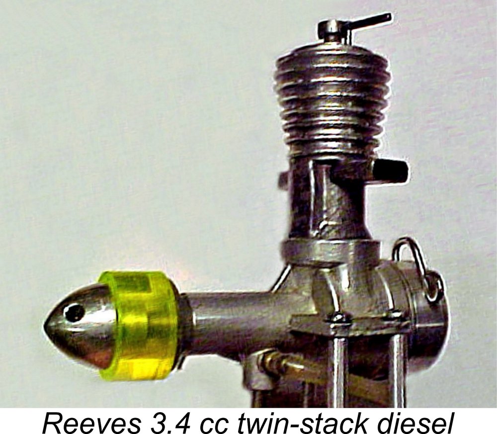 Following the initial publication of this article on MEN, I was delighted to hear from Graham Podd, who is well known both to collectors and engine builders. Graham advised that he had an example of the Reeves 3.4 cc diesel which is fitted with soldered-on exhaust stacks similar to those seen on many of the contemporary
 | |