
|
|
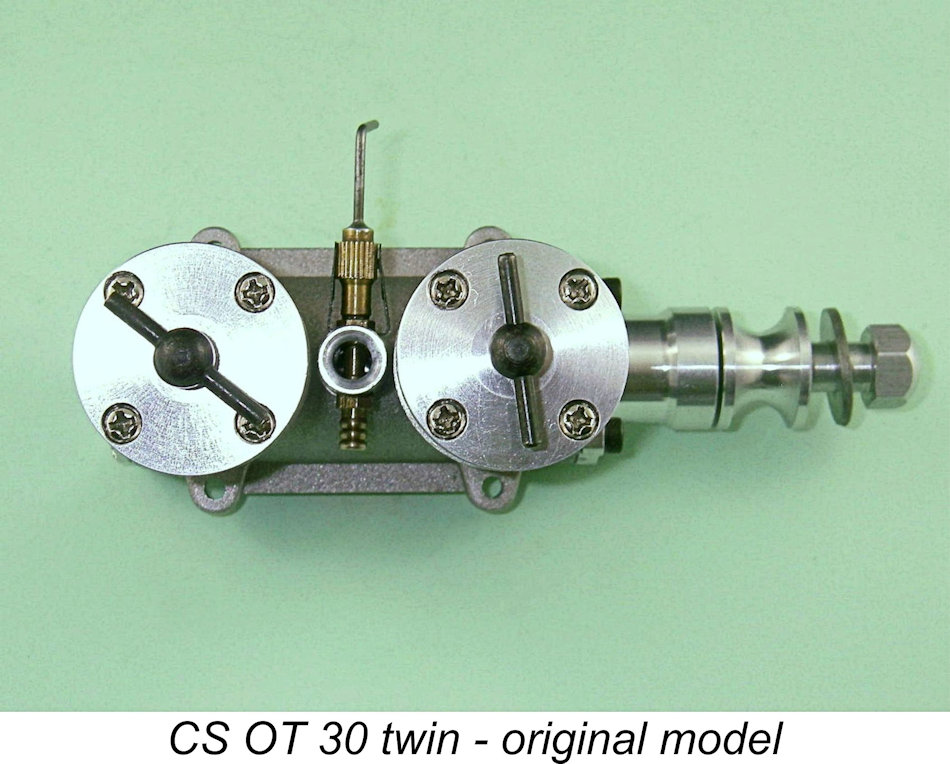
The CS “Oliver Twin” Diesel – an Impressive Accomplishment By Adrian Duncan with Maris Dislers
I was unwilling to risk the loss of reader access to the information so painstakingly gathered on the CS “Oliver Twin”, hence the article’s re-publication here. Indeed, much of the information presented here could no longer be assembled today, making it essential that it be preserved. Secondly, the original publication of this article had unexpected consequences. It turned out that CS were paying very close attention to my published articles dealing with their various products. Upon reading the original MEN article on the CS “Oliver Twin”, they immediately set about developing a revised version of the engine incorporating a number of the modifications suggested in the original article. They went so far as to contact me directly to keep me informed about their efforts, eventually sending me one of the test examples of the updated “Vision II” version of the engine for my review and comment. At this point they viewed me as a design consultant – I had input into several other designs.
Before setting about this task, it’s both a duty and a pleasure to acknowledge the immense level of assistance extended to me by my valued Aussie mate Maris Dislers. Although it’s my hand holding the pen, this article is very much a collaboration between the two of us. Thanks, mate! I must also express my very sincere thanks to Peng Han of Shanghai, China, who progressively took over the CS operation from its founder Gao Guojun beginning in 2007. Peng was not a professional engineer – he worked for a bank. However, he was a dyed-in-the-wool model engine enthusiast who loved all kinds of power models and particularly appreciated the unique aroma of model diesels – his first engine was a Yin Yan 1.5 cc model bought at the age of 11. His involvement with CS was driven entirely by his love of model engines. Peng was unstinting in his efforts to support our research into the CS “Oliver Twin”, for which I wish to thank him most sincerely. Now on with the tale, beginning with the background to the appearance of this very interesting engine. Background Among the legendary products manufactured in England during the 1950's by the famous Oliver workshops were a few in-line twin cylinder diesels which were constructed by the Olivers in prototype form as experiments. These engines were never envisioned as commercial offerings - the cost of their manufacture and the limited number of potential customers doubtless combined to make such a venture appear economically unsustainable. It's not completely clear how many of these prototypes were actually made, but the number cannot have been significant. The Olivers went on to construct a number of additional twin cylinder prototypes, both in-line and opposed, well into the early 1970's. The Oliver Twins were covered in John Goodall's well-known and highly recommended book on the Oliver engines entitled "The Olivers and a Tiger". Readers wishing to learn more about this very rare series are recommended to this excellent work, which at my original time of writing (April 2012) was still available in soft-cover form from the author. I'm not sure about present-day availability.
The engine appeared to be in effect a twinning of the standard Oliver Tiger Mk. III. It reportedly utilized an ingenious form of surface rotary valve consisting of a central flywheel having a radial port formed in its outer edge which fed the two crankcases alternately. However, that was about as far as it went at the time. Ron Moulton characterized the engine as "a beautiful project too expensive to repeat in numbers", and the engine was consigned to the status of legend, with no realistic expectation of any interested individual ever being able to acquire one. Apart from its mention in John Goodall's book, little further attention has since been paid to this very interesting design. I have no idea of its present-day whereabouts.
Over the previous two decades or so, CS had produced an astonishing array of replicas or semi-replicas of classic model engines from such brand-names as Micro Diesel, Deezil, Barbini, AMCO, Rivers, Elfin, Mills, Yin Yan, E.D. and of course Oliver. Generally speaking, these followed the original design configuration fairly closely but frequently displayed detail departures which rendered them somewhat less than faithful replicas. They also displayed quite wide variations in quality. However, the better examples were found to give good service if thoroughly checked and well prepared prior to use. This being the case, the news that CS had actually produced a run of in-line rotary valve diesel twins based upon their own CS Oliver "replica" caused quite a stirring of interest, reviving recollections of the former existence of the “genuine” Oliver Twin! I was quick to get my hands on an example with the objective of analyzing and testing it to see how well CS had met the undeniable challenge of making such a relatively complex product. Fortuitously enough, my Aussie friend and colleague Maris Dislers also took the plunge at about the same time. I am thus able to include a sizeable number of Maris's always-valued observations in the present article. My sincere thanks to Maris for this collaborative effort!
In fairness, it doesn't appear that CS themselves ever saw this as anything more than an in-line twin cylinder diesel of their own design based in large part upon components of their own “replica” Oliver Tiger Mk. III which were already in production. They never claimed that it was a replica of any earlier production by the Olivers. The official name of the engine on the company website was the CS OT Twin 30 - no overt mention of Oliver there, although the OT presumably stands for Oliver Tiger. So we're not dealing here with a replica of one of John Oliver's legendary twins – the Olivers had If I was asked to point towards an earlier diesel twin which might have influenced the design of this engine, I would probably think of the Alag 5 cc diesel twin of 1958, which was based upon the 2.5cc Alag X-3 single-cylinder unit. The general design layout of the CS twin appears to follow that of the earlier Alag model in many respects. That said, this was a very interesting engine indeed which was well able to stand on its own legs and be judged on its own merits. So without further ado, let's get into an examination of what was undoubtedly CS's most ambitious diesel project. General Description
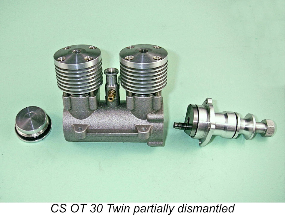
Taking the single illustration of the original Oliver Twin in Ron Moulton's 1959 article as our guide, a number of design departures were immediately apparent. Apart from the comparatively "square" cooling jacket profile lifted straight from the single-cylinder CS Oliver “replica” model, the front cover of the CS Twin was a bolt-on unit as compared with the screw-in component apparently used on the original Oliver Twin. Moreover, the intake location was different - the CS version featured a vertical intake set between the two cylinders, while the original Oliver model had its intake installed in a The mounting lugs were also different. Those on the original Oliver Twin were simple lugs having parallel faces along their entire length. By contrast, the CS offering featured major expansions at the mounting hole locations, with far skimpier bracing lugs joining them. It must be admitted that the original design seems to be the sturdier of the two. That said, several of the later reed valve Oliver Twins used the same lug design as that seen on the CS variant. One feature that didn’t excite my In keeping with my usual practice with CS engines, I refrained from even turning the engine over pending a thorough clean-up during the course of my internal inspection. However, the initial impression was that this engine was quite well-made in most of the key areas. I therefore faced the continuation of my self-appointed task with some confidence! To learn more about the CS OT Twin 30 and to prepare it for action, we have to take it apart. Let's get to it .......... Internal InspectionAs I got on with the job of dismantling the CS OT 30 Twin, it became increasingly apparent that the easiest way to describe this engine's design and construction would be to start with the engine in pieces and follow the stages of reassembly. This is one of those engines that is most easily characterized through a description of its major components as they go together.
As matters stood, any attempt to run this particular unit without a prior clean would doubtless have led to highly negative consequences. Maris Dislers had exactly the same experience with his example acquired at around the same time. Once I had it down to its components, the design became completely clear. A further aid to clarity was the receipt of a factory parts list from Maris Dislers, complete with an exploded view of the engine. Reference to this diagram should help to make the workings of the engine perfectly understandable.
The CS Twin used two separate but interconnected crankshafts. The front shaft was perfectly conventional, looking in fact very much like the CS Oliver single cylinder crankshaft with a central 5.5 mm diameter gas passage being retained, presumably to reduce weight. However, the induction port and associated FRV venturi were naturally omitted since they were redundant in this design. The retention of the central passage The front shaft was supported by a fully machined front housing which incorporated two ball races, exactly like its single cylinder relative. Main journal diameter was 10 mm, stepping down to 6 mm at the front ball race locating shoulder. The steel shaft had a counterbalanced crankweb with an integrally-machined crankpin. Inspection of this assembly revealed the first major glitch in this engine's construction. Both of the ball-races were of the shielded type. This made a certain amount of sense for the front bearing, since it inhibited the entry of external dust or dirt into the bearing. However, at the rear it made no sense at all. In this engine, it was essential that oil be completely free to pass through the rear ball race into the plain bearing section and thence to the front ball race, since in the absence of an FRV induction system this is the sole source of lubricant supply for those bearings. The shield used was quite a close fit – a test showed that the bearing would retain fuel that was poured into the cage under gravity. The use of such a bearing at the rear is more or less a guarantee of oil starvation for the plain bearing section and the front ball race. I fixed this in my example simply by popping the shield out of the rear ball race and re-installing it. While I was at it, I did the same for the front bearing to allow the free passage of lubricant and the purging of impurities through the bearing during operation. It would have been wise for CS to use unshielded components as the standard fittings, particularly at the rear of the front housing. I'd recommend this modification for any example of this engine that was going to be run. The prop driver used with this shaft appeared to be the same component employed on the CS Oliver single cylinder model. It was secured to the shaft with a brass split collar. Oddly enough, no washer was supplied to go along with the aluminium alloy sleeve nut used to attach the prop. I quickly remedied this deficiency on my own example.
The front crankpin incorporated an extension of reduced diameter (4.38 mm in my example) starting just aft of the conrod bearing length. This engaged with a 5 mm hole in the front web of the central crankshaft assembly, thus constraining the two shafts to turn as one with the crankpins set 180 degrees apart. The fact that the engagement extension on the front crankpin was slightly undersize was presumably intended to allow some leeway to accommodate any slight incidental misalignment between the front and central shafts. I would expect considerable chatter to occur at this point, probably leading to increased play between the shafts as running time built up. The central crankshaft was undoubtedly the heart of the CS Twin. It was of composite construction, the rear section incorporating both the 12 mm diameter main journal and the rear crankweb with integral 5 mm diameter crankpin. The main journal was once again carried in two ball races with a plain bearing section in between. The web which engaged with the front crankpin as described earlier was a separate component which was permanently mated to a shoulder machined onto the front of the central shaft. My mate Jon Fletcher confirmed that the two components were simply force-fitted or perhaps shrunk together, with no other provisions for security. The structural integrity of the central shaft assembly was the most crucial aspect of the design - the entire success or failure of the engine depended upon it. The design was such that the front web was not subject to bending forces as it would have been if the front crankpin were integral with it - a good design feature. It was however subject to cyclic torsional stress reversals of some magnitude during normal operation. The apparent reliance upon force-fitting or shrinking to join the components appeared to be somewhat on the marginal side - any failure or slippage of this joint would immediately render the engine inoperable. In fact, as we went to press with the original version of this article in 2012, we learned that precisely this failure had been experienced by an Australian OT 30 Twin owner. This reportedly occurred during the break-in process. By the owner's own rueful admission, it may have been caused by over-compression of the rear cylinder, a condition which would inevitably increase stress levels in the inter-shaft connection. I confess to a sneaking suspicion that an electric starter may have been involved too ..........regardless, it's nice to be able to report that the company responded immediately to the owner's request for assistance, agreeing to repair the engine free of charge upon its return to the factory.
MEN’s Editor, the late Ron Chernich, recalled a method of keying the crankweb to a separate shaft by drilling one or two blind holes centered on the join line, tapping them, then inserting an Allen-head grub screw with a drop of Locktite for added insurance. This would preclude any possibility of slippage, either axially or radially. While it could be performed by an experienced model engineer in a reasonably well-equipped shop, the modification would have been far more easily carried out at the factory before the assembly was inserted in the crankcase. This form of construction would also have facilitated the dismantling of the centra shaft for servicing if required. As it was, the central shaft couldn’t be removed for inspection or servicing of the bearings. Hence this was as far as the disassembly process could proceed. Fortunately, the central shaft bearings in my example felt good, although the front central shaft bearing in Maris's engine reportedly felt a bit lumpy and could have done with a closer inspection if that had been possible. That said, it seems to have held up in service (see below). The rotary valve arrangements were not unlike those adopted during the 1950's for the well-known K&B-Allyn Skyfury twins, albeit without the split central bearing used in that design. The central shaft was drilled at a diameter of 5.25 mm from both ends to a depth which left some 5 mm of material between the two opposing gas passages formed in this way, thus keeping them completely independent with each feeding one of the two crankcases.
As stated earlier, the success of the engine depended to a significant extent upon the matching of the two induction systems to minimize differences in mixture distribution between the two cylinders. My example appeared to have been fine-tuned by hand-grinding to some extent in order to match the timings for the two cylinders as closely as possible. Timing was extremely conservative, in part due to the relatively small 5.35 mm diameter base of the venturi intake mounting coupled with the 5.50 mm diameter induction port openings in the very large 12 mm diameter journal. The timing of my example was very closely matched for both cylinders, opening at around 87 degrees ABDC and closing some 18 degrees ATDC for an induction period of only 111 degrees. This was supplemented by a sub-piston induction period of some 20 degrees - 10 degrees either side of TDC. With the ultra-conservative induction timing adopted, some degree of sub-piston induction was undoubtedly necessary – in fact, I felt that a somewhat greater sub-piston induction period would have been desirable. The use of such a large diameter journal naturally resulted in a high surface speed during operation. This resulted in quite rapid opening and closing of the induction ports. The functioning of the induction ports was further enhanced by the 45 degree angle at which the induction ports were drilled, since the resulting port openings at the journal surface had an oval shape, further increasing the opening and closing rates as well as the port register area. Considering the relatively short induction period provided, the system could clearly use all the help that it could get! In fact, the engine would almost certainly have performed better if the crankcase unit were machined prior to assembly to allow significantly earlier opening of the induction system. This could easily be done at the manufacturing stage by milling at the appropriate angle. The middle portion of the central shaft was clearly a potential point of structural fragility given the fact that it was weakened by the presence of two induction ports as opposed to the usual one. The cyclic torsional stresses generated by the operation of the rear cylinder would necessarily be transmitted through this area of the shaft. The very generous main journal diameter of 12 mm along with the relatively modest 5.25 mm diameter internal gas passages was clearly a very rational design response to this issue. The fact that all ports were rounded should have also helped to minimize any tendency towards the creation of stress concentrations at this always-vulnerable point in any crankshaft rotary valve engine. Provided the material and heat-treatment specifications were appropriate (which they have not always been with CS engines), I would actually expect little trouble at this location. As of the original time of writing (April 2012) and for some years thereafter, my expectations had been fulfilled.
When reassembling the engine, it seemed best to start with the front cylinder section. The front housing with its shaft installed was presented to the front crankcase, the front con-rod being fitted to the crankpin on the way in prior to engagement with the central crankweb. No gasket was used, reliance being placed entirely upon good metal-to-metal contact. Once this assembly was complete and the bolts tightened down, I checked that the composite shaft assembly turned freely. My example was very good as received, but Maris had to do a little stoning down of the front crankpin extension to get his example turning over smoothly. A friend of Maris's who bought a similar engine found that while his example was generally well fitted, he had to install a fibre gasket between the front housing and the case to move the front housing forward slightly, thus preventing binding of the two crankshafts at the crankpin.
The needle valve assembly appeared to be a standard CS Oliver unit. On my example, the needle taper was ground out of true with the needle shaft. Since this would have caused very erratic needle response, I re-ground the taper prior to installation. This is a point worth checking on any CS engine if you want it to needle reliably. The front cylinder could now be fitted. There was a certain amount of flash left in the lower ends of the transfer ports on both of my cylinders, which I naturally removed prior to assembly. A good feature was the Once fully assembled, I could get a feel for the fit of the front piston. Mine felt very good as received, and Maris had a similar experience. It's interesting to note in passing that the engine would undoubtedly run as a single-cylinder unit in the form achieved at this stage! In this form, it is in effect a 2.5 cc rear drum valve single cylinder diesel of conventional type. The opening and closing of the "dead" rear induction port might affect The rear cylinder assembly was completely conventional, being identical in all respects to that of the CS Oliver single. It went together in the usual way, with attention once more being paid to the consistent alignment of the cylinder liner using the notch mentioned earlier. Once again, the piston fit in my example seemed to be very good. The engine was completed by the installation of the screw-in rear cover. In typical CS fashion, the rear cover was very effectively sealed through the use of an O-ring. The exhaust period for both cylinders was set at around 160 degrees. The blow-down period was only a matter of 5 degrees or so, giving a transfer period of some 150 degrees. Given the induction timing involved as well as the anticipated speed range, I reckoned that the engine would likely perform better with a somewhat lesser exhaust period, with transfer period reduced to match. An exhaust period of around 140 degrees with the transfer period at around 130 degrees would almost certainly yield superior results in terms of torque development. Anyway, there we have it - one cleaned-up and re-assembled CS OT 30 Twin all ready to go! Next question - how does it actually run? Only one way to find out............ The CS OT 30 Twin On Test
A few glitches became apparent immediately. The front contra piston was too loose and tended to run back, while the rear contra-piston had the opposite problem - it was too tight! Despite these challenges, Maris got a few runs onto the engine, finding that the needle setting was relatively non-critical. Starting remained perfectly straightforward at all times. Most encouragingly, the exhaust residues showed no sign of the dreaded polychromatic black coloration which usually means that a conrod bearing is being burned off. I had seen that before with earlier CS engines ............. After a bit of running, Maris was able to measure 10,700 RPM on the 10x6 Taipan. Based on the approximate power absorption coefficient developed for that prop over years of testing, this equates to around 0.42 BHP at this speed. Not bad, but hopefully there was more to come! One issue noted by Maris was the fact that while the front cylinder seemed to be on full song, the rear cylinder appeared to be a bit behind, seemingly operating less efficiently. No amount of fiddling with the compression screw would put this right. Maris noted particularly that when the engine was starved of fuel by pinching the fuel line, the rear cylinder invariably quit first. All of this seemed to imply that mixture distribution between the two cylinders was not completely uniform. It must be said that this was hardly a surprising finding. Evidently the rear cylinder was running leaner than the front one. Following some more break-in runs, a more serious problem presented itself to Maris. During the course of a run, the front bearing galled up and seized in the plain bearing section between the ball races. It will be recalled that I noted the potential for oil starvation of the front bearing due to the use of a shielded rear ball race on the front shaft of my example. Upon inspection, Maris's engine turned out to be similarly equipped, which doubtless contributed to the problem. Naturally, he followed my earlier example in removing the shields from both front bearings.
Maris commented that he had always relieved the fit of the plain bearing section in his own CS "Oliver Tiger" singles to create a radial clearance of around 0.03 to 0.04 mm (~1 thou.). This apparently improves running significantly. Both Maris and I relieved the rather tight fits in our OT 30 Twins accordingly. While Maris had his example apart, he also took advantage of the opportunity to fit new con-rods having a 1 mm greater length between bearing centres. This resulted in more conservative exhaust port timing of 138 degrees as opposed to the 160 degrees as supplied. As noted earlier, the reduced figure seems far more in keeping with the engine's very conservative induction timing. The longer rods also increased the sub-piston induction period to some 45 degrees, which should certainly help the induction cycle. An incidental benefit of this approach was the reduction in the swing angle of the rods, with a consequent reduction in side-thrust loadings. A further issue noted by Maris during the course of this rebuild was the fact that the front piston was out of round by some 10 microns, resulting in the development of hot spots and dirty running. Maris did what he could to ease this problem before re-assembling the engine. Then it was back to the test stand, where the rebuilt engine proved itself to be a fine starter and runner – the former discrepancy between cylinders seemed to have been largely overcome, probably due to the extended sub-piston induction period. After a little running-in to settle the new rods, the following figures were obtained:
There’s an obvious discrepancy between the power figures derived at almost the same speeds for the APC 10x4 and the Graupner 9x5 - Maris appears to have missed the setting on the Graupner airscrew. Even so, it's abundantly clear from these figures that the engine came nowhere near matching the factory claim posted on the CS website of 1.1 BHP at around 10,500 RPM. Peak power was obviously significantly less, also being released at substantially higher RPM. Moreover, Maris's figures were taken from a heavily modified unit, hence not being necessarily representative of an off-the-shelf example.
In actual fact, Maris's reworked CS twin seemed if anything to outperform such iconic designs as the Fox 35 Stunt. It would undoubtedly do a creditable job of flying a sport-stunt control-line model designed for classic powerplants in the .35 - .40 cuin. range. Its main disadvantages would be its weight and its noise characteristics - that un-muffled high-pitched shriek is music to the ears of a dyed-in-the-wool engine enthusiast like me, but would not be welcome at many flying fields! An Air Test of the CS OT 30 Twin
All-up weight of this model with the Twin fitted was a little over 1 kg (~ 36 ounces) - somewhat heavy for a Ringmaster. Naturally, a shorter nose with the fuel tank located in the wing would avoid the 50 gm tail weight, but much of the weight was from Sterling’s rather heavy kit wood. Even so, Maris felt that it should be possible to build an 850 gm (30 ounce) Ringmaster with this engine - still not ideal, but a bit closer to a desirable weight.
The engine’s performance in this model undoubtedly confirmed Maris’s opinion regarding its potential usefulness as a practical engine to use in a model. Better yet, the composite shaft held up! Following its period of basking in the sun, the engine has since been retired to the display shelf, still in good operating condition. Further Testing of Another Example
Vibration levels proved to be very low, as one might expect - the main issue here is the fore-and-aft rocking couple which is unavoidably developed between the two cylinders. The very wide mounting hole spacing is of course well suited to resisting these forces, added to which the engine's mass doubtless helps to absorb vibration. After a little running, the exhaust color cleared up nicely and I briefly saw 10,600 RPM on the Taipan 10x6 - very close to Maris's initial finding. However, after about 30 minutes of break-in running, things suddenly went seriously pear-shaped. During another break-in run with the engine well on song albeit a tad rich, the rear pot suddenly quit. Clearly a mechanical failure, so I stopped it immediately. It turned out when I got it home that the gudgeon pin for the rear cylinder had been very marginal for length. I’d had previous experience with CS gudgeon pins being too short, so I had checked this. However, I did so without actually removing the pin, and I now think there must have been some junk in the boss which hung up the pin and misled me. Regardless of the reason, one end of the pin had slipped out of its boss while the engine was running. The result is easily imagined - I lost the rod and the piston, although the bore looked OK. So the engine came apart once again so that a new replica rod and piston could be made and fitted. While it was apart, I re-checked the front gudgeon pin very carefully, finding that its length was perfect.
So... back to the test stand! The engine proved to be as easy to start as it had previously, and I had no trouble getting it settled into a nice break-in mode of operation. I put on 30 minutes in 5-minute runs with no problems at all, mainly to break in the new rear piston and rod. At this point, the engine felt superb, encouraging me to try a few props to get an idea of the performance levels being realized at this stage. Results were as follows:
The figure for the 10x6 indicates that the engine's performance had not suffered appreciably as a result of my home rebuild. The slight drop-off may simply have reflected a need for more running-in of the rear cylinder with its new piston. However, there seems to be little doubt that my engine didn’t approach the torque development of Maris's example with its lengthened rods, extended sub-piston induction period, plugged front shaft and adjusted port timing. It seemed evident that my engine in its basically stock configuration peaked at between 12,600 and 13,900 RPM since the power developed at these speeds was very close. I'd guess around 0.53 BHP at somewhere in the region of 13,400 RPM. Plenty of power to fly a model. Indeed, it must be said that if anyone had managed to produce a radially-ported twin-cylinder alternate-firing diesel having this level of performance back when the technology which it embodies was current, it would have been hailed as a major achievement. Hats off therefore to CS for a very impressive design effort! A few tweaks plus some attention to the quality control issue, and they would have had have a truly remarkable product here. Some Handling TipsThere are quite a few videos on YouTube these days showing people running twin-cylinder diesels of various types. A common denominator in these pieces is the revelation that many owners appear to be working in the dark when it comes to a clear understanding of the somewhat black art of getting the best out of such an engine. Hence it seems worthwhile to include some hard-won advice on the management of twin-cylinder diesels. I don't pretend to know it all, and others may well have approaches that work better than mine. I can only share the approach which I myself have found to work effectively over the years. To begin with, it's necessary first to have a clear understanding of the goals that we're trying to achieve. First, we want to get the engine running at the lowest compression settings on both cylinders that permit smooth and efficient operation without misfiring. This is actually one significant advantage of the use of compression ignition in a twin-cylinder engine - one retains direct independent control of the ignition timing in both cylinders during operation, a facility which glow-plug ignition does not provide.
Third key point - do NOT be tempted to use an electric starter on one of these engines! This is good advice for any diesel, but it's particularly important for a twin-cylinder unit like this in which a hydraulic lock in one cylinder can easily “sneak up” on you. The consequences of a hydraulic lock in either cylinder would be terminal if a starter were to be used. In any case, there's no justification whatsoever for the use of a starter, since once you've established the settings, this engine is extremely easy to start by hand, never needing more than one or two flicks. The next imperative is to make suitable arrangements to mount the engine. Do not be tempted to mount the CS OT 30 Twin in a conventional test stand using the thinner central portion of the mounting lugs! There simply isn't enough metal there and the overhang is too great - distortion of the case or even fracture of a lug would be a very real possibility. Moreover, the rocking couple between the cylinders would be very poorly resisted, doubtless leading to high vibration levels with the very real possibility of a fatigue failure. Far better to do as Maris and I did and make up a mount using full-length hardwood engine bearers as featured in the illustrations. Now let's suppose that we have a CS OT 30 Twin (or a similar alternate-firing twin cylinder diesel) all set up on the bench ready to test. The engines are clearly not test-run at the factory, so there's no guarantee that they are correctly set as received. In fact, we can almost guarantee that the engine will not be correctly set! How best to proceed? When tackling twin-cylinder diesels, I always start with the compression settings. Over-compression is the real enemy, so during the rebuild process described earlier (without which I would not so much as attempt to start one of these CS units), I slacken off compression in both cylinders by pressing the contra-pistons a little further up the bores. Once assembled, I adjust the comp screws so that both cylinders feel the same when the engine is turned over and then screw them down progressively by small increments until the setting on each cylinder "feels" right when the engine is turned over slowly by hand with a prop fitted, something which long experience of diesels allows me to do fairly accurately. Usually, the settings reached in this way will be found to be somewhere near correct, and I'll obtain a quick initial start. If you don't have the experience required to set the compression roughly by "feel", it seems best to work on one cylinder at a time to establish a setting. Leaving the rear cylinder at the low setting established during the rebuild, treat the engine as a single cylinder unit and work on the front cylinder in the normal way as if it was a single-cylinder unit - prime, flick and assess results. Keep screwing the compression down by small increments until the thing begins to fire. Then increase the compression in the rear cylinder until it feels more or less the same as the front one when turned over by hand. The two cylinders should now be somewhere near the correct starting settings. A little more compression in each cylinder (and I do mean a little!) should be all that's required. Now it's time to connect the tank and fill it with fuel. As far as the needle goes, CS needles are set all over the map, so it's impossible to suggest a setting. It seems best to begin with it open around 4 or 5 turns and check that fuel is drawn fairly smartly through from the tank when the engine is turned over by hand with the intake finger-choked. This should be an OK setting for attempting a first start. From this point on, dry-prime both cylinders before each attempt and increase the compression settings by the same (small) amount each time if required. Make sure before you flick that you haven't over-primed and created a potential hydraulic lock in either cylinder. Actually, this is pretty hard to do given the fact that the balance between the two cylinders encourages the engine to come to rest between flicks with both exhaust ports closed, all ready to receive a dry prime. Starting is now pretty much the same as with a single-cylinder engine. On my own example with the compression set initially by feel as described above, the engine started immediately and kept on running on the front cylinder only, but a small catch-up increase in the compression setting of the rear pot with the engine still running quickly brought it into action as well. This kind of "single cylinder start" is not uncommon with engines of this type. If the engine starts running but dies almost immediately, open the needle a little and try again. If it starts up but then more or less "slobbers" to a halt with lots of fuel and oil being ejected, it's too rich - close the needle down a little. In this latter case, you can almost certainly dispense with the prime for the next starting attempt, and you may have to back off compression a little in both cylinders. Once running, things are complicated by the fact that you have two independent compression settings with which to deal. The idea is to get both cylinders firing smoothly and thus contributing equally to the engine's output, using the lowest compression settings that allow this to happen. There's a fair bit of trial and error involved here, and the trick is to make all adjustments in small increments. Some of the adjustments seen on YouTube make me cringe ............... First try the effect of increasing compression slightly on one cylinder. If the speed picks up, try the same thing on the other pot. A further increase in speed means that you're on the right track. Work on the two cylinders alternately, using small adjustments at all times. Alternatively, if the thing slows down when compression is increased in either cylinder, back off compression on that cylinder! If you can hear a misfire in the exhaust note (as you probably will at this stage), it's vital to determine which cylinder is the culprit (unless they both are!). Looking at the exhaust is a useful indicator—those puffs of white smoke are a dead giveaway - but the tip of a finger held where you can feel the exhaust emissions without getting barbequed is perhaps ever better. You can easily feel the erratic exhaust of a mis-firing cylinder. Try the compression control on that cylinder to see if you can eliminate the misfire that way. If you can't, it's a mixture issue. Once the thing is running as well as you can get it using compression alone, it's time to tune the needle valve. Here the issue is that it's highly unlikely that mixture supply between cylinders will be uniform, regardless of the designer's best efforts. So you have to use your eyes as well as your ears. Try the effect of leaning out the mixture. The engine will most likely pick up somewhat. If you can't find a setting at which the engine two-strokes smoothly, it's back to the compression - get it running as well as you can using the needle, and then make small adjustments to both cylinders in turn until best running is achieved. Then go back to the needle once more. There's a lot of trial-and-error here, and the secret is to make small adjustments, alternating between compression and mixture controls.
The final step is to optimize the compression settings. With the needle at its now-established lean setting, reduce compression on each cylinder in turn by small degrees until a misfire creeps in and the engine begins to slow down. Then increase slightly past the point at which the misfire disappears, and there you are! Repeat for both cylinders and you should have the engine running at its best on the fitted prop, with a clean exhaust and no misfiring. You can try the effect of marginally increasing the compression settings in turn, but a point will be reached where the engine begins to slow down again, at which point it's definitely time to back off a little! The lowest compression settings at which both cylinders are running efficiently is the goal to aim for. During the first few runs, keep the needle slightly rich and monitor the state of the oil thrown out by the exhaust. A new engine will often have a dark coloration to the oil, but this should clear up fairly quickly as the parts become mated to each other. If it persists, and particularly if it has a black polychromatic appearance, note which cylinder is the culprit (unless both are!) and stop the engine immediately for investigation back at home. It may well be that a rod bearing is being burned off - I've had this experience previously with CS engines. If a rod bearing is found to be rapidly working loose, the only cure is a replacement following some attention to the cause of the problem (usually a sub-standard crankpin finish). I'd recommend a 10x6 airscrew for test-running and break-in of the OT 30 Twin. The first 30 minutes or so should be put on in 5-minute runs with the needle a little rich and compression on both cylinders slightly reduced from optimum settings. However, just before stopping it's wise to lean out and optimize compression for around 30 seconds or so. This gets plenty of heat into the pistons, which will thus be put through the full-range heat cycles necessary for a proper break-in with an iron-and-steel piston/cylinder combination like this one. After stopping, allow complete cooling before trying a re-start - this is an absolute requirement for proper heat cycling. Far too many users of classic diesels fail to appreciate the importance of these heat cycles during the initial break-in stages. They pay for this oversight in terms of drastically reduced engine life. For a cold re-start, open the needle a little and increase compression slightly on both cylinders. Allow the engine to warm up, then re-establish the correct running settings. Hot restarts (once the engine is fully broken in) are very easy at running settings. In both cases, a small dry prime in each cylinder is all that’s required. The overall comment may be made that once the correct settings are established, this engine is actually extremely easy to start, usually needing only one or two flicks following priming. In fact, I'd objectively rate it as easier to start than a lot of single-cylinder diesels of my personal acquaintance. Evaluation of Findings
It seems best to begin by saying that in general CS were to be commended for developing this very interesting design. There's no doubt at all that this was a CS original, owing little to any "name brand" design past or present. In that sense, the use of the name “Oliver Twin” is less than fair to the CS company, implying an Oliver involvement which did not exist. Setting aside the various issues encountered during this evaluation, the CS OT 30 Twin was a clever and logical design which was fundamentally well executed and performed at levels which would have really turned heads back in the fifties when the technology which the engine embodies was current. CS succeeded in coming up with a nice-looking unit which started like a dream and ran very well indeed once fully sorted. Moreover, that sound is worth going a long way to hear! So full marks to CS for coming up with this model in the first place. However, all was not perfect, as the above account will have shown. Both of the engines examined during the preparation of this article developed serious problems requiring correction, as did a third engine owned by another modeller. Some of these fell into the quality control arena, while others related to design deficiencies.
As it is, I would recommend that anyone planning to run a new example of this engine take it apart all the way (apart from the central shaft assembly) and rebuild it from scratch, paying close attention to the rectification of any structural issues encountered such as gudgeon pin lengths, con-rod clearances, binding between front and rear shafts, etc. Each and every individual component and assembly should be thoroughly inspected and cleaned prior to re-installation. Don't forget to keep the front and rear cylinder assemblies separate! In terms of design specifications, the most glaring problems seemed to be:
I'd recommend as a minimum that anyone acquiring one of these engines and having the required technical skills extract the front ball bearings and remove their shields prior to running the engine. The alternative is of course to replace the shielded bearings with unshielded items. I'd also suggest relieving the clearance between the front shaft journal and the plain bearing section between the two front ball races. I believe that both of these steps are necessary to ensure reliability in operation. When reassembling the front end, be sure to include any axial clearance shims which were fitted to the front of the shaft at the factory to maintain correct bearing spacing. The above steps should result in a dependable unit provided there are no additional issues requiring correction. However, there are other areas in which the engine could almost certainly be further improved. If given the opportunity to discuss potential design improvements with CS staff, here's what I would have recommended:
In view of the failure which was experienced by another owner with respect to the integrity of the central shaft assembly, I would also have recommended that CS re-evaluate that aspect of the design. Although (by the owner's admission) handling issues may have triggered the failure, this occurrence does indicate a certain degree of fragility at this point. It should have been possible to improve the structural integrity of that assembly in some way. That said, the present design may be completely adequate in the absence of any mishandling – neither Maris nor I experienced any problems with our two examples. This was as far as our deliberations had got at the time of the original May 2012 publication of this article. The untimely departure of our mate Ron Chernich in early 2014 deprived us of the opportunity to carry the story further on MEN. However, a lot happened subsequently, and the publication of this revised edition provides us with the opportunity to carry the story further. Let’s get started! Further ExperimentationFollowing the initial publication of this article, Maris and I both continued our respective testing activities. Unfortunately, we use different test prop sets for the most part, but two figures obtained by Maris were amenable to direct comparison. These were 12,700 rpm on the APC 9x6 and 15,500 rpm on the APC 9x4. The implied outputs at these two speeds were 0.500 and 0.654 BHP respectively. These figures related to Maris’s modified engine with the lengthened conrods and plugged front shaft. They clearly implied that the modified engine peaked at a far higher speed than anticipated.
Discussions between the two of us resulted in the conclusion that the major performance enhancement resulting from Maris’s use of longer rods might well have been the increase in the sub-piston induction period. To test this theory, I dismantled my engine once again and turned 1 mm off the bottom edge of the piston skirts. This increased the sub-piston induction period to more or less the same as that on Maris’s engine with its standard piston skirts and 1 mm longer rods. It also removed a fraction of reciprocating weight. However, the cylinder port timing of my engine was unaffected. While I was at it, I also plugged the central hole in the front shaft, just as Maris had done. Upon reassembly, I immediately re-tested the engine. Starting and handling were unaffected by the modification, with the engine behaving just as well as ever. Following a 15-minute shakedown period, the following results were obtained:
The APC 8½x4 is my own creation intended to fill a gap in my test prop set. It will be noted that there was relatively little improvement in the engine’s performance below 13,000 rpm. However, there was a noteworthy improvement in the performance achieved with the APC 9x4 prop. Since power absorption increases roughly as the cube of engine speed for a given prop, the 600 rpm gain on the APC 9x4 translates into a substantial power increase in the 14,000 rpm speed range. The engine now appeared to peak at around 0.580 BHP in the vicinity of 14,900 rpm - a truly commendable performance for a radially-ported 5 cc diesel, regardless of type. It’s interesting to note in passing that following the original appearance of this article in 2012, CS immediately revised their website performance claim to 0.60 BHP @ 15,000 RPM. Wonder where those figures came from ……?!? There seemed to be no question that Maris’s engine with its longer rods and reduced cylinder port durations remained the superior performer. It’s clear from this that the combination of a longer sub-piston induction period with shorter transfer and exhaust port periods resulting from the use of longer rods is the hot combination here. If I’d had the opportunity to advise CS regarding further performance modifications to this engine, I would have recommended keeping everything the same apart from the use of rods having a 1 mm greater bearing spacing. If that was seen as being too costly from a production standpoint, I’d have recommended making the deck height 1 mm lower to increase the sub-piston induction period while also reducing the cylinder port opening periods. One happy note here was the fact that both Maris’s and my own engines continued to hang in well from a structural standpoint despite all this test running. My own unit had completed several hours of running by this time, much of it at quite high speeds, with no signs of any problems developing. Let’s hope that this continues! The ”Vision II” Variant of the CS “Oliver Twin”
The example of this variant which they kindly sent me arrived in January 2014. It was clearly marked in felt pen on the case by Peng Han himself as one of the test engines. The fact that it had indeed been run was confirmed by the delicious aroma of diesel fuel residue which wafted from its innards! Externally, the only differences between the “Vision II” model and that tested originally were the team-race style “flats” milled into the sides of the cooling jackets. The first thing to be checked was obviously the cylinder port timing since this has to be done with the engine assembled. The following figures were measured, with those recorded earlier for the original model in brackets: Exhaust period - 130 degrees (160 degrees) Transfer period - 120 degrees (150 degrees) Sub-piston induction period - 54 degrees (20 degrees) It’s apparent from the above figures that CS had taken our earlier advice very seriously by reducing both the exhaust and transfer periods quite significantly. In fact, they’d gone even further than Maris Dislers, who only reduced the exhaust period of his modified original example to 140 degrees. They had also increased the sub-piston induction periods significantly over the modified figures which Maris and I had both applied to our earlier test examples. So far, so good! To learn more, it was necessary to take the engine apart. This was soon accomplished, allowing for a full evaluation of CS’s claims regarding the modifications to this version of the engine. Because the engine had been run, it was very clean internally - any debris that might have been there on original assembly had long since departed. I also gained the impression that this example was very well made - all fits seemed excellent. The gudgeon pins appear to be lightly pressed in as well as being retained by the usual CS circlips. Their length was perfect - no repeat of the problems which I experienced with my original example! This is presumably what CS meant when they claimed that the piston pin design had been revised. Since the construction of the “Vision II” motor was essentially identical to that of the original version, there’s no need to repeat any of the earlier commentary or imagery on that subject. All that is required is to highlight the changes that were made to produce the “Vision II” model. Beginning with the front end, I was surprised and perhaps a little disappointed to see that the 5.5 mm diameter central hole in the front crankshaft was still unplugged. Maris and I had suggested that plugging this hole might do much to equalize crankcase volumes and thus provide more balanced distribution of mixture between cylinders. However, it appeared that CS had thus far not bought into this assessment. We remained convinced that it would be a very good thing to incorporate, and we continued to hope that CS would give it a fair trial at some point.
The rearmost of the two ball races used in the front end was now unshielded, just as recommended in our original article. The front race remained unshielded at its inner face but had a shield on its outer face. This is probably OK from a lubrication standpoint, although the use of a completely unshielded bearing would allow the purging of impurities during running at the expense of somewhat messier operation. The quality of the two ball races seemed excellent - they spun very freely with no lumpiness whatsoever.
Finally, a small cross-hole had been added which communicated both with the main journal surface between the ball races and the central hole in the shaft, thus providing a pathway for oil to reach the journal during operation. Overall, I would expect lubrication problems with the front end to be a thing of the past.
The bearings used for the central shaft in this example seemed to be of very acceptable quality. The shaft turned very freely with no trace of lumpiness. This was just as well, because dismantling for bearing replacement purposes is not an easy task with this design! The checked timing of the rotary valves for each cylinder remained essentially unchanged at 87 degrees ABDC to 18 degrees ATDC for an induction period of only 111 degrees. The engine thus remained very much reliant upon the sub-piston induction period provided for each cylinder, which had of course been significantly increased in the revised design. If we include the sub-piston induction in the overall induction cycle, the period of that cycle increases to 120 degrees - still pretty marginal. The con-rod working lengths remained unchanged at 27 mm as opposed to the 28 mm length used by Maris Dislers in his modified original version. CS clearly wanted to continue to use the standard CS Oliver Tiger rods for reasons of economy - a completely understandable motivation. Piston skirt height (excluding the crown) was also unchanged at 12.8 mm, presumably for the same reason. The reduction in cylinder port timing and the increase in sub-piston induction period had both been achieved very simply by machining the crankcase deck height approximately 1.3 mm lower. This very simple approach allowed the continued use of standard CS Oliver Tiger cylinder and rod components. It remained my strongly-held view that the engine would perform better if the rotary valve induction period could be extended at both ends of the cycle. Ten degrees at each end would have helped a lot - it would extend the crankshaft induction period from 77 degrees ABDC to 28 degrees ATDC, also matching the sub-piston induction closure very nicely. This could in fact have been accomplished very easily by increasing the internal diameter of the induction tube at the point where it met the central shaft journal and registered with the crankshaft induction ports. Even allowing for the venturi installation thread, there was sufficient metal to accommodate such an increase. However, I would not have recommended either enlarging or squaring-off the induction ports in the central shaft itself due to the adverse effect which this might have upon shaft strength. Just for fun, I decided to measure the approximate relative volumes of the front and rear crankcases. To do this, I re-assembled the engine minus the entire cylinder assemblies, including the rods. I then injected Rislone oil treatment into each case in turn with the induction port for that case closed. I used a graduated syringe, filling very slowly and taking as much care as possible to promote the escape of air from the ball races and gas passages. Naturally, I can’t guarantee to have achieved this to perfection! However, when filled up to deck height, the respective volumes of the front and rear cases were around 8.2 ml and 7.0 ml respectively.
Apart from the points noted above, the Vision II version of the CS OT 30 Twin was identical to the original model. All of the modifications noted in CS’s promotional literature were confirmed by this evaluation. The revised cylinder port timing as well as the expanded sub-piston induction period might be expected to have helped to improve what was already a pretty impressive performance. The measures to improve front end lubrication should also have been highly effective. However, a few matters still warranted attention from the manufacturers in my view, as follows:
Otherwise, I felt that CS were pretty much there as far as this design went. They were to be commended for their ongoing determination to get this design right, and I told them so! Continued attention to quality control and cleanliness during assembly were the only other matters requiring their ongoing attention. The Vision II CS OT 30 Twin on Test
Accordingly, after plugging the central hole in the front shaft using the aluminium plug supplied by CS (which did feature the recommended small central hole to maintain lubricant flow), I headed once more for the test bench. I decided to run the engine in using the same Taipan 10x6 airscrew that had worked well for the break-in of my original example. The engine turned out to handle and run more or less identically to its predecessor. Check here for an amusing video of my first attempt to start the Vision 2 engine. Note my comment just before it starts - pessimist!! I found the engine to be very easy to start, with no difficulty establishing settings. Both contra pistons were very well fitted, and even the needle was well formed. The engine was a pleasure to run, giving no trouble at all! I encountered absolutely no problems while putting the engine through the required series of 5-minute break-in runs totalling some 45 minutes. So far, so good, but the really good news was the effect of the design changes on performance. Once the serious testing began, the Vision II unit proved to be streets ahead of my modified original model, as witness the following data.
Particularly noteworthy are the 700 RPM speed increases for all three of the faster props. The top end had clearly been improved very substantially. Indeed, performance was significantly improved at all speeds above 12,000 RPM. The implied peak output of around 0.667 BHP @ 15,700 RPM is a truly remarkable figure for any radially-ported 5 cc diesel, let alone a twin. And the sound at 15,800 RPM on the 8½x4 – stunning!! Shades of F2A, in fact!
The results of this test made it quite clear that CS were on the right track with the changes implemented to create the Vision II model. As they had requested, I returned the above test figures and comments to CS for their consideration. Peng Han of CS advised that they were very pleased with my findings and were already working on a “Vision III” version having, among other things, the recommended key fixture for the central shaft as well as a plugged front shaft. However, economic reality intruded at this point. In mid-2015 CS decided to end model engine production at their Shanghai facility. Peng Han advised that this was due to the ever-retreating market for model I/C engines as the electric takeover continued its inexorable progress. This put an end to any further development work on the OT 30 Twin – the Vision III version never materialized. It's not even clear how many of the Vision II units ended up being manufactured. As it turned out, this was not quite the end of the story. There was an interesting postscript which, although not related to the OT Twin project, nevertheless deserves to be set down for posterity. The Unicorn Project
The attached CAD drawings provided by Peng should clarify the details. At the front, things were quite conventional – a twin ball-race shaft with crankshaft front rotary valve induction. However, things became very different from there on back! The crankpin drove an axially-aligned camshaft at the rear which activated a single open-rocker overhead exhaust valve. Because the engine was a two-stroke, the camshaft operated at crankshaft speed with no need for gearing. The motor had a displacement of 9.6 cc. The primary advantages of this arrangement were two-fold. First, a true 360 degree transfer porting arrangement could be provided with no constraints being imposed by considerations of transfer/exhaust port overlap. This would facilitate maximizing the transfer port area as well as optimizing the timing. And second, there would be almost no possibility of any short-circuiting of fresh mixture through the exhaust without participating in the combustion process.
The project was advanced to the point at which at least one prototype engine was constructed and tested. Later in July 2018 Peng sent me a short video of the test prototype engine running. The running image seen below at the right is extracted from that video. The prototype engine apparently weighed in at around 1030 gm (36 ounces). This was clearly an impracticable weight for a model airplane engine, although use in a boat would not be precluded. Peng told me that revisions were being considered to reduce this weight to the extent possible. He estimated the output as being generally equivalent to a conventional sport 40. He recognized that the Unicorn’s primary appeal would be to collectors having an interest in unusual model engine designs.
However, it would appear that the project died stillborn, because I heard no more of it thereafter. I last heard from Peng at Christmas 2018, when he sent me Season’s Greetings but made no mention of progress on the Unicorn. I have no information regarding his later activities - my more recent emails to his last-reported address have gone unanswered. I regret this - he was a good friend. The Redfin OT 30 Twins
The engine was in the original box and looked like new. Bill thought that it might have been run, although it had clearly never been mounted in a model. Looking under the papers in the lid of the box, Bill found that this engine had been presented by Alex Phin of Redfin Engines. Contacted by email, Alex confirmed that he had bought 24 of these engines from CS back in 2014, along with 94 straight Oliver Tigers, 138 Tiger Cubs and an assortment of Mills-type engines. As supplied, they were un-anodized and un-numbered, but Alex stamped numbers on them and had the heads and spinner nuts color-anodized at an establishment in Mansfield before selling them on. Bill's OT 30 Twin no. 015 was bought from Alex by its original owner in November 2014 at a price of £173. Apart from a tight contra piston on the front cylinder, Bill reported that the engine starts easily and runs very smoothly when properly adjusted. By rights, there should still be another 23 examples of this variant floating around out there along with a considerable number of CS Oliver Tiger singles, Oliver Cubs and Mills replicas with red heads and serial numbers. So if you run across an example, you now know its origins! My thanks to Bill for making me aware of this rare edition of the OT 30 Twin. Summary and Conclusion So we finally arrive at the inevitable question - would I recommend that my readers rush to seek out and acquire a CS OT 30 Twin? Well, I have to wish you good luck if you decide to try – these engines do not appear to have been made in significant numbers, hence being seen on offer very rarely these days.
Having said that, I'll come right out and confirm that I'm really glad that I bought mine and subsequently received the Vision II test engine! Despite the frustration arising from all of the problems encountered, overcoming the various challenges provided hours of entertainment and the end result was a pair of great-looking easy-handling units that perform very well indeed and sound fantastic! Certainly turn heads whenever they fire up……..perhaps not always for the right reasons! I feel that despite the various issues requiring resolution, I still got very good value for my money. My overall assessment is that if CS had just got on top of the design issues and quality control challenges discussed above (all of which were manageable), they'd have had one of the most remarkable model diesels of them all on their hands. They came this close to doing so ………….. I for one always wished them very well in their activities and remain very grateful indeed for their past efforts to bring us interesting and unusual products such as this one. I miss them ………….. ________________________________ Article © Adrian C. Duncan, Coquitlam, British Columbia, Canada First published on MEN May 2012 This revised and expanded edition published here December 2023 |
||
 This article is a revised and expanded version of an
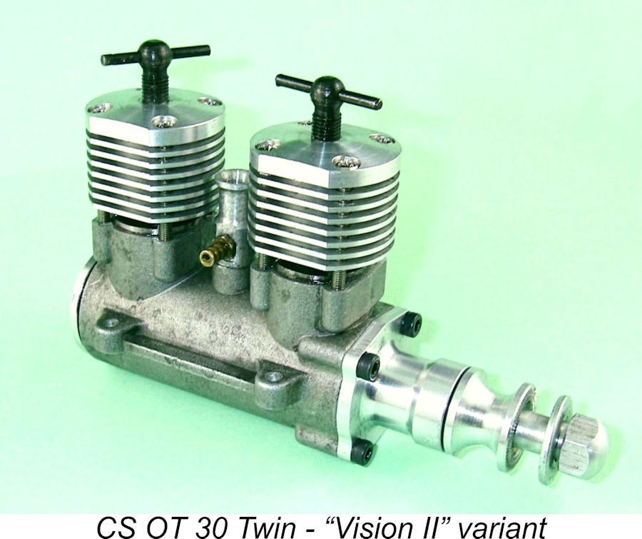
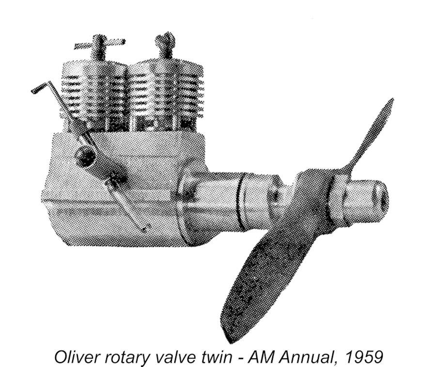 The majority of the Oliver Twins used reed-valve induction, each crankcase having its own reed valve which was supplied with mixture from a common carburettor. However, at least one variant was made which used a form of rotary valve induction. Seen at the left, this unit was mentioned in an article by the late
 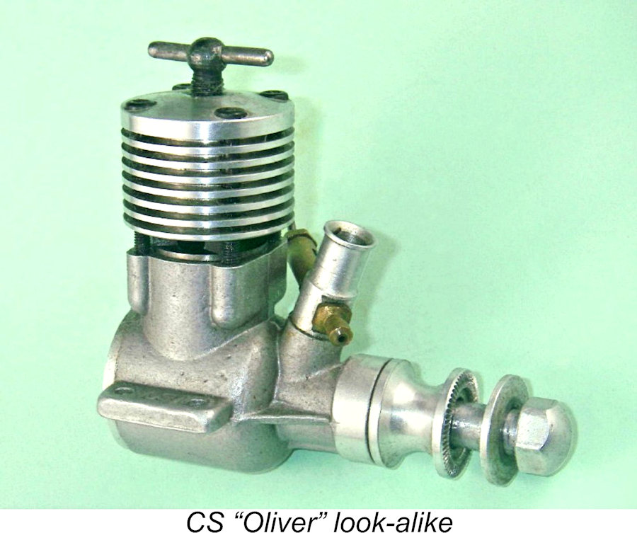 All that changed in early 2011 when the CS company of Shanghai, China, released an in-line twin cylinder diesel based on the components of their long-established CS "Oliver Tiger" 2.5 cc model. The latter engine was loosely based upon the Mk. III Oliver Tiger and found users all over the world (including myself). If well prepared, it can give a "real" Oliver a good run for its money!
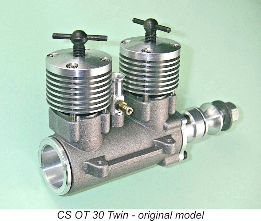 The first question that anyone asks when the subject of the CS "Oliver Twin" comes up is - how accurate a replica was it of the original Oliver Twin? The answer may be given very directly - it wasn't a replica at all! It was based on CS's own "replica" of the Mk. III Oliver Tiger, which in itself wasn’t a close replica but rather a “look-alike”. In design terms, it was quite unlike any in-line twin that the Oliver family ever produced.
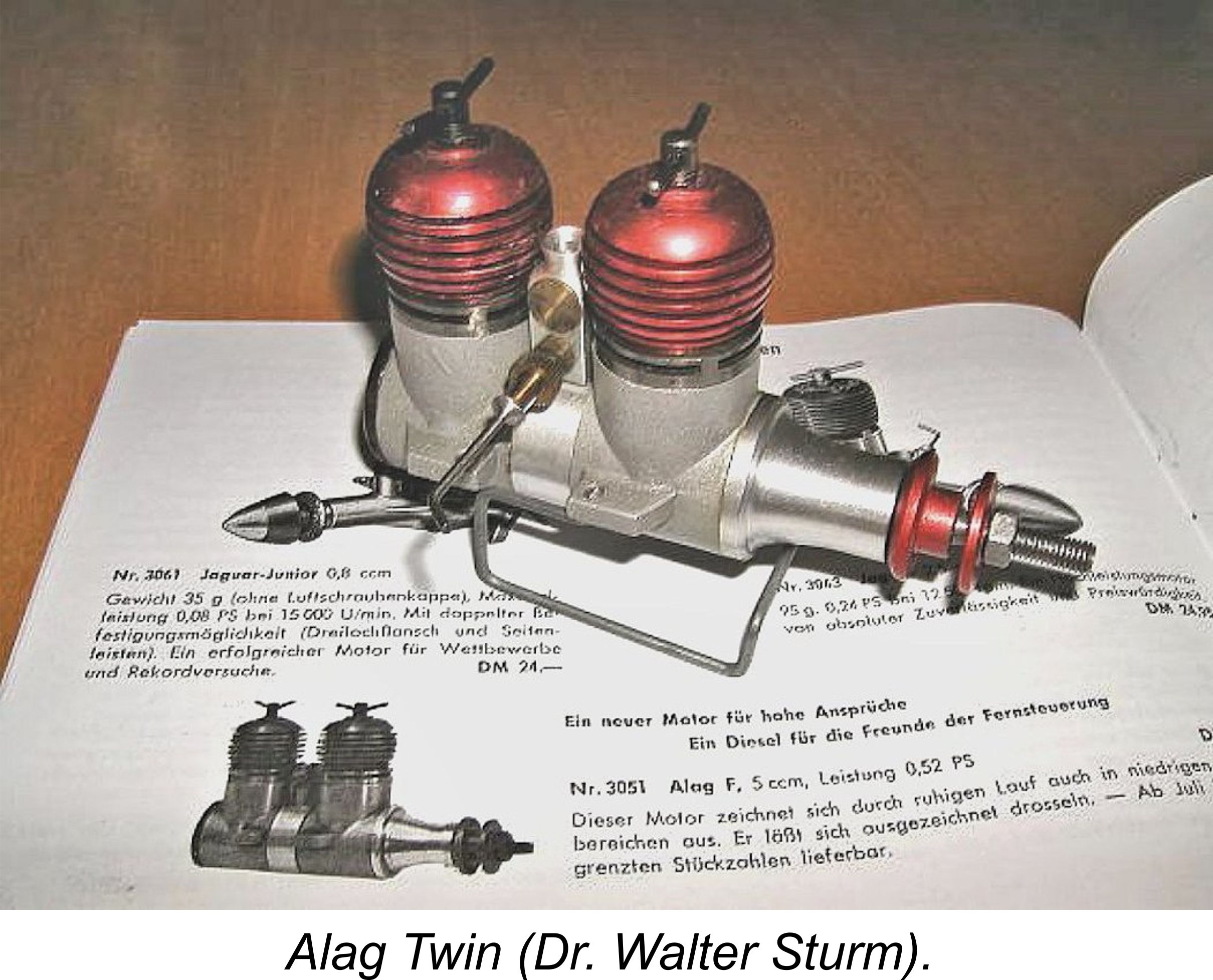
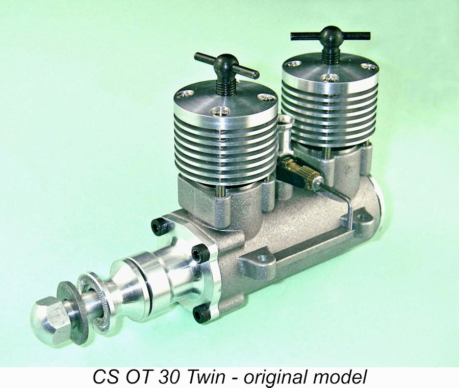
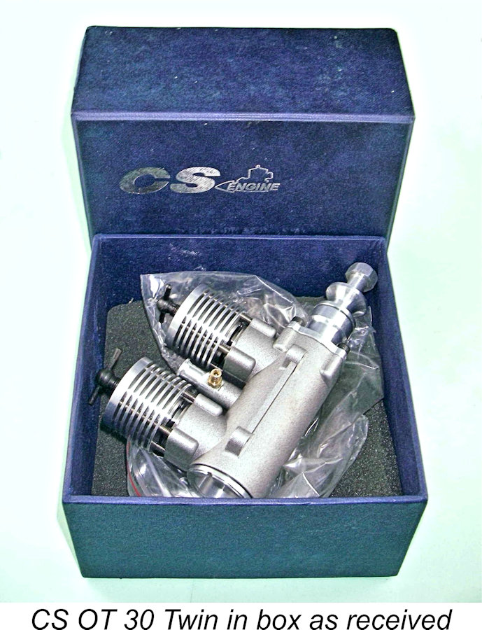 My example of the CS OT Twin 30 arrived in one of CS's standard generic blue boxes with no instructions and indeed no paperwork at all. Upon unpacking, it was immediately apparent that I was dealing here with a rotary valve design as opposed to a reed-valve unit. The engine appeared at first glance to consist of a pair of CS's standard “Oliver” piston-cylinder units mated to a common one-piece crankcase casting having a bolt-on front end and a screw-in rear backplate. Bore and stroke of each cylinder were 14.05 mm and 16.00 mm respectively for a combined displacement of 4.96cc (0.303 cuin.). The engine weighed in at 334 gm (11.8 ounces) - rather hefty for a 5 cc unit, and well in excess of the claimed weight of 210 gm posted on the CS website. Where that figure came from beats me!
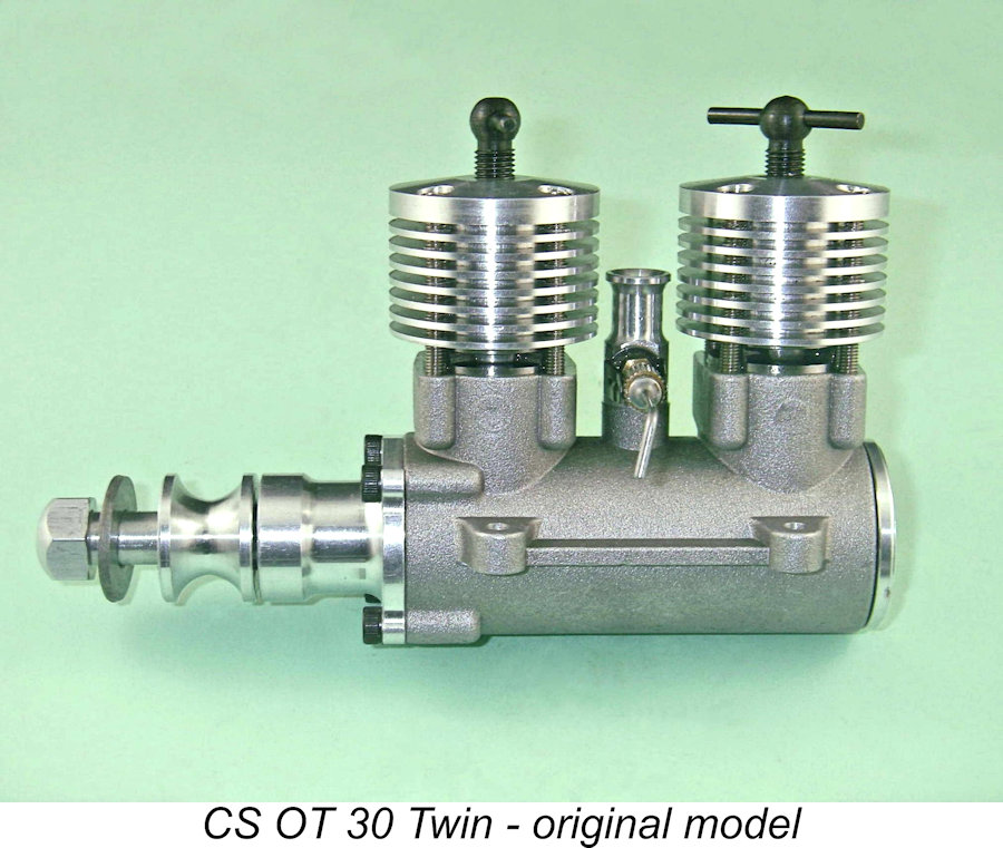
 I'll confine myself to stating that the engine came apart with no complications. It was no surprise to find a very healthy dose of shop debris inside - this is unfortunately a chronic fact of life with CS engines and explains why I wouldn’t so much as turn one over until I'd had it completely apart for a thorough cleaning. It was a great pity that CS appeared unable to get on top of this issue even after many years in production - they really should have been able to do better. They definitely improved over time in other areas - why not this one?
 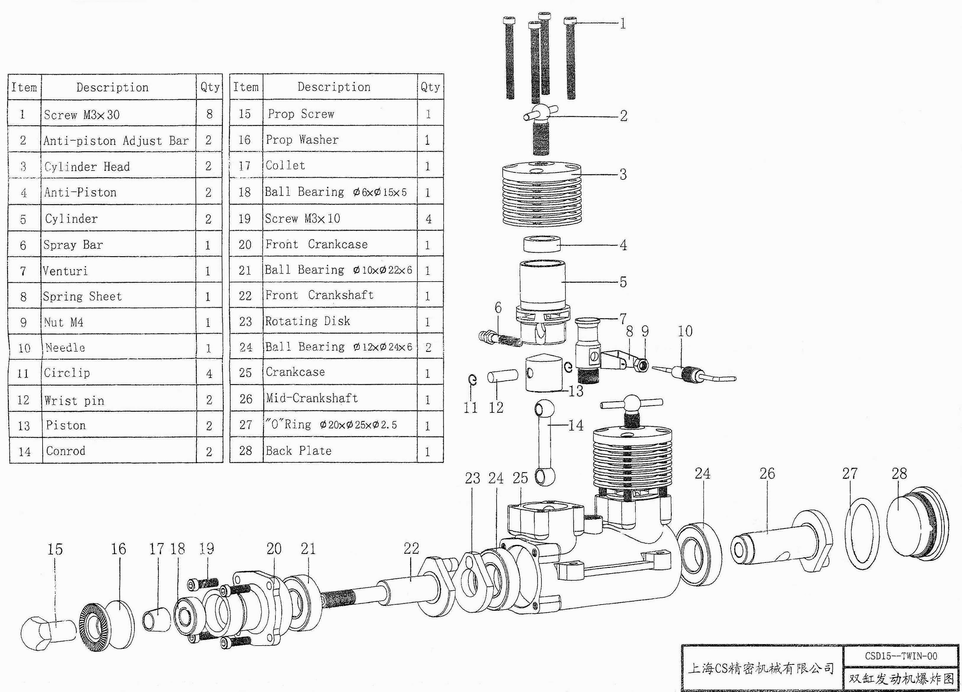 The greatest challenge involved in producing a successful in-line alternate-firing twin cylinder engine, particularly one which is supplied with mixture by a single carburettor, is that of ensuring uniform distribution of mixture between the two cylinders. As mentioned above, the original Oliver Twins mostly used reed valve induction which fed each crankcase on demand, the sole exception being their rotary valve in-line alternate firing model using a central flywheel with suitable porting. The CS Twin adopted neither of these approaches - instead, it used a form of conventional crankshaft rotary valve induction which was arranged to supply mixture to each crankcase in turn from a single carburettor.
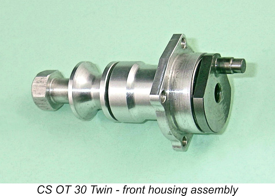 created a marked difference between the crankcase volumes for the two cylinders, which appeared problematic from a mixture distribution standpoint. Maris Dislers chose very logically to plug the central hole in his example with an aluminium alloy dowel, while I elected to test mine initially as supplied. I could always plug the hole later.
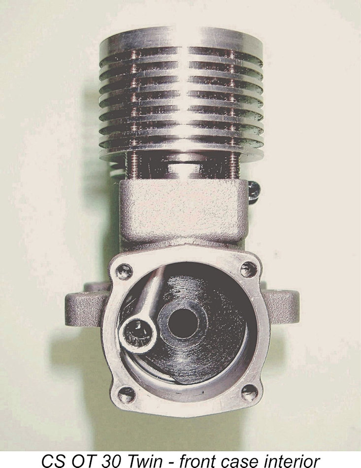 The finish of the 5 mm diameter crankpins on both shafts may fairly be described as being on the good side of adequate. There was certainly room for improvement, but the two crankpins looked as if they would be up to the job as supplied. Subsequent experience confirmed this impression, as we shall see.
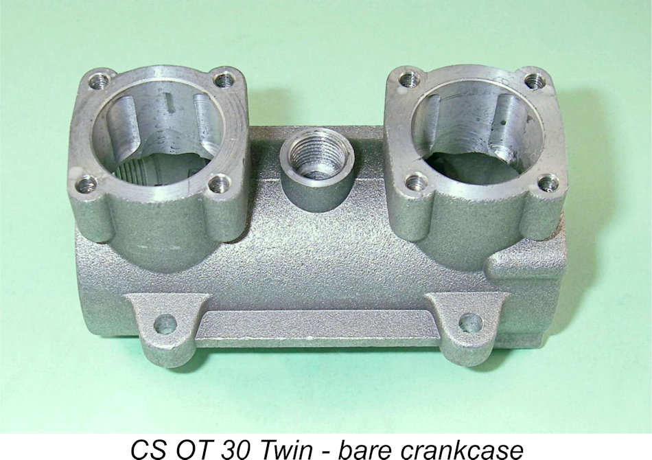 However, the incident did highlight the fact that the integrity of this joint was perhaps a little marginal and that consequently great care was required in operation, particularly as regards the handling of the compression control for the rear cylinder. Neither Maris Dislers nor I experienced any problems in this area despite putting a fair bit of high-speed running time on our respective examples - the reported failure may have been an isolated incident.
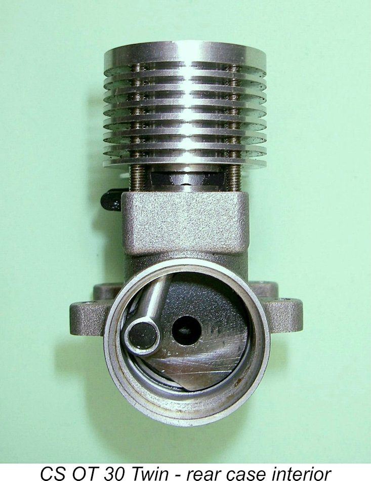
 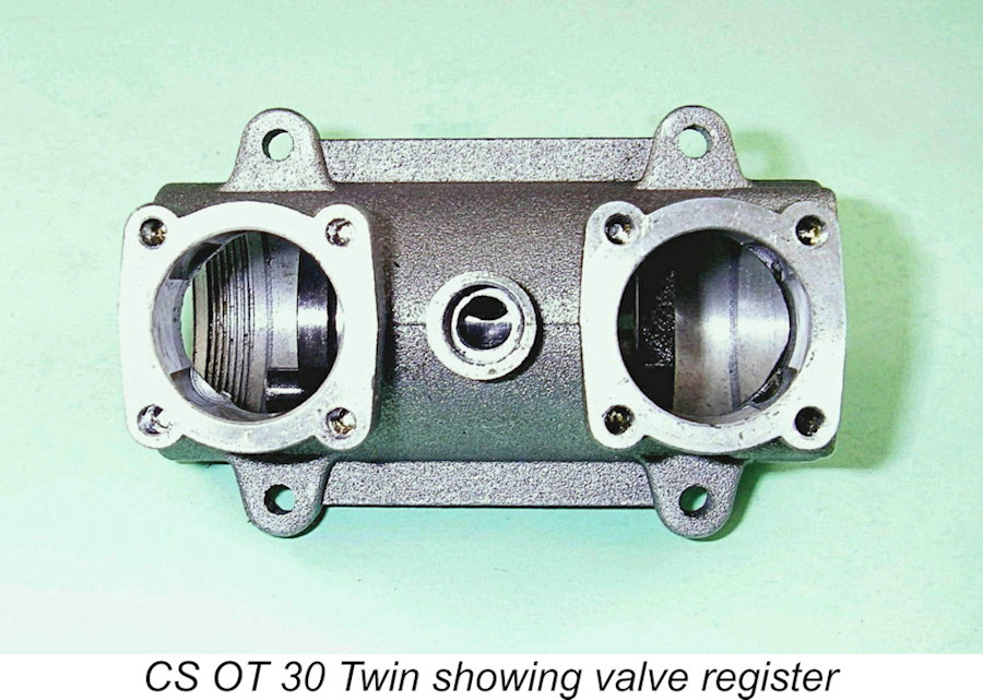 Each of the two central gas passages had its own induction port, the two ports being located 180 degrees apart on the journal circumference. The entry points into the two induction ports were axially located at the centre of the journal length so that they both corresponded to the centrally-located intake venturi section. In order to keep them communicating independently with their own internal gas passages, they were drilled at what appeared to be around a 45 degree angle towards the corresponding ends of the shaft. The points at which they met their respective gas passages appeared to have been cleaned up with a hand-held grinder prior to final assembly.
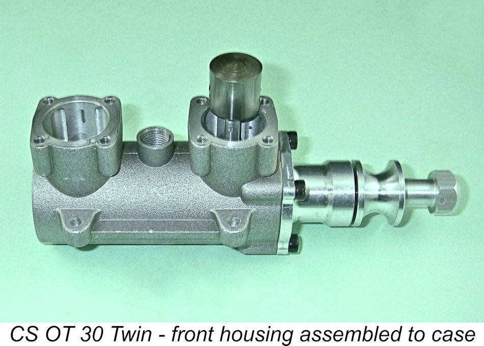 So much for the central shaft unit. I spent a great deal of time examining this feature since it was so fundamentally critical to the engine's design and operation. The rest is more simply told because the balance of the engine really amounted to a pair of standard CS “Oliver” piston-cylinder-rod assemblies being grafted onto the composite crankshaft assembly already described in detail.
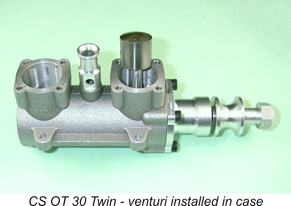 The intake venturi was most conveniently installed at this stage. It screwed into a tapped hole in the upper crankcase between the cylinder locations. When correctly aligned, it was quite tightly fitted, leading one to suspect that a measure of selective fitting was involved. Either that, or it was drilled after initial tightening and then removed for the milling of the flats on each side for the spraybar and mounting nut.
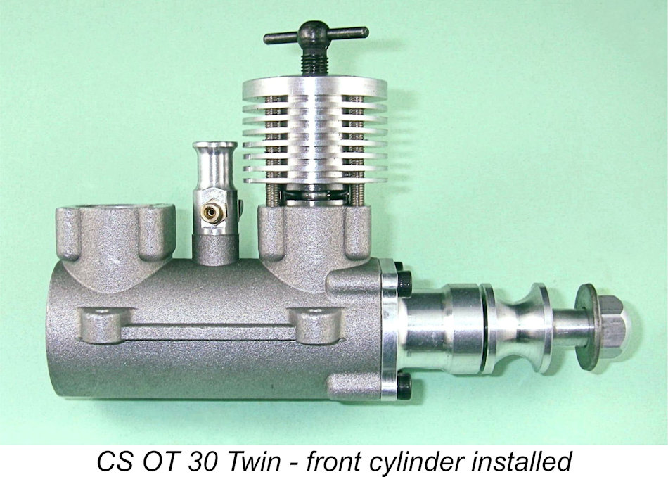
 carburetion to a degree, but the engine should run in this state nonetheless. I noted this down as an interesting possibility for later testing.
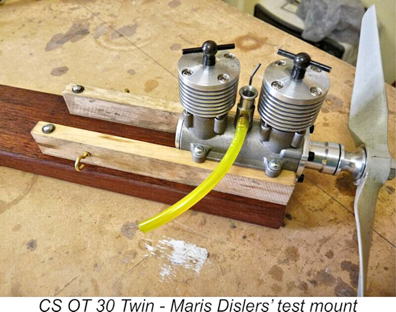 Maris Dislers was the first of the two of us to get his example of the engine onto the bench for a few test runs. Having made a test mounting as shown in the attached image and using a 10x6 Taipan prop, he was successful in getting an immediate start. All that was necessary was a “dry” prime in both cylinders.
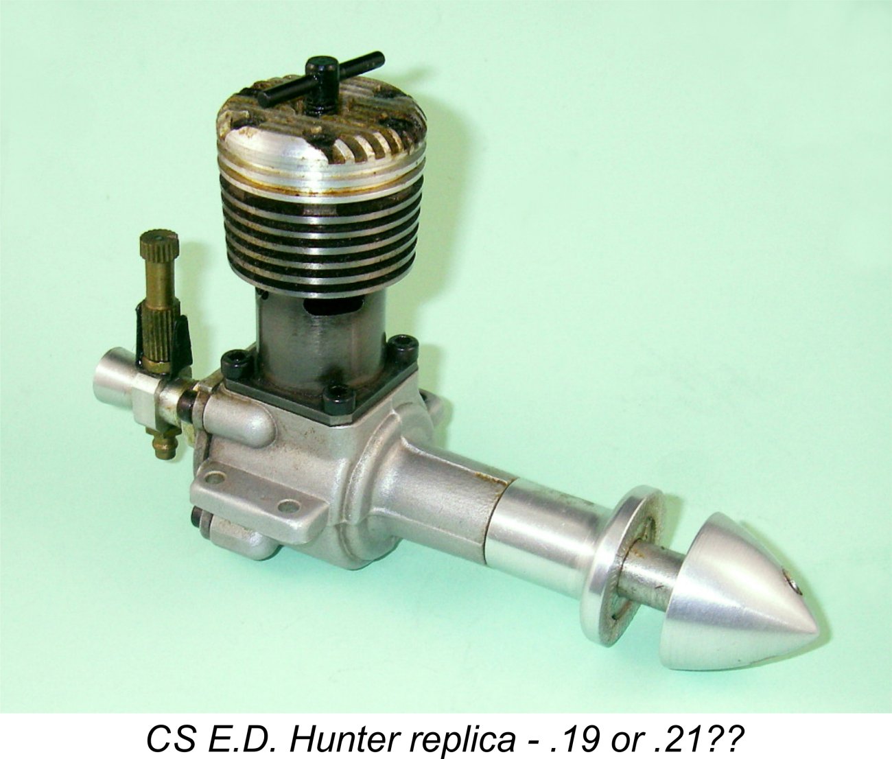 It appeared that this seizure had been caused by a combination of oil starvation due to the shielded bearings and a too-close fit between the main crankshaft journal and the plain bearing section of the housing between the ball races. CS are known for this latter characteristic - my otherwise-excellent CS E.D. Mk. IV Hunter replica seized in exactly the same manner during its break-in period. It's really a bit odd that CS didn't incorporate a small cross-drilled hole in the plain bearing section of the Twin's front journal to allow for oil distribution from the central passage in the front shaft. They certainly did so in the case of the E.D. replica, although that didn't prevent the seizure that I suffered with that model.
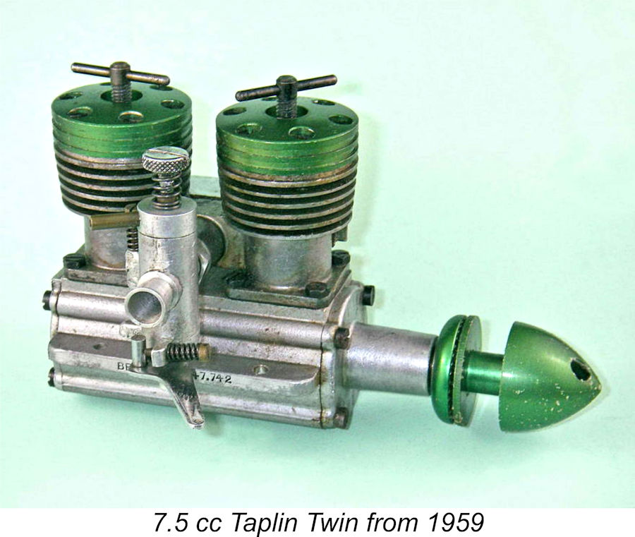 Having said this, it's only fair to point out that these are actually very impressive results indeed for a twin-cylinder diesel based upon 1950's radial-port technology. The levels of performance recorded by Maris would have been considered exceptional for such an engine at that time, being well ahead of such highly-regarded twins from the late fifties and early sixties as the sideport Taplin Twin diesel and the twin rotary-valve D-C Tornado glow-plug model. Even the previously-mentioned 1958 Alag 5 cc twin which appears to be the nearest thing to a true predecessor in design terms only produced a factory-claimed 0.51 BHP at unspecified RPM.
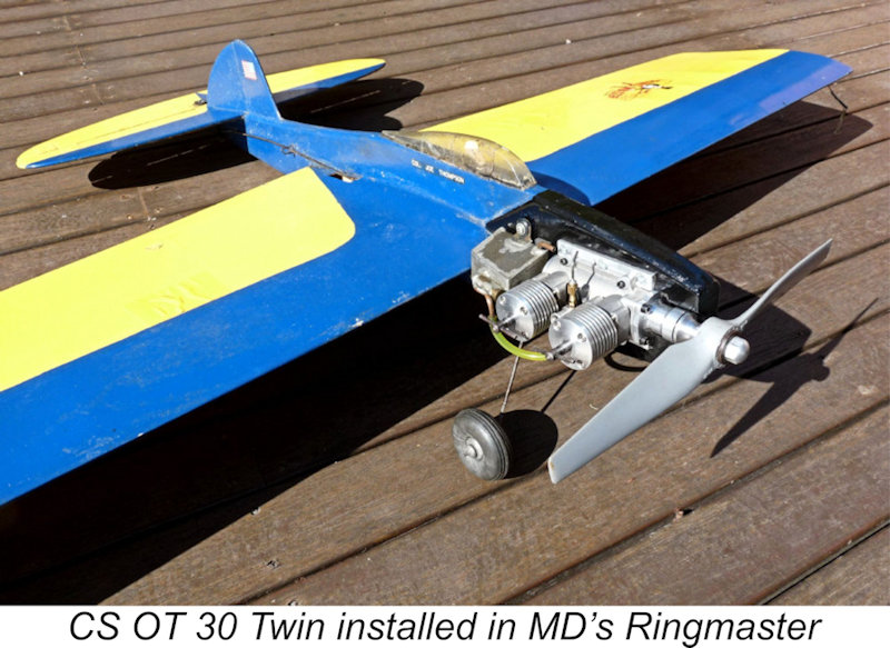 Maris proceeded to put his money where his mouth was by shoe-horning his modified CS OT 30 Twin into an old Sterling Ringmaster control line stunt model which he had lying about. The engine was mounted on two metal plates which were permanently glued and screwed to the model. Because of the substantial weight of the OT 30 Twin, Maris had to fit a 50 gm tail weight to get the balance point somewhere near correct.
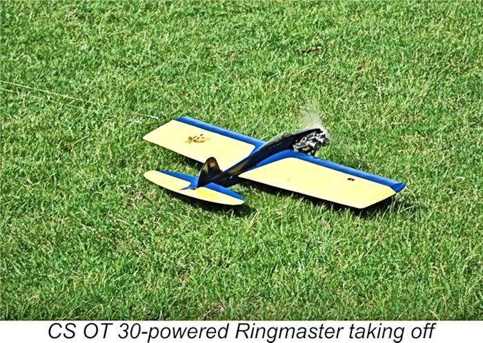 On air-testing the model, Maris found that the OT 30 Twin flew the model very well using a Magnum 10x5½ airscrew, which is probably as big a prop as the engine could reasonably use with this very heavy model. Maris felt that a 9x6 might allow it to go through the turns more easily. Even so, the model was able to get through the complete Old Time Stunt schedule with no problems. The engine started every time with one or two flicks, also performing very well in the air. Vibration was found to be quite low - about what would be expected from a typical 2.5 cc single cylinder engine.
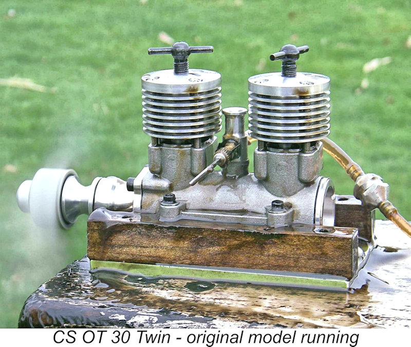 Turning now to my own example, I found the rebuilt engine just as easy to start as Maris had done. Once the settings had been established, a small dry prime in each cylinder... a few flicks... and away she went. Unlike Maris's engine, the front contra-piston proved to be perfectly fitted while the rear contra was perhaps a little tighter than ideal, but not excessively so.
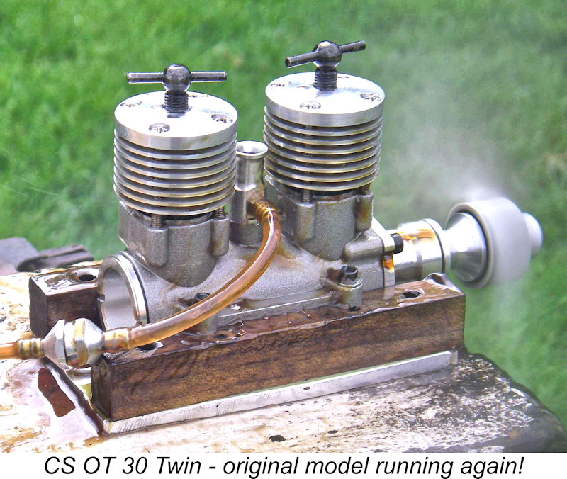 I considered following Maris's lead by making two new rods of 1 mm greater length than standard, but decided in the event to stay with the stock length so that it would be possible to get some idea of the effectiveness of this modification through a comparison of test results between our two engines. For the same reason, I elected not to plug the central passage in the front shaft as Maris had done, even though I believe this to be a promising approach - I could always try the effect of this modification later. My engine went back together (for the second time!) in its original design configuration as supplied apart from the fact that I had removed the shields from the front shaft ball-races and had also relieved the plain bearing fit for that shaft.
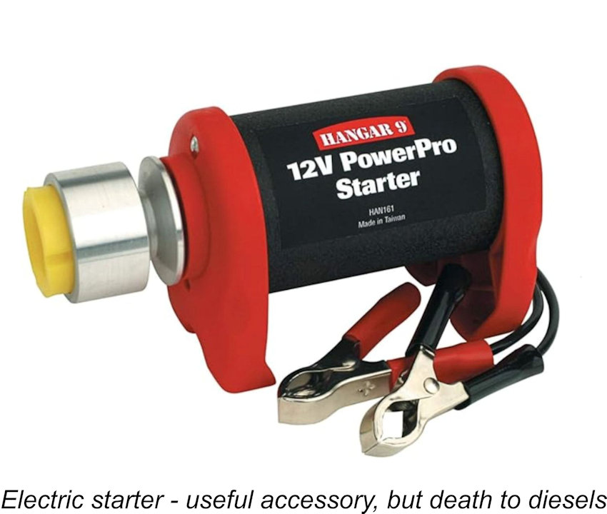 Second, we have to accept the fact that mixture distribution between the two cylinders is highly unlikely to be absolutely uniform. This being the case, we want the mixture to be at the optimum setting for the leanest-running of the two cylinders. It's far better to have one spot-on and the other slightly rich than it is to have one correct and the other too lean.
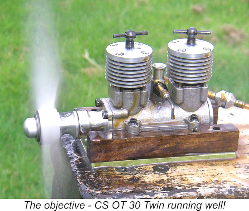 After a few rounds of this, you should have the engine running more or less misfire-free on both cylinders. Then it's a matter of fine-tuning. Here's where the eyes come in! To find the optimum leaned-out needle setting, screw in the needle until a misfire is heard. One of the cylinders will almost certainly go lean before the other. Which one can readily be determined either from the puffs of white smoke which the lean cylinder will emit or by feeling for the erratic exhaust emissions with a finger-tip (not too close!). Then pull out the needle just a fraction past the point at which the misfire and smoke vanish, and that should be your optimum leaned-out setting on the prop in question. The fact that the other cylinder will be slightly rich in this condition doesn't matter - far better this way than having one pot running lean!
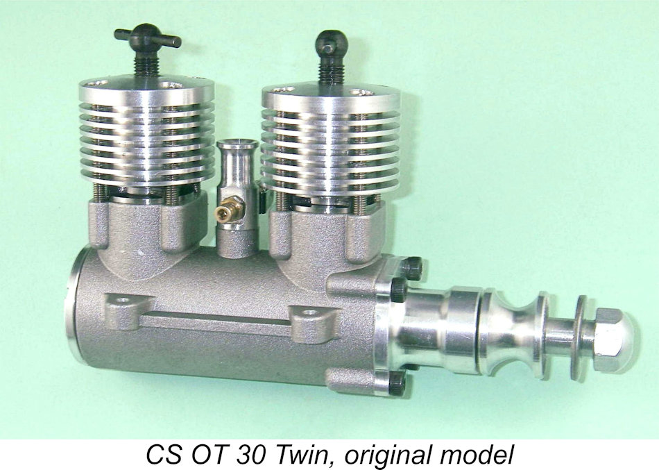 I thought long and hard about the best way to sum up our experiences to date with this engine. I didn't want to be unfair to CS, whose ongoing efforts to bring us useable replicas of classic model engines had been very sincerely appreciated. However, I also had to consider the interests of my fellow model engine enthusiasts who might be considering the acquisition of one of these units. They deserved to be accurately informed regarding the challenges which this engine could undeniably present.
 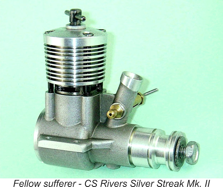 In terms of quality control, it appears on the basis of this showing that CS still needed to improve in two areas - inspection and cleanliness during assembly. Deficiencies such as the too-short gudgeon pin in my engine really should not get past the inspection process. This was not an isolated case either - one of my CS Rivers units (which proved to be an excellent engine after sorting) had a similar problem as received. Moreover, there is absolutely no excuse in this day and age for the amount of shop debris which was to be found in every new CS engine of my personal acquaintance (and I’ve had a few – I was a good customer!). I have no doubt at all that CS could (and therefore should) have done far better in this respect.
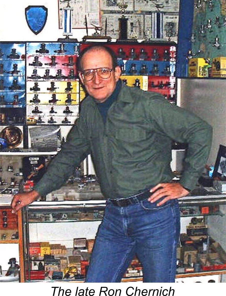
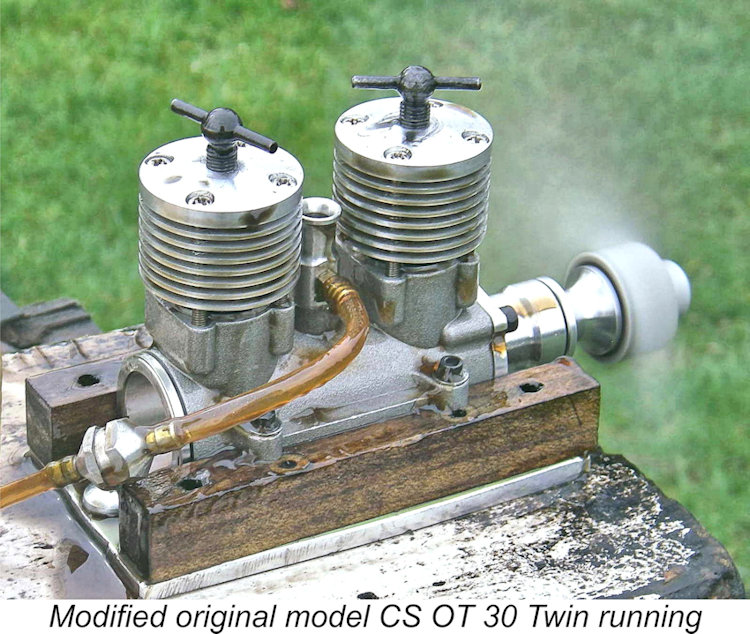
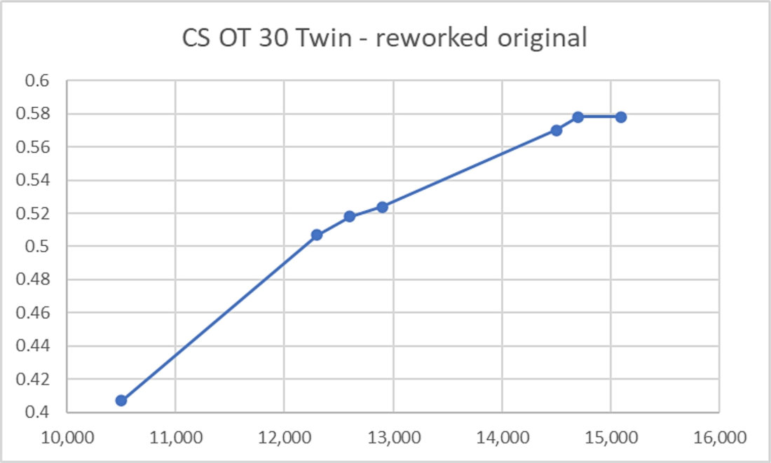
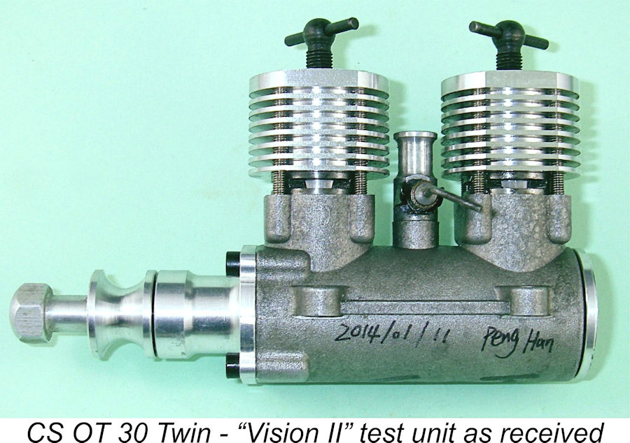 As mentioned way back at the start of this article, it turned out that CS were following our efforts with great interest! They read the original version of this article with close attention, taking note of our suggestions for improvement of the design. The result of their deliberations was the development of what they called the “Vision II” version of the OT 30 Twin.
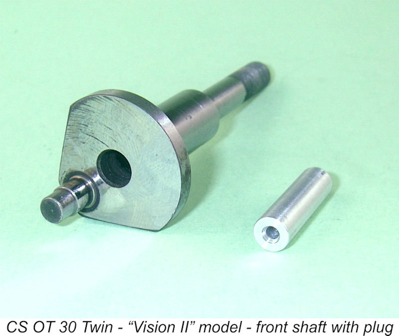 Indeed, contact with CS during the course of this evaluation suggested that they were indeed receptive to the idea of giving this a trial. They undertook to send me an aluminium plug which they felt would have the desired effect of reducing the volume of the front crankcase. They requested that I test the effectiveness of this modification, which I agreed to do. It duly arrived and was installed prior to my testing of the Vision II engine.
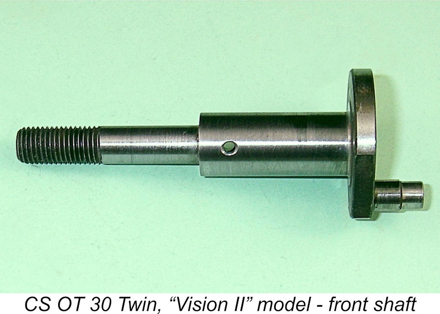 The fit of the central plain bearing section of the front shaft appeared to be noticeably slacker that it was formerly, again as per our recommendations. Although this test engine had clearly done some running, there was no visible trace of any metal-to-metal contact on the main journal surface of the front shaft.
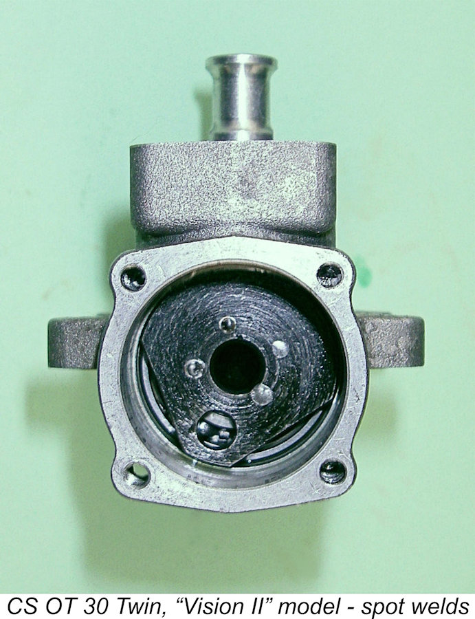 The central crankshaft looked pretty much identical to that of the original model in terms of its design configuration. The one immediately-visible change was the addition of four small spot-welds more or less uniformly spaced around the junction between the forward end of the central shaft and the intermediate crankweb. While this should certainly help to minimize the possibility of slippage occurring, the heat involved could potentially affect the metallurgy of the component as well as that of the bearings. Our preference would be for the use of a Woodruff key or similar along with continued use of a tight press-fit to eliminate fretting. I learned from CS that they were considering the use of such an arrangement for the next version of the engine (the “Vision III” model) on which they were already working.
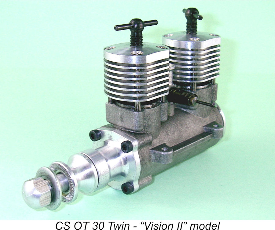 The difference was of course attributable in large part to the extra volume of the front case caused by the presence of the central hole in the front crankshaft, which was still unplugged when I performed this test. There seemed little doubt to me that filling the central hole in the front shaft would be a very worthwhile step in terms of equalizing the distribution of mixture between the two cylinders. As mentioned earlier, this modification was subsequently added to the engine prior to testing.
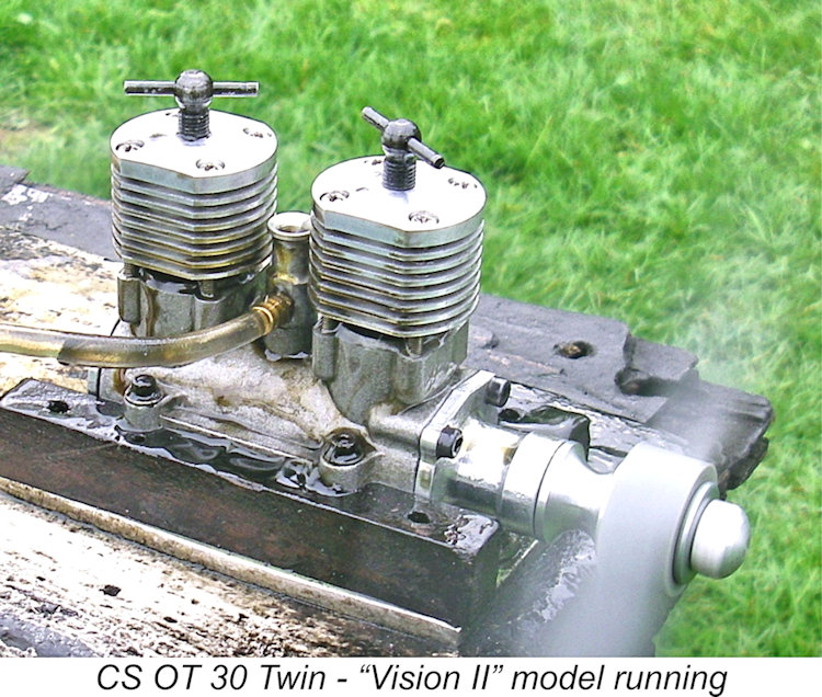
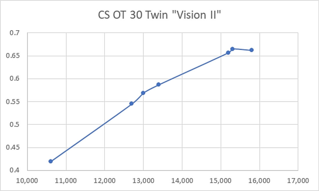
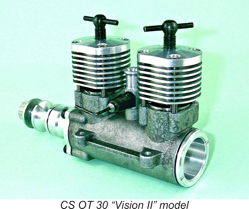 It's also a notable fact that the Vision II engine required no intervention whatsoever on my part beyond the installation of the plug in the front shaft. No mechanical issues of any sort were encountered either during the break-in process or in the course of a hard test session. Well done, Peng Han and Co.!
 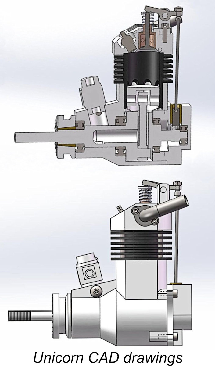 In early July of 2018 I heard again from Peng Han. He told me that he had been unable to stay away from model engines and was in the process of developing a new design called the “Unicorn” to be marketed by a new company. This unit was designed to a most unusual configuration – a valved two-stroke engine! As far as I know, this was the first attempt anywhere to develop such a unit for model applications.
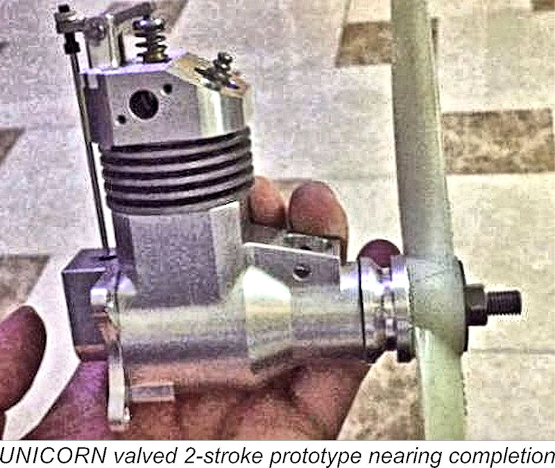 This was by no means a new design approach for an internal combustion engine. Large full-sized two-stroke
 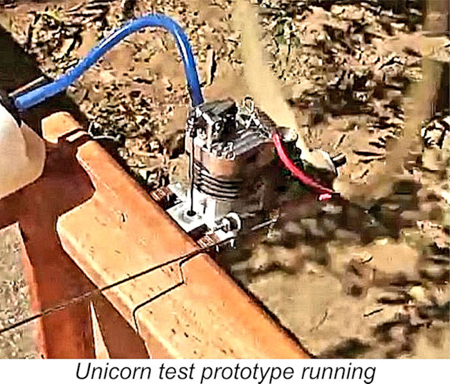 Peng told me that the intention was to develop a diesel version of the Unicorn. In early December 2018 he advised that the testing process had revealed a number of required modifications. These included optimization of the timing as well as beefing up the strength of the valve pushrod and the conrod. Possible material changes to the piston/cylinder combination were also under review, presumably with a view towards weight reduction. The first prototype had been disassembled and the process of modification started. A particular concern was the creation of a suitable R/C carburettor – the one fitted to the prototype had failed to meet expectations.
 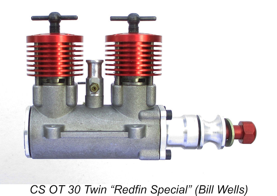 Following the initial publication of this revised article, my English mate Bill Wells was kind enough to send along a few images of a previously-unrecognized OT 30 Twin variant. This was apparently an example of the original model which lacked the Vision II's trimmed cooling jackets but made up for this by sporting cooling jackets and a spinner nut which were anodized red. It also bore a serial number - in Bill's case, no. 015. Bill purchased this engine in the October 2023 BMFA auction.
 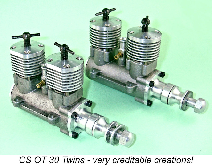 If you just want one as a collector's piece for display purposes, go ahead and try to find one - it's a great-looking item which is an unusual collectible. If on the other hand your ambitions include actually running the thing, then I'd have to qualify my answer rather heavily - by all means go ahead and acquire one as long as you're confident of your own technical ability to deal with issues of the kind raised in the above report. Above all, do not buy a new example of this engine expecting it to run well for you straight out of the box! At the very least, you'll have to take it apart and rebuild it following a thorough inspection and cleaning. Bear in mind also that spare parts are no longer available.
| |