
|
|
The AMCO .87 Diesel
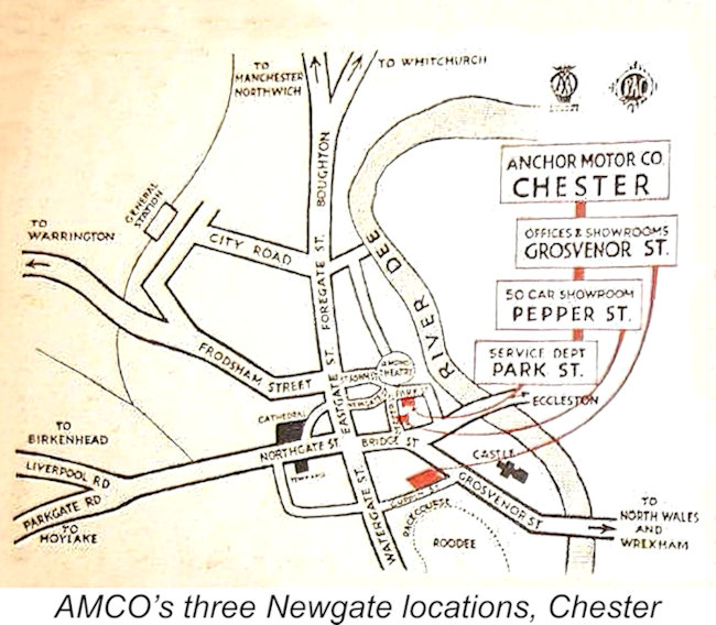
This article is a comprehensive reworking and expansion of my original September 2007 piece on the AMCO .87 Mk. I which may still be found on the late Ron Chernich’s “Model Engine News” (MEN) website. Unfortunately, Ron left us in 2014 without sharing the access codes for his heavily-encrypted site. Consequently, no maintenance has since been possible, the result being that the site is now showing unmistakable signs of deterioration as time passes. It is for this reason that I’ve been transferring many of my earlier MEN articles over to my own site. In the present instance, I’ve taken full advantage of the opportunity to re-organize and augment the material quite substantially while also correcting a number of errors. Rather than being a straightforward transfer, this is a completely new article. As always, I’ll begin my evaluation of the AMCO .87 with a little background. Here goes ……… Background The AMCO range of model engines was the creation of the Model Engineering Division of the Anchor Motor Company, who gave their address as The Newgate, Chester, Cheshire, England. Before going any further, I should point out that the company’s trade-name is correctly rendered as “AMCO”, not “Amco”, since it The company had been founded in the 1930’s as a firm of automotive engineers, thus having much in common with the contemporary North Downs Engineering Co. of Whyteleaf in Surrey, makers of the 10 cc Nordec racing engines, in that their primary business related to full-sized automobiles. In both instances the model engine manufacturing was a sideline, evidently added because of an interest in modelling at the management level. The Anchor Motor Company grew into quite a large organization, employing up to 80 staff during its heyday. They were engaged in car sales (Standard, Riley, Hillman, Humber, Thames and Rootes over the years) as well as operating a major vehicle servicing facility which included both a spray shop and a very extensive machine shop. They were deeply involved in motor engineering, including servicing, rebuilding and re-boring a variety of engines, both automotive and commercial (Perkins A pre-war Anchor Motor Co. promotional booklet discovered by my friend Jim Woodside yielded further details regarding the company’s operations during the 1930’s. As shown on the attached map from the booklet, the company had premises at three different locations. The offices were located on Grosvenor Street, with a small showroom on the ground floor. There was a far larger showroom having space for 50 cars on nearby Pepper Street, while the service department was located round the corner on Park Street (in effect, a continuation of The Newgate opposite). It may appear odd that the address of the company was given as The Newgate, since none of its premises It’s worth noting at this point that the machine shop itself did not share accommodation with the rest of the operation at The Newgate, but was separately located on Victoria Road in the outskirts of Chester to the north. It was presumably at that location that the model engines were subsequently made. During WW2 the company engaged in the renovation of lorry (aka truck) and car engine parts, limited during that period to vehicles in essential national service use. They did re-bores and re-sleeving, reground camshafts and crankshafts, re-ground heads, restored brake-drums (skimming and re-lining) and re-lined clutches, among other things. They also applied their expertise to the production of components for Wellington and Lancaster bomber gun turrets as well as tail units and wiring harnesses for the legendary Spitfire fighter. They must have been busy!
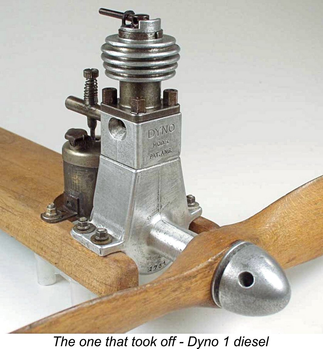
According to the recollections of the late Ted Martin as related to Jim Woodside, the AMCO model engine range had its genesis in the fact that following the end of WW2 the Managing Director of Anchor Motor Co., Bill Leeman, bought a Swiss Dyno model diesel for his son. Leeman took a good look at this engine and realized that the excellent machine tooling which the company had at its disposal could well be turned to commercial advantage in manufacturing a similar product. Once they had decided to enter the model engine manufacturing business, a decision which they evidently made in 1946, the company had to come up with an appropriate design for their first commercial offering. They had no design or manufacturing experience of their own with model diesels, which were in any case very much in their evolutionary stage at the time in question – the first British-made commercial model diesels hadn't begun to appear until mid-1946. Accordingly, the idea of adopting someone else's established design would have had considerable attraction for them at the outset.
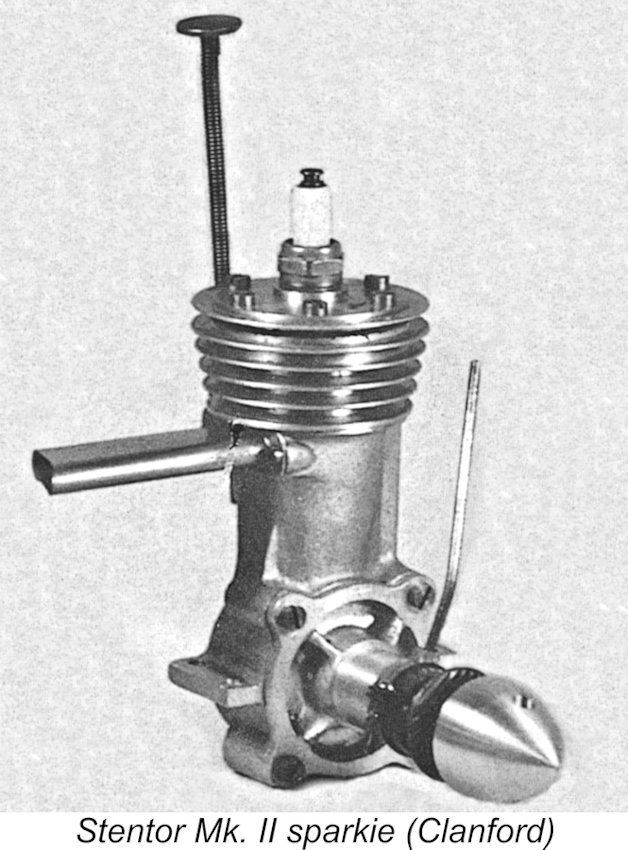
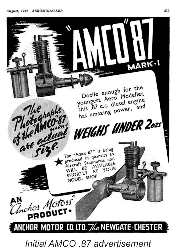
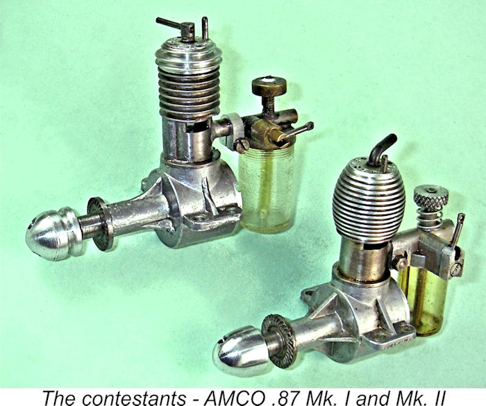
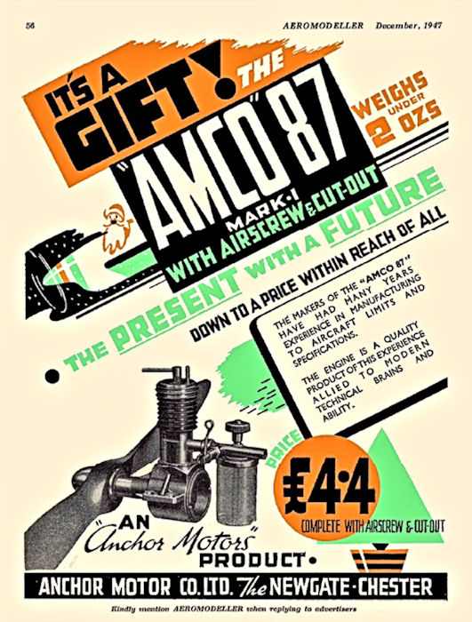
Having somehow learned about Healy’s efforts, the Anchor Motor Co. approached Healy with an offer to purchase his design for series production in Chester. Healy accepted their offer, the result being that the rights to his The initial prototypes of the AMCO .87 were very similar indeed to the Healy Midge from which the engine was derived. The “Healy 1.2 cc” diesel shown on page 93 of Mike Clanford’s well-known but often misleading “A-Z” book is actually an AMCO prototype - the case says as much. The resemblance to the original Healy design is quite striking. Probably because they still lacked the appropriate in-house expertise, the company encountered some manufacturing challenges in preparing to put this engine into series production. Their response to this This advertisement was brought to the attention of 25-year-old E. C. “Ted” Martin, who immediately jumped at the chance, becoming the Anchor Motor Co.’s resident model engine design and production expert. Ted had plenty of relevant experience, having designed the well-known Stentor 6 cc petrol engine for Rogers and Geary of Leicester, who had previously made the pre-war Spitfire 2.5 cc petrol engine as well as the British Wasp and Hornet sparkies. The Stentor was quite successful, appearing in two successive variants and being sold primarily through the Bournemouth Model Shop, where the late Phil Smith achieved so much in terms of model design work under the Veron banner, including the Stentorian design which was created especially for the Stentor. Following Ted Martin’s arrival, the initial production difficulties were progressively sorted, the end result being the company’s first commercial product, the AMCO .87 Mk. I. The first advertisement for this model appeared in the August 1947 issue of “Aeromodeller”, as reproduced at the left. The market prospects for this engine doubtless appeared to be very good, because the little AMCO faced minimal competition in the under-1 cc displacement category at this time. The engine's introductory selling price was £4 4s (£4.20) – this was prior to the general reduction in model engine prices which was stimulated by the subsequent arrival of the E.D. Bee and the FROG 100. It’s interesting to note that the manufacturers themselves referred to their new offering from the outset as the AMCO .87 Mk. I, clearly implying their expectation that an improved Mk. II version would be forthcoming at some point. For reasons which must forever remain unclear, the Anchor Motor Co. used their own company name in connection with this initial offering only. Thereafter, they always identified their engines as products of Anchor Motors rather than the Anchor Motor Co. My good friend Marcus Tidmarsh was unable to find any evidence to suggest that Anchor Motors was ever a formally registered company. It may simply have been a “flag of convenience” used solely in connection with the company’s model engines. It certainly slides off the tongue more easily than Anchor Motor Company! Now let’s have a closer look at the engine which gave the Anchor Motor Co. a good start in the model engine business. The AMCO .87 Mk. I
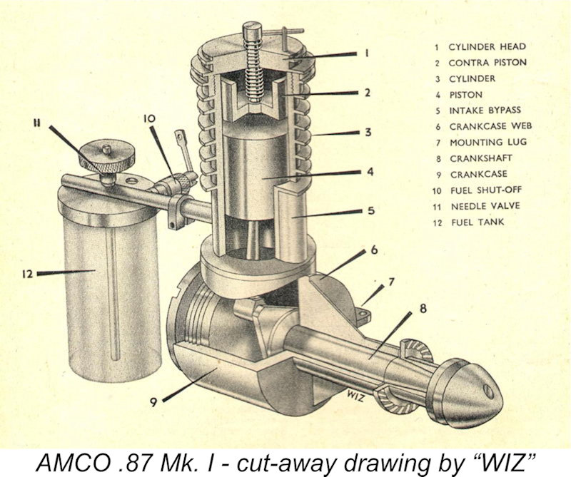
Reference to the accompanying component view of the engine from the AMCO instruction leaflet will help to clarify the following The aluminium alloy cylinder head was internally threaded, screwing onto an externally-threaded spigot at the top of the cylinder. The numbers on both the cylinder head and needle valve grip were clearly intended to allow the user to record the best settings for starting and running. The compression stop pin could be set in any one of four positions once the correct setting had been found. Another very interesting and unusual construction feature was the fact that the engine featured a screw-in cylinder despite the fact that there was only one "correct" position for the cylinder when tightened down. Thankfully, Ted Martin clarified the approach taken to deal with this issue in conversations years later with Jim Woodside. The sequence of manufacturing operations was as follows:
Again somewhat unusually, both piston and cylinder were made from hardened S.14 steel. Such a hard-on-hard combination can be problematic, as the makers of the J.B. range were later to learn to their cost. The issue is that running-in wear is minimal, making it imperative that the engines be assembled with perfect running fits from the outset. This magnifies the requirement to work to extremely close limits when fitting pistons to cylinders. The one upside is that if correctly fitted at the outset, the piston/cylinder fit should easily outlast the rest of the engine. Generally speaking, the AMCO manufacturers appear to have met this challenge very well – the fits on all the examples that I’ve ever encountered personally in the metal have been beyond reproach. Apart from the idiosyncracies described above, the construction of the AMCO .87 Mk. I was very simple indeed. The cooling fins were turned integrally with the steel cylinder, with the previously-mentioned externally-threaded spigot being formed at the top to accomodate the cylinder head. The bypass passage was soldered onto the front of the cylinder rather like that of the E.D. Mk. II, as was the induction boss at the rear. The bypass fed a single drilled transfer port of quite generous size which was angled up through the liner to almost completely overlap the exhaust. Maris Dislers was able to measure the timing figures for his example of the AMCO .87 Mk. I, arriving at the following figures: Exhaust period – 146 degrees Transfer period – 142 degrees Induction period – 130 degrees. These are quite aggressive figures for a sideport engine. We would expect the engine’s best performance to be found at relatively high revs for an engine of this type.
The conrod was mounted in an alloy carrier which screwed into a tapped blind hole in the piston interior. Reference to the previously-reproduced component view will clarify this arrangement. The design resulted in a fairly heavy piston, but trapped the gudgeon pin inside the piston with no visible boss openings. This had the benefit of preventing any possibility of the gudgeon pin protruding to foul the fore-and-aft transfer and induction ports. Warning – do not attempt to extract this carrier by using the rod as a purchase – you’ll only twist the rod! A special tool is called for. Best left alone unless disturbance is absolutely necessary …………. This form of composite piston construction was later abandoned in favour of a more conventional arrangement. The one-piece steel crankshaft looked a bit flimsy - check out the cutaway view reproduced a few images below. The crankweb was rather insubstantial, but experience has shown that it seems to hold up all right in this rather low-powered long-stroke design. The web was cut away on the crankpin side to provide some counterbalance. The shaft design in the later variants was amended to a full-disc crankweb with no counterbalance – a somewhat stronger configuration.
The brass induction tube was clamped into the bore of the induction boss by a small aluminum clamp which can be seen clearly in the photos. It was a simple matter to re-set the tank to accommodate different mounting orientations. The carburettor was constructed from a number of separate brass components which were brazed onto the induction tube while mounted in a jig. As we shall see, a switch was later made to a cast component requiring no brazing. The engine featured an unusually deep tank made of injection-molded plastic. The upper portion was externally threaded, engaging with a shallow female thread inside the tank top. On the test bench, this tank resulted in a considerable leaning-out of the mixture as the level of fuel went down, significantly increasing the head against which the engine had to draw its fuel. However, the tank was stated to have been specifically designed to supply fuel in a steep-angled climb, in which orientation the change of fuel head as the fuel level dropped would be somewhat less pronounced. The inclusion of a cut-out in the design of model diesels of the period had become very common, since such engines could no longer be stopped in flight by timer-controlled interruption of the ignition circuit – there was none to interrupt! The cut-out used on the AMCO .87 was unusual, featuring a spring-loaded plunger which effectively blocked the intake tube on the engine side of the fuel jet, thus starving the engine of mixture as opposed to merely cutting off the fuel supply to the jet. The photos show it in the "stop" position. When the arm is pulled out and the lever turned at 90 degrees to rest on the outer end of the cut-out mounting, the intake is clear. When the timer pulls the lever into the visible slot, the plunger snaps home and stops the engine. Quite effective! The company went to the trouble of applying for a Patent for this device.
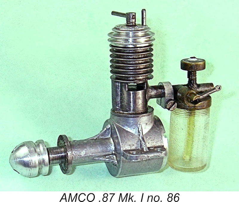
The twin prongs at the left-hand end of the illustrated factory multi-tool align with two of the holes on the cylinder head to remove it if required. The rectangular "bump" in the middle fits the backplate cavity perfectly, keeping the All examples of the AMCO .87 bore serial numbers which were duplicated on both the cylinder and crankcase, since these components had to remain together as a matched pair. The highest confirmed serial number that has been reported to me for a Mk. I variant is 3873. The fact that my illustrated example bears the number 86 implies very strongly that the sequence began with engine no. 1. This seems to confirm that some 4,000 examples of the AMCO .87 Mk. I may have been manufactured in total. Overall, the AMCO .87 Mk. I may fairly be described as a well-made little unit seemingly well-suited to powering a range of small sport and scale models. Its ready acceptance by the diesel-minded British and Commonwealth aeromodelling communities is easily understood. But what kind of a performer were they getting? Let’s consider that issue next. The AMCO .87 Mk. I on Test
Nicholls reported no difficulties in hand-starting the engine. Although no power output figures were reported, the review is particularly interesting in that it confirms the widely-held impression that different examples of the AMCO .87 displayed unusually wide variations in performance. Nicholls tried three examples of the engine, finding that the speeds measured for a “standard prop” (whatever that was!) covered a range from 5,200 RPM to 6,200 RPM for the three examples. The range for an 8x4 airscrew was 5,400 to 6,350 RPM, while that for a 7x6 was 4,700 to 5,600 RPM. Evidently you paid your money and hoped that you got a good ‘un! The broad conclusion to be drawn from this is that the ultimate performance of the engine was most likely affected primarily by the as-built piston/cylinder fit. If that was right as constructed, the engine would reach its full design potential. However, if assembled initially too tight, the use of hardened steel for both piston and cylinder would result in minimal running-in wear, probably condemning the engine to working out its life with a too-tight piston and a sub-standard performance. A cast iron piston would have been a far better choice.
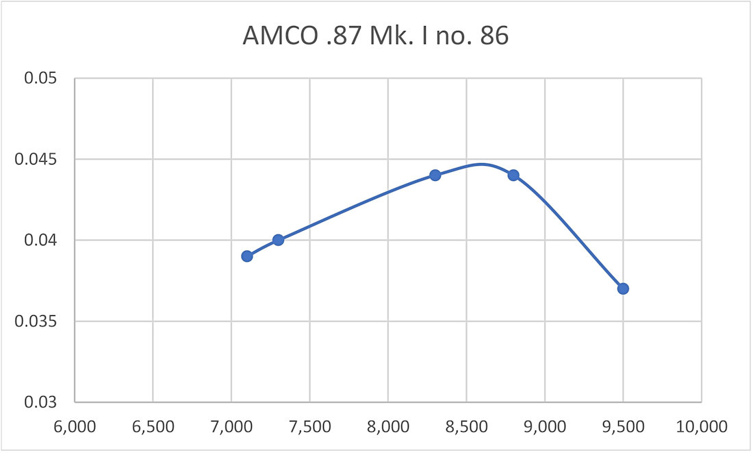
Sparey used hand starting throughout this test, finding that the engine started “exceedingly well” both from cold and hot. He reported that the AMCO ran “well and steadily over a wide range of speeds”, although the engine was said to have a tendency to “hunt” (vary its speed) at speeds above 8,000 RPM. In reality, this behavior seems to have been due to the variation in fuel head as the level in the tank went down – Sparey actually recognized this as being a possibility. Sparey reported a remarkably precise peak output of 0.0456 BHP at 8,900 RPM, which he rightly characterized as a very good performance for an engine of this specification and displacement. He commented particularly on the engine’s relatively flat power curve, with 0.04 BHP or more being available at all speeds between 7,900 RPM and 9,800 RPM. One quite insightful comment was the fact that the unusually tall fuel tank created a significant variation in fuel head throughout a run, making it difficult to establish a needle setting that would give a uniform run throughout.
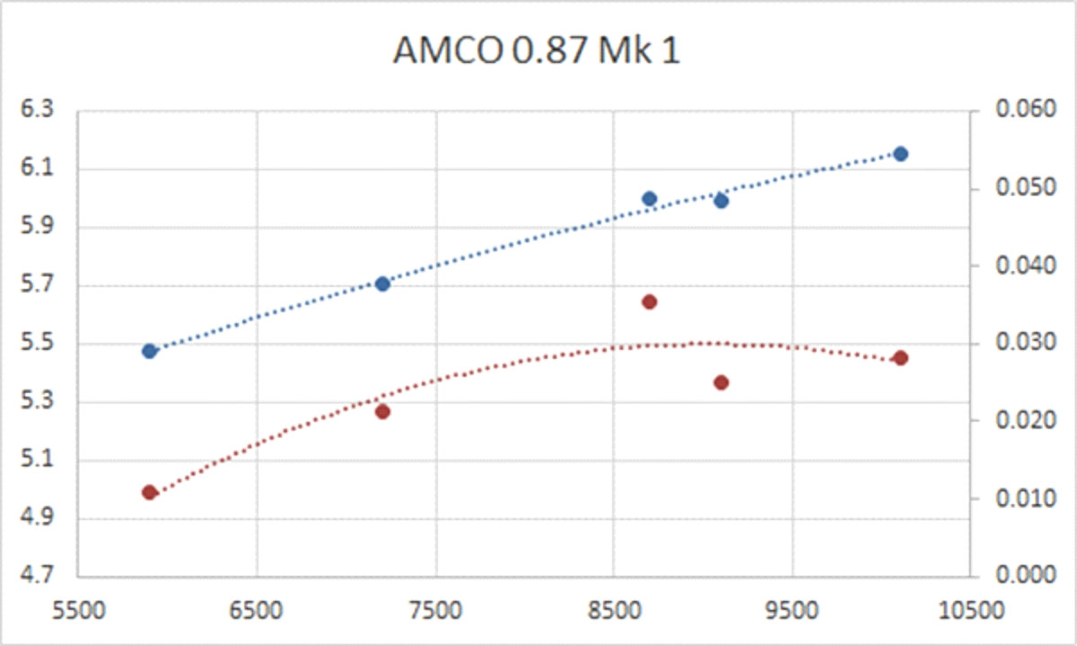
Perversely, Sparely also reported the engine’s weight as 1 ounce 15 drams!! My dictionary defines a dram as 1/16 of an ounce avoirdupois weight (the old British and US system of weights for commodities other than gems, precious metals and drugs). Even as long ago as 1948, few average British aeromodellers would have been familiar with this unit. Someone must have jumped on Sparey for using this rather obscure unit of measurement, since we find him from Engine Analysis Number 5 (the ETA 5) returning to the use of more conventional fractions or decimals! My example weighs in at a whisker over 2 ounces (58 gm) - near enough to Sparey’s figure. This is a very light weight indeed for a tank-equipped diesel of 0.87 cc displacement, being achieved in large part through the elimination of any ancillary weight such as screws, nuts and bolts. Sparey had trouble with the cut-out, which he claimed to be ineffective above about 9,000 RPM. For my part, I simply cannot see how Sparey managed this - on my examples the cut-out blocks the induction tube almost completely when activated! If the engine was running leaned-out at over 9,000 RPM before the cut-out was activated, it certainly would not be doing so after the cut-out was tripped! In fact, the cut-out on my examples works fine at all speeds tested, although its action is admittedly a little It’s an odd fact that Sparey often had trouble with cut-outs refusing to operate at the higher speeds - this is by no means the only example of him reporting that difficulty. Nicholls had not experienced any trouble, characterizing the operation of the cut-out as “positive”. A leak at the connection between the carburettor assembly and the cylinder's induction boss would certainly impair the cut-out's performance - perhaps that was Sparey's problem. Having run my own illustrated example no. 86 in the past, I can confirm that it starts and runs very well indeed. It has been used, but remains in near-perfect mechanical condition. An 8x4 prop seems to suit it quite well, and it turns an 8x4 APC glass-fibre nylon prop at a steady 7,100 rpm on the bench – around 0.039 BHP at that speed. The 9x4 recommended by the makers (according to Sparey) would have over-propped it very seriously unless a very "fast" prop was used. See below for a latter-day test of this engine. I can confirm Sparey’s comment about the fuel tank head issue - to run the tank out at the same setting, you have to set the engine so that it runs at minimum lean near the end of the run, which means that the first part of the run is inevitably slightly rich. But this would be of little practical consequence in the kind of situation (small sport free-flight models) in which this engine would have generally been used. Furthermore, the tank simply screws into the metal tank top, thus being easily removed if desired to allow the use of a separate tank. I’m very fortunate that all of my examples still have their original tanks! A Further Test by Maris Dislers At the time when I was engaged in revising this article for publication on my own website, my valued Aussie mate Maris Dislers had just acquired an example of the AMCO .87 Mk. I from the collection of fellow Aussie Anthony Williams. This example bears the serial number 2170. It was missing its fuel needle, for which Maris made a replacement. Once having got the engine into running order, he proceeded to give it a test. The engine was found to be an easy starter with a small exhaust prime. Its running characteristics were a bit odd, likely due to the fact that although it appeared to have seen plenty of use in a previous life, it still seemed to be a little on the tight side. On certain loads it displayed a tendency to overheat and sag – not all that unusual with engines featuring a tighter-than-ideal hardened steel piston/cylinder combination. Given the steel-in-steel piston/cylinder combination, further running would probably do little if anything to alleviate this condition. Even so, the engine sang like a bird with other props. Consequently, the individual data points collected by Maris were somewhat scattered. Despite this, it showed considerably better than Sparey’s test example for which figures were published in “Aeromodeller” This may have been down to Sparey’s presumed use of un-nitrated fuel. Maris used equal parts of ether/kerosene/Aeroshell 100 mineral oil plus 0.8% improver. This fuel makes a significant difference in Mills .75’s, making it seem probable that it would do likewise for the AMCO. For what they’re worth, the data collected by Maris were as follows:
The relatively inconsistent response of the engine to different prop loads makes it impossible to really zoom in on an authoritative peak output figure for Maris’s engine. All that can be said is that the general trend suggests a peak in the region of 0.060 BHP at somewhere over 10,000 RPM – quite respectable! It’s also clear that loading the engine with anything larger than an 8x4 airscrew would undoubtedly squander its potential. Further Developments Overall, the AMCO .87 Mk. I was (and is) a likeable little engine which would have given very good service. It was very well fitted, although it was undeniably a bit crude in some areas. This did not prevent it from selling very well indeed following its arrival in the model shops. This provided Ted Martin with the necessary incentive to see what could be done to improve the engine.
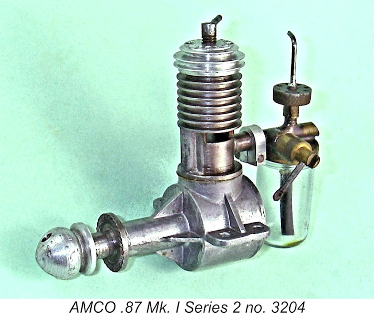
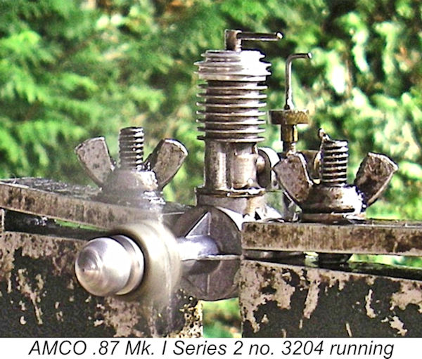
It would appear that this modification was applied fairly early on during the Mk. I engine's production life. Engine no. 272 reported by Kevin Richards retained the 3-web case, but it's interesting to note that the illustrations included by both Nicholls and Sparey in their respective test reports from the first half of 1948 clearly showed 4-web cases. Since those tests were obviously conducted prior to mid-1948, the switch to the revised case must have taken place within a few months of the Mk. I engine's introduction in late 1947. For convenience, we might refer to this variant as the AMCO .87 Mk. I Series 2, with the original 3-web rendition being the Mk. I Series 1 variant. Maris Dislers’ test engine no. 2170 features the 4-web case, as does the Mk. I unit from the late Tim Dannels’ former Model Museum collection (engine no. 3193). On inspection, I found that my own illustrated engine no. 3204 (only 11 units later) is similarly equipped. My valued mate Kevin Richards reported that engine number 3873 of this type had passed through his hands. This is currently the highest reported serial number for a Mk. I Series 2 AMCO .87.
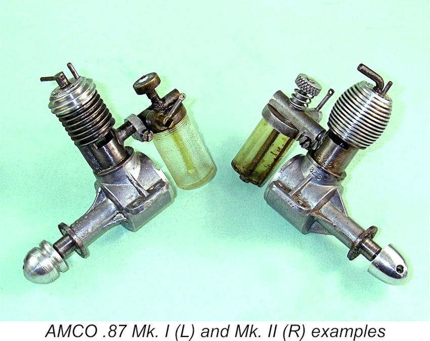
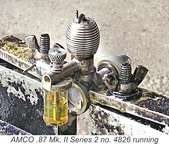
It would appear that the changes which eventually produced the AMCO .87 Mk. II model appeared progressively and that the strengthened case was the first such component to appear. At some indeterminate point in 1948, several further design revisions were put in hand. Although functionally little changed, the resulting variant differed significantly from the original model in terms of its external appearance. The fins previously cut directly into the steel cylinder were replaced by an external thread which accommodated a screw-on aluminium alloy cooling jacket. In addition, the brazed-up venturi/cut-out/tank top assembly was replaced by a die casting, with the tank being secured by a wire clip rather than being threaded into the underside of the tank top as in the case of the Mk. I variant.
The lowest reported serial number for this variant is illustrated engine no. 4432 formerly owned by the late Bert Streigler. It appears that relatively few of these models were produced before a further modification was introduced. This took the form of a completely revised cylinder which dispensed with the soldered-on external bypass used previously. Instead, the cylinder had substantially thicker walls which accommodated a pair of internally-formed bypass/transfer flutes placed side by side at the front with a land between them to prevent fouling by the now-exposed gudgeon pin. Somewhat strangely, these flutes terminated well below the exhaust ports, thus increasing the blow-down period very significantly and reducing the transfer period to around 90 degrees from the 130 degrees of the Mk. I model. This might well negate any positive benefits arising from the additional bypass area.
As a result of the initial retention of the external bypass passage, there ended up being two distinct variants of the AMCO .87 Mk. II. Although the manufacturers themselves never distinguished between these variants, it’s convenient for discussion purposes to refer to them as the Series 1 and Series 2 variants respectively.
The Mk. II Series 2 version was first advertised in December 1948 at a reduced price of £3 12s 6d (£3.63). The advertising material as reproduced at the left stated that this was virtually a new engine The advertisement also indicated that significant changes were made to the crankshaft and other moving parts. An examination of the accompanying component view of a Mk. II Series 1 engine shows that most of these changes had already been implemented some time previously but never advertised. Nevertheless, the switch from the single external bypass to an internally-formed multiple transfer arrangement which defines the Mk. II Series 2 variant was a major change which would lead us to anticipate an enhanced performance from the Series 2 model if it were not for the drastic decrease in transfer period which inexplicably accompanied this change. Serial Numbers and Production Figures
The best explanation that I can come up with is that the original soldered-bypass Mk. II model (which I’ve called the Mk. II Series 1) was the Mk. II AMCO .87 as originally designed. After perhaps five hundred examples had been produced, Ted Martin decided to try the switch to internal bypass flutes, resulting in the appearance of the Mk. II Series 2 variant as featured in the AMCO advertising from December 1948 onwards.
Looking at the serial number sequence just summarized, it appears that perhaps as many as 4,000 examples of the Mk. I version were produced. The split between Series 1 and Series 2 examples is unclear at the present time, although present indications are that the 4-web Series 2 variant predominated. These were followed by perhaps 500 examples of the Mk. II Series 1 model before the appearance of the Mk. II Series 2 variant. Presently available serial numbers suggest that only 500 or so examples of that model were produced, making this by far the rarest version of the AMCO .87 diesel. Once the Mk. II Series 1 model was restored to production status, it appears that perhaps some 2,500 further examples were produced in total. Overall, it would appear that around 7,500 examples of the AMCO .87 in all its variants were produced during the engine's production life. By the standards of competing companies like E.D., this represented a very modest rate of production, emphasizing the fact that model engine manufacture was always a sideline activity for the Anchor Motor Company. The AMCO .87 Mk. II on Test
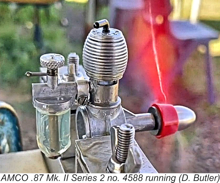
Somewhat oddly, the illustrations which accompanied Chinn’s review are mutually inconsistent. The photograph of the engine (right) clearly showed a Mk. II Series 1 model with its soldered-on external bypass, while both the text and the 3-view drawing The engine in the photograph also had its tank secured with a wire spring-clip, which seems to be indicative of a Mk. II Series 1 example. The engine in the 3-view drawing has its tank secured by a screw into the fuel pickup tube at the base, along the lines of my own previously-illustrated Mk. II Series 2 example as well as Derek Butler's previously-cited engine no. 4588. After summarizing the previously-described changes that had resulted in the appearance of the AMCO Mk. II Series 2 model as tested, Chinn reported that the engine started “very well indeed”. No port prime was reportedly required – after a couple of choked flicks, the engine started easily from cold. A warm engine could be “easily re-started with one choked flick, without touching either compression lever or needle valve”. Neither compression nor mixture controls were in the least bit critical. Chinn In terms of its running qualities, Chinn reported that the engine “behaved well at all speeds, running smoothly and holding even revolutions”. He found that the cut-out worked perfectly, in contrast to Sparey’s criticism of the comparable fitting on the Mk. I version. The one fly in the ointment from Chinn’s perspective was the fact that the performance of his test Mk. II example “did not appreciably differ from that of a Mk. I version tested earlier”. That said, he did measure a peak output of 0.047 BHP @ 8,400 RPM, which he noted was very close to the manufacturer’s performance claim for this model. Chinn noted that the AMCO was best suited for free flight applications, both power-duration and scale or semi-scale types. He summed up the engine as “a thoroughly practical engine for general purpose or competition flying, as many contest successes show, and is also strongly recommended to the beginner acquiring his first engine”. A fine video of Derek Butler’s Mk. II Series 2 engine no. 4588 running may be found here. Derek's engine managed 8,500 RPM on a Kaysun 7x5 airscrew. A Latter-day Comparative Test
First up was Mk. I Series 1 engine no. 86 – a very early example. This unit has clearly seen a fair bit of previous use, consequently appearing to be well freed-up. Based upon past experience with this particular engine, I anticipated no difficulties. Nor was I disappointed ……… The engine proved to be an extremely easy starter, although like Maris I found that a small exhaust prime was a great aid to a quick start. Following the administration of such a prime, the engine invariably started within a few flicks. The engine would start on choking alone, but it was easy to flood the case using this approach. It took a bit more flicking along with some fiddling with the comp screw to get the engine going under these circumstances.
The one issue that did present itself was the fact that while the cut-out worked well enough, its action was a little delayed. After triggering the device, the engine instantly slowed dramatically. However, it took a few seconds for the engine to become starved of fuel mixture and stop completely. It would appear that the fit of the cut-out plunger on my test example was a bit on the slack side, allowing some leakage of mixture even when triggered. That said, the engine invariably did stop – it just took a few seconds to do so.
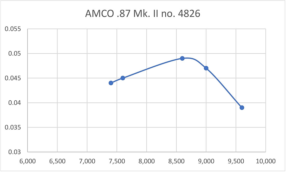
It didn’t take long to realize that there must be a massive air leak somewhere. This diagnosis proved to be quite correct! The crankcase was very well sealed, as demonstrated by a solvent immersion test. So that wasn't the cause. The culprit turned out to be the slot behind the split-clamp section of the carburettor casting Once that issue was sorted, the engine gave no further trouble. It more or less duplicated the starting and running characteristics of its Mk. I Series 1 predecessor in the test stand, the one difference being that it did not require a port prime for prompt starting. This must be due to the different transfer arrangements. A single choked flick invariably produced a very prompt start, hot or cold. The Mk. II unit appeared to have had a little less previous use than the Mk. I example, but still performed very smoothly and consistently throughout, with very prompt starting on all props provided that a small prime was administered. The cut-out on this example worked perfectly. Using the same props and fuel in both engines, the following data were obtained:
The above data make it clear that the two test engines performed at very similar levels, with the Mk. II having a very slight edge. The Mk. I unit appears to have developed around 0.045 BHP @ 8,600 RPM, while the Mk. II engine managed around 0.049 BHP @8,600 RPM. A few general comments appear to be in order. First, both of my test engines seemingly performed at a somewhat lower level than Maris’s Mk. I Series 2 engine no. 2170. Having noted this point, it’s interesting to observe that Mk. I engine no. 86 duplicated Sparey’s curve for the same model almost precisely. Likewise, Mk. II engine no. 4826 produced an almost exact duplicate of Chinn’s results for that model. It would appear that Maris’s Mk. I unit is a quite exceptional example! This further reinforces the evidence for considerable performance variations between different examples of this engine. I subsequently put a few runs on my Mk. I Series 2 example no. 3204. It handled in an identical manner to its Series 1 predecessor in the test stand, also turning the same props at speeds within 100 RPM or less of its Mk. I Series 1 companion no. 86. To all intents and purposes, the starting and running characteristics of the two engines are as close to identical as you can get! Advertising History
As noted previously, the first Anchor Motors advertisement for the .87 Mk. I appeared in the August 1947 issue of “Aeromodeller”. This issue of the magazine actually appeared on the news-stands in mid-July. It would appear that at that point in time the engine was still in its pre-release stock build-up stage, since the ad specifically stated that the engine "...will be available shortly at your model shop..." Evidently distribution had not yet commenced. The manufacturer advertisements continued through the rest of 1947, although the fact that the placements for October and November 1947 were still saying “Watch the window of your model shop for it!” implies that distribution was still far from comprehensive. It was December 1947 before the AMCO .87 first began to appear in published model shop listings. This coincided with the placement by the Anchor Motor Co. of a full-page colour advertisement as reproduced at the right. It appears that it was only at this point that the engine became generally available – just in time for Christmas! The advertised selling price was £4 4s (£4.20). From this point onwards, the engine made regular appearances in model shop listings. The manufacturers also continued to place regular advertisements of their own. These advertisements displayed minor changes in format from one month to the next. Oddly enough, the Mk. II Series 1 variant of the engine appears never to have been specifically promoted – the illustrations in the company advertisements continued to depict the Mk. I version right through to November 1948. It was only in December 1948 that the Mk. II model was introduced through the placement of the full-page advertisement which was reproduced earlier, this time in the name of Anchor Motors. Moreover, that introductory advertisement referred unambiguously to the Mk. II Series 2 variant with its various internal modifications which were described earlier. The advertised selling price was £3 12s 6d (£3.63). The existence of an earlier Mk. II variant which retained the soldered-on external bypass is beyond dispute – the serial number record proves that. It appears that the manufacturers themselves chose not to advertise any changes to the original design until all of the planned changes had been introduced. This process seems to have been progressive, spread out over a period of time, beginning with the strengthened case and proceeding through the revised fuel system, screw-on cooling jacket and full-disc crankweb to the modified cylinder porting.
Anchor Motors Ltd. continued to run their regular ads for the AMCO .87 Mk. II Series 2 through to April 1949. However, that advertisement (reproduced at the left) proved to be their final advertisement for the engine - in May 1949 the focus of their advertising switched decisively to their newly-introduced AMCO 3.5 PB model. There was no further reference to the old .87 model, while appearances of the engine in dealer listings steadily declined, the last being in October 1949. The above summary gives the impression that production of the fully-developed AMCO .87 Mk. II Series 2 was confined to the period November 1948 – April 1949. This would explain the fact that this model is considerably less commonly encountered than the Mk. I variant.
Raylite had clearly gained access to a sufficient supply of these engines to make such an advertisement worthwhile. Even so, the ad stated that “only a limited amount will be made available”. The cited price was unchanged at £3 12s 6d (£3.63). It's impossible to say for sure whether or not this implied a resumption of limited production at some level by Anchor Motors. Their own advertisements continued to focus on the 3.5 cc models, with no mention of the AMCO .87. While this might be taken to prove that Raylite had somehow gained access to a sizeable inventory of existing New Old Stock, the fact remains that the AMCO .87 made periodic re-appearances from this time onwards in various dealer listings all the way up to May 1952, when Anchor Motors formally announced that they were divesting themselves of their model engine range. Hence the possibility that some level of production had resumed cannot be ruled out - it's hard to explain the resumption of dealer advertising in any other way. If this was how it went, the examples produced at this stage may have been the Mk. II Series 1 models having higher serial numbers than the reported Mk. II Series 2 examples. Perhaps the tooling for that model had been lost or damaged, prompting a return to the earlier variant. Regardless, the fact that Peter Chinn A further degree of support for this possibility is to be found in the fact that the Anchor Motors advert in the September 1951 issue of “Model Aircraft” (reproduced at the left) included the AMCO .87 along with the AMCO 3.5 PB glow-plug model and the AMCO 3.5 BB diesel as being part of the company’s then-current range. The price of the AMCO .87 was still quoted at £3 12s 6d (£3.63) including prop. It’s difficult to see any justification for such an inclusion if the engine was not still being made available at some level by the company. It’s interesting to note that the manufacture of the 3.5 PB diesel had evidently been discontinued at this point, since it was not included. After May 1952, only Raeburn and Roland Scott continued to list the .87 in their “Aeromodeller” advertisements through to November 1952. These were the engine’s final advertising appearances. No doubt the odd unadvertised example continued to be available over the counter in various shops for some time after this. The Aftermath
In late 1951, following his successful development of the AMCO 3.5 BB, Ted Martin accepted a position with General Motors Canada as an automotive engineer, ending his 4-year association with the AMCO range. Ted's move to Canada was fortuitous as events were to prove, because the involvement of the Anchor Motor Co. with model engines was coming to an end in any case. Following the outbreak of the Korean War in June 1950, the company had received a major contract from the Ministry of Defence to develop and manufacture a military version of the 500 cc twin-cylinder Triumph motorcycle engine for the purpose of powering field generators, pumps and the like.
Consequently, the AMCO trade-name (which by then had considerable brand recognition value), designs, components and dies were offered for sale. They were eventually purchased by a newly-formed London-based company, the Aeronautical Electronic & Engineering Co. of Alperton, Middlesex (near Ealing), who carried the AMCO name on for a few more years. But that's another story which has been related elsewhere. Suffice it here to say that the AMCO .87 was never re-introduced by the new owners. The Anchor Motor Co. remained in business for many years following the end of their involvement with model engines, finally closing their doors in 1983. Today the location at which they produced the AMCO engines has been extensively redeveloped, much of it being absorbed by the Grosvenor Shopping Centre, although The Newgate still exists. The fate of the machine shop facilities on Victoria Road is unknown. __________________________ Article © Adrian C. Duncan, Coquitlam, British Columbia, Canada First published on MEN September 2007 This revised edition published here November 2024 |
|||||
 In this article, I’ll review one of the most respected model diesels to originate in early post-WW2 Britain. I’ll be looking at the AMCO .87 side-port diesel of 1947 - 1951. This little engine was deservedly held in high regard by contemporary aeromodellers and remains a sought-after collector’s item today.
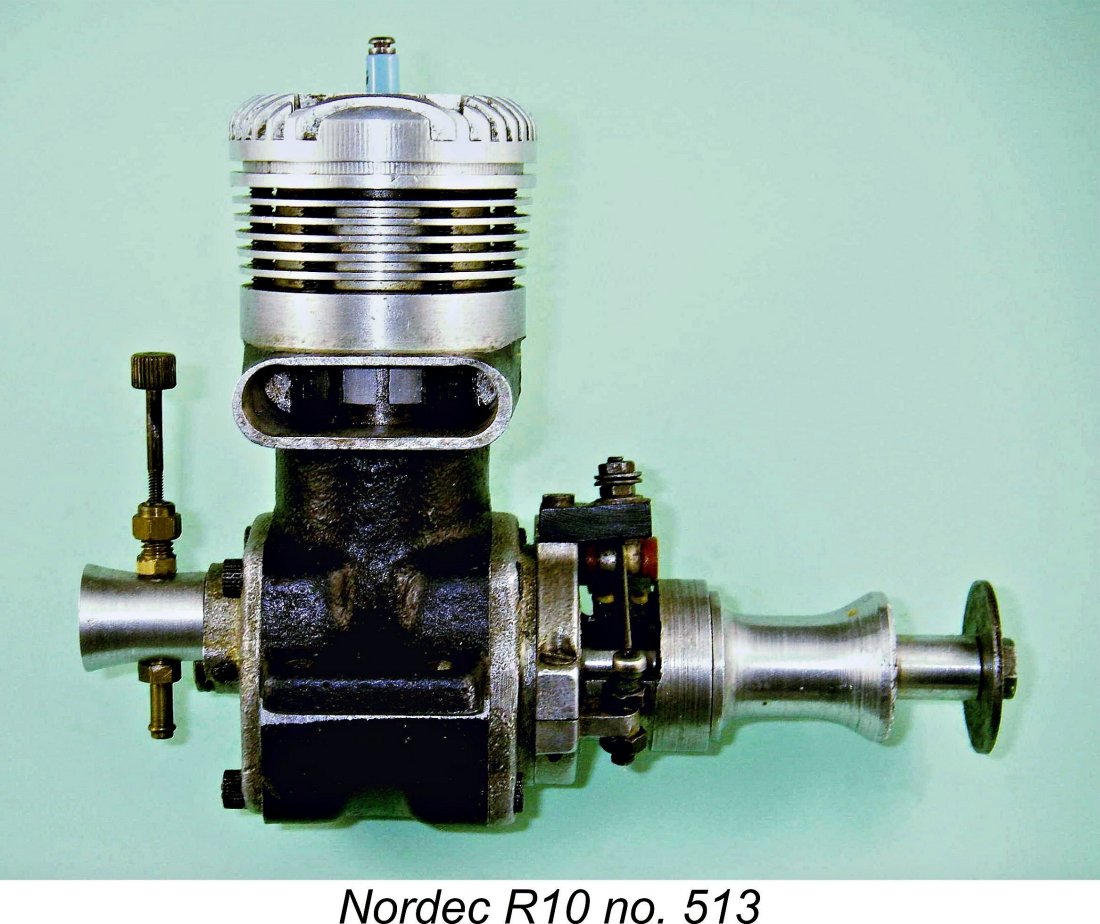
 diesels, etc.). They also made custom vehicles for specialized transportation applications in the agricultural and other fields. The machine shop thus lay at the core of the company's business.
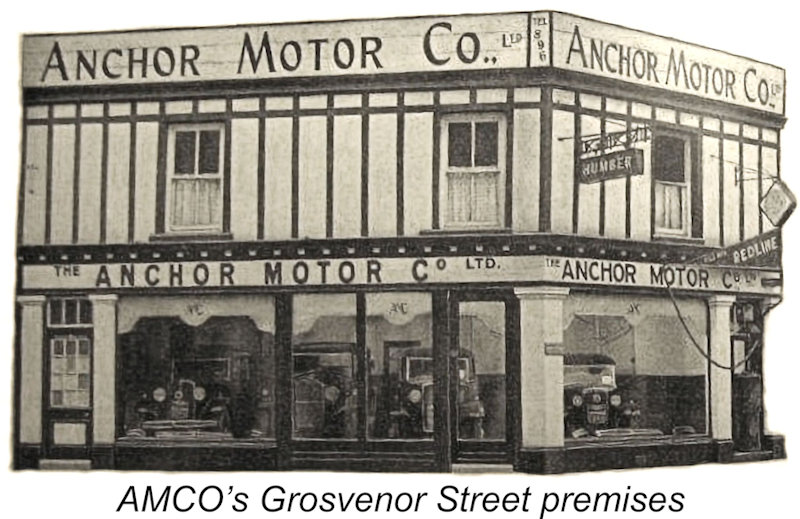
 The importance and required high standards of this war-related work allowed the company to keep its machine tool inventory well up to spec, replacing worn equipment as necessary. As a result, the company entered the post-war period with a machine tool inventory that was of excellent quality and in fine condition, a luxury enjoyed by few other early post-war British model engine manufacturers.
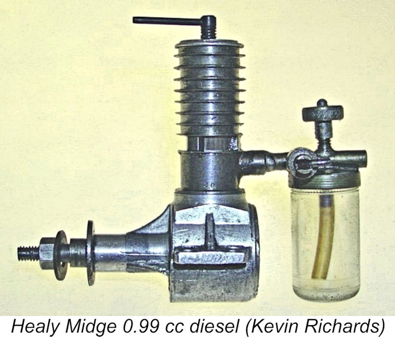 At about the same time, a certain Basil Healy of Ilford in Essex was developing his own design for a small model diesel engine called the Midge and manufacturing it in very small numbers in his home workshop for sale locally. The stereotypical one-man "garden shed" operation, in fact! The Healy Midge was made in several displacements from 0.5 cc through 0.99 cc to 1.2 cc. Healy's location has often been reported as Rayleigh, Essex, but the late
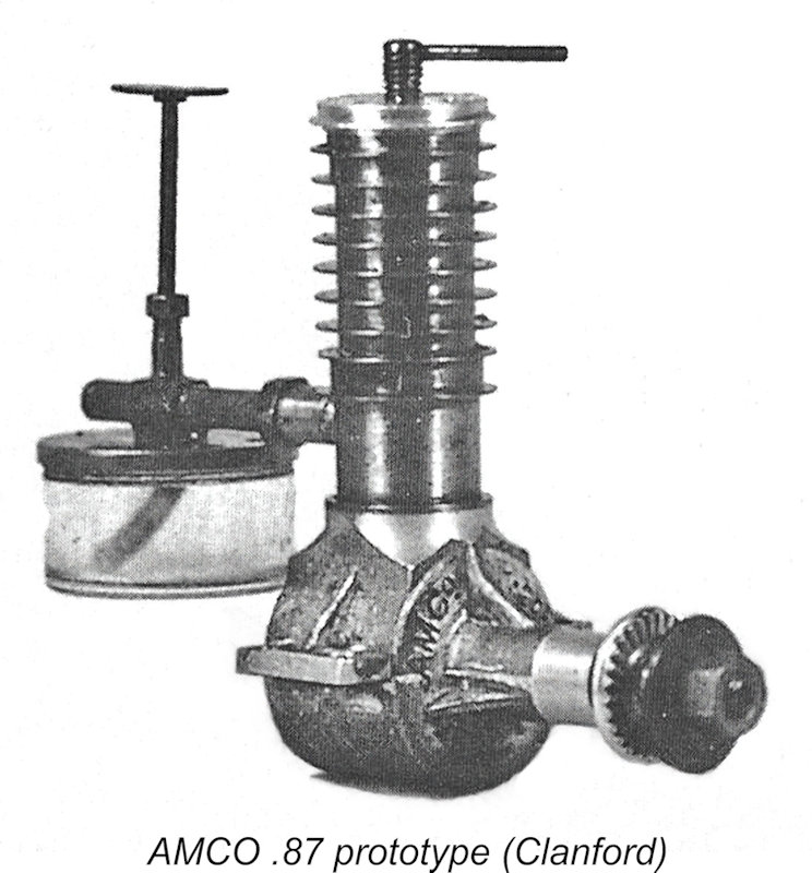
 The AMCO .87 Mk. I was a typical long-stroke side-port diesel of its era. With a bore and stroke of 0.375 in. and 0.472 in. respectively (9.524 mm and 11.989 mm), it featured a healthy stroke/bore ratio of 1.26 to 1. Its true displacement was 0.854 cc (0.053 cuin.), a little under the nominal 0.87 cc figure. Checked weight was 2 ounces (56 gm) exactly complete with tank.
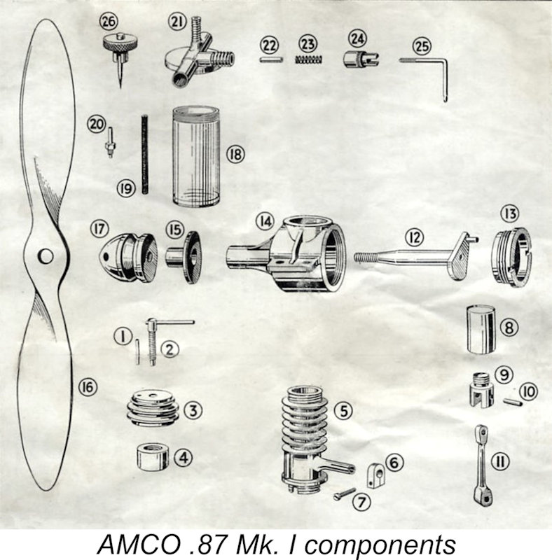
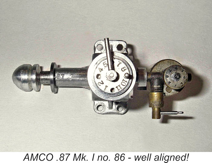 Ted recalled that this approach allowed for only two re-assemblies at most before mis-alignment of the induction tube became an issue as the cylinder seat wore down. After this, re-shimming was required. This is why so many AMCO .87's today show the infamous "5 past 12” carburettor alignment! If you have a well-aligned example, leave well alone!!
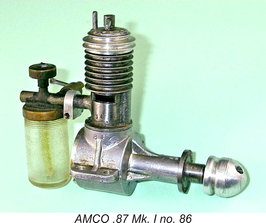 Moving on downwards, the engine featured a hardened steel conrod. This was a common feature in model diesels of the late 1940’s – the various
  At the rear, the delivery end of the induction boss was externally threaded 2BA for a short distance, engaging with a matching thread in the cylinder wall prior to soldering. Given the minimal thickness of the cylinder wall, it’s clear that the intent of this thread was merely to hold the boss in the correct alignment during soldering. Primary reliance was obviously placed upon the solder, although the thread doubtless enhanced the structural integrity of the assembly. The finishing of the bore must have been left until after the soldering was complete.
 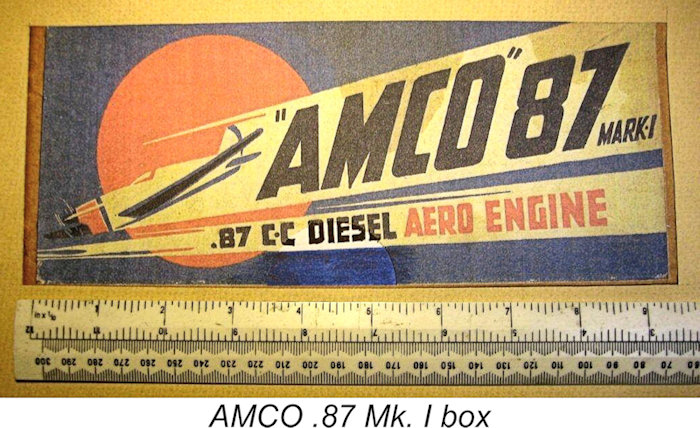 Each engine was supplied in a colorfully-labeled box with a highly detailed instruction leaflet, a matching airscrew (which forced the use of a very long box!) and a special combination tool. My illustrated example still has that tool with it, although the leaflet, airscrew and box are long gone.
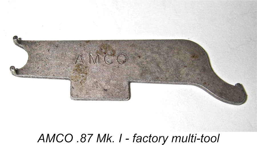
 The
The 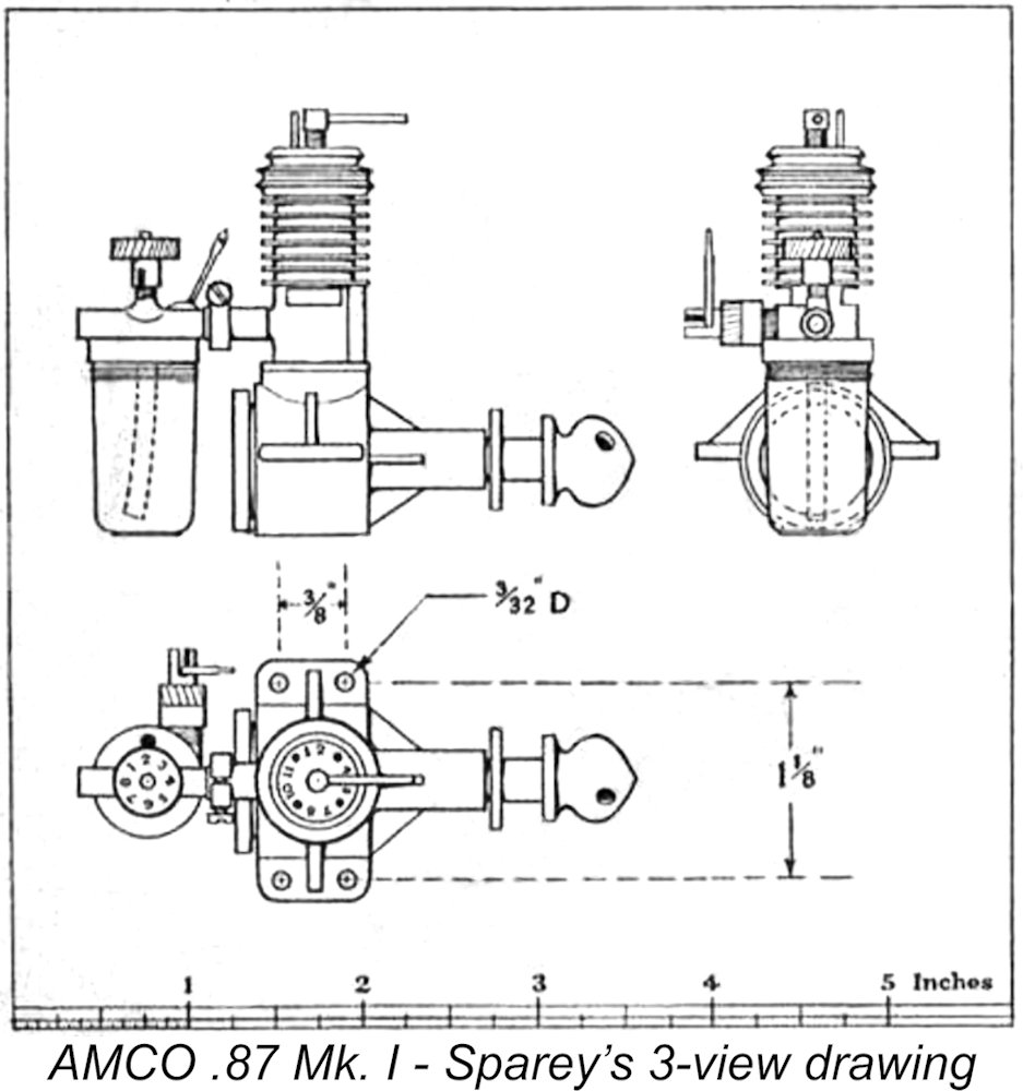 The AMCO .87 Mk. I was among the first engines to be tested by
 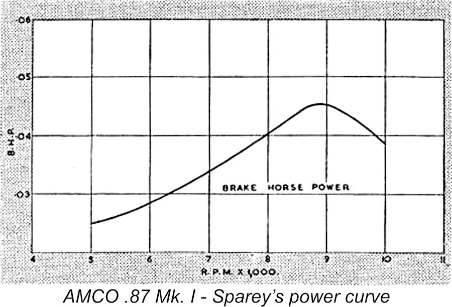 An interesting note regarding Sparey’s test report is the fact that the stroke was given incorrectly! Sparey reported the bore and displacement accurately, but gave a stroke measurement of 0.412 in. (10.46 mm) instead of the correct measurement of 0.472 in. (11.99 mm). Direct measurement of my examples has proved Sparey’s figure to be wrong. This was almost certainly an uncaught type-setting error - the correct "7" was inadvertently replaced by a "1".
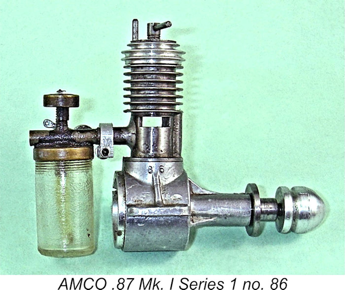
 As a result of Ted’s deliberations, the AMCO .87 Mk. I did not remain in production all that long as originally released. It would appear that some trouble was experienced with the main bearing housing, which was stiffened with only three quite modest webs, as seen in the earlier images of the AMCO .87 Mk. I. At some point during the production run, a revised case was adopted which featured four somewhat more substantial stiffening webs. This must surely be Ted Martin’s response to a perceived weakness in the original design. The revised case evidently solved the problem, because it was to be retained throughout the remaining production life of the AMCO .87, including the Mk. II model (see below).
 The development of the Mk. II AMCO .87 was doubtless spurred on by the August 1948 appearance of the
 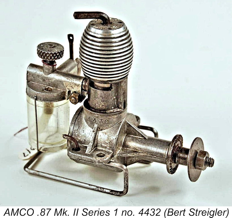 The bypass/transfer arrangements remained unchanged at this stage – the soldered-on external bypass passage continued to be used. The matched serial numbers on the case and cylinder were retained, since the need to keep both together as a pair still existed.
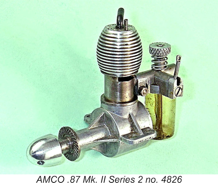 In addition, the tank was now secured through the use of a hollow brass tube extending to the bottom of the tank, which was retained by a machine screw which threaded through its base into the tapped bottom of the hollow tube. Two small opposing holes were drilled though the wall of the tube at the bottom to provide fuel access from the tank.
 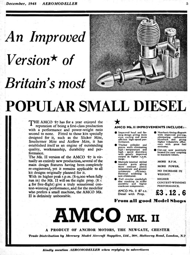 The major feature that distinguishes the Mk. II Series 1 from its Series 2 successor is the retention of the soldered-on external bypass on the original Mk. II Series 1 models. The Mk. II Series 1 version with the screw-on cooling jacket and external bypass never appeared in an AMCO advertisement, although the reality of its existence is attested irrefutably by the existence of a number of confirmed examples.
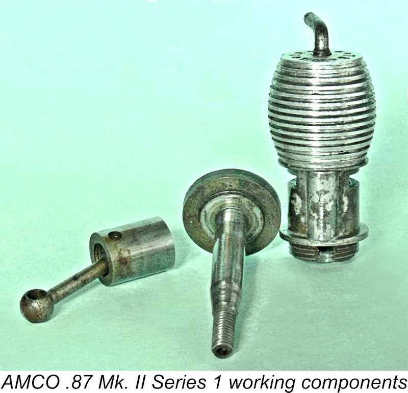
 A major problem that we face here is that the numbering sequences for the Mk. II Series 1 and Series 2 are remarkably muddled! Since engine no. 3873 is a confirmed Mk. I Series 2 example and we are aware of previously-illustrated Mk. II Series 1 engine no. 4432, the Mk. II Series 1 model must have appeared at some point between those two numbers. However, by the time we arrive at serial number 4588 owned by Derek Butler, we encounter the Mk. II Series 2 variant as seen at the left. The only other personally-confirmed serial numbers that I have for the Mk. II Series 2 variant are my own previously-illustrated engine no. 4826 and engine no. 5080 which passed through Kevin Richards’ hands some years ago.
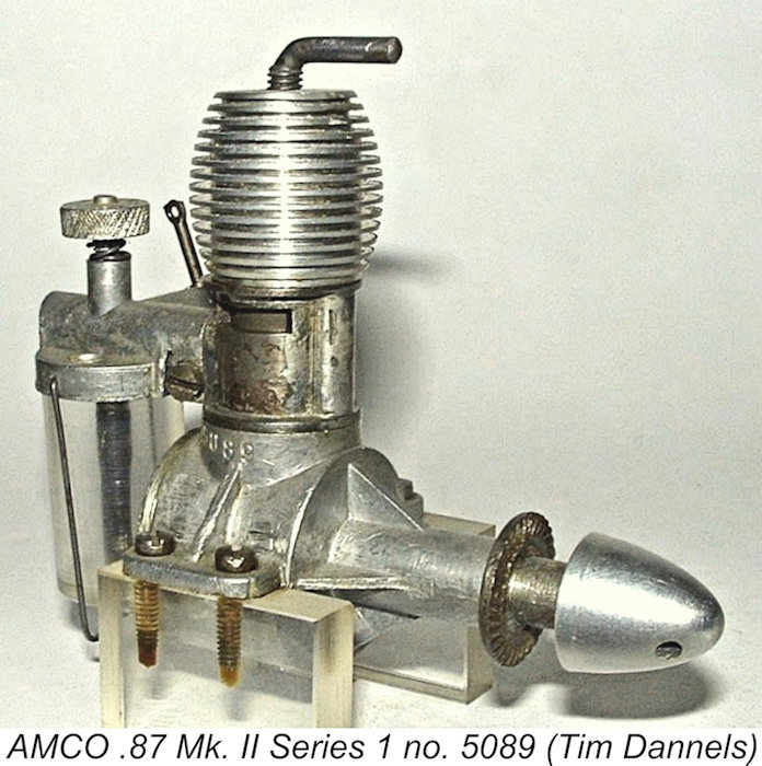 To further confuse the issue, engine no. 5089 formerly owned by Kevin Richards reverts to the Mk. II Series 1 type!! In fact, all other reported serial numbers above this are associated with Mk. II Series 1 models with the soldered-on bypass, all the way up to engine no. 7403. Go figure…………
 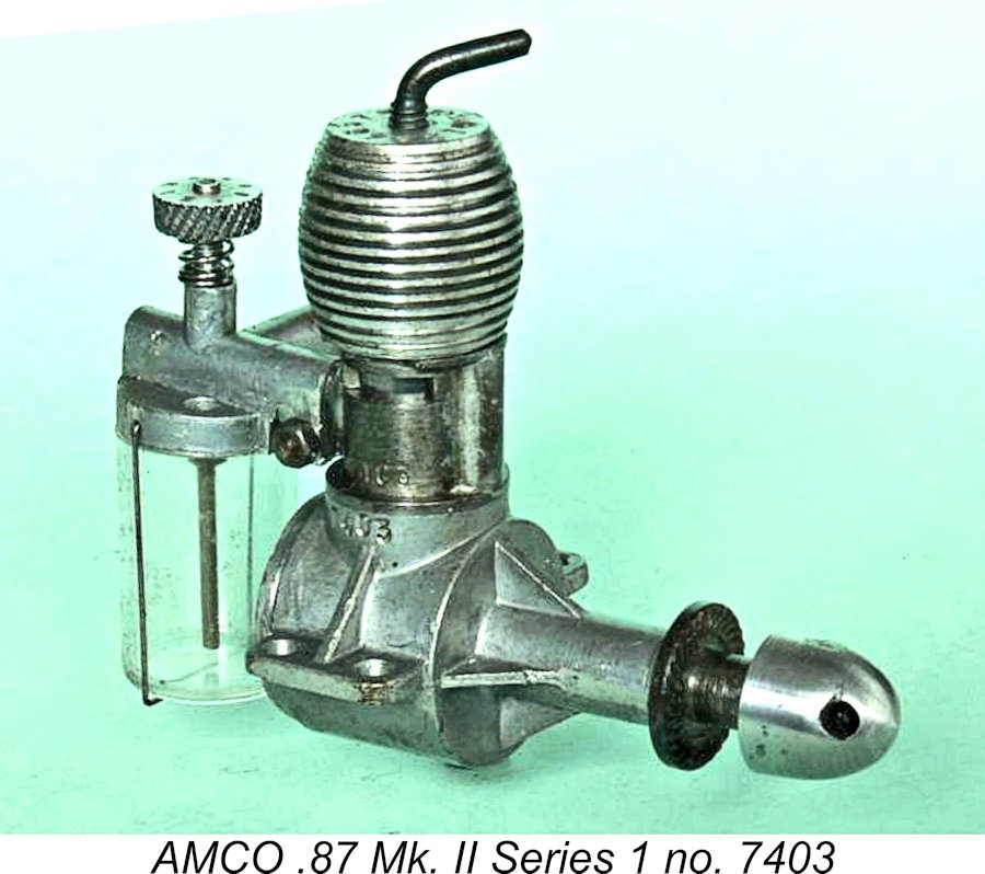 However, as we shall soon see, the revised bypass arrangements did not produce any significant performance improvement. Consequently, the revised design was evidently judged to be a failure, resulting in the manufacturer reverting quite quickly to the Mk. II Series 1 variant for all subsequent production.
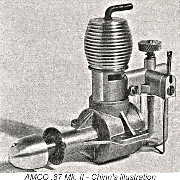 The revised design described above was the subject of a
 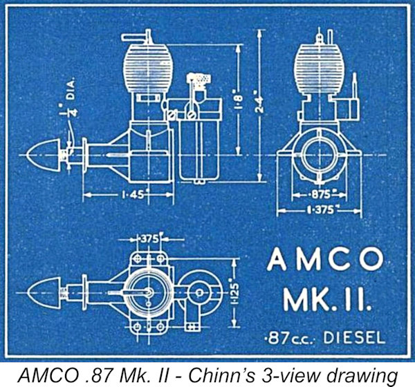 (left) reflected the Mk. II Series 2 variant.
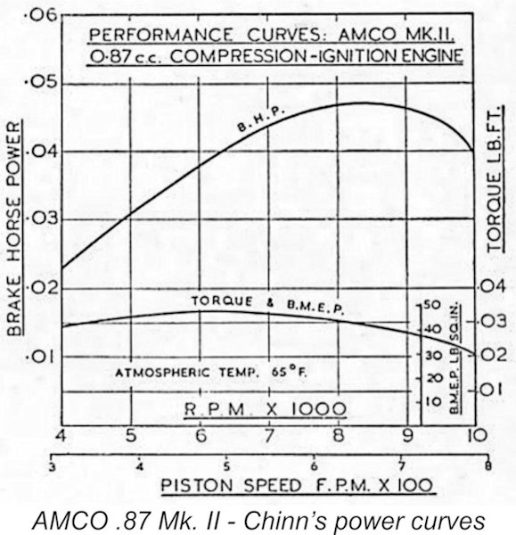
 It will have become apparent from the foregoing that the available evidence seems to prove quite conclusively that the performance of the AMCO .87 varied widely between different examples of the same model. Nonetheless, since I had nice examples of both Mk. I and Mk. II models on hand, it seemed worthwhile putting them both into the test stand at the same session using the same props and fuel, just to get a feel for their relative operating characteristics. I used an equal-parts blend of ether, kerosene and S.A.E. 60 mineral oil, to which I added 1% improver.
 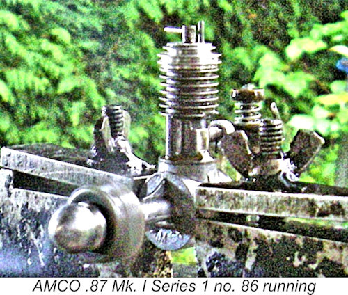 The test engine was formerly owned by my late Canadian friend Sqn. Ldr. Laurie Ellis of "Vultan" and “Javelan” fame, who had owned it from new and had clearly put it to good use. Once running, it was completely free of the inconsistencies and tendency to sag that had afflicted Maris’s example, running smoothly and consistently on all props tested. I found it a genuine pleasure to operate.
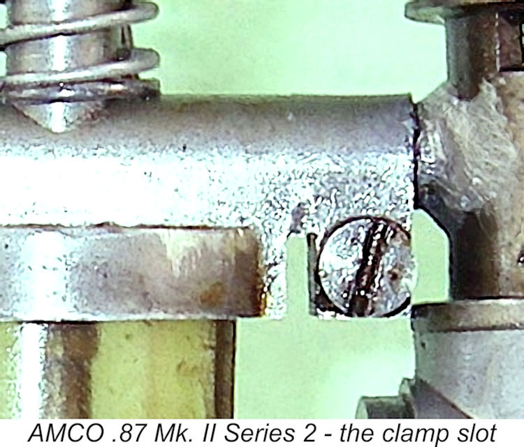
 At my request, my valued Aussie friend and colleague Gordon Beeby kindly undertook one of his extremely comprehensive reviews of the advertising history of the AMCO .87. This review proved to be surprisingly informative – well worth sharing here. My very sincere thanks to Gordon!
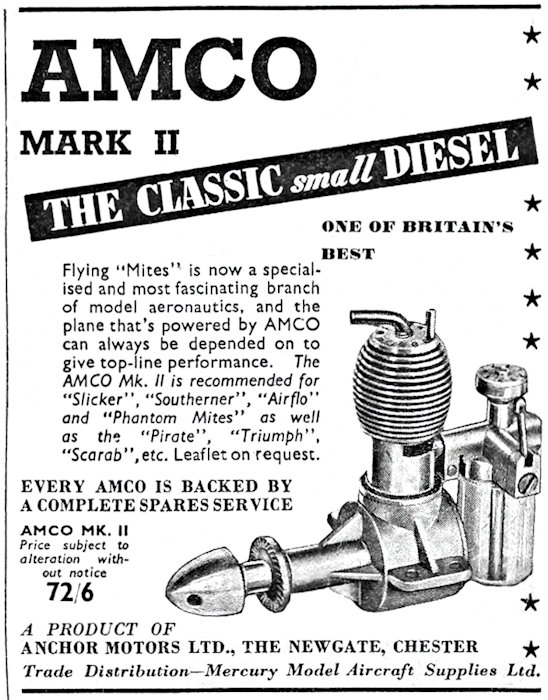
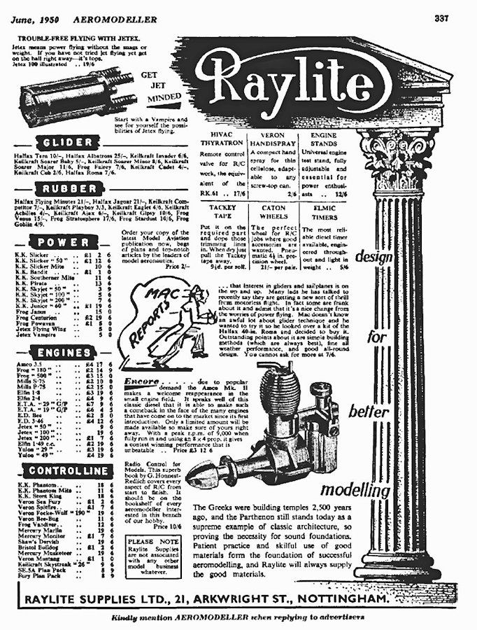 That leaves us having to explain the re-appearance of the engine in mid-1950. In the June 1950 issue of “Aeromodeller”, the prominent Nottingham model dealer Raylite placed a full-page advertisement which (among other things) announced an “encore appearance of the AMCO .87 Mk. II”, as seen at the right. This wording suggests that there had indeed been a hiatus in production for some time previously. The late 1949 cessation of advertising from other dealers supports this view quite strongly.
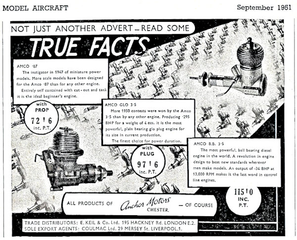
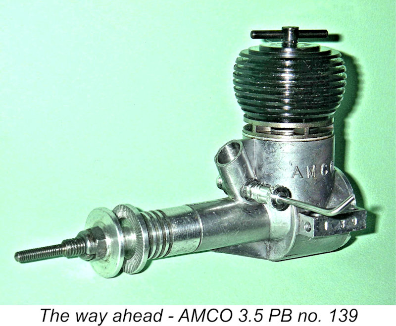 We must now return briefly to May 1949 to take up the story of the AMCO venture from that point onwards. The success of the AMCO .87 was such that by 1949 the AMCO name stood high in the affections of British and Commonwealth modellers. This set the stage for a favorable response to the company’s first venture into a larger displacement category, which came in May 1949 with the announcement of the soon-to-be-famous
 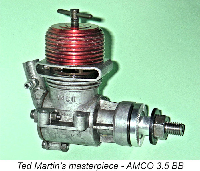 Once they reached the manufacturing stage of this project, the Anchor Motor Co. found themselves with insufficient resources to maintain production of the very popular 3.5 cc engines (PB and BB) at levels which matched demand. We saw earlier that the 3.5 PB model had already been discontinued as of September 1951. The other models soon followed.
| |