
|
|
The Mamiya 29 models
I’ve also published separate articles dealing with the series of engines in the .099 and .15 cuin. displacement categories which were marketed under the Mamiya trade-name. Time now to move on to look at the various Mamiya .29 cuin. models. A final article dealing with the .60 cuin. Mamiya models will appear here in due course. We saw in my overview article that as of 1948, the manufacturers of the Mamiya model engine range, Tokyo Hobbycrafts, had made a noteworthy entry into the highly competitive field in which they were a participant with their release of a fine .60 cuin. spark ignition model. They were now poised to expand into the “popular” displacement categories for which mass sales might reasonably be expected.
Although the larger "Chochin" model's displacement fell a little shy of the full .29 cuin. figure, it clearly belongs in the series of Mamiya engines in that displacement category. Accordingly, I’ve elected to include it here. This quite rare engine was replaced in 1949 by the completely revised loop scavenged .29 cuin. FRV model illustrated earlier. This is the version of the Mamiya .29 which is most familiar to engine collectors. It was only during the research phase of this study that I became aware that there were at least three distinct variants of this design. I’ll describe these in the order in which current information from Japan allied with design considerations suggests that they appeared. I’ll also look at the three known variants of the companion Mamiya 29 rear rotary valve (RRV) model. Before doing so, it’s necessary to note the fact that there’s presently no direct evidence to suggest that any Mamiya .29 model was ever offered by the manufacturers in spark-ignition form. My reasons for making this statement were summarized in the overview article relating to this range. The few spark-ignition examples which do undoubtedly exist appear to be the work of enthusiastic collectors rather than Tokyo Hobbycrafts, the makers of the Mamiya engines. With that out of the way, it’s time to take a close look at this interesting series of model powerplants! But before getting started, I’d like to acknowledge the assistance rendered by Alan Strutt of England. Alan was most generous in providing access to examples for study as well as reviewing and criticising the text as it developed, constructively challenging my conclusions every step of the way. While I accept full responsibility for the comments and conclusions set out below, I wish to make it clear that any merit which this study may possess owes much to Alan’s input. A Predecessor - the Mamiya “Chochin” .275 cuin. Model
The simultaneous introduction of the Mamiya “Chochin” models in both .097 and .275 cuin. displacements appears to represent an entirely logical move towards the production of engines having broader “consumer” appeal than the rather specialized .60 cuin. spark ignition model which preceded them. Both models were presumably designed by the principal owner/operator of Tokyo Hobbycrafts, Minoru Sato. To all external appearances, the .099 and .275 cuin. “Chochin” models were more or less identical in design terms. Both featured screw-in construction allied to a radially-ported blind-bored cast-iron cylinder having integral cooling fins. No screws were used in their assembly.
It should be understood that the “Chochin” name applied to these engines was a colloquial Japanese modeller’s nickname as opposed to a factory designation. The term was based on the general resemblance of the finned cylinders of these models to the traditional Japanese “Chochin” bamboo-and-paper lantern.
The transfer port of the smaller model consisted of a continuous annular groove around the entire inner circumference of the cylinder wall immediately below the exhaust ports – a genuine 360º transfer port! This channel was supplied with mixture through a series of shallow bypass flutes formed in the cylinder wall below the annular channel which served as the actual transfer port. A similar arrangement was featured in the Japanese Fuji 29 models as well as in several products of the British “K” Engineering Co. It seems reasonable to suppose that a similar arrangement may have been featured in the larger .275 cuin. model, but at present I have no direct evidence for this. In the absence of an actual example to study, I’m unable to say more about the “Chochin” .275 model at this time. I would be most openly grateful to any reader who can throw more light upon this very rare engine for us! The Mamiya 29 FRV Glow-Plug Model - First Variant In the latter part of 1949, the Mamiya manufacturers updated a number of their established designs. The .60 cuin. FRV spark-ignition model appears to have been replaced by a rear disc valve glow-plug model at about this time. Much more of the Mamiya .60 models elsewhere. In addition, the two “Chochin” models were both supplanted by completely different and far more up-to-date designs of generally similar displacements.
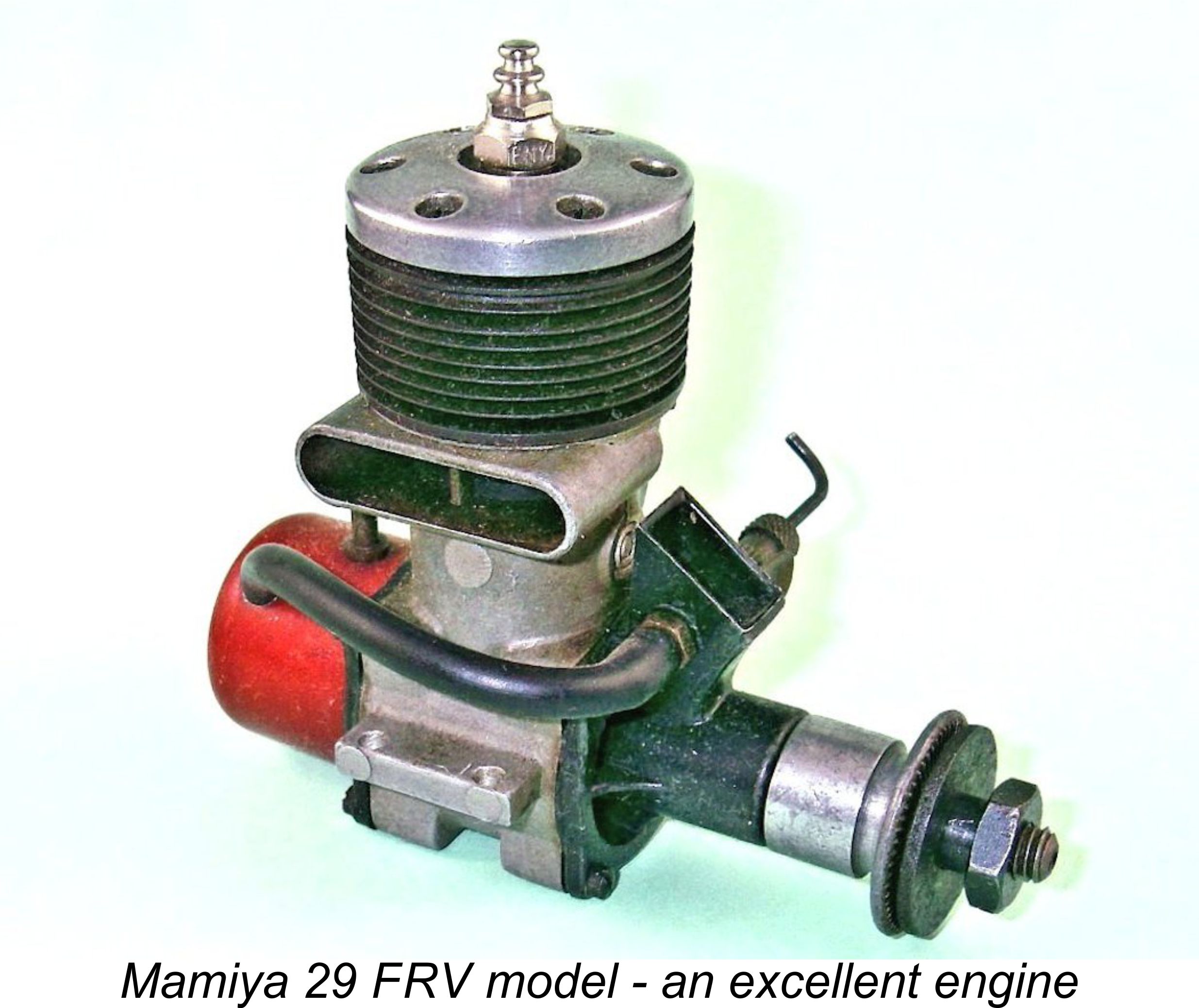
A number of those features suggest a degree of design influence from the American Ohlsson & Rice (O&R) engines. There can be little doubt that substantial numbers of the O&R motors must have appeared in Japan in the hands of US servicemen as a result of the post-WW2 occupation which began in late August 1945, and the Mamiya designer clearly had ample opportunity to study these and other US designs of the period. The Mamiya 29 established a definite Mamiya “house style” which was to be carried through the early 1950’s with their succeeding FRV glow-plug models in both .29 cuin. and .099 cuin. displacements. It featured conventional cross-flow loop scavenging with a chemically-blackened steel cylinder having integral cooling fins, a baffle piston and a separate bolt-on alloy cylinder head. Pressure die-casting was used throughout for all the cast components. As supplied, the exhaust stack of the .29 cuin. model was located on the right-hand side (looking forward), although these engines could be re-assembled with the stack in the opposite configuration by switching end covers. Bore and stroke were 19.0 mm and 17.0 mm respectively for a displacement of 4.82 cc (.294 cu. in.). The engine weighed in at 6½ ounces (186 gm) all inclusive with tank. None of these models appear to have carried serial numbers.
In combination with a similarly-shaped register port in the bearing surface, a rectangular crankshaft induction port gives extremely rapid opening and closing of the induction tract allied to a large induction area at the interface. However, full advantage was not taken of this possibility in the Mamiya, since the register port in the bronze bushing which supported the actual shaft journal was round, presumably as a production simplification. The rectangular crankshaft port still gave more rapid opening and closing than a round hole would have done, but the effect was somewhat attenuated by the circular register port. To offset this, the diameter of the register port was a relatively generous 6.5 mm, matching that of the internal gas passage in the centre of the shaft. This resulted in an induction period which was quite lengthy and timed aggressively by normal plain-bearing “sports engine” standards - a full 180 degrees (40 deg. ABDC to 40 degrees ATDC) in the case of the two examples which I have measured directly. Overall, one would expect the Mamiya’s design to result in a relatively free-breathing induction system.
The main central casting had an attractive vapour-blast matte finish. The Mamiya 29 identification was cast in relief onto the bypass, but the engines themselves carried no mention of Tokyo Hobbycrafts, nor were any further Mamiya models to do so. The front of the bolt-on main bearing housing was deeply recessed between the intake boss and the stiffening gussets, exactly as in the O&R engines. The backplate was also a bolt-on unit. Both the front housing and the backplate were painted black and secured by four machine screws. In addition, a back tank was provided, as it had been in the earlier .60 cuin. FRV model. This tank was of aluminium alloy and was anodized red, once more establishing a pattern for several future models. The sealing system used on the front and rear covers deserves some discussion at this point. In both cases, a good seal was obtained through the use of impregnated paper gaskets of plain circular form, without “ears” for the retaining screws. The retaining lugs through which the screws passed were thus entirely unsupported. This was a typical Japanese approach at the time, which works well enough as long as the gaskets are fairly thin and the degree to which the lugs can bend is limited. In the case of the Mamiya, however, this was not so. The space between the bearing housing and the rear cover was of course set by the distance between the front and rear sealing surfaces of the main crankcase casting. In the case of the Mamiya, this was insufficient to prevent the crankpin and rod from bearing directly against the backplate, and the result would be both increased friction and accelerated internal wear as the resulting metal shavings went through the working parts.
This would have been OK in itself had it not been for the fact that the gaskets were simple rings without supporting “ears” of their own. This left the hold-down lugs cast onto the front housing and backplate completely un-supported and free to bend to the breaking point if tightened down sufficiently. To compound matters, these lugs were relatively thin and lacking in structural strength.
The steel cylinder was held in place by two spot welds fore and aft below the exhaust stack level, exactly like the system used previously in the O&R engines. This approach had two marked advantages - firstly, it allowed for very neat and lightweight construction, and secondly it eliminated any hold-down stresses and potential distortion in the very thin cylinder walls. However, the disadvantage of this system was that if it became necessary to replace the piston/cylinder combination, one had to purchase a new crankcase as well. Perhaps more problematically, if the case was damaged in a manner that required its replacement, one had to pay for a new piston/cylinder set in addition. We now come to an important distinction between the first and second variants of this model. On the earlier variant, the retention of the cylinder was not entrusted solely to the two welds mentioned above. In addition to those welds, a pair of small screws passed vertically upwards through the upper crankcase flange and threaded into tapped holes in the lower cylinder flange. These screws were located off the centre line of the engine towards the transfer side, a location dictated by the presence of the exhaust stack.
The variant just described also featured a steel cylinder having integrally-machined cooling fins which were unusually thin and hence rather prone to damage in service. As noted elsewhere, the early version of the companion .099 model used similar ultra-thin cooling fins. The cast-iron piston was provided with the usual upstanding baffle generally seen in cross-flow loop-scavenged engines of this layout. However, the baffle in this instance had an arc planform rather than the more usual straight configuration. The baffle was formed on the otherwise-flat piston crown by turning with the piston chucked eccentrically rather than being cross-milled in the more usual manner. Being curved rather than straight, it remained closer to the cylinder wall at the centre than it otherwise would. This was presumably intended to improve both the velocity and directional focus of the incoming gas flow, thus improving scavenging. The underside of the cylinder head featured a curved baffle slot to match. The same approach was taken with the original loop-scavenged .099 models described separately as well as in the contemporary Haru designs.
The plain aluminium alloy cylinder head was machined from a casting and was externally polished, apparently by brushing. It was retained in place by six screws which engaged with a ring of tapped holes in the thick upper flange of the cylinder. Experience with their .60 model running on glow-plug ignition with a four-screw head may have convinced the makers of the need for this number of screws! These fasteners played no part in retaining the cylinder itself in place. On this variant, the underside of the cylinder head was diametrically relieved for some distance above the sealing face, creating a significant area of additional cooling surface below the head.
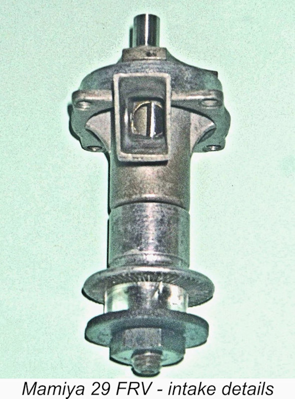
Since the area of the rectangular venturi at the spraybar location was relatively large, the engine would certainly have had extremely poor suction if run with the intake wide open. To get the best out of this engine running on suction in a sport-flying context, the use of a venturi restrictor is clearly indicated. Indeed, the manufacturers expressed their agreement with this assessment by providing just such a feature. The Mamiya .29 introduced an interesting variation on the normal intake restrictor theme which was to re-appear in the smaller .099 models. The rectangular intake tapers inwards towards the square base. Any conventional “plug” restrictor would have to be made to match the form of the intake. Both Duke Fox and the Enya brothers adopted this approach in later years when they began to manufacture engines with square section intakes. In the case of the Mamiya, the tapered section would add another element of production complexity.
It’s worth noting in passing that the majority of examples of this engine which come up for sale on eBay and elsewhere are missing this accessory. Presumably it gets lost during spraybar changes or is removed in a misguided attempt to improve performance. Either way, I must stress that the engine really requires this fitting to perform satisfactorily on suction feed and to prevent distortion of the venturi side-walls. Fortunately, an exact replica is very easily made. The needle valve assembly was somewhat unusual for a Japanese product, resembling a universal assembly far more than a custom unit especially made for this engine. The spraybar was a simple externally-threaded tube (M3.5x0.6) with a plain section at the pickup end for the fuel tubing. The thread extended all the way through the venturi, and the single jet orifice was centred using the two brass nuts which secured the spraybar in the venturi, one on each side. The brass needle thimble was knurled at the outer end and grooved at the inner end, with a plain waisted section in between.
It appears that all models of the Mamiya 29, including the RRV models (see below), were supplied with this assembly. This statement has been called into question, but the plain fact is that all known original variants of the Mamiya 29 (FRV and RRV) are drilled for this size of spraybar. In addition, three of the eight examples of the Mamiya 29 in my own possession arrived with this type of needle valve assembly, and those three are the examples which appear to have had the least use and are thus the most likely to be still in their original form. The others now have accurate replica assemblies. In addition, I am aware of three other examples owned by others, and two of these (again, the best-preserved examples) also have this type of assembly. Finally, my Japanese colleagues assured me that this set-up is indeed original, sending photos to confirm this. The cumulative evidence summarized above is quite good enough for me! One interesting feature of the original Mamiya 29 FRV model is what appears by “feel” to be a higher-than-usual compression ratio for a “sports” glow-plug motor. By rough volumetric measurement, the compression ratio appears to be of the order of 9 to 1 - closer to typical “racing engine” specification than a normal sports engine figure. I suspect that the engine was intended for use on straight fuels given the relative unavailability and excessive cost of nitromethane in Japan during this period. This high compression ratio certainly makes its presence felt (literally!) in the form of a marked tendency to kick back on starting, which would make the engine rather more intimidating for a less experienced user than it might otherwise have been. The "racing engine" hand-starting procedure of setting the prop at "ten past eight" at Bottom Dead Centre, priming and lighting the plug and then hitting the prop backwards from the Bottom Dead Centre position works well - the inevitable backfire almost invariably starts the engine in the correct direction with no risk to the starting finger. The engine also requires relatively fine adjustment of the needle for best results. This is a characteristic of higher compression ratios and would likely have had an adverse effect upon the engine’s performance in a control line stunt application. Still, the engine does run very well indeed on straight fuel, and that was probably its intended diet. A moderately cool plug is also a wise choice with one of these motors.
Mike Clanford’s well-known book "A-Z of Model Airplane Engines" includes the attached illustration of a spark-ignition version of the loop-scavenged Mamiya 29. Aha, you say - this proves that at least one example does exist!! Alas, herein lies the confusion! Alan Strutt has personally examined this very engine and is absolutely certain that it is in fact a later retrofit conversion of a bog-standard Mamiya 29 glow-plug model! In Alan’s well-informed view, the engine shown in Clanford’s book has been fitted by a previous owner with what appears to be a standard Cyclone timer made in the USA. Furthermore, neither Alan nor I are aware of any other reported examples of an unquestionably original spark-ignition version of this model. Hence it is our considered opinion that no such model ever left the factory. In my own view, the clincher is the fact that the illustrated engine is clearly a later example, since it lacks the extra cylinder retention screws which were included for added security on the early examples, as mentioned earlier. If a factory-built spark-ignition version of this engine existed, it would undoubtedly be of the earliest pattern and hence would feature those screws. It’s possible (and indeed likely) that other retrofit examples exist, but I would require some very persuasive evidence indeed before accepting any spark ignition example of this engine as a genuine Mamiya product. The Mamiya 29 FRV Glow-Plug Model - Second Variant Information received from Japan indicates that at some indeterminate point Tokyo Hobbycrafts came to the conclusion that the two subsidiary cylinder hold-down screws mentioned above were not actually necessary, hence representing a manufacturing step which could be dispensed with. Presumably they had found by experience that the two welds held up just fine in service, and they must have evolved an alternative means of securing the cylinder during the welding process. This would not be difficult to do.
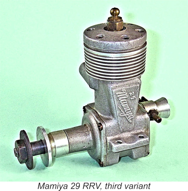
A further change was the form of the cylinder head. The additional machining step required to diametrically reduce the lower face of the head above the seating face was now dropped. The inference is that the makers had found that cooling was not an issue with this design and the extra cooling surface below the head was not necessary. Accordingly, they elected to save themselves another manufacturing step. The relatively high compression ratio noted above in connection with the earlier variant was however retained. In all other respects, the two variants were identical. At present I have no means of determining when these changes took place. All that I can report at present is that surviving examples of the first variant appear to outnumber those of the second variant by a substantial margin. The Mamiya 29 FRV Glow-Plug Model - Third Variant At some indeterminate point in time, probably towards the end of Mamiya model engine production, a third and apparently final variant of the FRV glow model was produced in relatively small numbers. This is unquestionably the least common Mamiya 29 FRV model, and I‘m fortunate indeed in being able to describe it on the basis of an actual example which I have on hand.
In this third model of the engine, the most obvious change was the means of cylinder retention. The welds fore and aft that had previously been used were now eliminated – instead, the cylinder was retained in place by the conventional use of three long screws which passed through the head and then through holes in the cylinder fins to engage with tapped holes in the main crankcase casting. The other three head retaining screws continued to be of the short variety which engaged with tapped holes in the upper cylinder flange as they had done previously. The die for the main crankcase casting was slightly modified to facilitate the production of this variant. The two shallow “bosses” fore and aft which had previously accommodated the cylinder retaining welds were eliminated and two small expansions were cast into the case, one on either side of the bypass passage, to accommodate two of the three long cylinder hold-down screws. The third long hold-down screw was accommodated through the inclusion of a substantial cast-in column in the middle of the exhaust stack, replacing the thin brace which had sufficed previously. This system had the advantage of facilitating the complete disassembly of the engine and replacement of parts as needed. Its one disadvantage was that it introduced hold-down stresses and consequent potential distortion into the cylinder walls. Unless repairs are required for continued use, it would seem advisable to leave such an engine well alone following break-in, since dismantling and re-assembly could result in re-distribution of hold-down stresses and consequent dimensional changes in the bore, especially given the very thin cylinder walls employed.
The cylinder head was apparently based upon the same casting as that used on the final model of the Mamiya 29 RRV model (see below), but the vertical relationship of the head to the piston at top dead centre yielded a noticeably lower compression ratio than that used on the two previous FRV variants. The difference is clearly detectable simply by “feel” alone. By rough volumetric measurement, the compression ratio of this model is of the order of 7 to 1, indicating that it was intended either for use on hotter fuels or (more probably) that it was intended to be operated at lower speeds in a control line stunt context. In other words, the Mamiya designer had finally recognized the engine’s true métier and had adjusted the design accordingly. This lower ratio is actually quite typical of stunt engines of the day, being used by Enya and others. The engine certainly needles far better and would be a superior engine for control line stunt in this configuration. It is also more user-friendly to start. Peak power would probably be down a little, but the Mamiya was not lacking in that department in any case and the porting modifications would likely have recovered at least part of any losses. On the test bench, the engine remains a quite lively performer.
As with the companion third-model .29 RRV model (see below), the head on this variant of the FRV design was left in its matte-finished configuration rather than being given a final polish as with previous models. In addition, the black paint formerly applied to the front and rear covers was no longer in evidence. This was a logical step - that paint did not stand up well to the rigors of frequent use and quickly ended up looking rather tacky in any case! Finally, the engines were no longer supplied with back tanks, although the option of fitting a tank was preserved through the retention of a tapped spigot in the backplate. This was a completely logical change - no-one was using back tanks on engines of this displacement by the mid 1950’s, with even back-tank die-hards Fuji dropping the component on their .29 and .35 cuin. models as of 1955. Minus the tank, the engine weighed in at a relatively light 63/8 ounces (181 gm.) Overall, the result was an attractive, compact and light .29 cuin. glow-plug motor having a good “sport/stunt” performance by the standards of its day. In my personal opinion, it was the most useable version of the Mamiya 29 FRV model. It was a definite improvement over the previous variant, hence deserving to do well in the contemporary marketplace. However, sadly that was not to be. Examples of this variant are very rarely encountered today, even in Japan, and it would appear that this final model was produced in relatively small numbers prior to production ceasing altogether. Another sad case of too little, too late…………………. The Mamiya 29 RRV Glow-Plug Model - First Variant
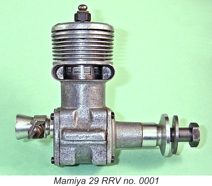
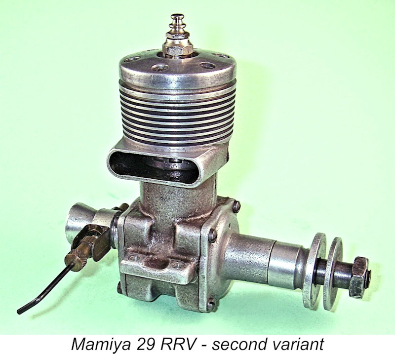
Unlike their .099 and .29 cuin. FRV companions, none of the known variants of the Mamiya 29 RRV featured pressure die-cast components. Rather, gravity die-casting appears to have been used throughout. This implies that relatively limited production of this model was envisioned all along, and in fact the initial variant was almost certainly produced in extremely small numbers as a racing “special” created solely for the purpose of promoting the Mamiya name through competition success in the hands of Japanese modellers. It was probably never offered as an “over the counter” item. This initial version was the sole contemporary Mamiya 29 to be assigned serial numbers - I’m lucky enough to own engine number 0001 of this ultra-rare series, and engine number 0003 appeared on eBay some time ago. These are the only two examples of my personal acquaintance.
The pattern used for the revised main crankcase casting of the RRV model provided for the machining of cooling fins on an alloy cylinder barrel which was cast integral with the lower case and extended all the way up to the base of the cylinder head. This arrangement naturally required the use of a drop-in steel liner. In adopting this layout, the designer followed the established pattern which had been used on the original Mamiya 60 and was still a standard feature of McCoy, Dooling and ETA racing motors as well as the Enya range, among others. The Mamiya 29 designation was cast in relief onto the bypass, just as on the 29 FRV model, but the style of the script was very different - in particular, the number 29 appeared in quite large ciphers beneath the Mamiya name. This was to be the sole Mamiya model to bear this style of model designation.
It’s interesting to note in passing that the displacement of the engine was slightly in excess of the maximum allowed under the American Class B rules, conforming instead to the 5 cc limit used in Japan and Europe. The implication is that export sales of this model were not envisioned, with the displacement being maximized to enhance the engine’s chances in Japanese competitions against US opposition. The piston followed the conventional racing engine layout, being made of light alloy with two well-fitted cast-iron piston rings. The transfer and exhaust ports through the The un-finned cylinder head on this engine differed slightly in appearance from that used on the FRV models, having a somewhat lower profile. A gasket set into an annular recess was used to ensure a seal. The head thickness was only sufficient to accommodate a short-reach glow plug, which was centrally located. The combustion chamber was basically a simple shallow dish shape with a curved slot machined into it to accommodate the piston baffle This latter arrangement was to appear on all versions of the Mamiya 29 RRV.
At first sight the use of a single ball race might appear a little odd for a racing engine, but in fact there was sound reasoning behind it. The fact has long been recognized that front ball races actually contribute relatively little to engine performance since they are located at the most lightly-loaded end of the shaft (assuming that the prop is well balanced). It’s also a fact that while a twin ball-race shaft undeniably does offer some potential for performance enhancement, all of the potential benefits can be undone if the bearing alignment isn’t perfect.
A ball race at the loaded (rear) end of the shaft does far more to absorb radial loads, offset friction losses and minimize wear than a front race. In addition, the need to accommodate a second ball race inevitably adds extra weight to the engine, and it is weight which in reality contributes little to the engine’s effectiveness. Finally, the extra ball race represents an increase in cost for relatively little return. An interesting detail is the presence of a small cast-in “dimple” on the front face of the main bearing housing. This was evidently included to ensure that the housing was re-installed in the same orientation if the engine had to be dismantled for servicing, as frequently happens with racing engines. It is generally (but not always) located in an upward orientation. Since the housing appears completely symmetrical, this provision must surely have been included to maintain established wear patterns within the bearings. A very thoughtful detail, which was to be carried right through the Mamiya 29 RRV series.
The disc valve on this original model of the Mamiya 29 RV was made of a reinforced plastic material. A noteworthy feature is the absence of any retention arrangement for the disc - it is mounted on a simple steel spigot, total reliance being placed upon crankcase pressure and surface tension to keep it in contact with the backplate. Minoru Sato appears to have been one of the first designers to appreciate the practicality of such a configuration, which was carried through all of the Mamiya RRV racing models. Being a bit nervous about that 3 mm gudgeon pin, I’ve never subjected engine no. 0001 of this type to a full-blown test, but I can confirm that it starts and runs very well indeed. The Mamiya 29 RRV Glow-Plug Model - Second Variant
Coupled with the ongoing use of a spraybar fuel system, the continued use of a single ball race, while entirely logical for reasons stated earlier, implies that the engine may have been intended as a high-performance “sports” engine or an introductory “budget” competition engine rather than an all-out racer. There is further support for this possibility in terms of the engine’s internal design specifications. The cylinder port timing was By volumetric measurement, the compression ratio is 8 to 1, slightly less that that used on the companion FRV model. Again, this is a relatively modest compression ratio for an engine intended for racing service. It may be that the designer anticipated the use of higher-nitro fuel in this version and adjusted the compression ratio accordingly. Or it may equally well be that the engine was indeed intended for high-performance “sports” use, in which case a lower compression ratio would make perfect sense. The induction timing is more typical of normal racing engine practise, with a duration of 180 degrees. The companion FRV model has a similar induction period, but the disc valve on the RV model opens and closes 5 degrees later (45 degrees ABDC to 45 degrees ATDC) than on the FRV model. The disc continued to be made from reinforced plastic, with the same absence of any positive means of retention on its spigot. Another detail which was carried over from the FRV models was the incorporation of a very small period of sub-piston induction - around 10 degrees either side of top dead centre.
This variant retained the ringed alloy piston of its predecessor, but the designer had by now decided that the gudgeon pin needed to be enlarged. The gudgeon pin in this variant was of 4 mm diameter tubular steel, with aluminium end pads. This matched the similar component used in the contemporary FRV model. A more significant change in this variant was the internal geometry of the engine. The bore and stroke were brought into line with those of the companion FRV model, perhaps to facilitate the used of some common components like the cylinder head, con-rod, gudgeon pin, etc., as well as to allow the use of common tooling for the manufacture of certain components. Measured bore and stroke were now the same as the FRV version at 19 mm and 17 mm respectively for a displacement of 4.82 cc (0.294 cu. in.), thus increasing the bore/stroke ratio somewhat and also bringing this model into conformity with the American Class B rules. It may be deduced from this change that the company was now considering the possibility of sales of this model on the US market.
We would certainly expect a measurable performance increase from these features, but nothing really spectacular. This unquestionably leaves one’s mind open to the notion presented earlier that this engine was intended more as a high-performance “sports” model or “budget” competition engine than as an all-out no-holds-barred racing unit. The main casting used in this second variant differed from that used in the earlier “specials” in that it now bore the familiar Mamiya 29 designation in the same ciphers as on the companion FRV models. In addition, the mounting lugs had shallow depressions on their upper surfaces between the mounting holes. A green coloration was applied to the main casting, possibly by dye-anodizing. This treatment does not wear well, fading rapidly to a brownish hue and then disappearing altogether. The original coloration has been lost in the case of two of my three examples, although there are residual traces. The other example retains much of its green coloration, which is unquestionably original.
The illustrated un-numbered engine weighs in at 174 gm (6.14 ounces), a few grams more than the earlier variant. Numbered example no. 2712 has been very capably modified by an owner who clearly had visions of using it in a control-line speed application. It has been fitted with what appears to be a McCoy intake venturi of substantially larger bore than the standard Mamiya component. It has also been equipped with a Super Tigre needle valve assembly - one of the best in the business for speed control-line work. Finally, its stack has been very neatly contoured, presumably to fit a helmet cowl. The engine starts very easily and runs with noteworthy vigor. The quality of construction continued to be of the highest order throughout. On these two apparently little-used examples, all fits are beyond reproach, and the compression seal provided by the twin-ringed piston would do credit to any diesel. The Mamiya 29 RRV Glow-Plug Model - Third Variant
This model was again very similar to its predecessor, but there were a number of detail changes of some significance. Firstly, the exhaust and transfer ports were both moved higher up the cylinder wall. It may be recalled that this same step was taken (most likely concurrently) with the companion FRV model to produce the final variant of that model also.
Another difference of some significance was the replacement of the plastic disc valve with a thin steel disc having a protruding drive spigot which located quite snugly in a hole drilled concentrically in the crankpin. The disc was mounted on a steel screw. The engine's induction timing was unaffected by this change. Most intriguingly, the fit of the steel rotor on its mounting screw in the illustrated example is quite slack - there’s a detectable amount of radial “wobble” on the central bearing, even though this particular engine has done little or no running. This is presumably intentional to accommodate any slight location errors between the respective centrelines of the main crankshaft and the rotor bearing. Since the driving spigot is very snugly located in the crankpin, there should be no real issues arising from this feature - it just seems a little odd given the very high standard of fitting of the rest of the engine. The rotor mounting screw presumably has a left-hand thread to prevent unscrewing during operation, but I can’t confirm this - careful attempts to shift it by fair means were unavailing.
Apart from its excellent wearing qualities, the use of a thin flat rotor eliminated the considerable crankcase volume represented by the cut-outs and cast-in voids present on a conventional cast A further change was in the length of the intake venturi. That used on the previous variant had an overall length of 21.5 mm, which was increased to 24.0 mm in the revised model. Most of this length was in the threaded portion of the venturi which continued to be screwed into the backplate using a 9 mm x 0.75 mm thread with a locking ring. The spraybar-type needle valve assembly was located at exactly the same distance as before from the open end of the venturi, meaning that it was a little further from the disc valve than before. It’s presently unclear why this change was made - perhaps simply to move the needle further away from the engine body for easier operation with the needle set in a vertical orientation?!? If so, this would represent further evidence of the maker’s intention to market this engine as a “general purpose” unit rather than as a racing special. In a racing application, the needle is usually aligned horizontally at 90 degrees to the bore. Consequently, venturi length is not an operational issue in such a case. Overall, we would expect to see a modest performance increase as a result of the various changes documented above. Unfortunately, my reluctance to run this apparently pristine example prevents me from commenting further on the basis of actual tests.
All castings were presented in an attractive matte finish. This included the cylinder head, which up to then had received a brush-polished finish. It may be recalled that a similar matte finish was applied to the head of the companion final FRV model described earlier - a further indication that the two models were produced concurrently. Presumably the use of as many common components as possible was continuing. Measured bore and stroke remained the same as those of the previous RRV model and the contemporary FRV version at 19 mm and 17 mm respectively for a displacement of 4.82 cc (0.294 cu. in.). The compression ratio too was unchanged from that of the previous RRV model at a measured 8 to 1. The checked weight of this variant was up to 188 gm (6.63 ounces). Doubtless the steel disc accounted for part of this, but one suspects that there must be more to it than that ………. perhaps the crankshaft was beefed up somewhat?!? The quality of construction of this variant continued to meet the very highest standards throughout. The compression on this apparently unused example is well up to the best diesel standards, and all bearings are perfectly fitted. The engine turns freely but with no trace of play anywhere apart from the slight "wobble" in the disc valve bearing, which is probably intentional. If the listing of the “World’s Model Engines” from the 1958 publication “Model Aero Engine Encyclopaedia” is to be believed, this final version of the Mamiya 29 outlasted the earlier FRV model. Certainly, that listing includes only the RRV model, no mention being made of the FRV version. It thus appears that this latter variant may have represented a final attempt by Mamiya to gain some respectability in the 29 performance stakes. Conclusion Well, there you have it – all that I’ve been able to learn about the .29 cuin. model engines which were marketed under the Mamiya trade-name. These were very fine engines which did great credit to their designer Minoru Sato. I hope that some of you found something of interest here! _________________________ Article © Adrian C. Duncan, Coquitlam, British Columbia, Canada First published March 2026 |
 This is the third article in my series of detailed reviews of the various displacement categories which formed part of the Mamiya model engine range from early post-WW2 Tokyo, Japan. I’ve covered the history of the range in general in a
 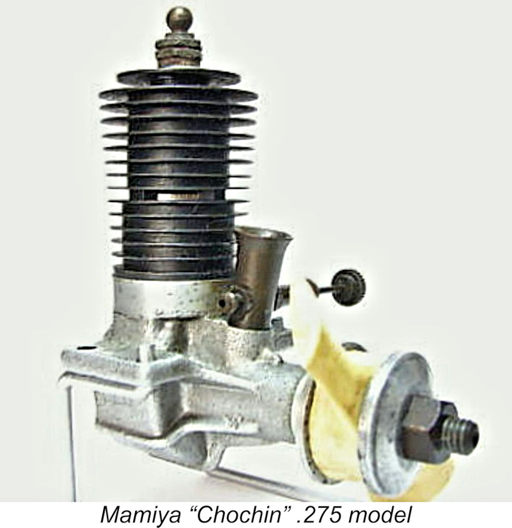 As far as I’m presently able to determine, Tokyo Hobbycrafts entered the .29 cuin. category in 1948 with a radially-ported reverse-flow scavenged crankshaft front rotary valve (FRV) glow-plug unit known as the Mamiya “Chochin” .275 cuin. model. This was accompanied by an identically-configured 0.097 cuin. offering, of which much more
 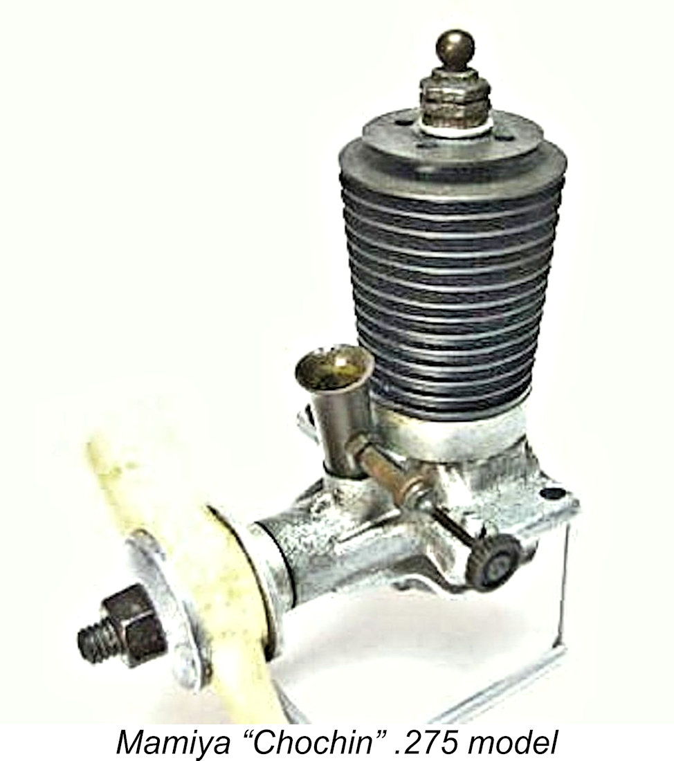 At the time of writing, I didn't have an actual example of this very rare engine available for examination. My knowledge is thus confined to a series of images extracted from the web plus extrapolation from an example of the companion .097 cuin. model which is available for direct inspection.
 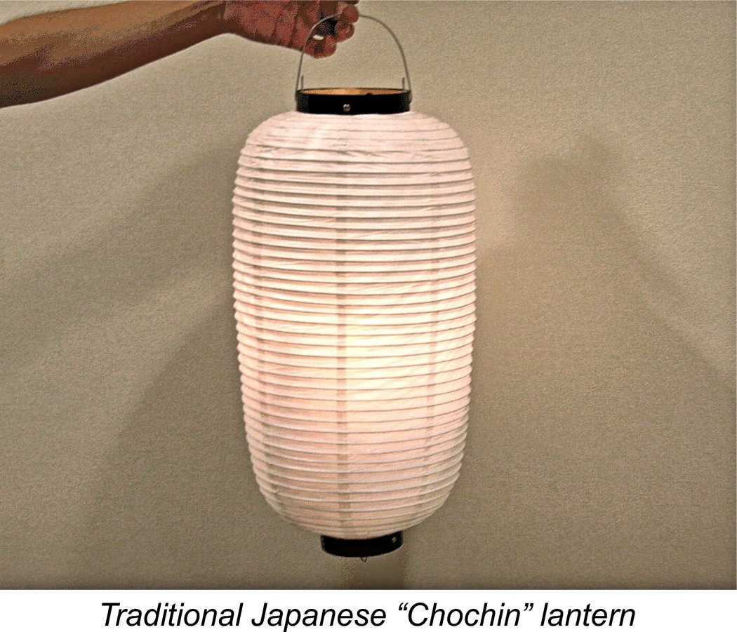 In adopting this configuration, these engines harkened back to the pioneering era of Japanese model engine design. During that period, Japanese model engine design was dominated by a minimalist philosophy in which a feature was only included if it contributed to the engine’s performance or structural integrity. Components were designed to do their job, and no more. External appearance and styling were very much secondary considerations. This philosophy contributed to lower production costs than would otherwise be the case.
 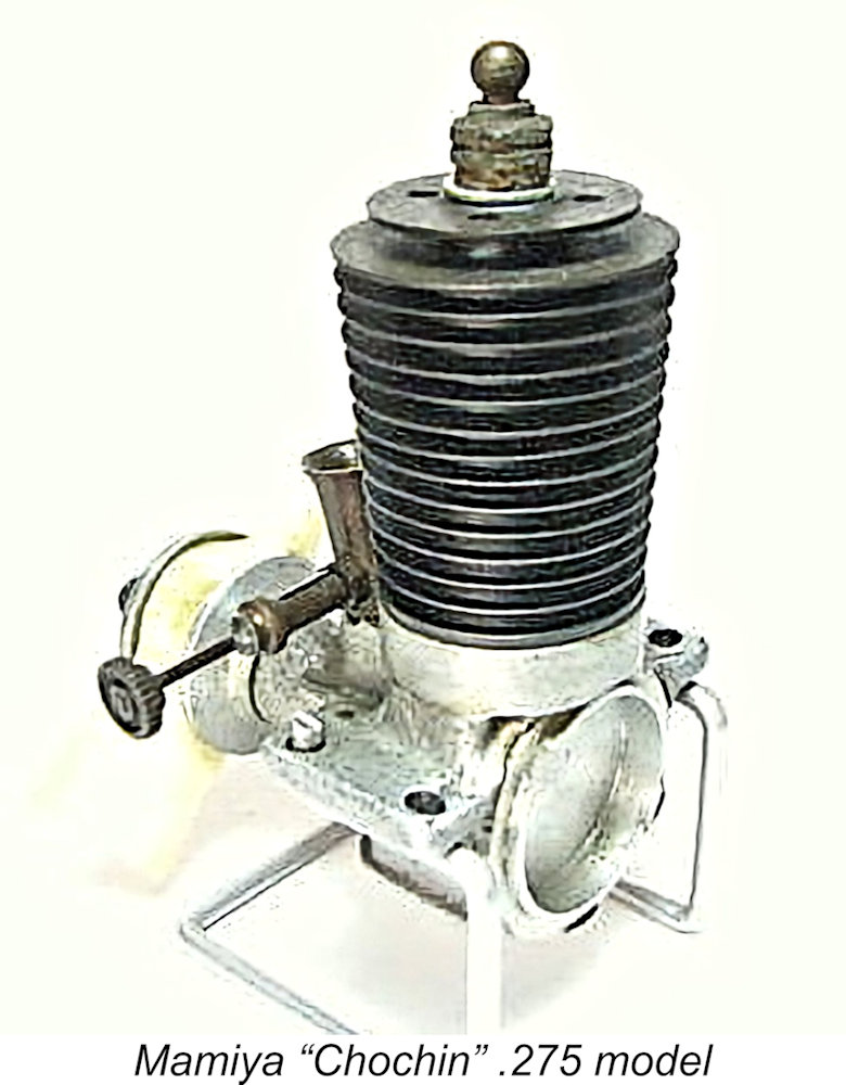 Not having an actual example available for direct examination, I can’t report on the bore and stroke measurements for the .275 cuin. model now under discussion. The companion .099 model featured over-square nominal bore and stroke measurements of 13.0 mm and 12.0 mm respectively for a nominal displacement of 1.59 cc (0.097 cuin.). If a similar bore/stroke ratio was used for the larger engine, we might postulate dimensions of 18.3 mm and 17.0 mm respectively for a nominal displacement of 4.47 cc (0.273 cuin.). But this is pure conjecture - I could really use some measurements taken from an actual example. Any volunteers?!?
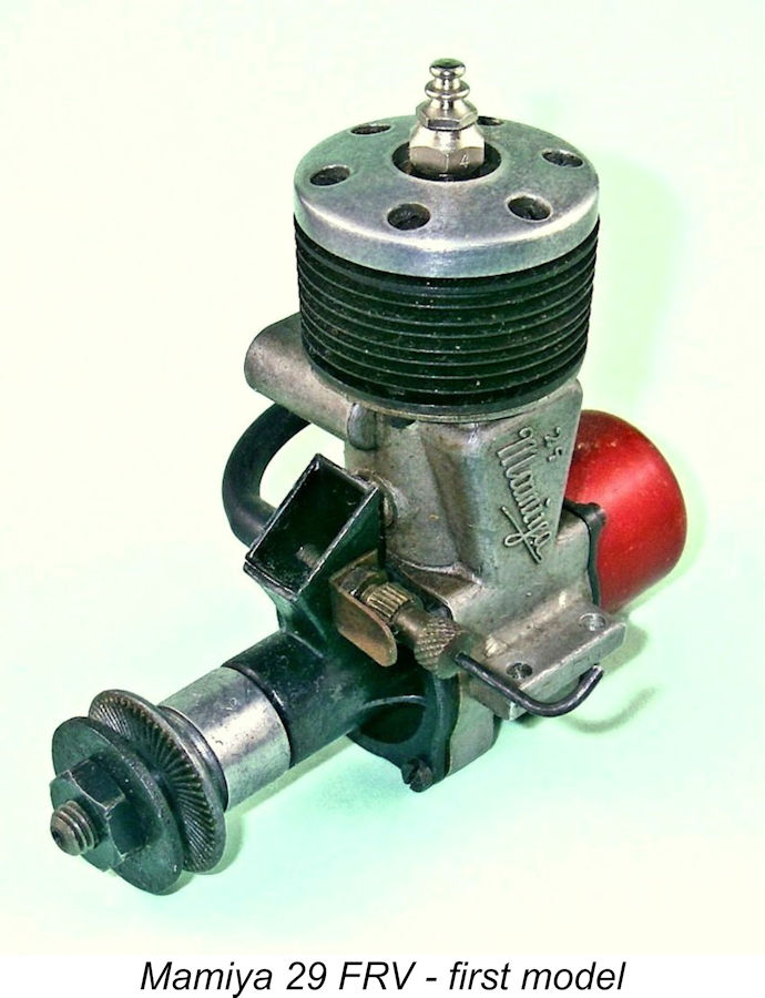
 Crankshaft front rotary valve (FRV) induction was once again used, but the new model featured a separate bolt-on main bearing housing, the intake being integrally cast. The intake was somewhat unusual for the time in question in having a tapering rectangular section with a square base rather than the more usual round configuration. The induction port in the crankshaft was milled to a rectangular section and was of adequate length.
 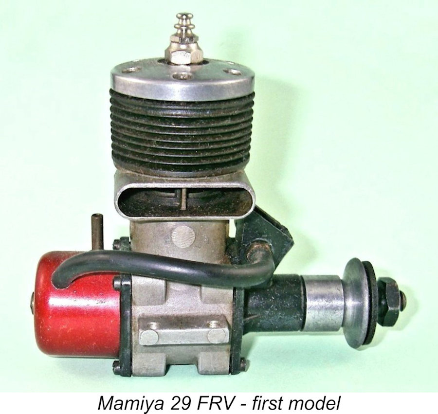 The cylinder port timing was somewhat less generous - the exhaust port opened and closed at 60 degrees either side of bottom dead centre for a rather conservative total duration of only 120 degrees, while the transfer port lagged behind the exhaust by 10 degrees for a total opening period of a mere 100 degrees. However, the ports were very generously sized, so these relatively short periods were doubtless quite sufficient for operation at the speeds envisioned. The bottom edge of the exhaust port was set sufficiently low that a short sub-piston induction period of some 10 degrees either side of top dead centre was incorporated.
 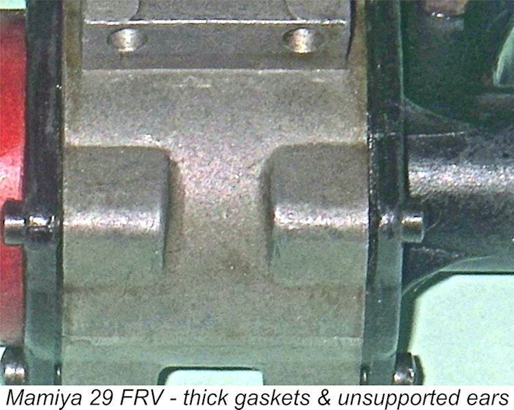 To deal with this, one might reasonably expect that Tokyo Hobbycrafts would have modified either the backplate or the main casting to increase the amount of clearance between the rear of the crankpin and the inner face of the backplate to the point where rearward movement was limited (as it should be) by the prop driver bearing upon the front housing. However, they did not do this - instead, they simply added extra gaskets both at the front and the rear until sufficient clearance was obtained. In effect, they used the gaskets as shims to obtain the correct clearance. Rather a “band-aid” approach, it must be said! One of my examples had no fewer than five such gaskets behind the front cover! Moreover, they were needed to maintain the required clearance ............
 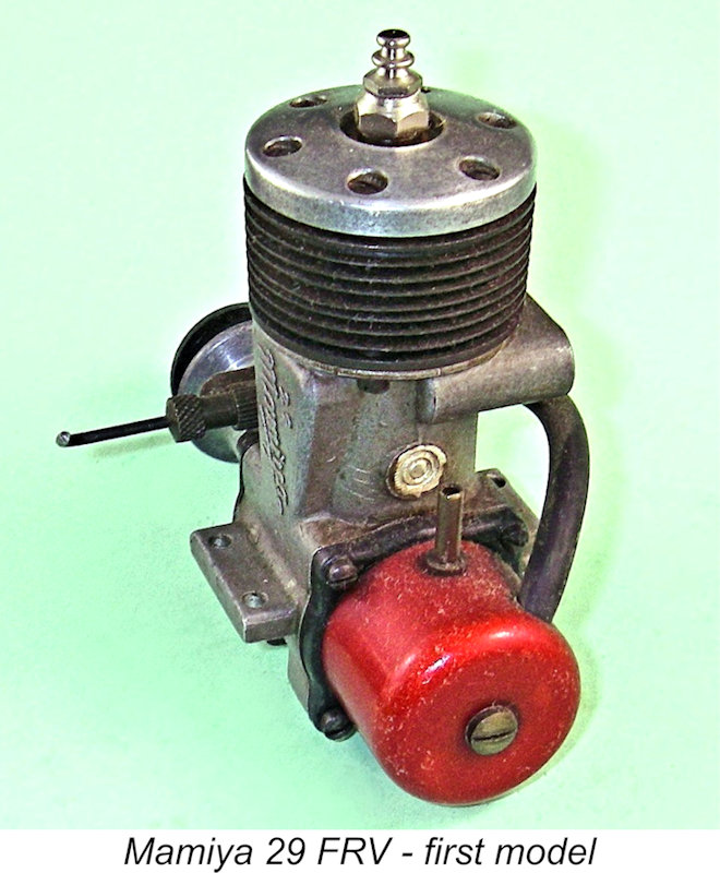 Hence the degree to which the retaining screws could be tightened down without bending or even breaking the hold-down lugs was somewhat limited. Not really an issue in the case of the rear cover, but the front cover was of course quite heavily loaded during operation and would normally be tightened down quite firmly. This was not possible with the Mamiya design, and the security of this cover might consequently have become problematic over time. Certainly, the tightness of these screws would have required constant checking in service, especially given the tendency of thick gaskets to “set” over time. A point for present-day owners to be aware of ………… and it explains the examples which occasionally turn up today with bent or broken lugs on the front and rear covers.
 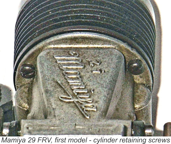 Both the slightly offset location and the small size of these screws are inconsistent with the notion that they were intended to be relied upon as a functioning element of the cylinder retention system. Indeed, the upper flange of the crankcase through which the screws pass is too thin to sustain any great hold-down forces without distortion. It appears far more likely that the primary purpose of the two screws was to serve as a convenient means of compressing the base seal and holding the cylinder securely in place at its correct angular alignment pending the completion of the spot-welding process noted above. In addition, the screws would provide back-up in the event of the failure of the welds in service. A loose cylinder flying off one of these engines while running would represent a considerable potential hazard!!
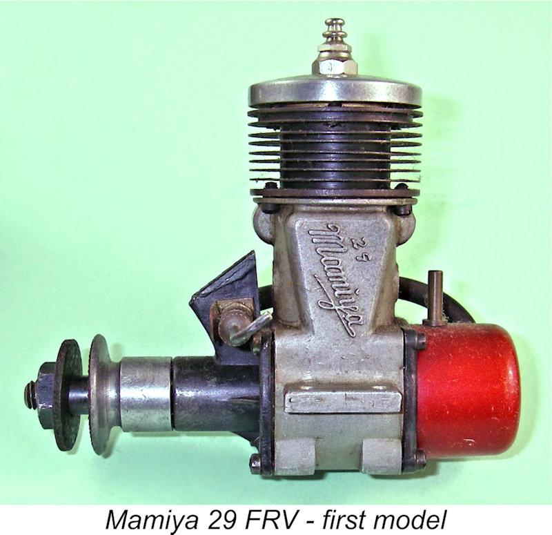
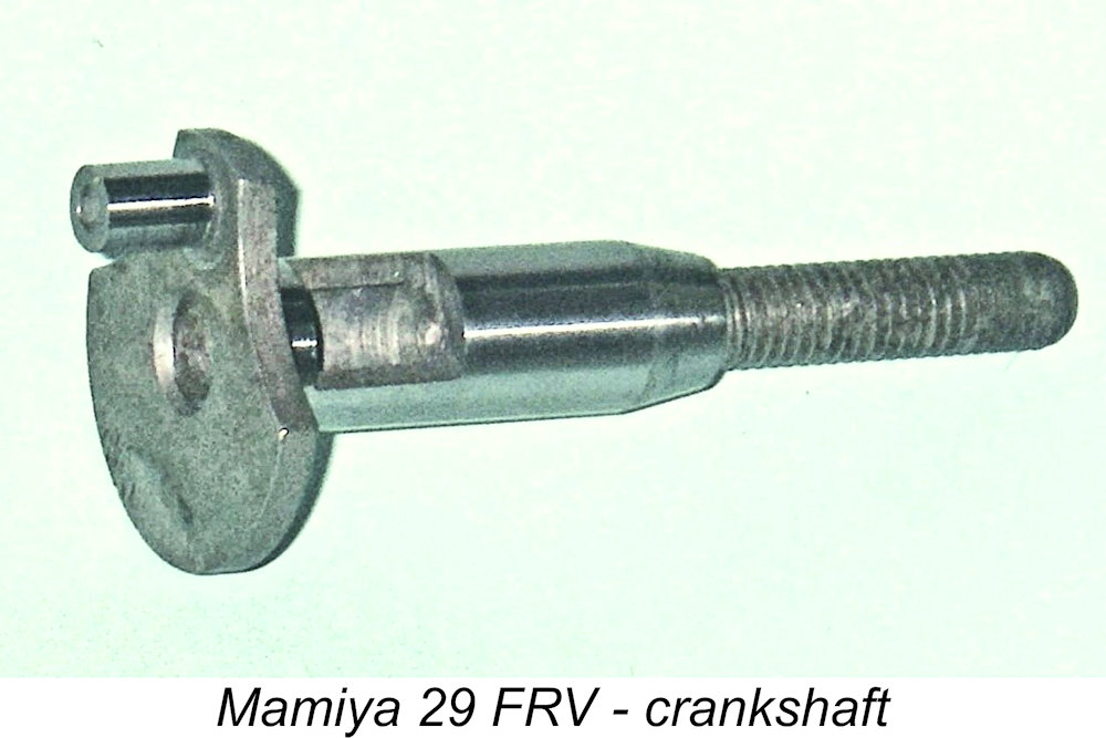 The crankshaft ran in a bronze bushing and featured an unusually thin web for an engine of this displacement - apparently a hold-over from an earlier era. The crank-web disc was machined away on both sides of the 5 mm dia. crankpin for counterbalance, and the crankpin itself was drilled right through at 2.5 mm dia. to further lighten the crankpin side of the web. Main journal diameter was 10 mm, with the central gas passage having a diameter of 6.5 mm.
 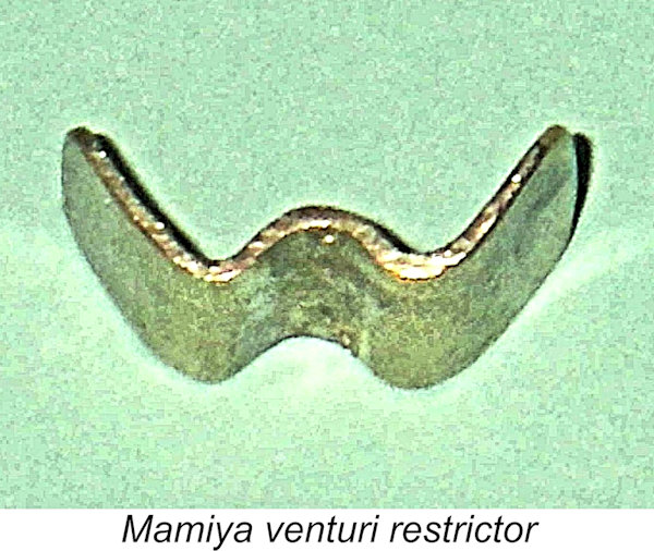 To get around this difficulty, the Mamiya designer adopted a very neat alternative approach, using a piece of thin brass sheet cut to the same lateral width as the intake interior and folded into a “W” shape, much like a tiny cookie cutter. This was inserted vertically into the intake with the two outer “legs” at the front against the intake’s inner wall, and the unit was retained in place simply by the spraybar passing through the central “V” on the opposite (rear) side of the “W”-shaped insert between the two “legs” on that side. This effectively blocked the portion of the intake forward of the spraybar, leaving a clear rectangular area of intake behind the spraybar. The single jet hole in the spraybar was placed at the narrowest point of the resulting constriction, a point which is worth confirming before attempting to run one of these motors today. If a more free-breathing intake set-up using pressure feed was required, all that was necessary was to remove the spraybar and restrictor and then re-install the spraybar on its own. Neat!
 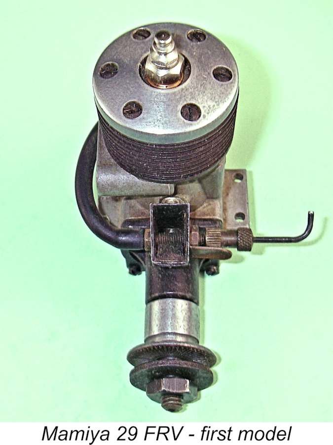 The restrictor actually served another purpose in addition to promoting better suction, and I suspect that the designer had this secondary effect very much in mind. The insert also provides much-needed support to the rather thin side walls of the venturi. These flat surfaces are extremely prone to distortion when the spraybar is tightened up, and the insert provides the necessary support by acting as the “meat in the sandwich”, limiting the distortion potential inherent in the design. Hopefully the accompanying image will clarify the function of this fitting.
 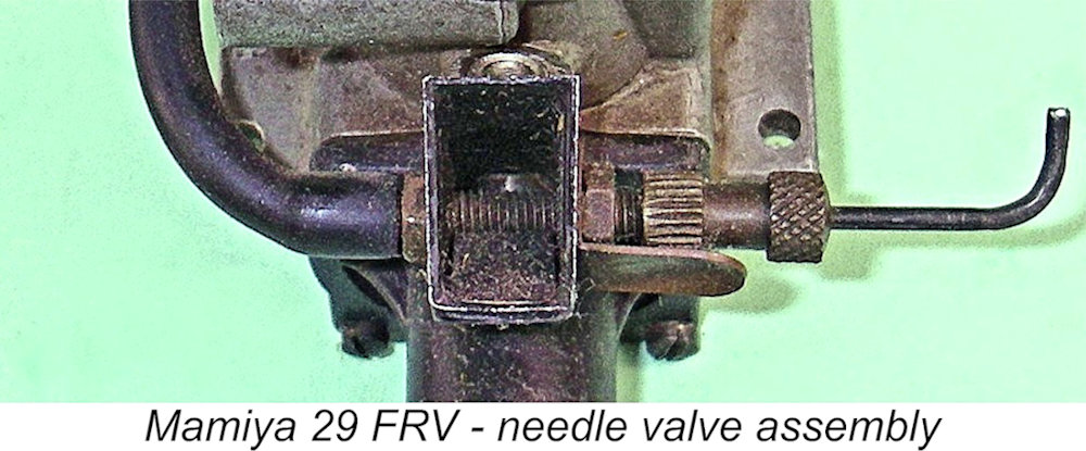 Needle tension was provided by a simple double-sided brass spring clip acting on the grooved portion of the thimble. Very like a standard universal assembly, and the sad fact is that this has led some owners to assume that the needle valve assembly on their examples was a later “universal” addition and to discard it on the assumption that it was not original. A pity, and quite unnecessary since the assembly just described works very well.
 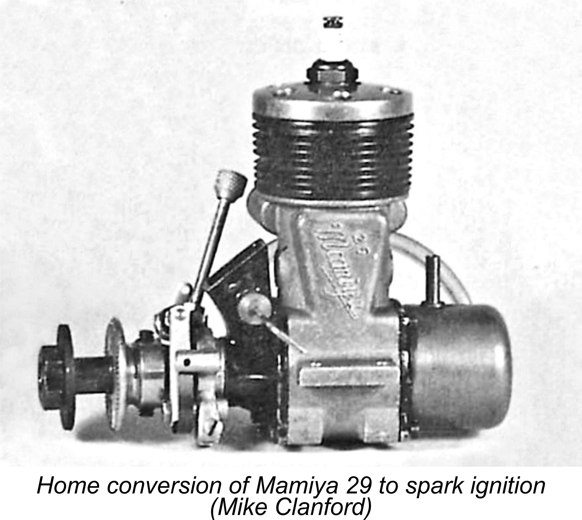 By this time, of course, the glow-plug had more or less completely supplanted spark ignition as the ignition system of choice, at least in the Asian and North American markets. In this context, I consider it necessary to dispel what I sincerely believe to be a significant piece of widely-disseminated misinformation regarding the loop-scavenged Mamiya 29 model. This is the issue of the existence of a factory-built spark-ignition version of this design.
 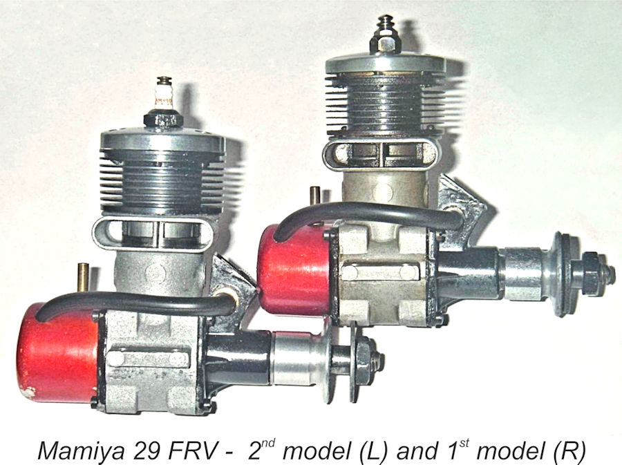 Whatever the motivation, the second variant of the Mamiya 29 did not feature the two subsidiary cylinder hold-down screws of its predecessor. And this was not all - the new variant also featured cooling fins which were turned considerably thicker than those of the first variant described earlier. Presumably experience in the field had convinced the manufacturers of the need to provide thicker fins which were less prone to accidental damage. Since both the number of fins and the cylinder height were unchanged, the extra fin thickness was accommodated through a decrease in the width of the cooling grooves between the fins. A similar change was applied to the companion .099 model, presumably at around the same time.
 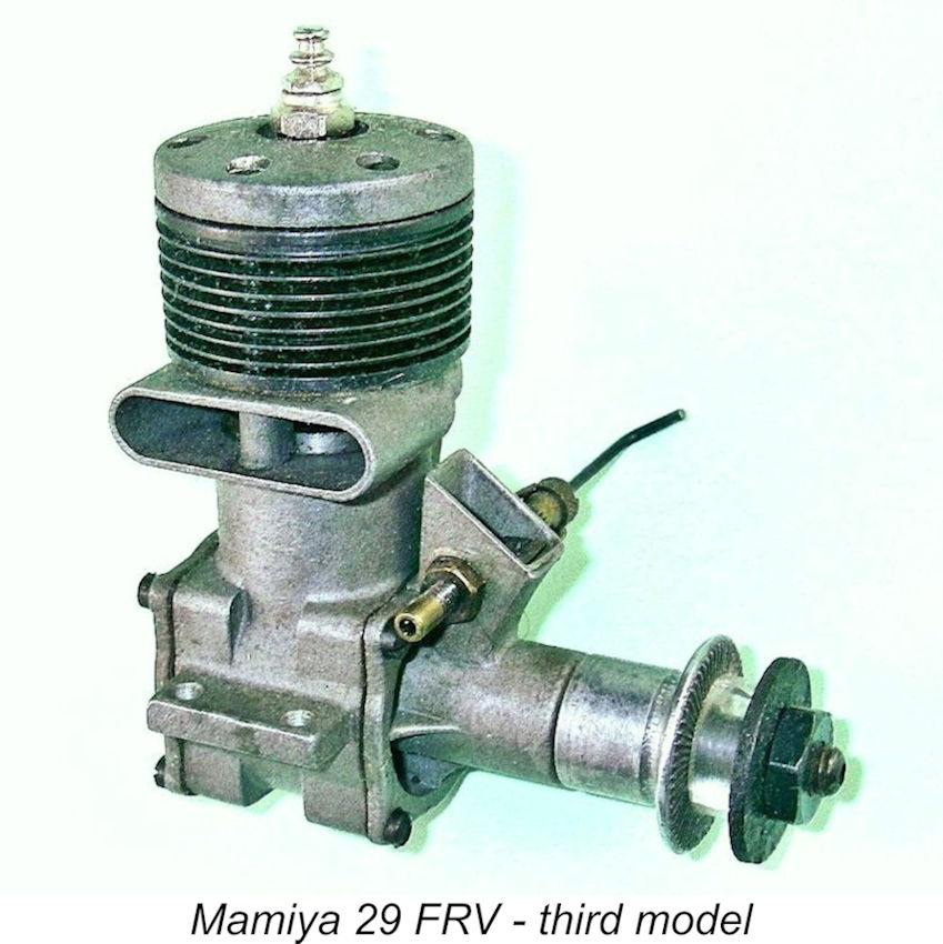 It would appear that by the time in question Mamiya had finally grasped the limitations imposed by their continuing use of welded construction for the retention of the cylinder. I’ve alluded previously to the fact that any requirement to replace the piston/cylinder or the main crankcase casting forced the owner to buy a complete piston/cylinder/crankcase assembly instead of simply purchasing the part(s) requiring replacement.
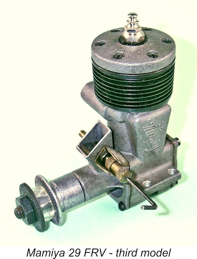 The cylinder was slightly modified from that of the previous variant by having both the exhaust and transfer ports moved slightly higher up the cylinder. This resulted in an increase in the total exhaust opening period from 120 degrees to 130 degrees (65 degrees either side of bottom dead centre), with a parallel increase in the transfer period from 100 degrees to 110 degrees (55 degrees either side of bottom dead centre). The change also eliminated the sub-piston induction which had been a feature of earlier variants.
 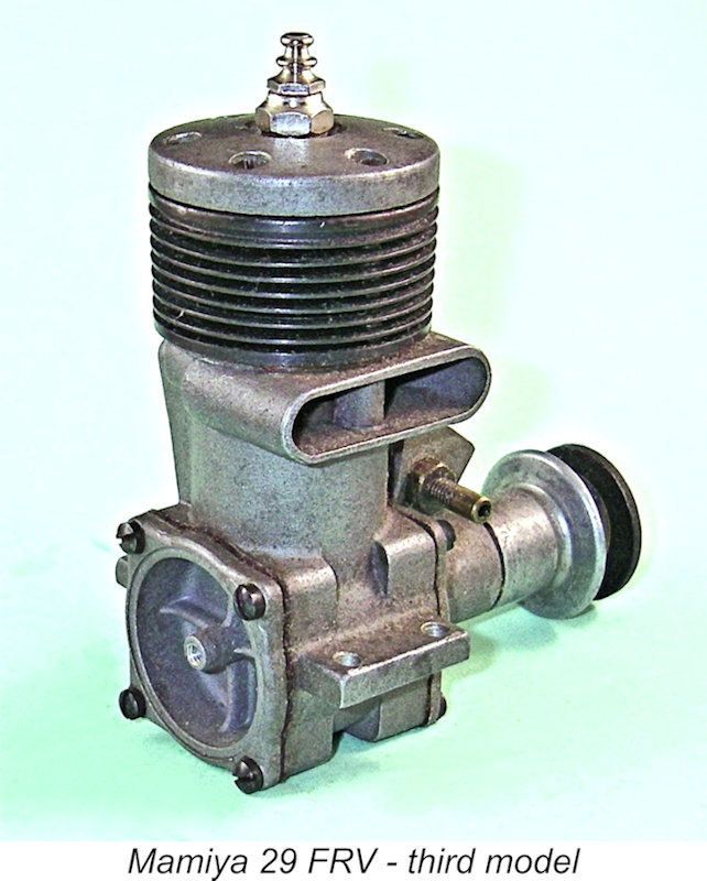 In all other respects, the revised model was essentially identical to the two earlier variants in terms of its design and construction. However, the selling price of the Mamiya range by comparison with its competitors had seemingly become an issue by this time - indeed, the marque may well have been moving into “survival mode”. Certainly, a number of measures were taken in an evident attempt to manage production costs.
 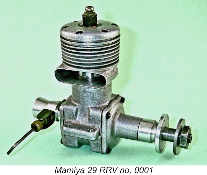 During the early to mid 1950’s, Tokyo Hobbycrafts produced a succession of rear disc-valve “racing” versions of their Mamiya 29 glow-plug model. These quite rare engines are seldom seen outside Japan, actually being far from common even there. It actually appears that relatively few were made. Fortunately, I have direct access to no less than five examples of this model which cover all three known variants. Accordingly, I’m able to describe this interesting design in some detail.
 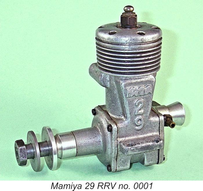 The adoption of gravity die-casting for the case of this variant was probably driven initially by the fact that the required casting was significantly different from that of the companion FRV model and the use of pressure die-casting was not justifiable economically. In this context, it is perhaps significant that no version of the FRV model is known to have been based upon this casting, implying that its use was intended all along to be limited to the low-production RRV models. Accordingly, these cases were produced in relatively small numbers.
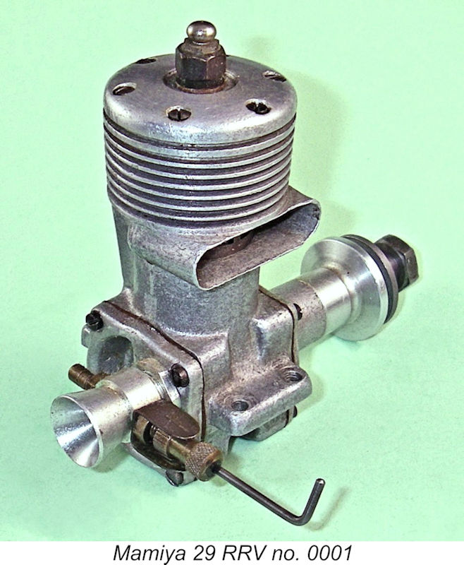 The employment of cooling fins which were machined integrally with the main casting naturally eliminated the requirement for the use of welding to retain the cylinder in place. The unfinned drop-in liner was now conventionally retained by an alloy cylinder head secured to the main casting by six screws. The measured bore and stroke of the illustrated example are 18.8 mm and 18.0 mm respectively for a displacement of 4.99 cc (.304 cuin.). The engine’s checked weight is 171 gm (6.03 ounces) - very light for a 5 cc racing engine.
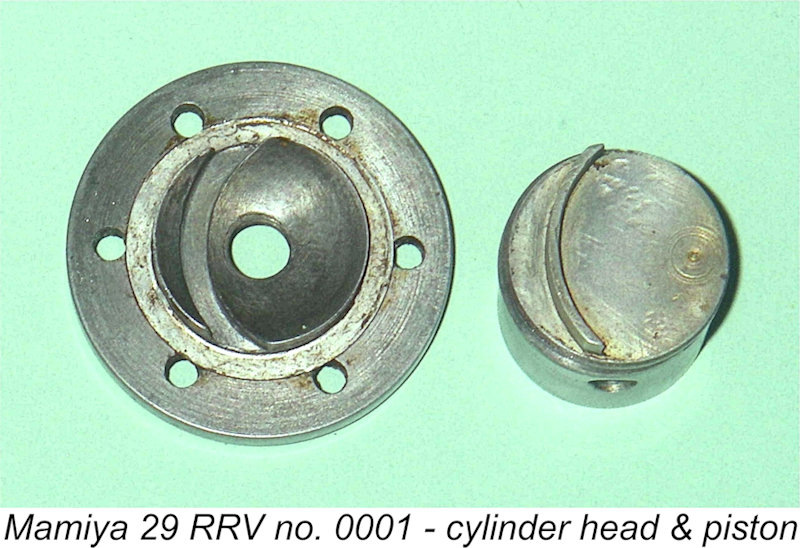
 The front and rear covers of this model were also gravity die-castings, almost certainly for similar reasons to those which motivated the use of similar production methods for the main case - they were used on no other model of the Mamiya 29. As with the Mamiya 60 RRV model described elsewhere, the 29 RRV used a single ball bearing mounted at the inboard end of the shaft. The front housing looked pretty much like a down-scaled version of the 60 RRV front end.
 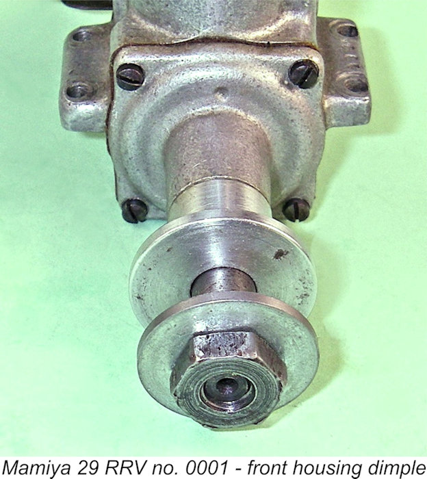 The prominent English model engine designer Gig Eifflaender of
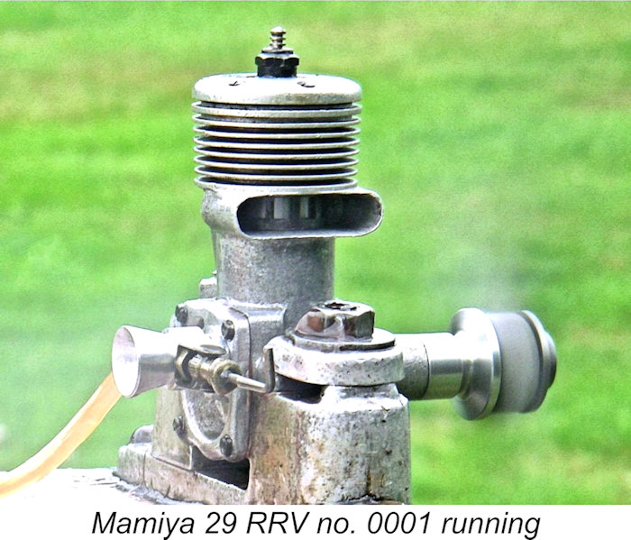
 At some point after the manufacture of the serial-numbered “specials” described above had been terminated, Tokyo Hobbycrafts released limited numbers of a “consumer” version of this model, the majority of which did not bear serial numbers. This was externally very similar to the “special”, and it’s actually possible that the “specials” were in effect factory prototypes released to a select few Japanese modellers for field testing prior to the release of a limited-production “consumer” model. Of my three examples of this model, only one bears a serial number – 2712. The significance of this is unknown.
 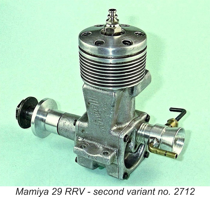 surprisingly little changed from that of the companion FRV model. The exhaust opens and closes at 60 degrees either side of bottom dead centre for a total duration of only 120 degrees, just as in the FRV model. The difference is that the transfer opens only 5 degrees later than the exhaust (rather than 10 degrees in the FRV) for a slightly increased total duration of 110 degrees. These are very conservative figures indeed for a “racing” engine, and the sole difference between this design and the FVR model is the fact that the transfer period is some 10 degrees longer.
 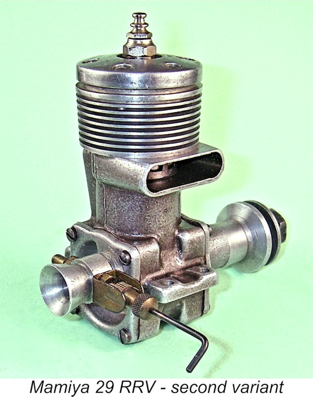 The screw-in venturi was apparently identical to that used on the preceding “special”. It retained a nominal throat diameter of 7.5 mm, allied to the same 3.5 mm spraybar-type needle valve assembly as used on the companion FRV model. The venturi installation thread remained unchanged at 9 mm x 0.75 mm, with a locking ring continuing to be used for security of orientation.
 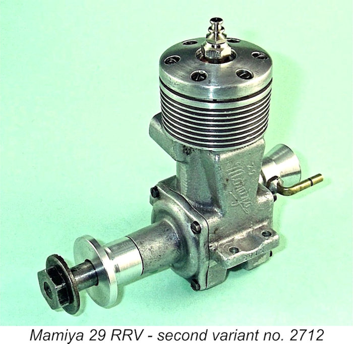 A review of the above comments will confirm that the main functional departures from the FVR model which are apparent in the RRV design were the single ball race shaft, the use of disc valve induction (which gives far more rapid opening and closing and also offers a more direct pathway for the incoming gas), the use of a ringed alloy piston (which is unquestionably lighter than its lapped cast iron counterpart), a slightly longer transfer period, a slightly lower compression ratio and a somewhat more open venturi throat (7.5 mm diameter with a 3.5 mm spraybar and no restrictor).
 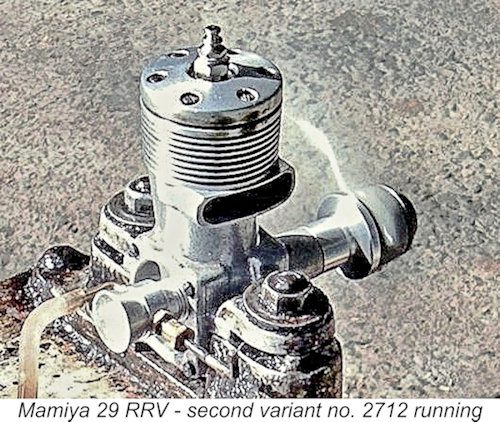 The cylinder head too was different in that it had a higher profile and a polished finish which was apparently produced by brushing. It appeared in fact to be identical to that used concurrently on the FRV models. The additional thickness meant that a long-reach plug was now called for. The needle valve assembly too was identical to that used on the FRV models, indicating a clear intention to maximize the commonality of parts between the “production” RRV and FRV versions.
 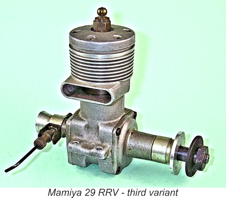 What appears to be the final version of the Mamiya 29 RRV was specifically described by the Japanese previous owner of my example as a “Type C”, which clearly implies the existence of Type A and Type B models. At present, I don’t know whether Types A and B were the two known earlier variants of the Mamiya 29 RRV described previously or whether they were simply other models in the contemporary Mamiya range. The former possibility appears to me to be by far the more likely. I also don’t know whether or not these “Type” designations were applied by the factory or whether they are simply used by Japanese collectors to distinguish between the various RRV models. If anyone out there can clarify this, I’d be most grateful!!
 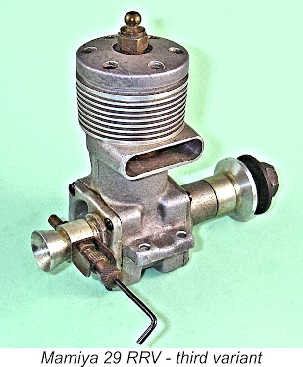 The result of this change was an increase in the total exhaust opening period from 120 degrees to 130 degrees (65 degrees either side of bottom dead centre), with a parallel increase in the transfer period from 110 degrees to 120 degrees (60 degrees either side of bottom dead centre). The change also eliminated the sub-piston induction which had been a feature of the previous variant.
 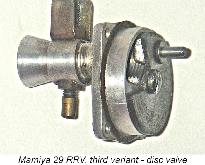 The use of a steel rotor is an unusual approach, but it has much to commend it. At the time in question, light alloy was still widely used in disc valve engines despite having shown itself to be a less-than-optimal material for this component. A steel rotor running against an alloy backplate should lap itself in use to a perfect sealing finish which should easily outlast the rest of the engine. Indeed, a number of previous model engine designs had used this approach successfully, and others were to do so later.
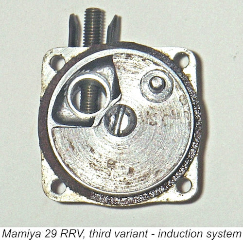
 The crankcase of this model continued to be a gravity die-cast item, as did the other castings employed apart from the cylinder head, which evidently continued to be based upon the same die-casting used for the companion FRV model. No components of the engine were painted or otherwise coloured, presumably as a cost-cutting measure. The painting process had also been eliminated on the companion final model of the FRV version, as noted earlier.
 | |