
|
|
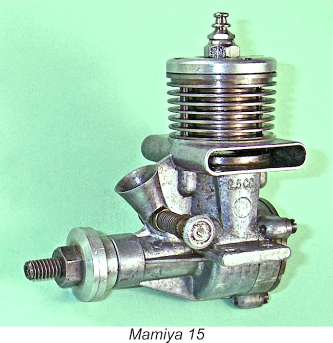
The Mamiya 15
In a separate article to be found elsewhere on this website, I’ve recounted the start-to-finish history of the Mamiya model engine venture. Readers wishing to learn the full story of this range are referred to that article – I have no intention of repeating the bulk of that material here. My present focus will be restricted to the 2.5 cc Mamiya 15 glow-plug motor, with a brief reference to its vanishingly-rare diesel offshoot.
The Mamiya 15 appears to have been produced in response to the 1954 introduction of the Fuji 15, which was described by Peter Chinn in his 1954/55 glow engine summary (“Model Aircraft”, May 1955) as Japan’s first commercially-produced model engine built to the new international displacement The Mamiya 15 seems to have appeared not that long after the Fuji 15, almost certainly later in the year 1954. It was thus the second Japanese model engine to be built to the FAI’s new international displacement limit. It was most probably introduced more or less concurrently with the very similarly-designed .099 cuin. Mamiya 9X model described in my separate article on the Mamiya .099 cuin. models to be found elsewhere on this website.
Interestingly enough, there was no mention whatsoever of the Mamiya range in Peter Chinn’s aforementioned 1954/55 "Model Aircraft" summary despite the well-established fact that the range had been in production for at least 6 years as of 1954! The contemporary Haru range, which dated from 1945 and also remained in production as of 1954, was omitted as well. It appears that Chinn was still getting up to speed on Japanese products as of late 1954 when this summary was most probably compiled. At that point O.S., Enya, Fuji, KO, ROC and Hope were evidently the only then-current Japanese model engine ranges which had come to his attention.
However, it’s clear that the likes of Mamiya, KO and Fuji were quite content to leave Enya and O.S. squabbling about bragging rights through competition success! In the minds of companies like these, the formula for marketplace success was the production of low-cost engines of reasonable quality, good durability, easy handling and acceptable “sports” performance, since potential customers for such engines always far outnumbered those seeking the latest and hottest engines regardless of cost. Fuji made no attempt to upgrade their 15 model to compete in performance terms with O.S. and Enya. The Mamiya 15 to be described below adhered to a similar design philosophy. I’m able to present some pretty solid information on this engine because I’m fortunate enough to own a fine example which was acquired from the collection of my late and much-missed friend and colleague Jim Dunkin. In addition, the engine was described in some detail in the “Motor Mart” feature of the June 1955 issue of “Aeromodeller” magazine. The Mamiya 15 – Description
The engine was built up around a rather intricate main pressure die-casting which incorporated the crankcase, twin exhaust stacks, twin bypass passages, main bearing and intake venturi as a single unit. This of course required the use of a removable backplate which was secured in place by three screws. No provision was made for a tank to be mounted on this backplate. All castings were very cleanly executed. The unhardened steel cylinder featured integrally-formed cooling fins. The turned alloy cylinder head was secured by four screws, two of which extended down through holes in the integral cooling fins to locate in tapped bosses fore and aft on the main casting. The radial orientation of the cylinder in the crankcase was thus secured. The head was lapped into the top of the cylinder, no gasket being used.
The Mamiya 15 featured a novel form of reverse-flow scavenging featuring sawn exhaust and transfer ports. At the time in question, such a scavenging system frequently took the form of an arrangement of 3 or 4 pairs of stacked exhaust and transfer ports distributed radially around the cylinder’s perimeter. The bypass passage which fed the 3 or 4 sawn transfer ports generally consisted of the annular space between the lower outer cylinder wall and the inner wall of the upper crankcase. The idea was that the function of the ports would be relatively unaffected by the precise radial position of the ports in the case, thus allowing the use of a screw-in cylinder if desired. Engines such as the A-M 25, D-C diesels, M.E. models and E.D. Racer typify this arrangement. Unfortunately, this configuration inevitably restricted the available bypass area. To get around this limitation, the Mamiya designer elected to employ a significantly modified form of reverse flow scavenging using sawn ports. To begin with, advantage was taken of the fact that the radial orientation of the cylinder in the crankcase was fixed by the previously-mentioned use of machine screws to hold it in place. There were now only two exhaust ports and two transfer ports, all of which were positioned securely in pairs on opposite sides.
It will be seen that the cylinder featured a thick diametric expansion immediately below the exhaust ports, This expansion served as the cylinder location flange. A primary function of this unusually thick flange was clearly to guard against distortion of the cylinder when the two cylinder hold-down screws were fully tightened. The expansion rested on a wide shelf formed in the upper crankcase casting, being sealed with a thick fibre gasket. This shelf is clearly visible in the accompanying image, as is the left-hand bypass passage. Two very wide and comparatively deep opposed rectangular exhaust ports were cut though the cylinder wall immediately above this expansion on opposite sides. These ports discharged into twin stacks placed one on each side of the upper crankcase casting. This twin-stack configuration was then very much in vogue in Japan, with designs by O.S., KO and Fuji also using this arrangement at the time.
The designer got around this in a very ingenious and (in my experience) unique manner by locating the top of the transfer ports in their usual position immediately below the lower lip of the exhaust ports but creating the transfers by milling away two crescent-shaped segments of the inner surface of the cylinder location flange where it formed part of the cylinder bore. The vertical height of the milled ports was such that the lower portion of the port broke through the cylinder wall immediately below the flange (visible in the above image), while the balance of the milling took place within the flange itself. This resulted in the removal of crescent-shaped segments of the lower surface of the flange on both sides. The resulting crescent-shaped cavities lay open both to the bypass passages in the crankcase and to the transfer port itself. The result was an opposing pair of crescent-shaped cavities within the cylinder location flange which were open to the bypass passages on their lower faces outside the lower cylinder wall and communicated directly with the cylinder bore along their entire inner edges where they intersected the bore. This approach allowed the use of a flange which was sufficiently thick to resist distortion while at the same time minimizing the unavoidable delay between the opening of the exhaust and transfer ports respectively. Ingenious …………… It should be obvious that the transfer ports must have been milled from the inside of the bore to accomplish this, since the unbroken integrity of the cylinder location flange’s outer perimeter had to be preserved to maintain a crankcase seal. The same tool seems to have been used to create both the exhaust and transfer ports, probably at the same setting, since their vertical heights are identical. This required a challenging machining set-up requiring a high level of precision! The two transfer ports were fed by two integrally-cast bypass passages of generous dimensions, one on each side of the main casting.
However, the arrangement did impose the usual sawn-port limitation of a relatively long blow-down period and a somewhat restricted transfer period, since no overlap could be provided between the exhaust and transfer ports. In this respect, it represented a step backwards from the earlier cross-flow loop-scavenged designs manufactured by Tokyo Hobbycrafts, which had featured a considerable degree of port overlap. The crown of the turned cast iron piston had a relatively steep-sided conical profile with a central flat area. The con-rod big end was bronze-bushed, while the 8 mm diameter crankshaft also ran in a bronze bushing. It featured a large straight-sided induction port which produced rapid opening and closing of the induction system – I haven’t taken my well-settled example apart to examine its precise shape or method of production. The needle valve was a stubby affair with a knurled brass control disc at its outer end. So much for the engine’s highly individualistic design features – how did all of this ingenuity translate into performance terms? Let’s find out! The Mamiya 15 on Test
Warring noted specifically that this engine was not commercially available in Britain, so presumably it was included mainly as a “curiosity” and an interesting insight into the then-arcane world of Japanese model engines. It must be remembered that since few British modellers had ever so much as seen a Japanese engine at this time, there was a certain Oriental mystique and a great deal of misconception regarding engines from that country. Ron Draper’s O.S. Max-powered victory at the free-fight World Championships later in 1956 was to change this perspective forever, but that event still lay in the future when this test was published. Warring was unstinting in his praise of the Mamiya .15’s overall quality, stating that it was “characterized by first-class design and workmanship throughout” and that it was “better than the average American glow motor as regards crankshaft bearing fit and good compression”. It is difficult for us to realize today that at the time in question these comments would have come as a great surprise to most British modellers, who still tended to subscribe to the prevailing elitist contemporary view of Japanese products as being at the lower end of the quality scale. Warring singled out the quality of the rather intricate crankcase die-casting as being particularly worthy of comment. He was also quite impressed with the engine’s unusual transfer porting arrangement, characterizing this as “particularly clever”. However, he quite legitimately criticized the nearness of the rather “fiddly” needle valve to the propeller disc, also stating his view that the mounting lugs could have been made somewhat stronger. One of the lugs on his test example was apparently cracked. An oddity in Warring's test report was his statement that the cylinder assembly screws were 7BA items, while the prop mounting thread was 1BA! Very odd for a Japanese motor of this vintage! All I can say is that my example uses M2.5x0.45 cylinder assembly screws, while the prop mounting thread is M5x0.8. Admittedly, these are very close to the BA equivalents cited by Warring - perhaps his measuring was in error.
Warring noted that the engine cost the equivalent of 40 shillings on the Asian market as of early 1956, re-confirming the manufacturing cost advantage still enjoyed by Japanese producers at that time. There was clearly no way that any contemporary British manufacturer could possibly compete in the same market at these prices, especially with a product of the kind of quality apparent in the Mamiya 15. It is figures like this that explain the failure of British model engine manufacturers to make any real headway in the Asian market.
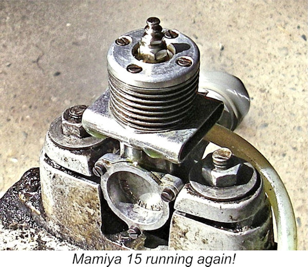
Warring summarized the engine rather politically-incorrectly (by today’s standards) as “a neat “Nip”” which would be “fine for sports flying or ‘open’ contest work”. The engine never appears to have made it outside of Japan in significant numbers, the consequence being that examples are relatively rare today outside their country of origin. The Mamiya 15 Re-Appraised I’ve commented previously that the performance figures recorded by Ron Warring in his various engine test reports generally tended to be a bit on the low side when compared with figures obtained by Peter Chinn of “Model Aircraft” for the same engine. Indeed, my own latter-day test figures tend to surpass those reported by Warring. I have no ready explanation for this – it must be down to differences in testing procedures and engine management. Regardless, there would obviously be value in running my own test of this engine since I had a fine example ready to hand. Speaking objectively on the basis of decades of experience, the engine's design features would lead one to expect a somewhat higher performance than that measured by Warring. However, this is an impression that clearly warrants testing. My example has undoubtedly been mounted and used, but it remains in fine original condition, hence constituting a fully representative test subject. I decided to try the engine on my standard set of 6 test props which I generally use for 2.5 cc non-racing glow-plug motors. The test fuel was a castor-based 15% nitro brew as recommended by the manufacturers. In view of the unusually low compression ratio, an Enya no. 3 (hot) glow-plug was used for this test. A couple of legitimate criticisms of the Mamiya 15 presented themselves immediately. Firstly, I can fully endorse Warring’s comment that the needle valve control is way too close to the prop disc for operator safety, also being very difficult to manipulate due to its unusually short lateral projection from the intake. And secondly, the length of the threaded prop mounting spigot at the front of the shaft is far too short – an 8x6 APC prop could not be fitted I began this test with an APC 8x4 prop fitted, intending to give the engine a little preliminary shake-down running prior to the commencement of the actual test. I'll begin my report by saying that I found absolutely no support for Ron Warring's comment that the Mamiya 15's starting was "not all that brilliant". It wasn't necessarily a consistent first-flick starter, but two or three flicks following an exhaust prime invariably had it going. In way could it be classified as being in the least bit difficult. Why Warring felt the need to resort to an electric starter "to ensure positive results" is quite beyond me! Once running, the plug could be disconnected immediately with little loss of speed, indicating that the compression ratio was at least operationally adequate. The engine's needle valve response was found to be quite positive without being unduly sensitive. As a result, the Mamiya proved to be easy to set, with the proviso that one had to be very careful indeed when manipulating that rather fiddly needle valve. The risk of skinned knuckles was high, while the proximity of the very hot exhaust restricted one's access further. A longer needle valve control would have been appreciated. I put about ten minutes of rich running on the engine to settle it down, and then ran a series of test props. The results are recorded below.
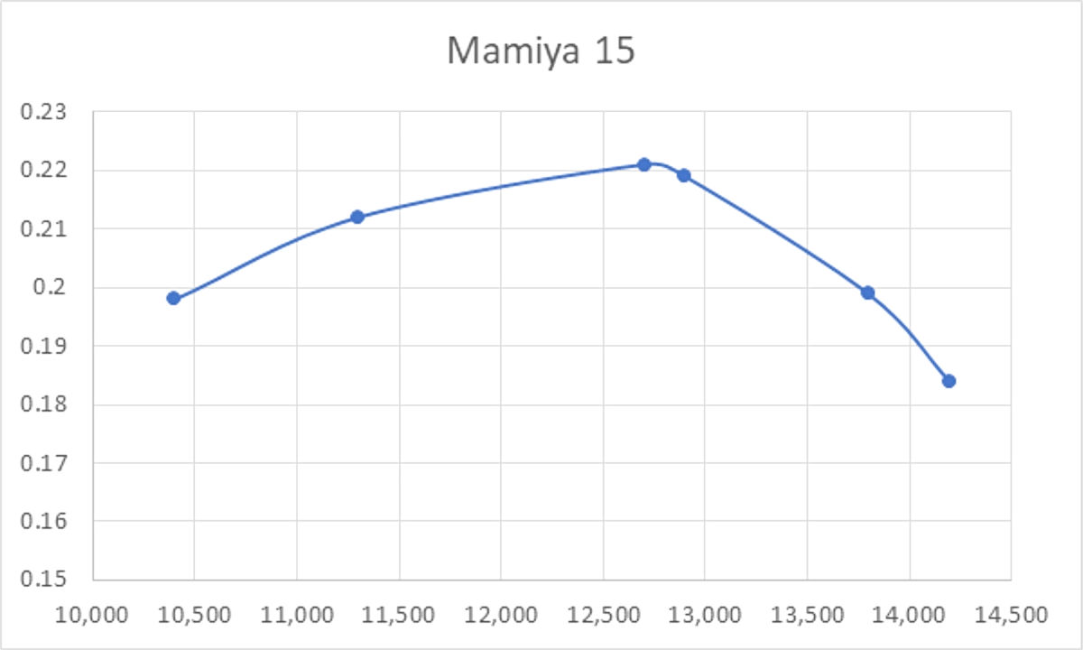
The engine wasn't too happy on the 8x6 prop, running a little erratically, but running smoothed out very nicely above 11,000 RPM, exactly as reported by Warring. Vibration levels were minimal throughout. The engine maintained its record of very prompt starts all along. However, above 13,000 RPM torque development seemed to fall over a cliff - the engine didn't appear to be at all keen on running much past 14,000 RPM. Running remained extremely smooth, but my impression was that the engine had run past its optimum speed in relation to the ignition timing established by the rather low compression ratio.
On its "hot" Enya plug, my example appeared to deliver around 0.221 BHP @ 12,700 RPM on 15% nitro. On Warring's 22% nitro, it would clearly do even better. An increase in the compression ratio to 8 or 9 to 1, thus advancing the ignition timing, would almost certainly extend the engine's useful speed range in an upward direction. A parallel change made by the factory to the companion .099 cuin. Mamiya 9X resulted in a very marked improvement in the performance of that model. Not an earth-shaking performance even by 1954 standards, but a pretty good showing for a sport-flying 2.5 cc glow-plug engine of that vintage weighing only 107 gm (3.77 ounces). For comparison, I note that Peter Chinn could only extract 0.22 BHP @ 12,750 RPM from the 113 gm (4.0 ounce) A-M 25 Mk. I tested in June 1955. The performances of the Mamiya 15 and A-M 25 Mk. I were essentially identical, with the Mamiya enjoying an edge in the power-to-weight department. Coupled with its excellent quality and fine handling, the Mamiya 15 would have made a very useful sports powerplant having the potential to deliver a long service life. The 8x5 would appear to be an ideal flight prop. The Mamiya 15 Diesel Model
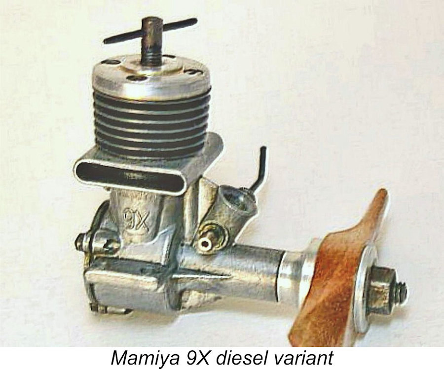
These engines are more or less in the “unobtanium” class today - even my Japanese informants have very seldom encountered examples, although they have access to photographs and references in the contemporary Japanese modelling media. It appears that very few were made and that few if any of those that were manufactured ever made it out of Japan. Although I don’t have examples of either of the two Mamiya diesel models, I’m fortunate in being able to share an image of the smaller Mamiya 9X version. It may safely be assumed that the larger 15 diesel model looked essentially identical. Conclusion It appears that the Mamiya 15 and its smaller companion 9X may well have been the last models to remain on offer from Tokyo Hobbycrafts. In a retrospective look at the Mamiya 60 which formed the subject of Peter Chinn’s “Foreign News” feature in the May 1979 issue of “Model Airplane News”, Chinn stated that the only Mamiya models listed for 1957 were those two models. Thereafter, nothing more was heard of the Mamiya range, implying that 1957 was the final year of production, both for the Mamiya 15 and the Mamiya range as a whole. A pity - this was a quality range whose manufacturers deserved a better fate. __________________________ Article © Adrian C. Duncan, Coquitlam, British Columbia, Canada First published February 2026 |
||
 In this relatively short article (by my standards!), I’ll present a review and test of one of the less commonly-encountered 2.5 cc glow-plug engines of the 1950’s – the Mamiya 15. This refreshingly out-of-the-rut design was manufactured by a company called Tokyo Hobbycrafts, which produced high-quality model engines under the Mamiya trade-name for ten years between 1947 and 1957.
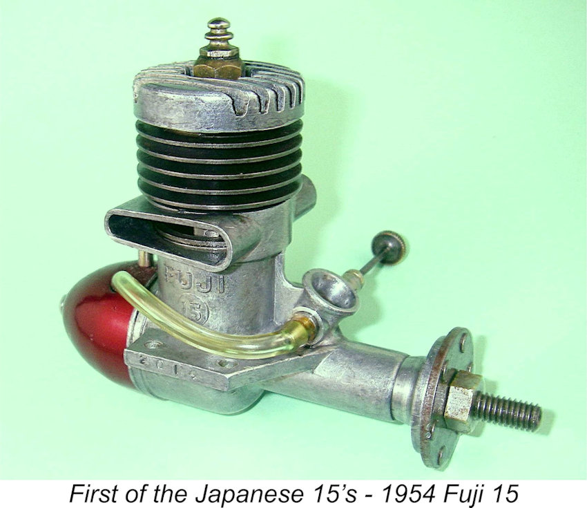 The first Japanese-made 2.5 cc (.15 cuin.) glow-plug engine to appear was the twin-stack Fuji 15 of 1954. The development of this unit was likely triggered by the FAI’s announcement that from 1955 onwards, FAI-sanctioned international power model competitions (other than control-line stunt and R/C) would be restricted to engines of 2.5 cc displacement.
 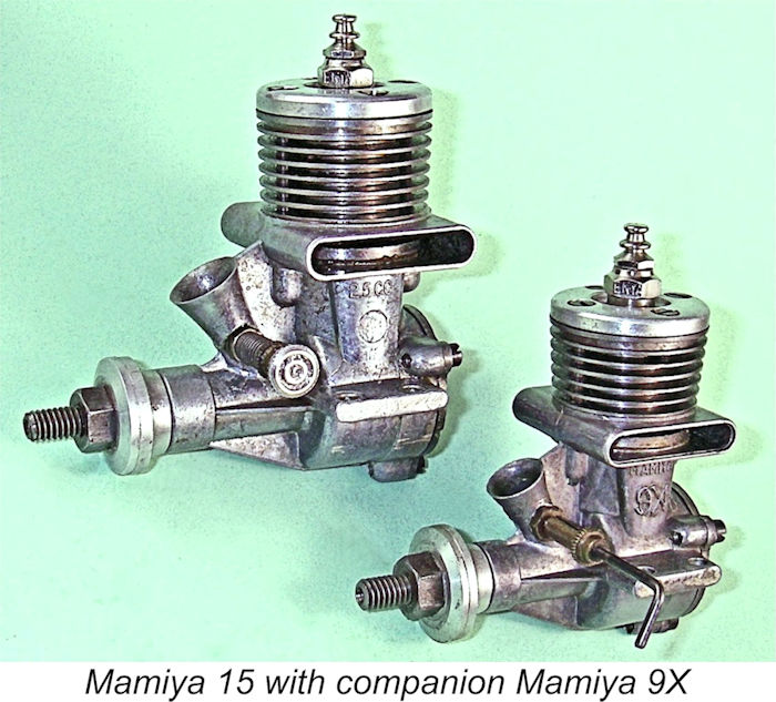 standard of 2.5 cc. Prior to this trend-setting move by Fuji, all Japanese engines had been produced to the prevailing American class displacement limits, which were of course delineated in cubic inches rather than cubic centimetres.
 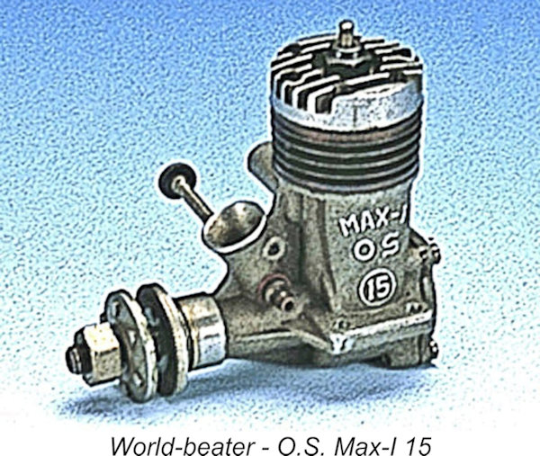 Others were quick to follow suit - O.S. introduced their fine Max-I 15 model in early 1955 and Enya were as usual very quick to respond to this move from their Japanese arch-rivals by introducing their own excellent 15-I model a little later in 1955.
 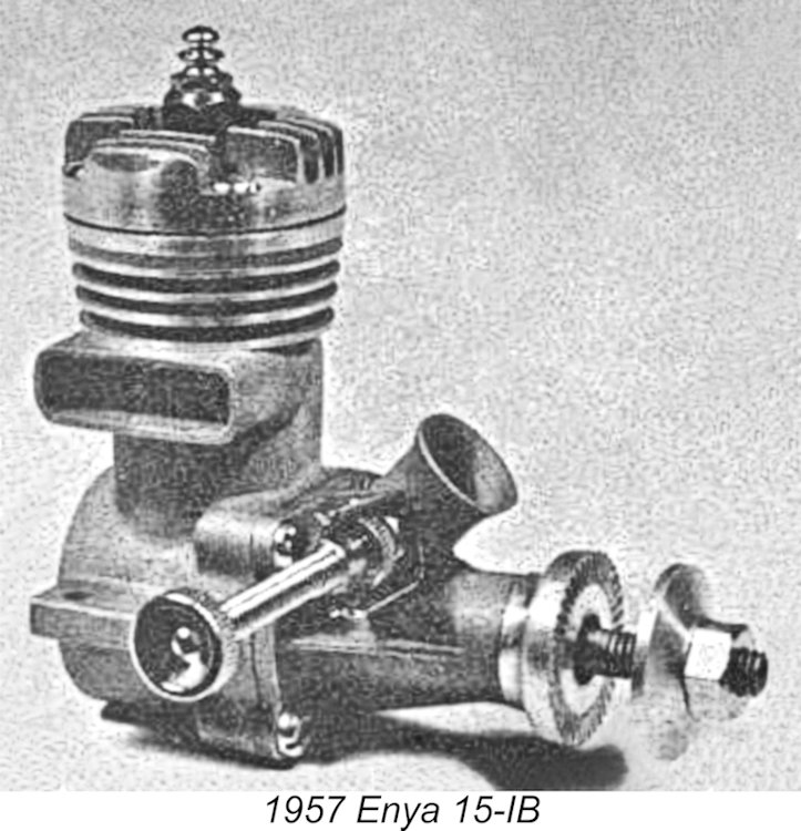 It is a testament to the rapidly growing capabilities of the Japanese model engine manufacturing industry that the O.S. Max-1 15 powered Britain’s Ron Draper to the 1956 free flight World Championship less than two years after the introduction of Japan’s first model engine meeting the FAI’s international displacement standard. Quite a statement of Japanese technological capabilities!! Enya responded immediately with their revised 15-IB model, and the battle for technical and sales supremacy between Enya and O.S was to rage on for many years.
 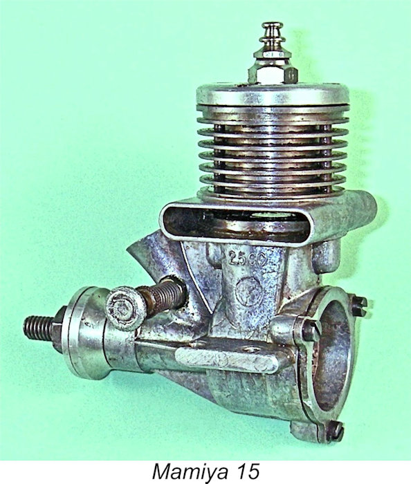 Beginning with the tale of the tape, nominal bore and stroke of the Mamiya 15 were a slightly over-square 14.7 mm and 14.4 mm respectively for a nominal displacement of 2.44 cc. Checked weight was a commendably light 107 gm (3.77 ounces). The latter figure is illuminating because it reflects the fact that the Mamiya 15 was actually very little heavier or bulkier than the average contemporary British 1.5 cc diesel while producing as much power as any of those units, or even more. Accordingly, one could readily use this engine in a typical British 1.5 cc design to obtain a very lively flight performance indeed!
 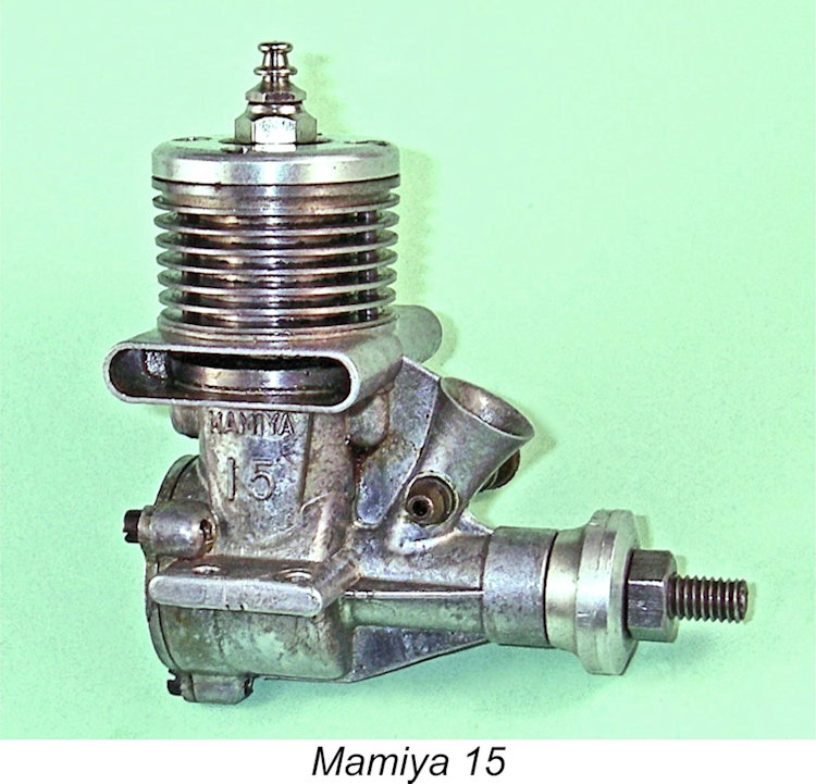 Measured compression ratio
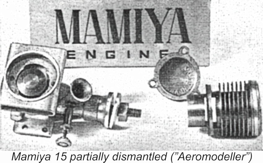 Fortuitously enough from my perspective, the previously-cited “Motor Mart” article of June 1955 included an image of a partially-dismantled example of the Mamiya 15. Since this image does much to clarify the following description, it is reproduced here. The "Mamiya Engine" characters at the rear in the image are on one side of the engine's box.
 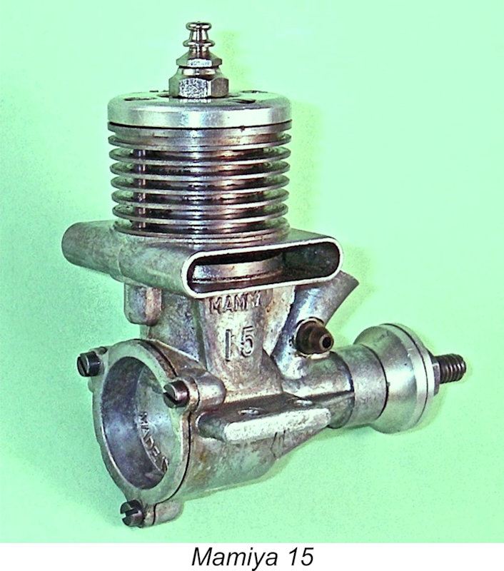 Twin opposed transfer slots were milled through the cylinder walls directly beneath the twin exhaust ports. The considerable thickness of the cylinder location flange below the exhaust ports created an interesting challenge for the designer when it came to forming the transfer ports. The thickness of the flange was such that the ideal location for those ports immediately below the exhaust ports was almost fully occupied by the flange itself. The thickness of the flange also meant that cutting the transfer ports in the usual way below the flange would have resulted in an unacceptably long delay between the opening of the exhaust and transfer ports respectively. Hmmmm ……… what to do?!?
 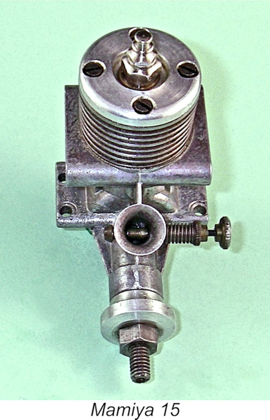 This design approach had the benefit of placing the bypass and transfer ports at the sides where gas access from the crankcase to the twin bypass passages was at its least restricted. It also provided for the provision of a far larger total bypass area than would have been possible with conventional radial porting. In addition, it preserved solid unbroken sections of expanded cylinder wall directly beneath the hold-down bolts fore and aft, thus once more minimizing the possibility of cylinder distortion.
 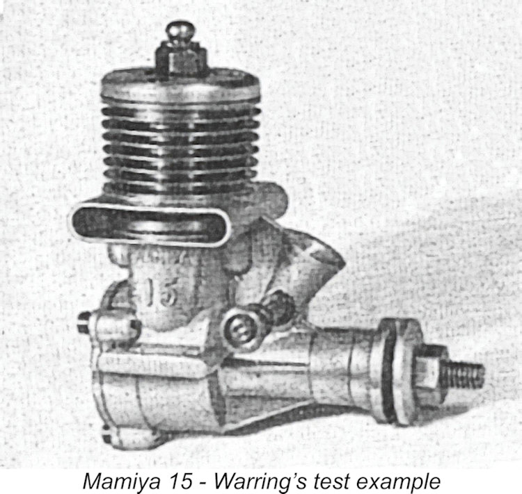 The Mamiya 15 was the subject of a
 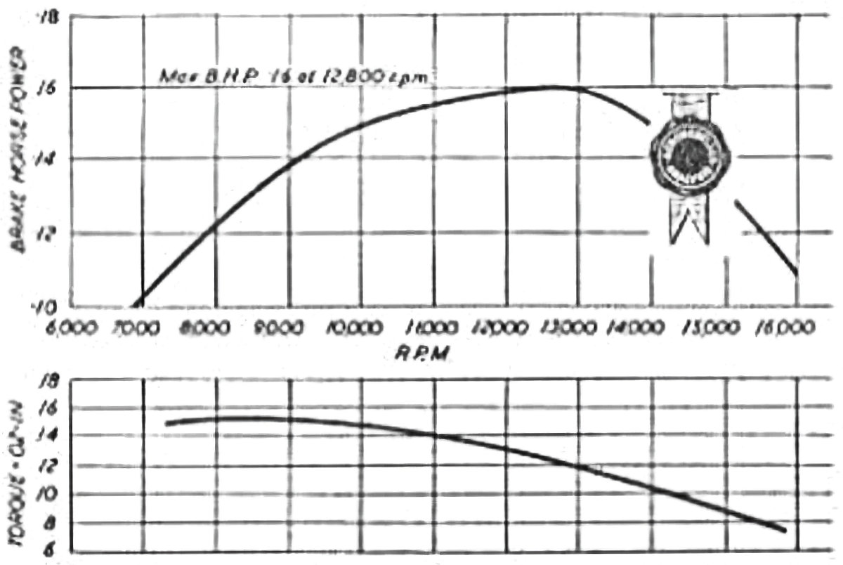 In terms of the engine’s handling, Warring commented that starting was “not all that brilliant”, although he did not qualify this frustratingly general statement. He admitted to using an electric starter for most of his testing "to ensure positive results". Nor did the engine impress all that much in performance terms - Warring only extracted 0.16 BHP at 12,800 RPM on 22% nitro fuel, well down on most contemporary British 2.5 cc plain-bearing diesels, although at least on par with the best of the British 1.5 cc diesels of comparable weight and bulk. The test report included the general statement that the Mamiya 15 was “loud in exhaust” while being “fair in power output”. Warring found that the engine was “much happier running at speeds of 11,000 RPM and above than at lower speeds”.
 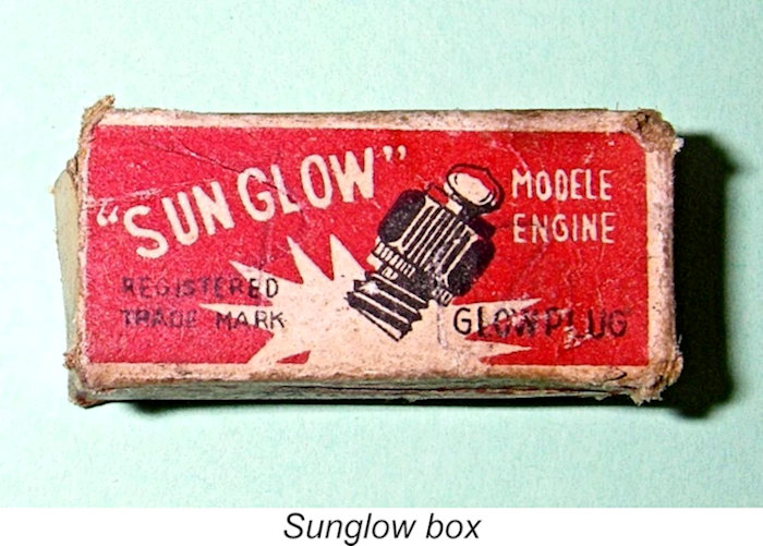 As received, Warring’s test engine was fitted with a Japanese “Sunglow” plug. These plugs were apparently in common use in their country of origin - I have several early Japanese glow-plug motors fitted with them. They featured an unusually heavy element having a strange "brownish" colour which required a full 2 volts to create any kind of glow. In an amusing comment presumably from Warring which appeared in the previously-mentioned “Motor Mart” feature of the June 1955 issue of “Aeromodeller”, the illumination created by the application of even a full 2 volts could reportedly “only be likened to an eclipse!” A K.L.G. plug was used for Warring’s testing, although he admitted that performance with the Sunglow plug was identical once the engine was running.
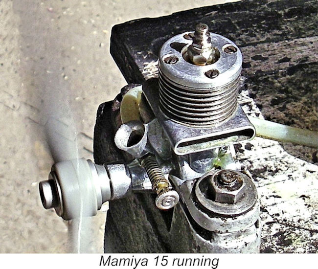
 Like the companion 0.099 cuin.
 | |