
|
|
The Mamiya .099 Series
We saw in my overview article that as of 1948 the manufacturers of the Mamiya model engine range, Tokyo Hobbycrafts, had made an impressive debut in the highly competitive field in which they were participants with their outstanding .60 cuin. sparkie. They were now poised to expand into the “popular” displacement categories for which mass sales might reasonably be expected. Here I’ll focus my attention on the succession of engines which were to prove to be perhaps the most popular and enduring Mamiya models - the .099 cuin. series of glow-plug motors.
Moreover, the “intimidation” factor was relatively low - always a key issue for complete beginners. Finally, Japanese labour costs allowed .099 engines to be produced and sold domestically at prices which matched or even beat those of the American ½A models in their home market.
KO added their own twin-stack .099 glow-plug design to the list in late 1953, while the almost forgotten Boxer range also included a series of .099 models during this period. Enya was actually a Johnny-come-lately among Japanese manufacturers in this displacement category, waiting until May 1954 to launch their own initial .099 model, the excellent Enya 09 Model 3001. The manufacturers of the Hope range also released an .099 cuin. model at around the same time. Reviewing the above summary, it seems clear that entry into the .099 market quickly became viewed by most of the emerging post-war Japanese model engine manufacturers as a priority goal in the competition for mass sales, at least in the domestic market. By contrast, it’s very noticeable that almost all of the Japanese manufacturers completely ignored the .049 category during its heyday in the 1950’s. The sole exceptions were Fuji and the almost forgotten ROC and Haru companies. Of these, only Fuji produced .049 engines in any quantity. Let’s begin by taking a look at what seems to have been Mamiya’s first .09 model - the “Chochin” .099. The Mamiya “Chochin” .099
A somewhat surprising feature of the "Chochin" .099 model is the fact that it was an over-square design. Visually, the engine gives the impression of being a typical long-stroke model of its era, but actual measurements taken from my own example refute this notion. The engine features nominal bore and stroke measurements of 13 mm and 12 mm respectively for a true displacement of 1.59 cc (0.097 cuin.). Weight is a not-unreasonable 64 gm (2.26 ounces) as illustrated. There is no provision for the fitting of a tank. It’s an open possibility that the "Chochin" models may have appeared initially in spark ignition form - in the present absence of supporting evidence, I can’t be sure. The two straws in the wind are the presence of a machined boss at the front of the main bearing housing as well as The "Chochin" engines featured radial cylinder porting allied to tall cast iron cylinders with integral cooling fins and blind bores. In adopting these arrangements, the engines harked back to the early post-war products of the Japanese model engine industry, when makers such as Hope, Haru and TOP all used cylinders of a similar nature. Both models used FRV induction with a screw-in brass venturi - another typical early post-war Japanese design feature. Exhaust porting in the .099 model consisted of four sawn slots arranged in a radial pattern, with four narrow pillars of metal providing This system exhibited the inherent radial port shortcoming of necessitating a longer-than-optimal blow-down period due to the limitation that no overlap could be provided between the exhaust and transfer ports. The structural integrity of the upper cylinder also seems open to question – the four narrow cast iron pillars which separated the exhausts look as if a moderately hard crash could easily fracture them. The engine starts easily and runs very smoothly, albeit not developing any notable power output. It appears that neither of the "Chochin" models remained long on the market, which explains their present-day rarity. By late 1949 the company had developed far more up-to-date models in both the .09 and .29 cuin. displacement categories. Both of these revised products shared a very similar design configuration. We’ll look next at the drastically re-configured .099 cuin. series which followed the "Chochin" model just described. The Second-Generation Mamiya .099 FRV Models - General Overview
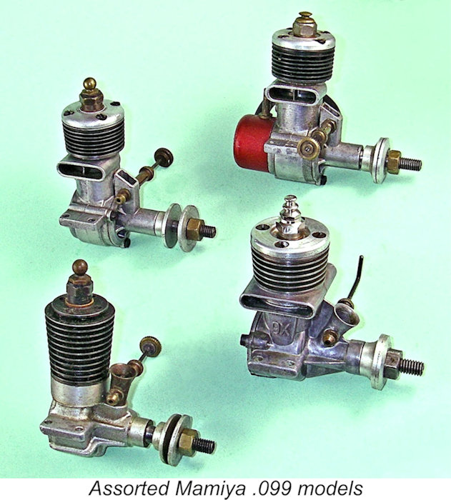
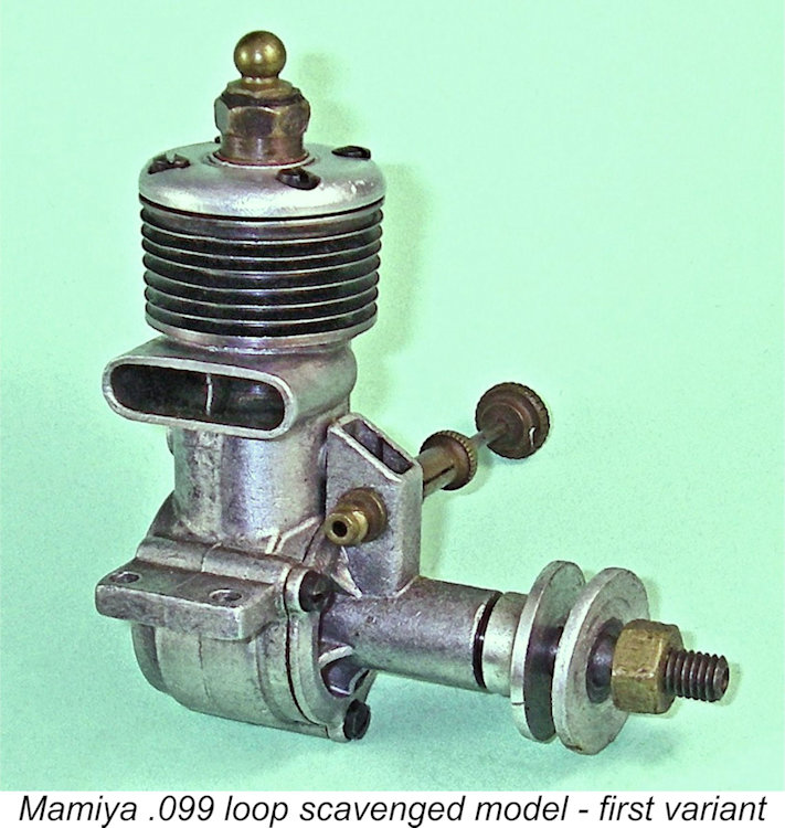
Like all of the Mamiya engines, examples of these attractive and well-made little motors are not particularly common today outside Japan, but examples do appear from time to time on eBay. Four variants of the loop-scavenged Mamiya .099 FRV model have been identified to date. All of these are based upon the same very simple loop-scavenged configuration which bore a strong “family” resemblance to the Mamiya 29 FRV series described elsewhere. Bore and stroke of the little Mamiya were both 12.7 mm for a nominal displacement of 1.61 cc (.098 cuin.). For their displacement, these variants were both unusually light and remarkably compact, weighing only around 2¼ ounces (64 gm) with tank. Without the tank, this weight was reduced to just over 2 ounces (57 gm). The loop-scavenged Mamiya .099 is an interesting design in a number of ways, displaying a healthy dose of Ohlsson & Rice influence. The steel cylinder was secured in the crankcase by two spot-welds fore and aft below the exhaust port level, just as in the O&R engines. These two welds were solely responsible for retaining the cylinder in all variants of this model. The light alloy cylinder head was retained by four short machine screws which engaged with tapped holes in the topmost cylinder flange. Another similarity to the Ohlsson range was the use of a backplate which was integral with the die-cast main crankcase. In addition, the shaft and rotary valve set-up were carried in a separate Ohlsson-style front housing secured to the case by three screws. The vertical intake located immediately in front of the main case and the recessed front face of the mounting plate for the main bearing housing were further Ohlsson look-alike features. Finally, the mounting lugs were set well above the centre line of the crankshaft, again just as in the Ohlsson range.
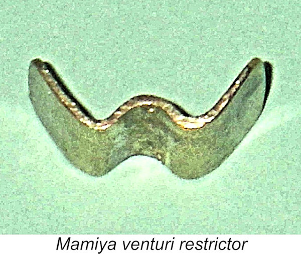
The extent to which Ohlsson influence is apparent in the Mamiya .099 suggests a relatively early introductory date for the design. It’s presently impossible to be certain, but a date around 1949 (certainly more or less contemporary with the very similar 29 FRV model described separately) appears to represent a reasonable guess. After that time, it would appear more likely that influences from some of the more progressive competing designs then appearing would have predominated. The steel cylinder was of the loop-scavenged pattern more commonly seen on larger-displacement glow-plug engines, with large opposed transfer and exhaust ports cut through the relatively thin cylinder wall. The transfer port overlapped the exhaust port to a significant The Mamiya .099 used an innovative type of intake restrictor consisting of a simple W-shaped “cookie cutter” item which was bent from brass sheet and retained in place by the spraybar, blocking the forward half of the intake when in position. The spraybar engaged with the reverse curve at the centre of the "W". This fitting was easily removable if more power was required and suction was not an issue. These components are missing from many examples, but a replacement is easily made. When running on suction, the engines generally perform in a far more stable and controllable manner with the restrictor fitted. As stated earlier, four distinct variants of the loop-scavenged Mamiya .099 FRV model have so far been identified. These are generally very similar, with the differences being relatively subtle. Let’s look at them in turn, describing them in the order in which the available evidence suggests that they were placed on the market ………….. Mamiya .099, First Version
Like those of the early variant of the companion 29 FRV model, the integral cooling fins are turned extremely thin, hence being quite vulnerable to damage through accident or careless handling. The company was soon to attend to this issue, just as they did with the larger model. Mamiya .099, Second Version
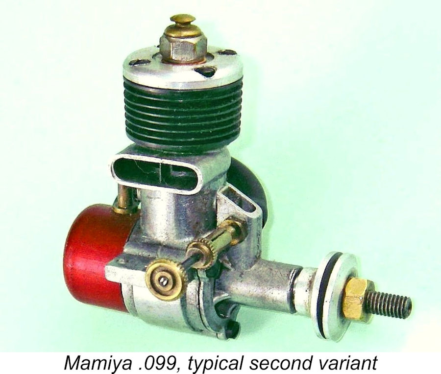
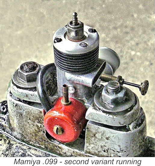
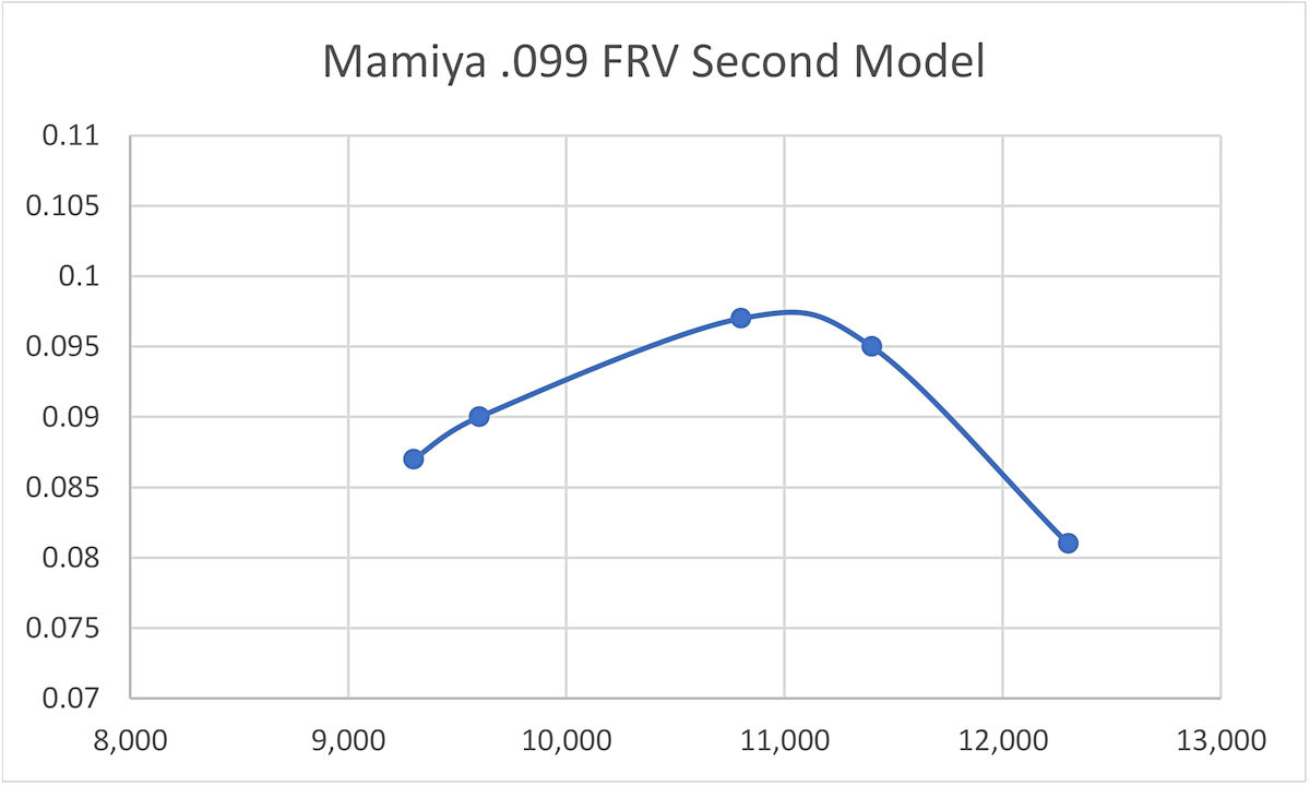
The most immediately obvious change is the addition of a neat red-anodized back tank very much like that used on the contemporary companion 29 model. The rim of this tank is machined to create a peripheral step for secure location of the tank against the backplate. The integral backplate is correspondingly machined to accurately and securely locate this tank with a good seal. The tank is retained in the usual way by a screw which engages with a drilled and tapped hole in the central boss cast into the backplate. An annoying feature of this tank, and one which was apparent on other Japanese engines such as the Hope and Fuji series, is the failure of the makers to include a pin-hole air vent for filling purposes. There is just a single spigot plus the hole for the fuel The integral cylinder cooling fins are turned substantially thicker than they were on the earlier model and the cooling grooves between the fins are correspondingly narrower. The actual height of the cylinder remains unaltered. This step was presumably taken to provide greater resistance to accidental damage. The cylinder head too is different on this model. For one thing, the radius at the upper edge is far smaller, giving the head a more “squared-off” look. For another, the slightly raised boss for the glow-plug has been transmuted into a shallow The illustrated example of this engine has clearly been mounted and put to a limited amount of use, but it remains in excellent and completely original condition, including its tank and "cookie cutter" intake restrictor. I undertook a bench test of this engine using a fuel containing 15% nitromethane and a "hot" Fox glow-plug. This test revealed that the little Mamiya was an almost instantaneous starter following a port prime. It also ran very smoothly, with minimal vibration and excellent needle response. Optimum settings were easily established for each prop tested, with no tendency to sag on a maximum lean setting. The needle held its settings perfectly at all speeds. The following data were recorded:
The Mamiya .099 FRV seems to have developed a peak output of around 0.098 BHP @ 11,000 RPM. By 1951 standards, this is a useful enough performance for a lightweight 1.61 cc glow-plug motor, although it falls somewhat short of matching competing models such as the contemporary McCoy "9" from America. Even so, it would have proved to be a completely satisfactory powerplant for use in the smaller non-competition power models of that era. Both 7x6 and 7x5 props would appear to be ideal choices depending on the application. Mamiya .099, Third Version
This version of the Mamiya .099 appeared along with an example of the previous (second) version in a short article entitled “Motors from Japan” which was published in the January 1953 issue of “Aeromodeller” magazine but was clearly written in late 1952 to meet the editorial deadline. This article was based on information regarding then-current Japanese products which had been provided to the magazine by a returning Royal Navy officer, Lieutenant D. A. McNaughton. This officer had just completed a period of active service in Korean waters (the Korean War was the hot conflict of the day).
The main value of this article to us in the context of the present review is the incontrovertible proof that it provides that the third version of the Mamiya .099 (with tank, modified fins, re-configured head and anodized wrap-around prop driver) was undoubtedly in existence as of the latter part of 1952. The clear presumption is that the versions described earlier had been introduced over the previous few years. However, the fact that both the second and third versions appeared together in this article suggests either that the change had only just occurred or that both versions were offered concurrently. It's certainly apparent that price was very much in favour of the Japanese manufacturers at this time, doubtless reflecting the far lower labour costs then in effect in Japan as well as the prevailing fixed exchange rate of ¥360 to the US dollar. The Mamiya had reportedly cost Lieutenant McNaughton the equivalent of 22 shillings (£1.10), and even the far larger O.S. 29 twin-stack model had been acquired for the equivalent of only 28 shillings (£1.40)!
Returning to the quoted “Aeromodeller” article, that review actually represents something of a watershed in terms of attention being paid to Japanese engines in the English-language modelling media. This was reportedly the first opportunity that the magazine staff had had to examine Japanese engines at first hand, and it’s clear that they were rather impressed, somewhat to their Mamiya .099, Fourth Version The final variant of the Mamiya .099 FRV of which I’m currently aware was generally similar to the third model just described apart from the cylinder head. The latter component was now provided with cooling fins which were milled into its upper surface. In all other respects, this model was externally identical to its predecessor, although there may have been internal changes of which I'm currently unaware. A Rare Bird - the Mamiya .099 RV
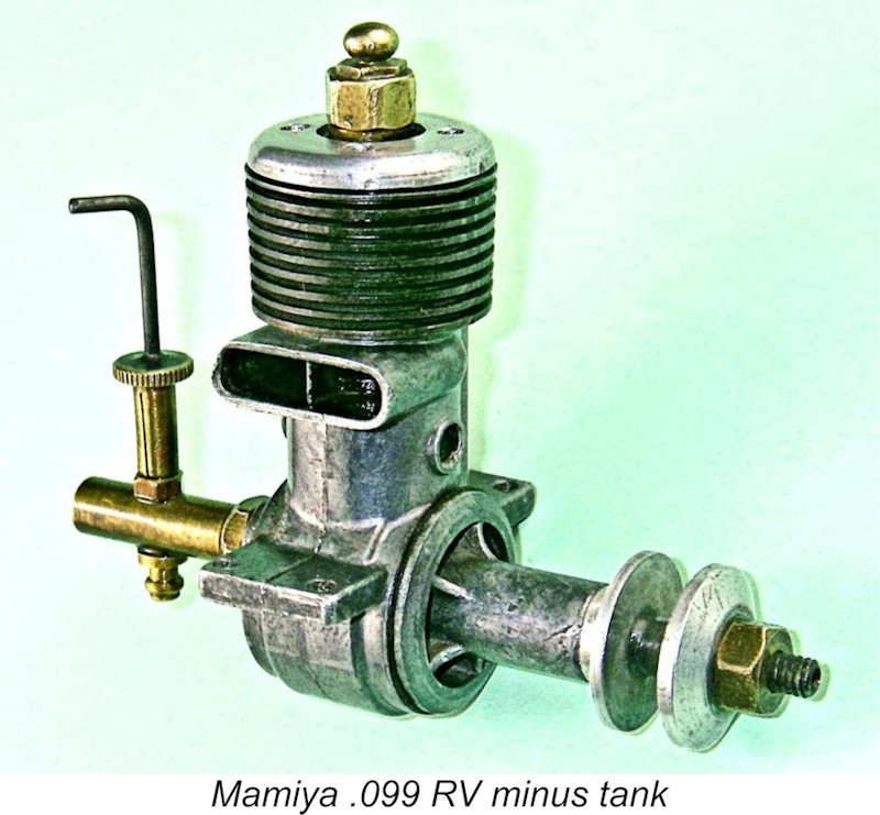
Bore and stroke of the RV version of the engine remained unchanged. However, both the main crankcase and front housing castings were completely revised. The front housing was not simply a modification of the FRV housing to eliminate the intake - it lacked both the FRV intake structure and the three lugs used to retain the FRV front cover The main casting was generally similar to that of the FRV model but lacked the now-redundant lugs for the front cover retaining screws, also including an integrally-cast quadrant on the upper exhaust side of the rear backplate face into which the brass intake tube threaded. A locknut was used to secure the intake in any desired orientation. The cylinder was more or less identically ported to that of the FRV version but was somewhat taller than that of the FRV model. This was made necessary by the fact that this variant used a screw-in cylinder head as opposed to the four-screw assembly used on the FRV versions. The extra height was required to accommodate the internally-threaded pocket into which the head screwed. A gasket was again used to create a seal. As with the FRV model, the cylinder was secured in the case by a pair of spot welds fore and aft.
The disc valve was of bronze, a very suitable material for this service. The intake was of brass tubing with a parallel bore throughout. Throat diameter was 5 mm with a 3 mm spraybar. A standard Mamiya .099 split-thimble needle was employed. The engine came with a hang tank of very minimal capacity - enough for sport free-flight use perhaps, but no more. Most annoyingly, it was not provided with a pinhole air vent, making A further annoying feature of this tank was the fact that the tank bowl appears to have been swaged into the top so that the two components cannot be separated by fair means. Since the spraybar serves to attach the tank, it follows that the spraybar and fuel pickup have to be in place in the tank top before the tank itself is added. Hence the spraybar cannot be separated from the tank assembly once the bowl is added. It would thus be necessary to used a separate standard spraybar of the type used on the FRV models to employ an external fuel supply. I suspect that many owners would have followed this approach. For my own part, I elected to make a complete replica carburettor assembly without the tank for testing purposes. Since I haven't given myself the opportunity to assess this very rare engine's internal structural integrity, I've never risked subjecting it to the rigors of a full test. The best that I can do is to confirm that it starts and runs very well indeed. The Mamiya 9X
Like its 2.5 cc big brother, the Mamiya 9X is very seldom encountered today outside Japan, quite possibly reflecting the fact that by the time these new models appeared, the Mamiya engines were already in the process of losing ground in their manufacturer's attempts to gain a share of the world market. Indeed, the range was destined to go out of production relatively soon. It would appear that comparatively few examples of the 9X found their way beyond Japanese shores. Both examples which I’ve been fortunate enough to acquire were purchased in Japan during the mid-1950’s and brought to the USA by returning American service personnel, from whom I acquired them years later.
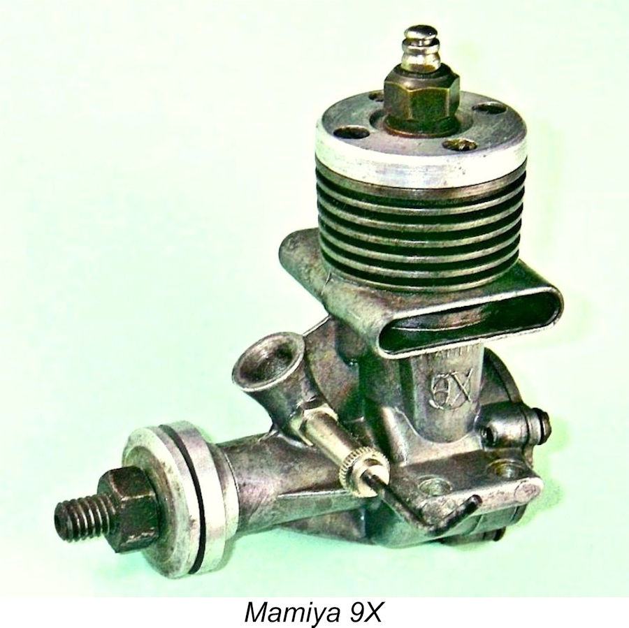
By now, the makers had recognized the practical limitations imposed upon the earlier .099 designs by the spot-welded cylinder used in those models. If a replacement piston/cylinder was required as a result of wear or damage, a new case had to be purchased as well. The same held true if a leak developed in the seal between the cylinder and crankcase or if the crankcase sustained damage. The revised model used a drop-in steel cylinder having integrally-formed cooling fins. This was secured to the crankcase by two of the four cylinder head hold-down screws. These two screws were far longer than the other two, passing right through holes in the cooling fins to engage with tapped holes provided in a pair of bosses cast into the crankcase fore and aft. The turned alloy cylinder head was lapped into the top of the cylinder, no gasket being used. Measured compression ratio of my example of the original version of the Mamiya 9X is a seemingly rather marginal 6.5 to 1. The clear implication is that the engine would benefit greatly from the use of fuel having a significant nitro content. The Japanese-language instruction sheet which accompanied the engine reportedly recommended a fuel containing 15% nitro.
Overall, the new model was also significantly bulkier than its predecessor. Its mounting holes were drilled to make it interchangeable in the same model with the earlier version, indicating that the company hoped to entice some of their earlier customers into switching to the new design. But the added weight might well have damped some of the required enthusiasm for making such a switch, added to which the original 9X was actually little if any more powerful than its predecessor. In fact, it was noticeably inferior at the lower end of the RPM scale, although it did exhibit a slightly stronger top end, as we shall see in due course. The engine was built up around a rather intricate main pressure die-casting which incorporated the crankcase, twin stacks, bypass passages, main bearing and intake venturi as a single unit. This of course required the use of a removable backplate which was secured in place by three screws. No provision was made for a tank to be mounted on this backplate. All castings were very cleanly executed. Cylinder porting arrangements were completely revised. The Mamiya 9X featured a novel form of reverse-flow scavenging which represented a complete departure from the former loop scavenging arrangement. At the time in question, a reverse flow scavenging system commonly took the form of an arrangement of 3 or 4 sawn pairs of exhaust and transfer ports distributed radially around the cylinder’s perimeter. The bypass passage which fed the 3 or 4 transfer ports generally consisted of the annular space between the lower outer cylinder wall and the inner wall of the upper crankcase. The idea was that the function of the ports would be relatively unaffected by the radial position of the ports in the case, thus simplifying assembly while allowing the use of a screw-in cylinder if desired. Engines such as the A-M series, D-C diesels, M.E. models and the E.D. Racer all typify this arrangement. Unfortunately, this configuration inevitably restricted the available bypass area. To get around this limitation, the Mamiya designer elected to employ a significantly modified form of reverse flow scavenging. To begin with, the radial orientation of the cylinder in the crankcase was fixed by the use of the two long machine screws to hold it in place. There were now only two exhaust ports and two transfer ports, all of which were positioned securely on opposite sides.
It will be seen that the cylinder featured a thick diametric expansion located immediately below the exhaust ports. This expansion served as the cylinder location flange. A primary function of this unusually thick expansion was clearly to guard against distortion of the cylinder when the two cylinder hold-down screws were fully tightened. The expansion rested on a wide shelf formed in the upper crankcase casting, being sealed with a thick fibre gasket. Two very wide and comparatively deep opposed rectangular exhaust ports were cut though the cylinder wall immediately above this expansion on opposite sides. These ports discharged into twin stacks placed one on each side of the upper crankcase casting. This twin-stack configuration was then very much in vogue in Japan, with .099 designs by O.S., KO and Fuji also using this arrangement at the time. Twin opposed transfer slots were milled through the cylinder walls directly beneath the twin exhaust ports. The considerable thickness of the cylinder location flange below the exhaust ports created an interesting challenge for the designer when it came to forming the transfer ports. The thickness of the flange was such that the ideal location for those ports immediately below the exhaust ports was more or less fully occupied by the flange itself. The thickness of the flange also meant that cutting the transfer ports in the usual way below the flange would have resulted in an unacceptably long delay between the opening of the exhaust and transfer ports respectively. Hmmmm ……… what to do?!? The designer got around this in a very ingenious and (in my experience) unique manner by locating the top of the transfer ports in their usual position immediately below the lower lip of the exhaust ports but creating the transfers by milling away two crescent-shaped segments of the inner surface of the cylinder location flange where it formed part of the cylinder bore. The vertical height of the milled ports was such that the lower portion of the port broke through the cylinder wall immediately below the flange (visible in the above image), while the balance of the milling took place within the flange itself. This resulted in the removal of a crescent-shaped segment of the lower surface of the flange on each side. These two crescent-shaped cavities were contained inside the material of the flange itself immediately below the exhaust ports. They lay open to the twin bypass passages in the crankcase.
It should be obvious that the transfer ports must have been milled from the inside of the bore to accomplish this, since the unbroken integrity of the cylinder location flange’s outer perimeter had to be preserved to maintain a crankcase seal. The same tool seems to have been used to create both the exhaust and transfer ports, probably at the same setting, since their vertical heights are identical. This required a challenging machining set-up requiring a high level of precision! The transfer ports were fed by two integrally-cast bypass passages of generous dimensions, one on each side of the main casting. This design approach had the benefit of placing the bypass and transfer ports at the sides where gas access from the crankcase to the twin bypass passages was at its least restricted. It also facilitated the provision of a far larger bypass area than would have been possible with conventional radial porting. In addition, it preserved solid unbroken sections of expanded cylinder wall directly beneath the hold-down bolts fore and aft, thus once more minimizing the possibility of cylinder distortion. In his March 1956 test of the companion 15 model (see separate article on the 15 models), Ron Warring was understandably impressed by this design approach, calling it “particularly clever”. However, the arrangement did impose the usual sawn-port limitation of a relatively long blow-down period and a somewhat restricted transfer period, since no overlap could be provided between the exhaust and transfer ports. In this respect, it represented a step backwards from the earlier cross-flow loop-scavenged designs manufactured by the company, which had featured a considerable degree of port overlap. The piston baffle was naturally gone, with the crown of the turned cast iron piston having a relatively steep-sided conical profile with a central flat area. Both the main bearing and con-rod big end were bronze-bushed. The crankshaft featured a large straight-sided induction port which produced rapid opening and closing of the induction system – I haven’t taken my well-settled example apart to examine its precise shape. The needle valve assembly differed from that of the former model, being nickel-plated and using the “bent wire” type of handle rather than the former knurled wheel grip in plain brass.
Firstly, the machining specifications for the cylinder head were revised to increase the depth of the spigot which extended into the cylinder, thus raising the compression ratio. The plug seat height was of course lowered to match. Both effects were achieved very simply by reducing the thickness of the head’s upper installation flange so that the head sat lower on the cylinder. Measurements taken from my own example indicate that the revised compression ratio was in the order of 9 to 1 - a figure far better suited to high-speed operation, particularly on a low-nitro fuel.
The primary reason for this change was evidently to permit the transfer ports to be cut with their top lip relocated further up the bore to match the upward relocation of the exhaust port’s lower lip. The net result was an increase in duration of the transfer period along with a shorter blow-down period. The loss of exhaust port area was doubtless inconsequential given the extremely generous port area which still remained. A few other changes seem to have been directed solely towards weight reduction. The revised head incorporated less metal than the original component, but several other weight-changing provisions were also implemented. The cooling fins themselves were turned significantly thinner, while the cylinder walls above the lowest fin were also thinned down somewhat. The result was a substantially lighter cylinder which nonetheless still retained most of its stiffness where it counted.
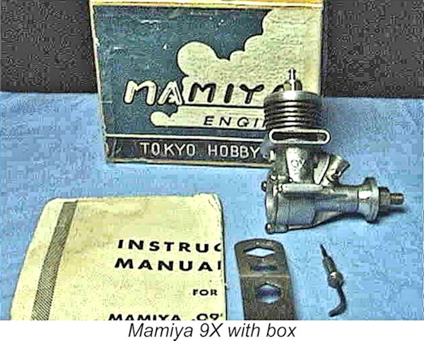
Regardless, these changes appear to have been effective - the revised model weighed only 74 gm (2.6 ounces) as opposed to the 82 gm (2.9 ounces) of the earlier variant. Still a bit on the heavy side for a plain bearing 1.61 cc glow-plug motor, but an unquestionable move in the right direction. Taken together, the increases in the compression ratio and transfer duration might logically be expected to improve performance considerably. Engine boxes for the Mamiya models are in very short supply outside of Japan, but I do at least have an image of a Mamiya 9X with its box. The Tokyo Hobbycrafts name appears on the label of that box, although that name had not been seen on an actual engine after its initial appearance on the original 60 FRV models. As far as I’m presently aware, no RV version of this model was ever produced. The Two Mamiya 9X Variants on Comparative Test I will freely admit that it was just plain curiosity that drove me to run a comparative test of the early and later variants of the Mamiya 9X. Given the seeming scarcity of these engines, there can't be that many such pairings in existence in the hands of a single tester, so if I didn't put them through their paces head to head and share the results, who would?!? Besides, I was really interested in learning how effective the designer's attempts to improve the engine's performance had proved to be.
Both engines proved to be extremely easy to start, requiring only a small port prime on a full fuel line as a preliminary. Response to the needle was also very good - the very fine thread doubtless helped to achieve very precise settings. Suction appeared to be excellent. Right from the start, it was clear that the early variant was woefully under-compressed. It slowed down markedly when the plug driver was removed after starting, also performing at what I would consider to be a very low level for a 1.6 cc glow-plug motor running on 15% nitro. As the speed got into the 9,000 RPM range, a misfire crept in that couldn't be eliminated using the needle. I was using a "hot" Fox glow-plug, so no hotter plug was available. The engine simply didn't want to run above 11,000 RPM. By contrast, the later variant with its substantially higher compression ratio and extended transfer period was a revelation! It didn't sag at all when the plug driver was disconnected and ran absolutely smoothly at all speeds tested. It was quite happy to run well past 13,000 RPM with no trace of a misfire. The following data tell the story:
The earlier low-compression version of the Mamiya 9X was clearly a non-starter in the .099 cuin. glow-plug motor sweepstakes. Its peak output of around 0.062 BHP @ 9,500 RPM put it fair and square into the also-ran category. By contrast, the improved later version with its various performance tweaks was well in the hunt by 1956 standards, peaking at around 0.118 BHP @ 12,600 RPM. Starting and running qualities of this variant left little to be desired.
A further interesting observation resulted from a comparison between the performance characteristics of the second Mamiya 9X variant and its larger companion, the 2.43 cc Mamiya 15. My own testing of that model (reported elsewhere) found a peak output of 0.221 BHP @ 12,700 RPM. The two designs are essentially identical, one simply being a re-dimensioned version of the other. It's noteworthy that the two identically-designed models peaked at more or less exactly the same speeds. The smaller 9X has a slightly lower specific output (BHP/cc), but this is not unexpected - specific outputs tend to become reduced for the same basic design as displacements go down. I suspect that removing the head of the early variant and skimming its sealing face, thereby raising the compression ratio, would do wonders for the performance of that unit. However, I have no plans to use the engine in anger, so it's best left as-is to preserve its originality while serving as a reminder of the extent to which the designer got it wrong first time around! The Mamiya 9X Diesel Model
These models are more or less in the “unobtanium” class - even my Japanese informants advised that they had very seldom encountered examples, although they had access to photographs and references in the contemporary Japanese modelling media. It appears that the numbers manufactured were very small and that very few if any of those that were produced ever made it out of Japan. Although I don’t have examples of either of these models on hand, I’m fortunate in being able to share an image of the Mamiya 9X diesel model. It may safely be assumed that the larger 15 diesel model looked essentially identical. Conclusion It appears that the Mamiya .09X and Mamiya 15 may well have been the last models to remain on offer from Tokyo Hobbycrafts. In a retrospective look at the Mamiya 60 which formed the subject of Peter Chinn’s “Foreign News” feature in the May 1979 issue of “Model Airplane News”, Chinn stated that the only Mamiya models listed for 1957 were those two models. Thereafter, nothing more was heard of the Mamiya model engine range, implying that 1957 was the final year of production, both for the Mamiya 9X and the Mamiya range as a whole. Well, there you have it – all that I’ve been able to learn about the .099 cuin. model engines which were marketed under the Mamiya trade-name. I hope that some of you found something of interest here! _________________________ Article © Adrian C. Duncan, Coquitlam, British Columbia, Canada First published December 2025 |
||||
 This is the first of what I hope will be a series of articles looking in detail at the various displacement categories which were included in the Mamiya model engine range from early post-WW2 Tokyo, Japan. I’ve covered the history of the range in general in a
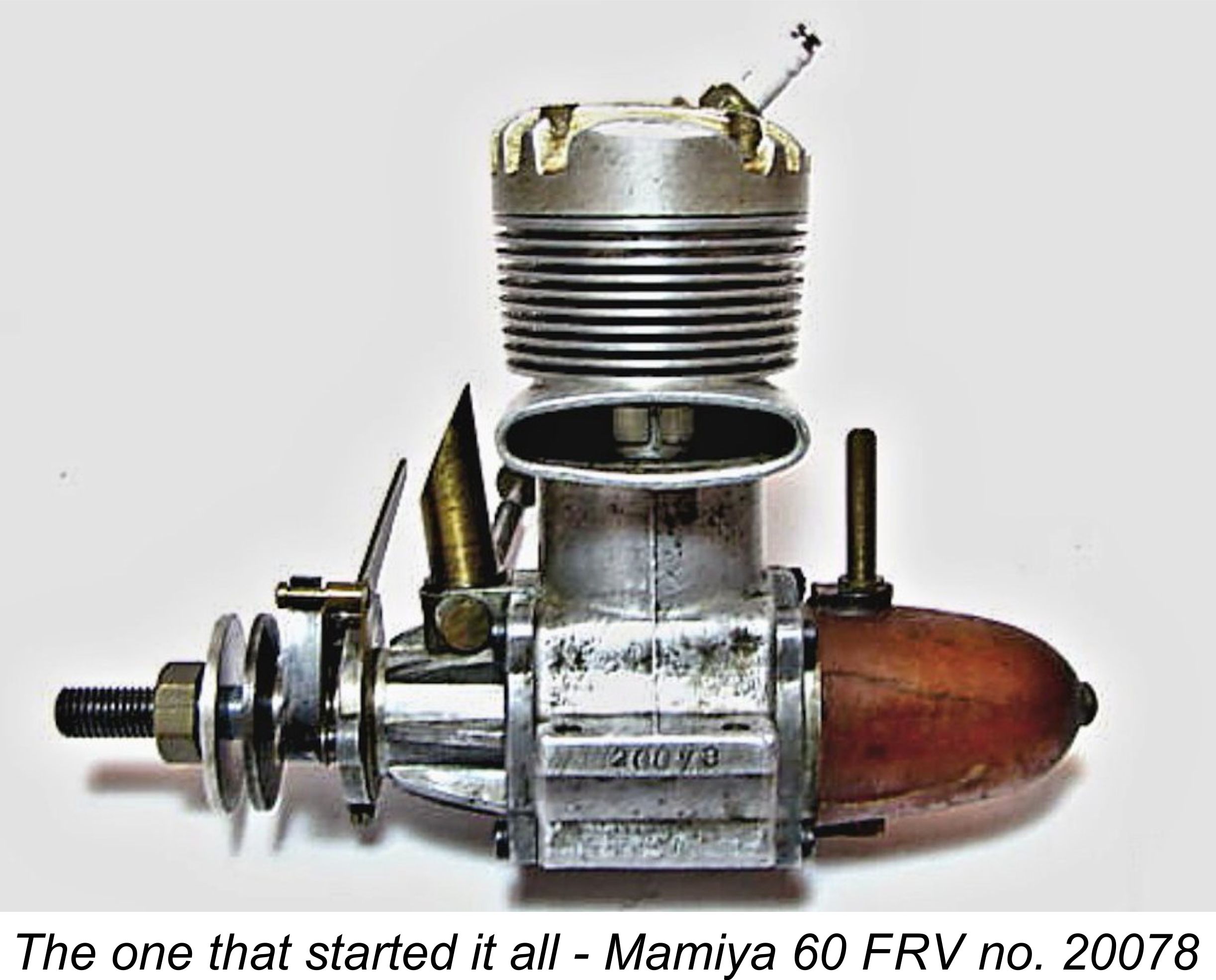
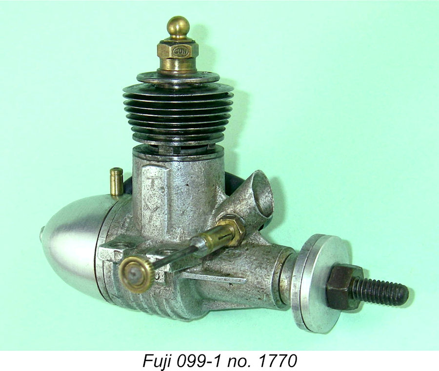 The manufacturers of the Mamiya engines, Tokyo Hobbycrafts, appear to have been among the first post-war producers to enter the .099 market, which they evidently did in 1948 with their now very rare “Chochin” .099 model, of which more below. Fuji followed suit in 1949 with their first sand-cast .099 model seen at the left, while
 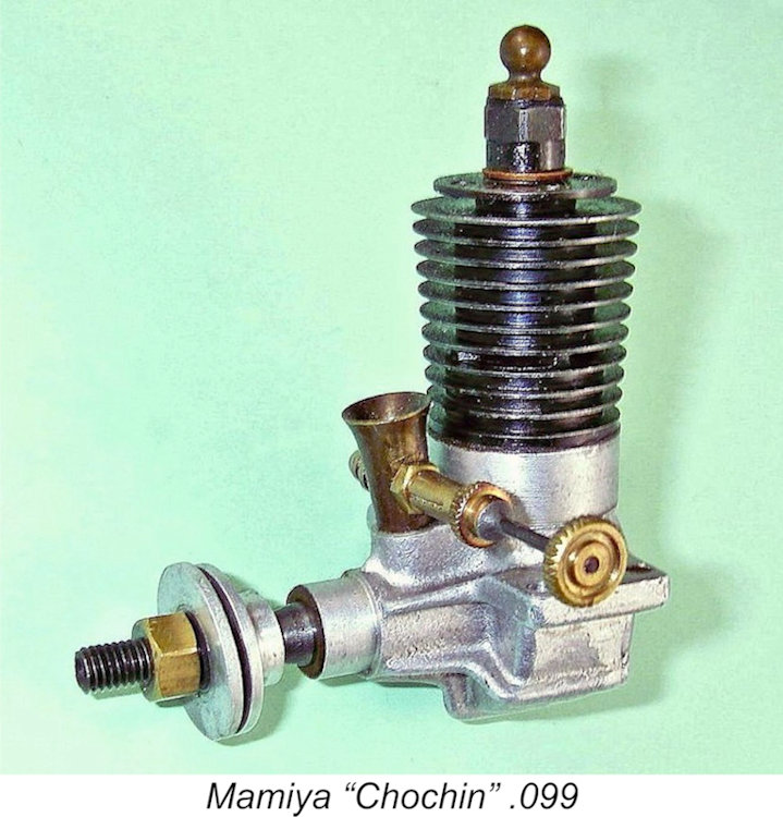 Although it’s not possible to be absolutely certain, present indications are that the Mamiya range entered its major expansion phase in late 1948 with the introduction of the previously-mentioned radially-ported “Chochin” models in .099 and .275 cuin. displacements. The term "Chochin" is not a factory designation – rather, it’s a Japanese modeller's nickname based on the visual similarity of the cylinder to the traditional Japanese chochin paper-and-bamboo lantern. The company name for the engine was simply the Mamiya 09.
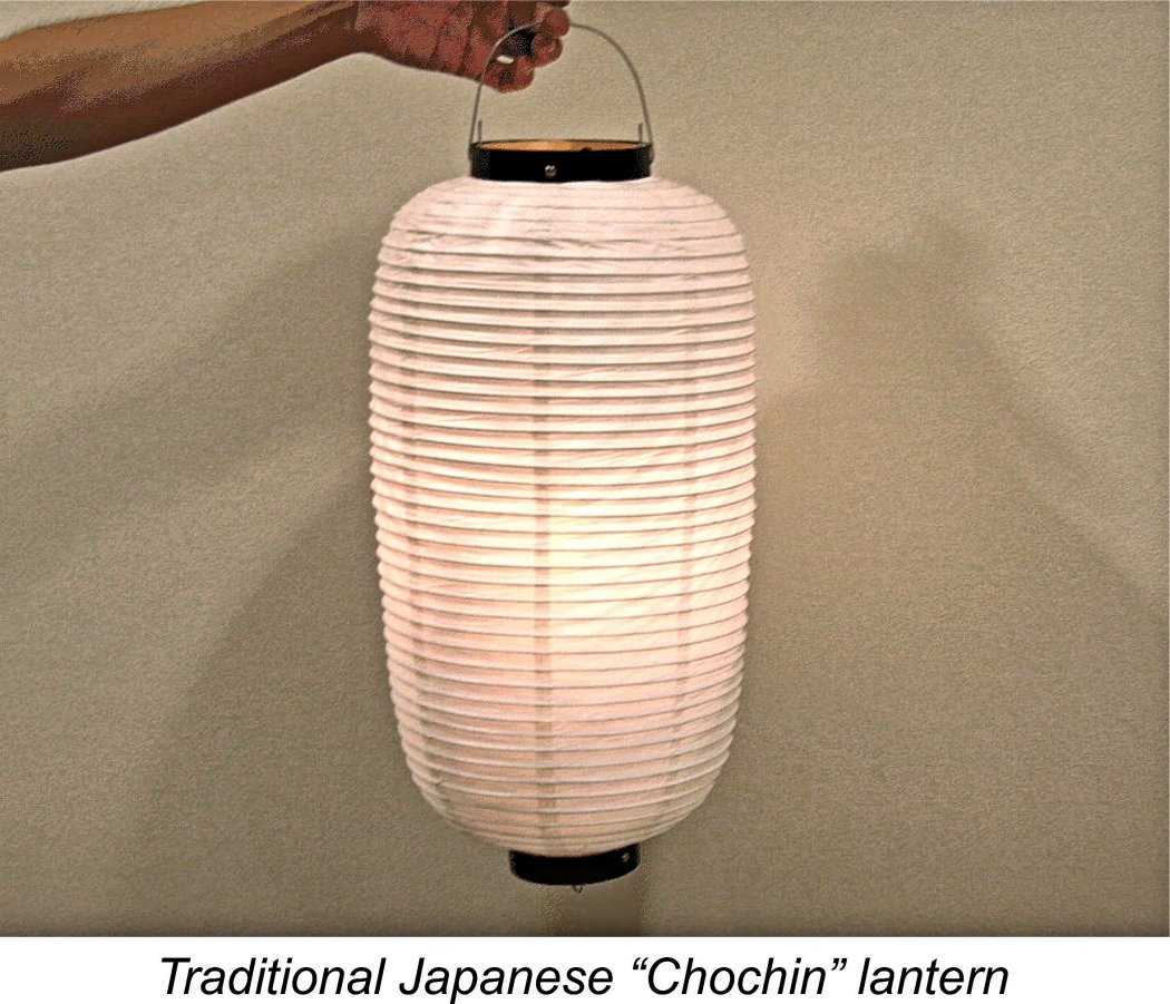 the fact that the measured compression ratio of my own illustrated example of the "Chochin" .099 model is a very modest 6 to 1 - a figure far more typical of spark ignition practise than of glow-plug design. That said, all examples of these quite rare engines of which I’m currently aware are glow-plug versions. If spark ignition models exist, they're extremely elusive.
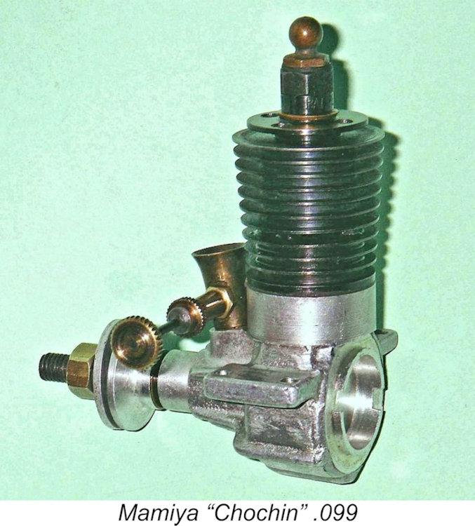
 I’m presently uncertain of the precise date at which the “Chochin” model was replaced by the far more up-to-date loop-scavenged .098 cuin. FRV design by which the Mamiya range is best remembered today. However, it seems to have been at some point in 1949. This series is perhaps the best-known and certainly the most prolific model engine series sold under the Mamiya name.
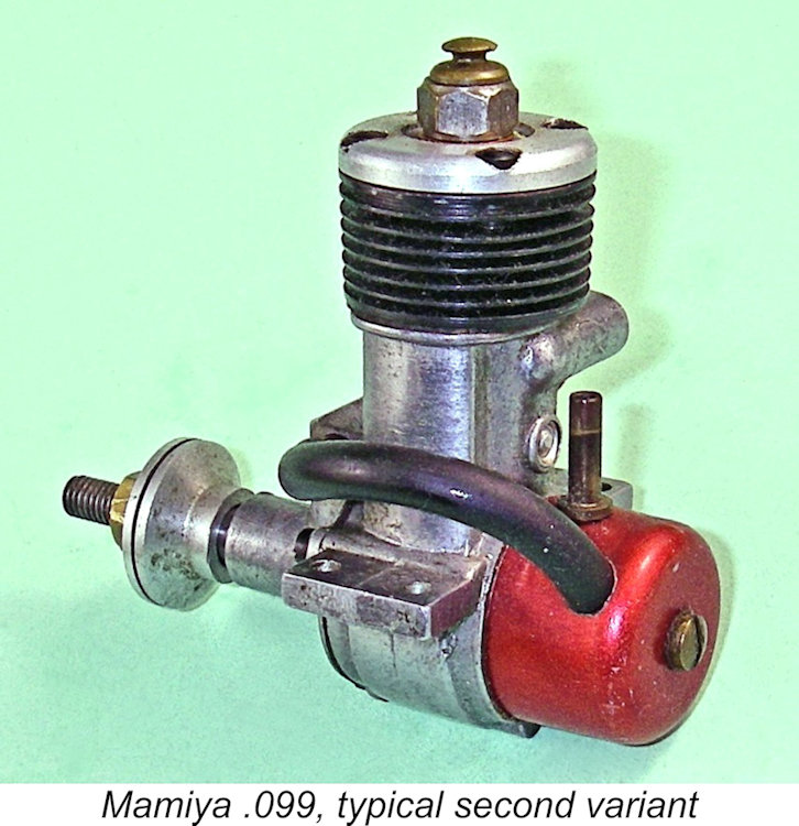
 What appears to be the original version of this neat little engine has neither a tank nor any provision for one. There is a central boss formed in the rear of the crankcase, showing that the notion of adding a tank at some point had already been considered and provision made in the casting. However, this boss is not drilled and tapped for a tank retaining bolt. Furthermore, the circular rim of the integral backplate is not machined to accommodate a tank. Accordingly, the option of mounting an after-market accessory tank without modification was not left open.
 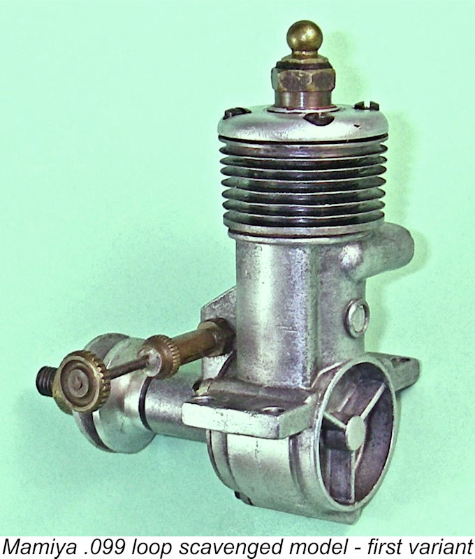 This variant bears no marks of identification whatsoever. It has a cylinder head which is rounded in profile at the edges and features a slightly raised central “boss” into which the plug screws. The “spigot” which locates the head in the upper cylinder is of considerable depth, and the addition of the raised boss in the centre means that this head requires the use of a long-reach glow-plug to match the thread depth and maintain the compression ratio. The head is attached by four screws which thread into tapped holes formed in the thickened upper flange of the cylinder. These screws play no role in securing the cylinder to the case.
 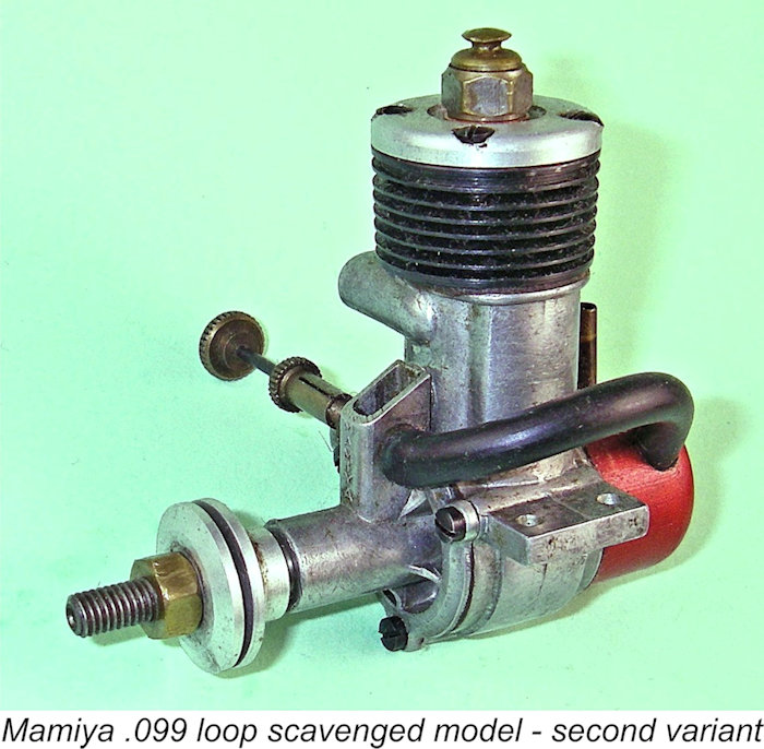 The next version of the Mamiya .099 shows a number of detail modifications and improvements by comparison with the version just described. It is very difficult to believe that the makers would have started with this version and then reverted to a less refined and less sturdy model, so the clear presumption is that the variant to be described next is a later model.
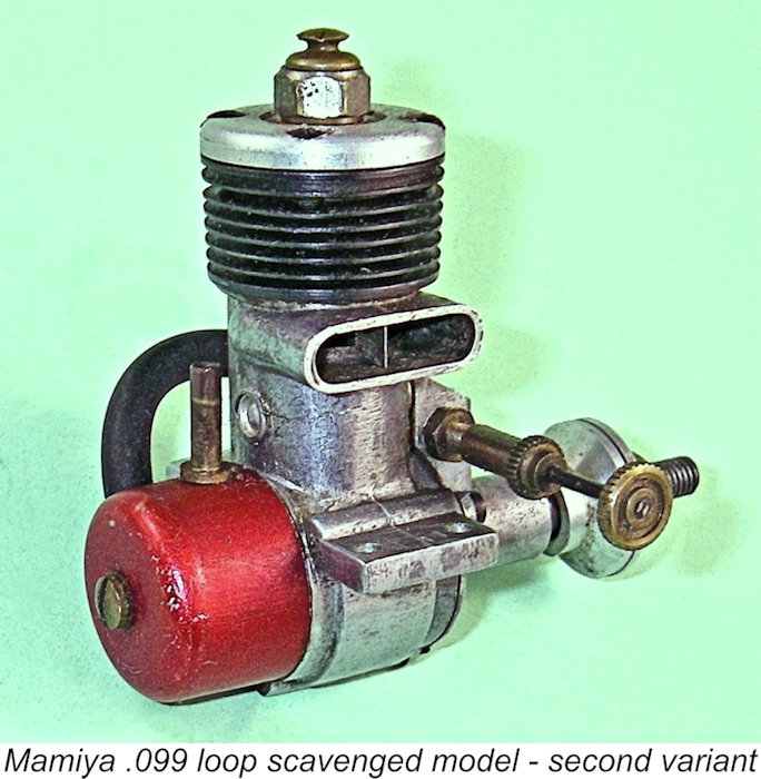
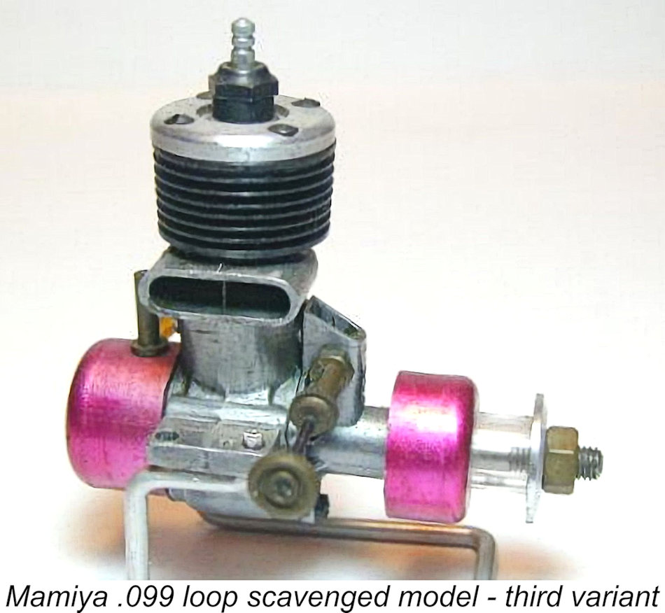 The next stage in the evolution of the Mamiya .099 model was a switch from the more-or-less conventional prop driver used on the first two variants to a large-diameter wrap-around unit. This far more prominent prop driver was color-anodized to match the tank, which was retained unaltered. The idea appears to have been to discourage the entry of dirt into the front of the main bearing. The rest of the engine more or less adhered to the description of the second model summarized above.
 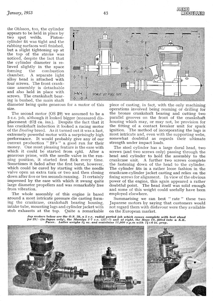 Lieutenant McNaughton was an aeromodelling enthusiast who had evidently spent some time in Japan or Hong Kong while on leave in the Far East and had acquired several Japanese motors, two of which he loaned to “Aeromodeller” as subjects for their article. The article focused on the contemporary O.S. 29 twin-stack model as well as the Mamiya .099, also mentioning the
 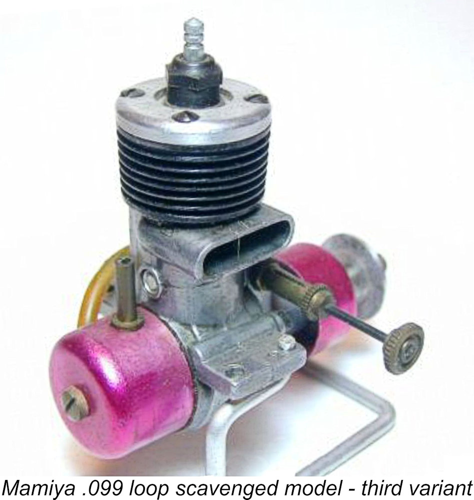 There was clearly no way that any contemporary British or even American manufacturer could have competed successfully or profitably in the Asian marketplace at the time based on these prices. Here we see a subtle and under-appreciated factor which goes far to explain the early success of the post-war Japanese manufacturers - they had essentially no overseas competition in the Asian market which they were best placed to serve, thus having that not-inconsiderable market to themselves.
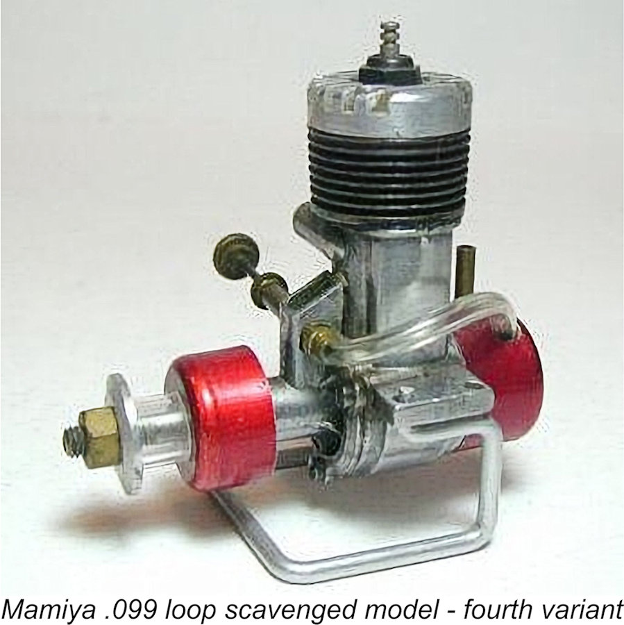
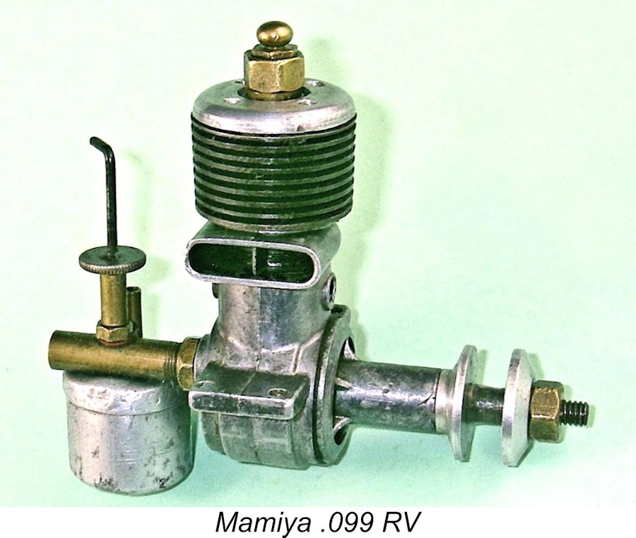 Perhaps the rarest of all the Mamiya .099 models is the little-known Mamiya .099 RV. This was a rear disc valve unit based on the design of the conventional FRV model just described, making it appear likely that it was a contemporary of that model dating from 1951-52. However, it was not merely a disc-valve version of the FRV model - there were many significant design departures.
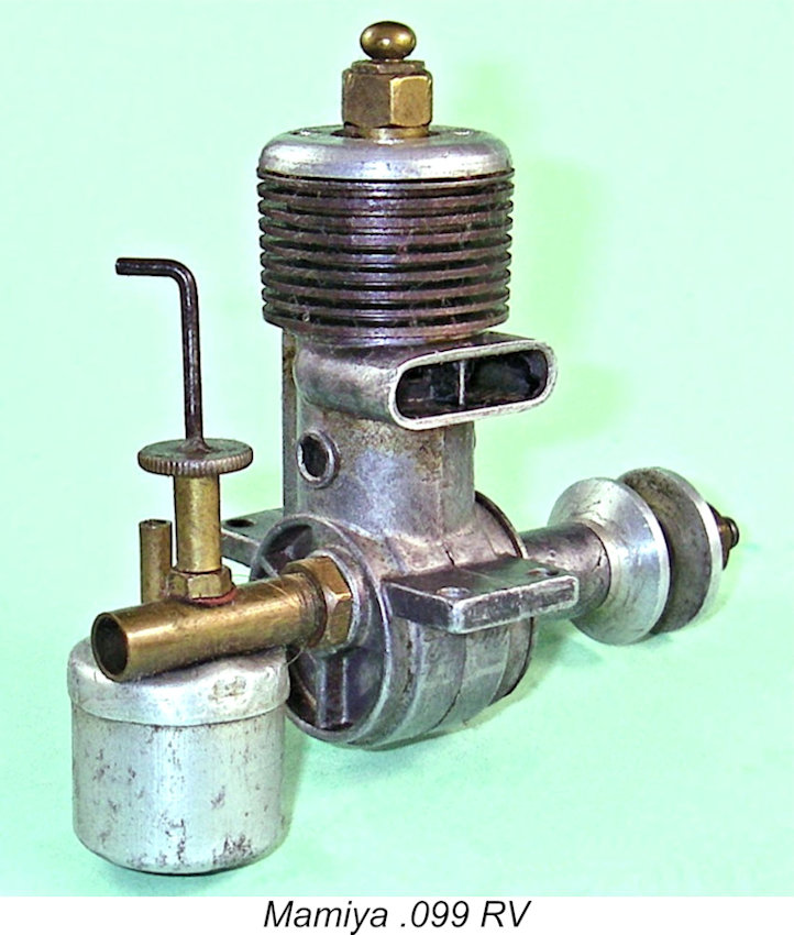
 Because of this screw-in head assembly, the orientation of the head when tightened could not be guaranteed. The combustion chamber was therefore formed as a simple bowl shape without a squish band or accommodation for the piston baffle. The steel piston differed from that of the FRV variant, being apparently stamped to its final form. It used a domed crown with a very minimal curved deflector on the transfer side. Since I chose not to dismantle my example of this very rare engine, I can't provide any further internal structural details.
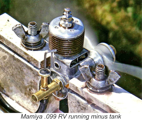
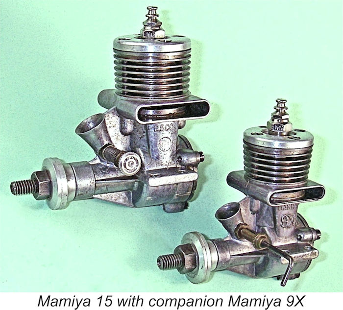 In late 1954 or thereabouts, the fourth model of the FRV Mamiya .099 described earlier was replaced by a completely re-designed .099 cuin. model known as the Mamiya 9X. This new .099 model seems to have been released concurrently with an all-new companion model, the Mamiya 15, of which much more elsewhere. The two engines shared an identical design layout, one being simply a re-scaled version of the other.
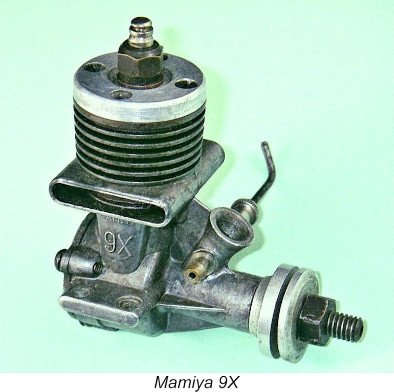
 The new cylinder was considerably more sturdy than that of its predecessor, hence being substantially bulkier and heavier. This component alone accounted for much of the engine's increased weight. The integrally-turned cooling fins were even thicker than they had been on the later .099 model described earlier. The un-finned cylinder head was reminiscent of its predecessor in having the more “squared-off” profile and the shallow recess for the plug. However, the new head was somewhat thicker overall than its predecessor, and this in turn meant that the engine was back to requiring a long-reach plug despite the retention of the recess.
 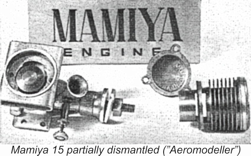 Fortuitously enough from my perspective, the “Motor Mart” article which appeared in the June 1955 issue of "Aeromodeller" featured a description of the identically-configured Mamiya 15, including an image of a partially-dismantled example of that model. The components of the Mamiya 9X were identical apart from being dimensioned at a lesser scale. Accordingly, since this image does much to clarify the following description, it is reproduced here.
 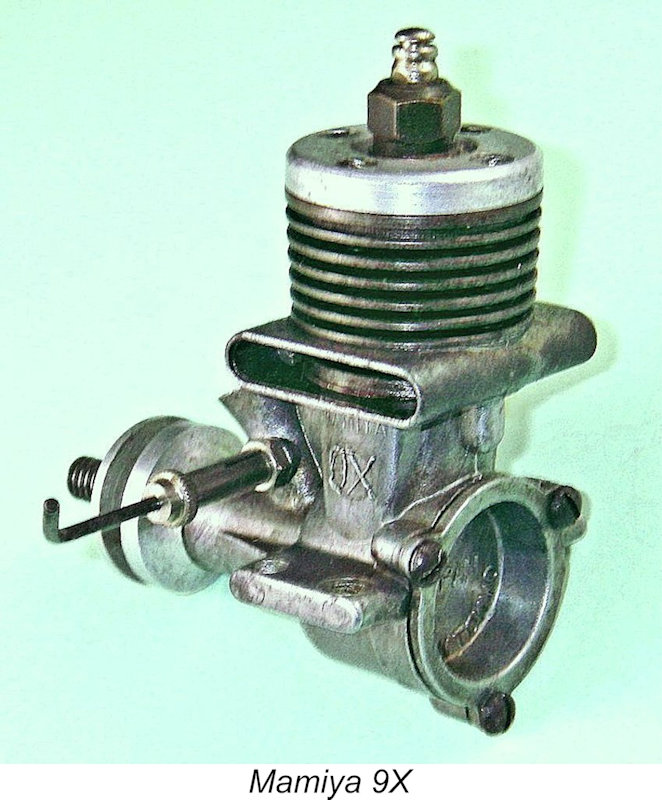 The result was a crescent-shaped cavity within the cylinder location flange on each side which was open to the corresponding bypass passage outside the lower cylinder wall and communicated directly with the cylinder bore along its entire inner edge where it intersected the bore. This approach allowed the use of a flange which was sufficiently thick to resist distortion while at the same time minimizing the unavoidable delay between the opening of the exhaust and transfer ports respectively. Ingenious ……………
 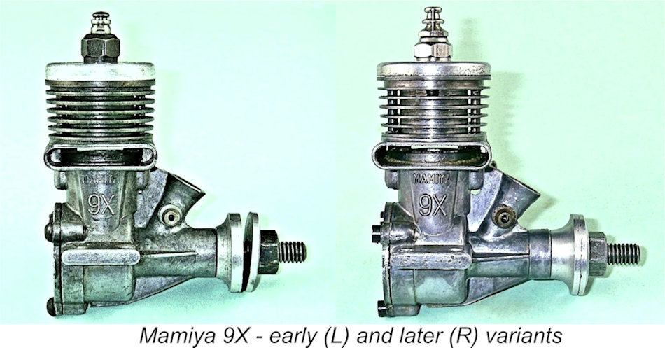 It’s clear from the evidence that the Mamiya designer soon came to the conclusion that the performance of the Mamiya 9X was in need of a boost. At some point along the way, probably quite early on, a number of design changes were implemented in the Mamiya 9X. Two of these were aimed directly at improving the engine’s performance, something which it evidently needed.
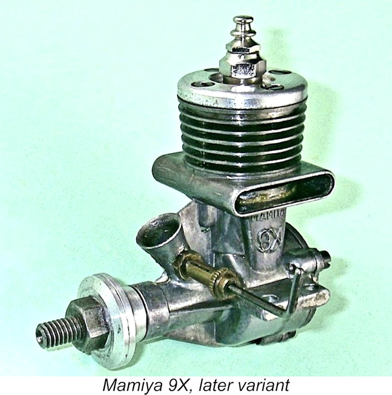
 Reference to the performance data summarized earlier for the previous Mamiya .099 side-stack model shows that while the original Mamiya 9X was a clear step backwards from that model, the later high-compression version represented a definite improvement. It developed some 20% more power and peaked at a significantly higher speed.
  Like its 15 companion, the 9X described above was also produced in diesel form, albeit in very small numbers. The diesel models of both the 9X and 15 were essentially identical to their glow counterparts apart from the addition of diesel heads. In the absence of an example to examine, the configuration of the diesel head remains unknown, as do the details of any internal changes that may have been made.
 | |